

Page 1
SM06
TAC/COM SERIES
Control Head
INSTALLATION AND OPERATION MANUAL
REV 4.10 January 4, 2006
Northern Airborne Technology Ltd.
1925 Kirschner Road
Kelowna, BC, Canada.
V1Y 4N7
Telephone (250) 763-2232
Facsimile (250) 762-3374
Copyright 2005 by Northern Airborne Technology
CONFIDENTIAL AND PROPRIETARY TO NORTHERN AIRBORNE TECHNOLOGY LTD.
Page 2

Page 3

SM06 Rev. 4.10 Tac/Com Control Head Manual
Periodically NAT will release manual amendments. In order to maintain the most
accurate and up to date manual these amendments should be carried out immediately
upon receipt and recorded on the following amendment record.
AMENDMENT RECORD
Amendment
Number
Amendment
Date
Section(s)
Changed
Date
Entered
Entered By
Insert any Amendment Instruction sheets after this page.
Jan 4, 2006 Page ii
ENG-FORM: 820-0110.DOT
CONFIDENTIAL AND PROPRIETARY TO NORTHERN AIRBORNE TECHNOLOGY LTD.
Page 4

Page 5

SM06 Rev. 4.10 Tac/Com Control Head Manual
Table of Contents
Section Title Page
1 Description
1.1 Introduction 1-1
1.2 General 1-1
1.2.1 Tac/Com Control Head Family 1-2
1.2.2 Accessories 1-3
1.3 Purpose of Equipment 1-5
1.3.1 Interface Considerations 1-6
1.3.2 Mixed Transceiver System 1-6
1.3.3 Radio Capability Increase With Tac/Com 1-7
1.3.4 Master/Slave Configuration 1-8
1.3.5 Frequency Data Considerations 1-9
1.4 Hardware Design Features & Considerations 1-10
1.4.1 General 1-10
1.4.2 Display Filtering/Lighting Options 1-10
1.5 Specifications 1-11
1.5.1 Electrical Specifications 1-11
1.5.2 Physical Specifications 1-12
1.5.3 Environmental Specifications 1-13
1.6 Unit Nomenclature 1-13
1.6.1 Series Designation 1-13
1.6.2 Number Of Radios 1-13
1.6.3 Display Type 1-14
1.6.4 Display Filter/Lighting Suffix Information 1-14
1.6.5 Interface-Specific Suffix Information 1-15
2 Installation
2.1 Introduction 2-1
2.2 Unpacking and Inspection 2-1
2.2.1 Warranty 2-1
2.3 Installation Procedures 2-1
2.3.1 Warnings 2-1
2.3.2 Cautions 2-2
2.3.3 Cabling and Wiring 2-2
2.3.4 Mechanical Mounting 2-3
2.3.5 Notes 2-3
2.4 Post Installation Checks 2-4
2.4.1 Voltage/Resistance Checks 2-4
2.4.2 Power On Checks 2-4
Jan 4, 2006 Page iii
ENG-FORM: 820-0110.DOT
CONFIDENTIAL AND PROPRIETARY TO NORTHERN AIRBORNE TECHNOLOGY LTD.
Page 6

Page 7

SM06 Rev. 4.10 Tac/Com Control Head Manual
Section Title Page
2.5 Troubleshooting 2-6
2.5.1 Weak Receive/Transmit, Intermittent Operation, Erratic Squelch 2-6
2.5.2 Strange Noises, No Receive Audio, Transmit Keying problems 2-6
2.5.3 Some Frequencies Can't be Edited 2-6
2.5.4 Display Brightness is Too Low, Can't Increase to Full Brightness 2-6
2.5.5 Amber (RX) Squelch light comes on, but no RX audio is heard. 2-7
2.6 Final Inspection 2-7
2.7 Continued Airworthiness 2-7
2.8 Installation Drawings 2-8
2.8.1 Outline drawings 2-8
2.8.2 System Connector (J-100) 2-8
3 Operation
3.1 Introduction 3-1
3.2 General 3-1
3.3 Initial Operation 3-2
3.3.1 Power-up Help 3-2
3.3.2 Initial Operating Display 3--2
3.4 Front Panel Controls 3-3
3.4.1 Radio Specific Controls 3-4
3.4.2 General Controls - NORMAL Operation 3-6
3.5 Editing 3-10
3.5.1 Channel Editing 3-11
3.5.2 Summary of Channel Editing 3-14
3.5.3 Summary of Channel Labels 3-15
3.5.4 Summary of Subaudible Tones 3-16
3.6 Status Line Editing 3-19
3.6.1 NEXT and SELECT Switch Use 3-20
3.6.2 Status Edit Features 3-21
3.7 Channel Display Summary 3-23
3.7.1 Display Switch Set to 'ID' 3-23
3.7.2 Display Switch Set to 'RX' 3-24
3.7.3 Display Switch Set to 'TX' 3-24
3.8 Changing Display Brightness 3-25
3.9 Scanning 3-25
3.9.1 Scan Modes 3-27
3.10 NAT NTX138 Wide-band/Narrow-band Operation 3-28
3.11 Master Edit Mode 3-29
3.11.1 Entering Master Edit Mode 3-29
3.11.2 How Data is Stored in the Control Head 3-30
3.11.3 Editing Considerations 3-30
3.12 Installation & Configuration Mode 3-31
3.12.1 Entering Configuration Mode 3-31
3.12.2 Configuration Option Table 3-32
Jan 4, 2006 Page iv
ENG-FORM: 820-0110.DOT
CONFIDENTIAL AND PROPRIETARY TO NORTHERN AIRBORNE TECHNOLOGY LTD.
Page 8

Page 9
SM06 Rev. 4.10 Tac/Com Control Head Manual
Section 1 Description
1.1 Introduction
This manual contains information on the NAT Tac/Com control heads. All derivative
products and interface cards will be covered by manual supplements, which can be
obtained from NAT as required.
Information in this section consists of purpose of equipment, features and specifications.
1.2 General
The Tac/Com control head provides exceptional flexibility and ease of operation while
using minimal panel space. In a Dzus panel height of only 4⅞ inches, up to four
transceiver systems can be controlled and accessed using a Tac/Com control head.
The controlled radio systems may be either NAT transceivers or combinations of
different manufacturer's transceivers.
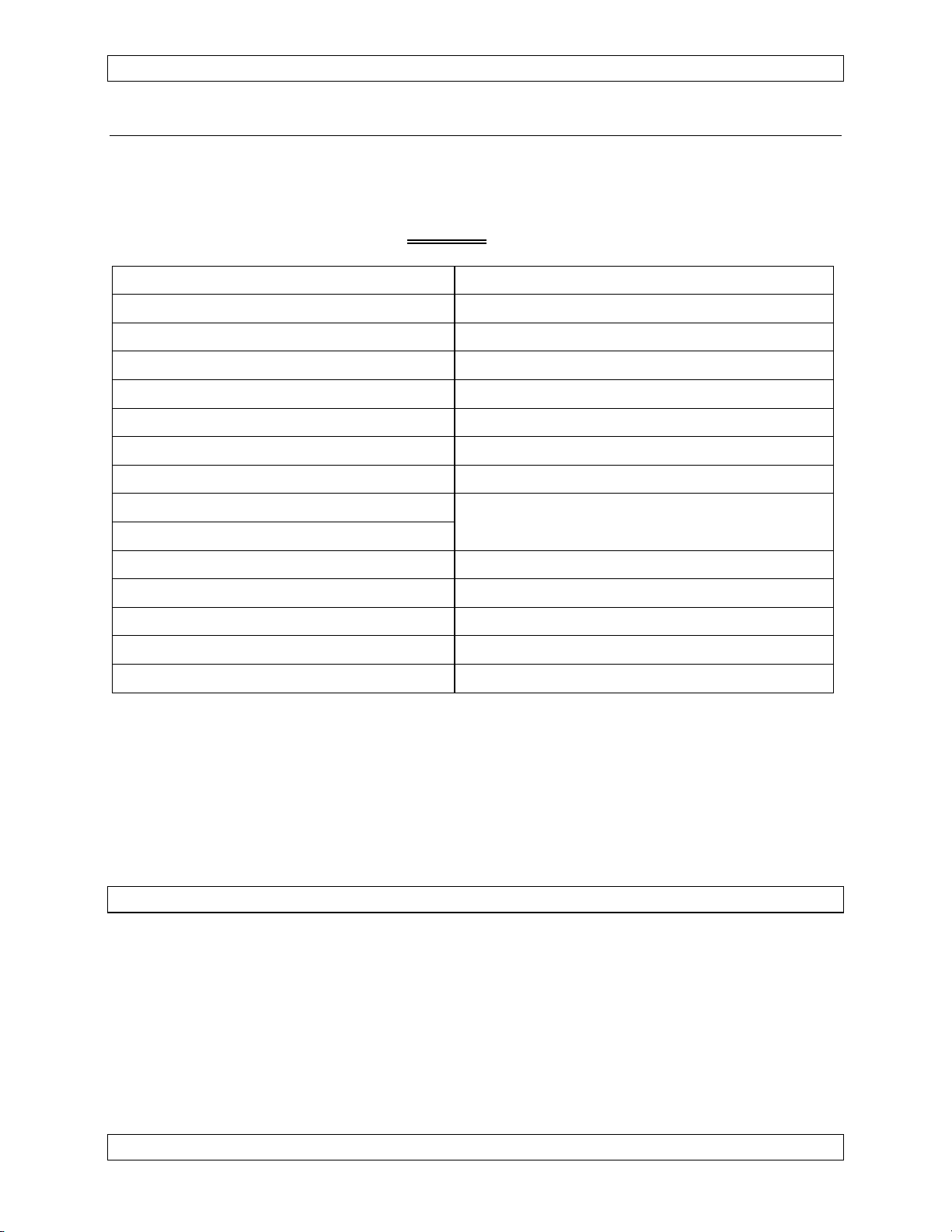
Tac/Com controls are available in two basic families: Tac/Com I (both LED and LCD
displays), and Tac/Com II (LED only). Note that the Tac/Com I or ‘CH ‘ series control
heads have been discontinued since 1995. Tac/Com II control head variations include
2-, 3- or 4-transceiver support, master or slave versions and custom panel lighting, and
support expanded channel storage (up to 128 channels per radio), remote channel
selection, display auto-dimming, and full software configuration of the control head.
Features Tac/Com I Tac/Com II
Control/Display
Types
2 & 4 Radio LCD,
2 & 4 Radio LED
2, 3 & 4 Radio LED.
Channels/Radio 32 (NT) or 56 (non-scanning) 128 maximum.
Special
Features
HELP, Alphanumeric
Labelling of Channels
HELP, Alphanumeric
Labelling of Channels, Highspeed Scrolling, Remote
Radio/Channel Selection,
Auto Night Dimming.
Master/Slave Yes Yes
DTE12 Support No Yes
USFS Guard &
No Yes
Tone Capability
NT136-PAS
No Yes
Compatible
Jan 4, 2006 Page 1-1
ENG-FORM: 800-0108.DOT
CONFIDENTIAL AND PROPRIETARY TO NORTHERN AIRBORNE TECHNOLOGY LTD.
Page 10
Tac/Com Control Head Manual SM06 Rev. 4.10
The Tac/Com control head carries its own operator's manual in internal software, and
can provide on-line help to the operator for all functions. An initial help mode at powerup can provide a complete tutorial of the control head and its operating and storage
functions, and pressing the HELP button during either EDIT operation brings up
context-sensitive help for the specific storage or data entry function being carried out.
This provides a simple way for new staff to train, as well as providing a private method
to refresh their knowledge of the system whenever they chose. The help information
‘manual’ can never be lost or misplaced because it forms part of the basic control head
itself.
Radio control functions and transceiver interfaces are determined by a combination of
Tac/Com control head software and internal radio-specific interface cards. To specify a
complete control head, you must select the basic size format and the internal interfaces.
The range of control heads is shown graphically in the Tac/Com control head family
drawing below.
1.2.1 Tac/Com Control Head Family
Each control head type can have user-specified interfaces installed as required. Control
heads with LCD displays are no longer available (available as Tac/Com I only). Current
models are available with LED displays (Tac/Com II).
Two-Radio Control Heads
Three-Radio Control Heads
Page 1-2 Jan 4, 2006
ENG-FORM: 800-0108.DOT
CONFIDENTIAL AND PROPRIETARY TO NORTHERN AIRBORNE TECHNOLOGY LTD.
Page 11
SM06 Rev. 4.10 Tac/Com Control Head Manual
Four-Radio Control Heads
1.2.2 Accessories
The Tac/Com family encompasses numerous specialized accessories to extend system
capability, as well as transceivers and the control heads reviewed in this manual.
NAT transceiver capabilities are covered in separate manuals. For reference, the
additional system components include:
1.2.2.1 Remote Mount VHF FM Transceivers
*NT030A-xxx Low Band
*NT030B-xxx Low Band
*NT136-xxx High Band
*NT150-xxx High Band
NTX066-xxx Mid Band
NTX138-xxx High Band/Narrow Band Compatible, available with USFS
Custom Guard option
NTX138E-100 High Band/Direction Finding (DF) Capability/Enhanced
environmental specifications
1.2.2.2 Remote Mount UHF FM Transceivers
*NT403-xxx Low Band
*NT450-xxx High Band
*NT450x-xxx High Band
*NT806-000 800 MHz
NTX403-xxx Low/High Band
* No longer available as new products.
Jan 4, 2006 Page 1-3
ENG-FORM: 800-0108.DOT
CONFIDENTIAL AND PROPRIETARY TO NORTHERN AIRBORNE TECHNOLOGY LTD.
Page 12

Tac/Com Control Head Manual SM06 Rev. 4.10
1.2.2.3 TE12/DTE12/DP12 DTMF Tone Generator/Keyboard Data Entry Unit
These devices can output DTMF signalling tones from either keyboard control or stored
sequences, and can serve as a direct keyboard data entry system for Tac/Com control
heads to change channels and frequencies. Consult NAT Ltd. for further information.
1.2.2.4 RA10 Remote Attenuator
This group of remote signal attenuators can be used to alter receive and transmit
performance and range under operator control. They allow compliance with restricted
transmit power regulations even when the radio itself cannot alter its transmit level.
They are used extensively in Europe for changing TX power to even lower levels than
the 1W output possible via Tac/Com transceivers directly, and to reduce RX
interference from closely spaced repeaters by reducing RX sensitivity.
1.2.2.5 Tactical Direction Finding (TDF) System
This 2-axis DF system allows both left-right and fore-aft sensing with a pictorial display.
This provides exceptional accuracy during search and rescue and remote tracking
operations, and also provides a positive indication of station passage (impossible with
single axis systems) to aid in exact target location.
1.2.2.6 CC250/450 Communications Controllers
The CC250/450 is a compact, easy to install communications controller. It is designed
to provide relay and/or simulcast operation for up to 4 transceivers. With these
functions, the aircraft can become an airborne repeater or a multi-frequency transmitting
platform. When used to its potential, the CC250/450 provides increased efficiency and
reduced workload for communication operations. Only the CC450-0V2 is currently in
production.
1.2.2.7 CTE12 Calquest Headset Adapter
The CTE12-100 Calquest Headset Adapter is designed to interface standard avionics
headsets to the Calquest Cabin Network Unit (CNU). The headset adapter provides a
DTMF keypad, status indicators, ring chime control, ring/in-use annunciator control and
VOX squelch capability. The headset adapter can interface directly to a headset or a
standard avionics audio panel.
1.2.2.8 UT12 Universal Tone Encoder/Decoder
The UT12-000 is capable of encoding and decoding 5-tone CCIR tone sequences and
DTMF tones. It is compatible with the NAT Tac/Com system, and when used in
conjunction with a TH-series Tac/Com control head provides broader and easier control
over tones. The control head or transceiver can select, enable, disable and display
tones by communicating with the UT12-000 through a serial port.
Page 1-4 Jan 4, 2006
ENG-FORM: 800-0108.DOT
CONFIDENTIAL AND PROPRIETARY TO NORTHERN AIRBORNE TECHNOLOGY LTD.
Page 13
SM06 Rev. 4.10 Tac/Com Control Head Manual
1.3 Purpose of Equipment
The Tac/Com series of control heads provides a centralized location for tactical radio
control and channelling of up to four independent transceiver systems. Only the
Tac/Com II series will be considered; for further information, contact NAT Ltd.
Alphanumeric labeling of each radio channel is provided, as well as a display of receive
and transmit frequencies, to ease pilot identification of the selected channel on each
radio.
At the Tac/Com (master) control head, individual radio receive volume and radio power
on/off status can be controlled. Individual radio functions can also be set, such as
scanning, tones, simplex/duplex, TX power and others. Annunciation is provided for TX
and RX activity on a per transceiver basis, and the main display can be set to show the
channel name (alphabetic label), the receive frequency and tone data, or the transmit
frequency and tone data for all radios via the general control group.
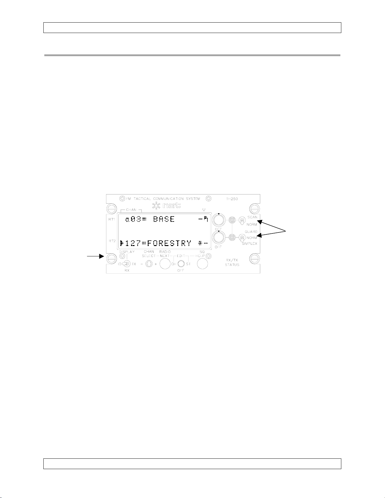
Radio
Controls
General
Controls
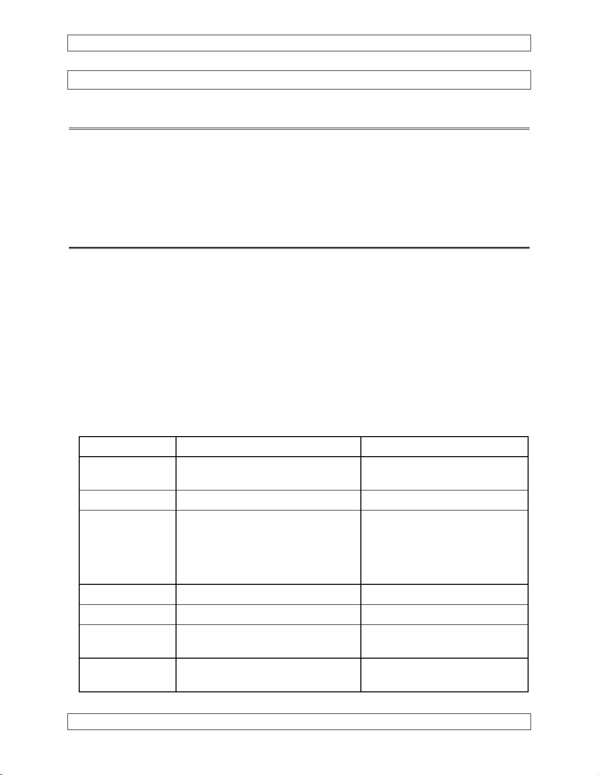
TH250 Control
(2 Radios, 256 Total Channels)
Within the control head, individual radio interface cards translate the control head
commands into suitable channelling data for each specific type of radio connected.
Software controlling these functions, as well as the built-in help screens for control head
operation, is located on the main control head CPU board and can be easily replaced to
upgrade or improve control head functions.
The software of the control head's computer can emulate many types of parallel tuned
radio controls and this allows the Tac/Com system to directly replace many existing
controls such as the C-960, C-961, C-962A, C-722A and C-1000. In addition, since the
Tac/Com control allows control of up to four simultaneous radio systems, the single
Tac/Com control can replace up to four individual controls, with a substantial reduction
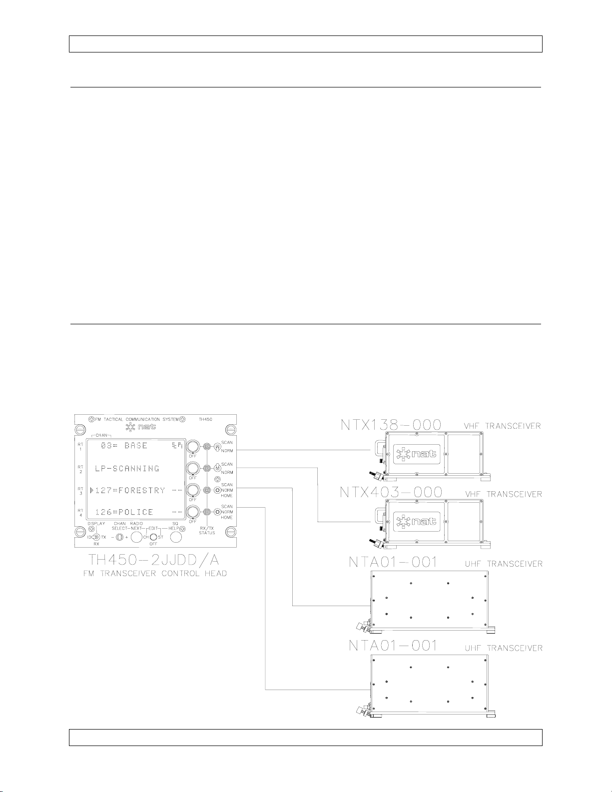
in cost and panel space. The following diagram illustrates a system that shows this
multiple radio capability using NAT NT-series agile transceivers. Any combination of
radios could be used by installation of the appropriate interface cards within the control
head. In the example below, an accessory DTE12 is used for DTMF tone generation
and direct keyboard data input to the TH450.
Jan 4, 2006 Page 1-5
ENG-FORM: 800-0108.DOT
CONFIDENTIAL AND PROPRIETARY TO NORTHERN AIRBORNE TECHNOLOGY LTD.
Page 14
Tac/Com Control Head Manual SM06 Rev. 4.10
1.3.1 Interface Considerations
Tac/Com offers direct plug compatibility for replacement of C-962/A and C-722/A control
heads (for use with the RT-9600 and RT-7200), including the second audio connector.
For USFS applications, Tac/Com provides some additional capability when used with the
RT-9600. Full guard receiver control can be brought out on the front panel, and the
limited tone capability of the RT-9600 (8 variable tones) can be replaced with the internal
tone capability of the Tac/Com ‘U’ interface, which provides all 32 standard CTCSS tones.
This interface remains plug-compatible, and also eliminates the awkward external tone
encoder required on USFS contracts. A USFS-compatible ‘V’ interface is provided for
use with NT150-050 guard-equipped radios, and the 'H' interface is designed for use with
the NTX138-050.
For use with existing Flexcomm installations, NAT provides an adapter cable (p/n
FC41-000 Flexcable) that permits direct connection from C-1000 airframe connectors
to the ‘F’ interface.
1.3.2 Mixed Transceiver System
The example shows a four radio Tac/Com control head running a mixed transceiver
group, to illustrate what is possible with the interface flexibility of Tac/Com internal
architecture. Transceivers may be a combination of fixed and agile radios, with and
without scanning, and can be from any of the supported interfaces that NAT provides.
See section 1.6.5 or consult Product Support at NAT for further information.
Page 1-6 Jan 4, 2006
ENG-FORM: 800-0108.DOT
CONFIDENTIAL AND PROPRIETARY TO NORTHERN AIRBORNE TECHNOLOGY LTD.
Page 15

SM06 Rev. 4.10 Tac/Com Control Head Manual
1.3.3 Radio Capability Increase With Tac/Com
Wherever possible, NAT has increased the capability of other transceivers via the
Tac/Com control head, and those features are summarized below, compared to the
original controls:
Feature Tac/Com I Tac/Com II C1000 C962/722
Stored Channels
PL Tones*
No. of Transceivers
32/56 per Radio 128 per Radio 30 Total 15 Total
38 + 83 DPL
38 + 83 DPL
32 for W.E.D.
32
32 for W.E.D.
8
1 - 4 1 - 4 1 1
(simultaneous)
Alpha Labels
Remote Selection
Yes Yes No No
No Yes No No
(channels & radio)
Master/Slave
Yes Yes No No
(both active)
*NAT NT-series Radios have the capability shown. Tac/Com controls can provide 32
PL tones for Flexcomm. Tac/Com II can also provide an internal tone upgrade for the
RT-9600/7200 to provide all 32 standard EIA CTCSS tones (‘U’ interface).
PL = Private Line (also known as CTCSS)
DPL = Digital Private Line
W.E.D. = Wulfsberg Electronics Division
Note: Only NAT's own NT-series transceivers support all the features provided by
Tac/Com controls. Tac/Com controls cannot give a radio functions of which it is
inherently incapable. For example, older crystal-controlled Flitefone 40's do not
become agile radios when connected to a Tac/Com head, and Flexcomm radios
do not acquire high speed scanning or DPL capability.
Jan 4, 2006 Page 1-7
ENG-FORM: 800-0108.DOT
CONFIDENTIAL AND PROPRIETARY TO NORTHERN AIRBORNE TECHNOLOGY LTD.
Page 16
Tac/Com Control Head Manual SM06 Rev. 4.10
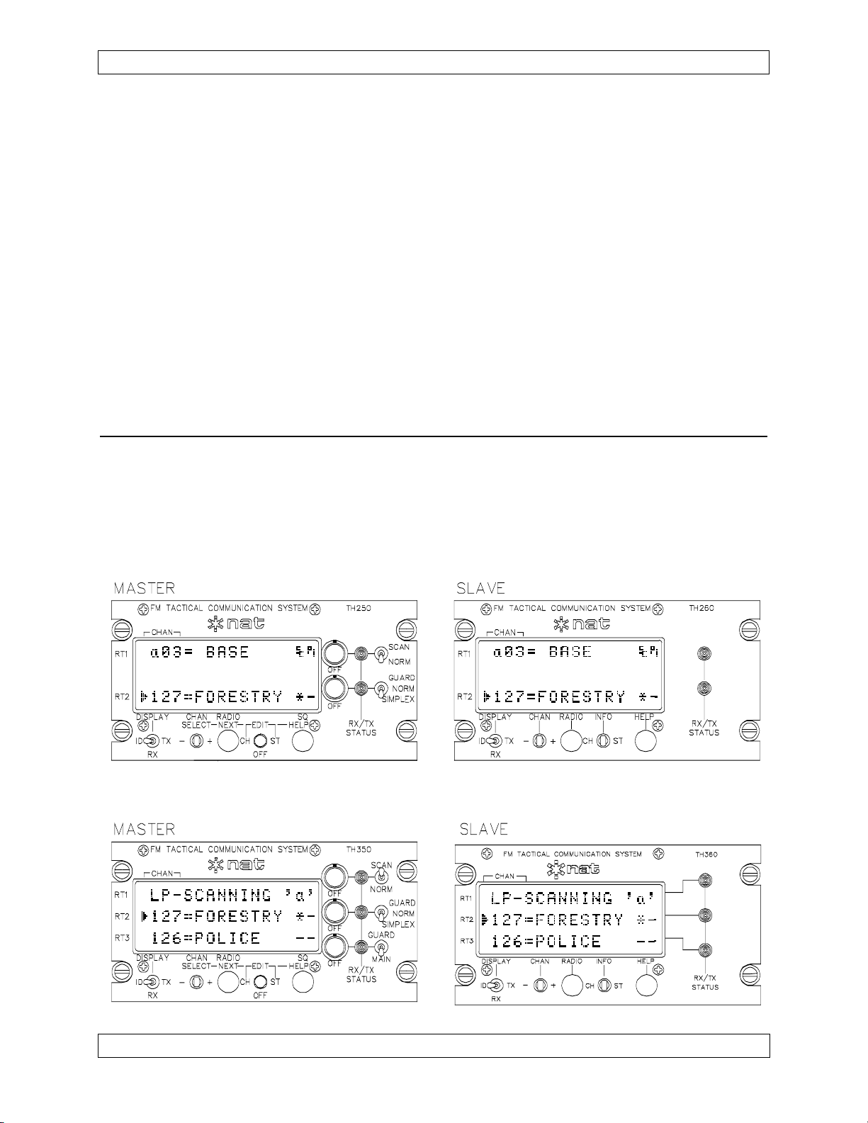
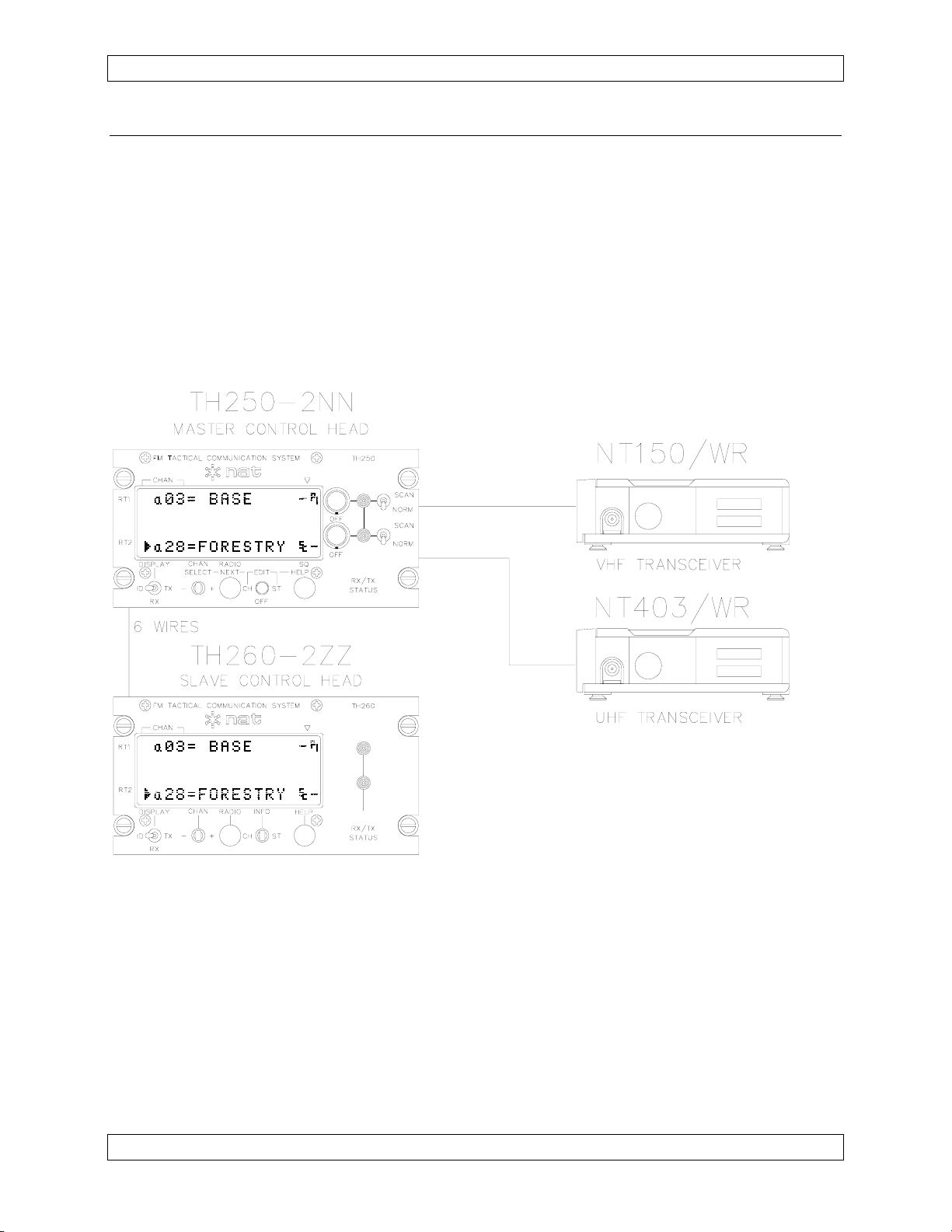
1.3.4 Master/Slave Configuration
One powerful configuration that NAT's Tac/Com controls support is the master/slave
configuration. In this configuration, two controls can be active at the same time (flight
crew and medical crew, for example), and both can select channels and radios. The
extraordinary aspect of this interface is the fact that this interconnect requires only 6
additional wires to give full support to both stations. Dual controls wired with other units
often require hundreds of wires, and still permit only a single control to be active at one
time.
A typical master/slave interconnect is illustrated below for clarification. Many
variations are possible, and the controls can be 2, 3 or 4 radio types, if required.
Page 1-8 Jan 4, 2006
ENG-FORM: 800-0108.DOT
CONFIDENTIAL AND PROPRIETARY TO NORTHERN AIRBORNE TECHNOLOGY LTD.
Page 17

SM06 Rev. 4.10 Tac/Com Control Head Manual
1.3.5 Frequency Data Considerations
Tac/Com controls have an intelligent editor that prevents incorrect data entry when
programming frequencies for a given agile radio. VHF radios can receive only valid
VHF frequencies; UHF radios only UHF frequencies at the correct intervals, and so on.
This greatly eases operator use, and prevents many common pilot errors. The C-1000
permits many types of incorrect entries for radios because of its thumbwheel entry
system. This intelligent editor is especially useful when the Tac/Com control head has
been set to emulate a C-1000 (i.e., channel any Flexcomm radio), as it detects the
range of the radio as the data is being entered, and then restricts subsequent
information to correspond to the exact radio type.
Radios in each band-split have specific channel interval assignments (by law), and are
typically on 25 kHz, 15 kHz, 12.5 kHz, 6.25 kHz, 5 kHz or 2.5 kHz intervals. Which
multiples are possible depends on the design of the radio's synthesizer circuitry, history
and restrictions of the country of operation. Tac/Com automatically picks the correct
multiples for each radio type based on the stored installation data, and ensures that only
valid choices are possible for the operator.
If the operator enters invalid data via either external data entry or other procedure, the
control will advise of this error. User intervention is then required to correct the data
before proper radio operation can be achieved.
1.3.5.1 Frequency Programming
There are three ways to program channel data into a Tac/Com control head:
a) From the front panel controls (edit mode).
b) From a DTE12 Keyboard/Data Unit (edit mode, Tac/Com II only).
c) From a PC via NAT's data loading software & the system serial port.
1.3.5.2 Channel Selection
There are three ways to select a channel on a Tac/Com control head:
a) From the front panel controls.
b) From the remote select switches (Tac/Com II only).
c) From a DTE12 Keyboard/Data Unit (Tac/Com II only).
Jan 4, 2006 Page 1-9
ENG-FORM: 800-0108.DOT
CONFIDENTIAL AND PROPRIETARY TO NORTHERN AIRBORNE TECHNOLOGY LTD.
Page 18

Tac/Com Control Head Manual SM06 Rev. 4.10
1.4 Hardware Design Features & Considerations
1.4.1 General
The Dzus mounted Tac/Com control heads use extremely high quality components,
including sealed gold contact switches, gold contact connectors and fully masked,
conformal-coated FR4 flame retardant circuit boards. Each unit is fully temperature
cycled, life-tested, and then supported with a solid one-year warranty and extensive
field support to ensure the best possible customer satisfaction.
A wide range energy conversion power supply is used in the control head, allowing
operation from 16-33 Vdc, for nominal 28 Vdc systems. Panel lighting must be adjusted
to suit the specific application, and is normally supplied as natural colouration 28 Vdc
incandescent lighting. Options include blue/white or NVG lighting available in +5, +14
or +28 operating voltages.
For ease of service, integrated circuits are socketed where possible, allowing fast return
to service of failed control heads and quicker bench troubleshooting. Control head
software is easily updated for improved features or expanded capability by an internal
EPROM exchange. Internal interface cards are plug-in modules to facilitate quick
service exchange or upgrade.
Wherever possible, fully plug-compatible interconnects are provided for existing systems
replaced by Tac/Com controls, making retrofits and test flights both easy to accomplish
and inexpensive. Where it is not possible to directly accomplish this within the control
head itself, an adapter cable or plug replacement on an existing cable is used.
1.4.2 Display Filtering/Lighting Options
Current LED displays used in Tac/Com II control heads are green (first generation
Tac/Com I controls used a yellow display), with fully formed 5x7-pixel alphanumeric
characters. They have a large character height of 5 mm/0.2" and a very wide viewing
angle (>150 degrees) that provides good readability from virtually all cabin mounting
locations, including centre consoles such as in the Bell 412/212.
Several display filter/panel lighting options are provided with LED controls to give the
best visual presentation in different ambient lighting conditions. ‘Filter’ refers to the
DISPLAY colour and appearance and ‘Panel Lighting’ refers to the panel legend back
lighting colour & voltage.
See Section 1.6 Unit Nomenclature for complete option list details.
The backlighting for the control head (which includes the LCD display) can be run from a
dimmer separate from other cockpit controls if more adjustment over the LCD back lighting is
desired. This will permit both backlighting and contrast to be adjusted for the best presentation.
The LED display automatically dims (on current production units) to 50% intensity when voltage
is detected on the control head light bus. The LED display is adjustable in 7 steps via the
SELECT (+/-) switch, when the Bright +/Dim - screen is displayed.
Page 1-10 Jan 4, 2006
ENG-FORM: 800-0108.DOT
CONFIDENTIAL AND PROPRIETARY TO NORTHERN AIRBORNE TECHNOLOGY LTD.
Page 19

SM06 Rev. 4.10 Tac/Com Control Head Manual
1.5 Specifications
1.5.1 Electrical Specifications
Input Power: 16-33 Vdc.
Current: 0.25 A/LED Control 250 Series
0.35 A/LED Control 350 Series
0.45 A/LED Control 450 Series
0.15 A/LCD Control 400 Series
+0.075 A/Interface Card Installed (for all types)
+0.250 A/28 Vdc for panel lighting
Values above are maximum, display set to full intensity.
Panel Indicators: Two-colour LED indicates: TX - Green
RX (SQ) - Orange
One LED per radio, except when the interface
supports separate guard controls (‘U’, ‘V’, etc.), in
which case a second LED is provided for the guard
receiver.
Channel Storage: CH-series (Tac/Com I) 32/56 Channels per radio
TH series (Tac/Com II) 128 Channels per radio
Data Interface: Programming via standard RS-232 from a PC (NAT
software), or front panel for all functions.
Scanning: NT -series transceivers: 90 channels/second/radio.
NTX -series transceivers: 10-20 channels/second/radio.
Modes are LIST, PRIORITY, LIST + PRIORITY.
Priority monitoring is 3 times/second for 10-15 ms sample.
Radio will re-channel to the priority channel if traffic is
detected, and returns to the monitor channel after a 2
second latency.
All CTCSS tones or DPL codes are inactive during
scanning (due to lock delay).
Other scanning parameters depend on the radio type.
Jan 4, 2006 Page 1-11
ENG-FORM: 800-0108.DOT
CONFIDENTIAL AND PROPRIETARY TO NORTHERN AIRBORNE TECHNOLOGY LTD.
Page 20

Tac/Com Control Head Manual SM06 Rev. 4.10
1.5.2 Physical Specifications
Height
Tac/Com Series Rail Height Required
250/260 and 350/360 3.00”
450A 3.75”
450B and 460B 3.375”
450/460 4.875”
Length 6.27 inches (159.3 mm) excluding connector
Width 5.8 inches (146.1 mm)
Weight 2.2 to 2.9 lbs (1 kg to 1.3 kg) depending on model
Mounting Horizontal through-panel Dzus mount.
Fits standard opening (5" clearance/5.75" panel width)
Requires 3" of rail height (450 series require 4.875")
Front Panel Controls: Radio Volume/Power ON-OFF
One or two radio-specific controls
Display Contrast (LCD)
Display Mode (ID/RX/TX)
Channel/Select (+/-)
Radio/Next
Edit Switch (Channel-Off-Status)
Squelch/Help
Internal Controls: Agile Channel Defeat/Enable (on interface cards)
Lamp Dimmer Voltage (Panel Overlay)
Squelch, Tone & Level Preset where applicable
Tac/Com I Only, pre-s/n 1129:
NAT R/T Band Select
RT-9600/7200 Mode Select
Flexcomm Band Select
Overall form factor matches C-722A/C-962A/C-1000
QA/Manufacturing Processes: TC AWM PART 561
MIL-STD-2000 (MU) Assembly
ISO9001-1994
Page 1-12 Jan 4, 2006
ENG-FORM: 800-0108.DOT
CONFIDENTIAL AND PROPRIETARY TO NORTHERN AIRBORNE TECHNOLOGY LTD.
Page 21
SM06 Rev. 4.10 Tac/Com Control Head Manual
1.5.3 Environmental Specifications
Altitude: Pressurized alt. equivalent to 15,000'
Unpressurized alt. equivalent to 35,000'
Temperature: -20º C to +60º C Operating
-55º C to +85º C Survival
Humidity: 90% @ +60º C
Vibration: DO-160 category K/P/S, console or panel mounting in
both helicopters or fixed-wing. All Dzus fasteners
MUST be secured.
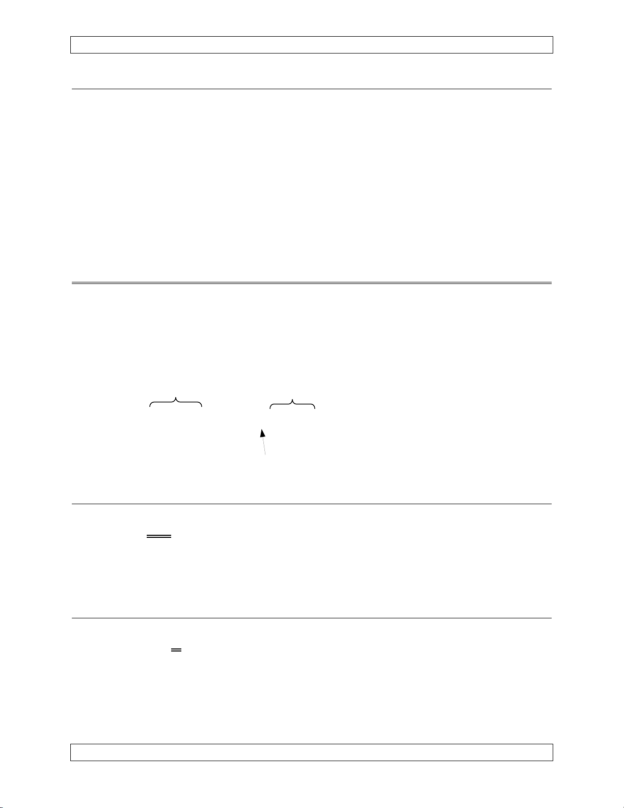
1.6 Unit Nomenclature
Tac/Com control heads are identified by two groups of numbers. The first defines the
general capability of the control head in terms of the total number of radios controlled
and type of display, and the second specifically defines the display filter and backlight
type, as well as the radio types supported. Each section of the part number defines part
of the control head capability.
General Capability Specific Interfaces
TH450 - 2NNFE
Display Filter Information
1.6.1 Series Designation
TH450 - 2NNFE
CH = Tac/Com I Series Controls
TH = Tac/Com II Series Controls Above example: Tac/Com II
1.6.2 Number Of Radios
TH250 - 2NN
2 = Two Radio Control
3 = Three Radio Control
4 = Four Radio Control Above example: 2 Radio
Jan 4, 2006 Page 1-13
ENG-FORM: 800-0108.DOT
CONFIDENTIAL AND PROPRIETARY TO NORTHERN AIRBORNE TECHNOLOGY LTD.
Page 22

Tac/Com Control Head Manual SM06 Rev. 4.10
1.6.3 Display Type
TH450 - 2FFNN
00 = LCD Display, Master (Discontinued)
10 = LCD Display, Slave (Discontinued)
50 = LED Display, Master
60 = LED Display, Slave Above example: LED Master
1.6.4 Display Filter/Lighting Suffix Information
TH260 - 2ZZ
0 = Yellow/Green LED Filter, or Clear LCD Filter, Natural 28 Vdc lighting.
(LCD Standard)
1 = Dark Green LED Filter, NVG-friendly LED 28 Vdc lighting
2 = Dark Green LED Filter, Natural 28 Vdc lighting. (LED Standard)
3 = Yellow/Green LED Filter w/Z-cloth, Natural 28 Vdc lighting
4 = Dark Green LED Filter, Natural 5 Vdc lighting
5 = Dark Green LED Filter, NVG-friendly LED 5 Vdc lighting
6 = Dark Green LED Filter, Blue/White 28 Vdc lighting
7 = Circular Polarized glass, daylight, Natural 28 Vdc lighting
8 = Circular Polarized glass, daylight, Blue/White 5 Vdc lighting
9 = Deep Red Filter with Red LED Displays, Natural 28 Vdc lighting
10 = Yellow/Green with Amber LED Displays, Natural 28 Vdc lighting
11 = Circular Polarized glass, daylight, NVG-friendly LED 5 Vdc lighting
12 = Circular Polarized glass, daylight, NVG-friendly LED 28 Vdc lighting
13 = Circular Polarized glass, Natural 5 Vdc lighting
14 = Dark Green LED Filter, Blue/White 5 Vdc lighting
15 = Circular Polarized glass, daylight, Blue/White 28 Vdc lighting
16 = Circular Polarized glass, daylight, NVIS B Compliant 28 Vdc lighting
17 = Circular Polarized glass, daylight, NVIS B Compliant 5 Vdc lighting
Page 1-14 Jan 4, 2006
ENG-FORM: 800-0108.DOT
CONFIDENTIAL AND PROPRIETARY TO NORTHERN AIRBORNE TECHNOLOGY LTD.
Page 23
SM06 Rev. 4.10 Tac/Com Control Head Manual
1.6.5 Interface-Specific Suffix Information
The position of the digit in the code reflects the position of the card in the control. The
code position from left to right equals the relevant card position from top to bottom.
TH450 - 2NNNE
A = ARINC 2 of 5 Comm M = Midland Syn-Tech I
B = Blank (No Controls) N = NAT NT-Series
C = Flitefone 40 O = Not Assigned
D = Motorola Astro/XTL Series P = RT9600/7200 Single Connector
D1 = Motorola Astro/XTL with zone function Q = RT9600 with Tones, No Guard
E = NT Slot. Controls only. No Card R = RT9600/7200 Plug Compatible
F = Flexcomm S = Motorola URC-200
G = Flex Slot. Controls only. No Card T = NAT NT-Series with Transcrypt
H = NTX Series with USFS Guard U = RT9600 with USFS Guard & Internal
I = Not Assigned 32 Tones
J = NAT Tac/Com NTX Series V = NAT NT-Series with USFS Guard
J1 = Chelton 805-1, 905-2, 915-1 W = Not Assigned
K = Midland Syn-Tech XTR X = Not Assigned
L = Motorola Spectra Y = Serial I/O Expansion Port
L1 = Motorola Spectra with zone function Z = General Slave Interface
Above example: 3 NAT & 1 Empty (Empty in bottom slot)
Earlier Tac/Com I controls had a different numbering scheme, using only a three
character suffix. If you need to convert an older number to a new one, contact NAT
for details, or consult revision 1.xx of this manual.
End of section 1
Jan 4, 2006 Page 1-15
ENG-FORM: 800-0108.DOT
CONFIDENTIAL AND PROPRIETARY TO NORTHERN AIRBORNE TECHNOLOGY LTD.
Page 24

Page 25

SM06 Rev. 4.10 Tac/Com Control Head Manual
Section 2 Installation
2.1 Introduction
Information in this section consists of: unpacking and inspection procedures, installation
procedures, post-installation checks, and installation drawings.
2.2 Unpacking and Inspection
Unpack the equipment carefully and locate the warranty card. Inspect the unit visually
for damage due to shipping and report all such claims immediately to the carrier
involved. Note that each unit should have the following:
Verify that all items are present before proceeding and report any shortage immediately
to your supplier.
2.2.1 Warranty
- Tac/Com Control Head
- Warranty Card
- Operator’s Manual
- Release certification
Complete the warranty card information and send it to NAT when the installation is
complete. If you fail to complete the warranty card, the warranty will be activated on
date of shipment from NAT.
Note: An appropriately rated facility, e.g. Certified Aircraft Repair Station, must install this
equipment in accordance with applicable regulations. NAT Ltd’s warranty is not
valid unless the equipment is installed by an authorized NAT Dealer. Failure to
follow any of the installation instructions, or installation by a non-certified individual
or agency will void the warranty, and may result in a non-airworthy installation.
2.3 Installation Procedures
2.3.1 Warnings
Do not bundle any lines from this unit with transmitter coax lines. Do not bundle any
lines from this unit with 400 Hz synchro wiring, or AC power lines. Failure to observe
these limitations may result in incorrect or intermittent operation, or severe audio
interference on received and transmitted signals.
In all installations, use shielded cable exactly as shown, and ground as indicated.
Significant noise problems and/or improper operation may result from not following
these guidelines.
Jan 4, 2006 Page 2-1
ENG-FORM: 805-0108.DOT
CONFIDENTIAL AND PROPRIETARY TO NORTHERN AIRBORNE TECHNOLOGY LTD.
Page 26

Tac/Com Control Head Manual SM06 Rev. 4.10
2.3.2 Cautions
All audio installations can be severely degraded by incorrect wiring and shielding, and
may result in much higher cross-talk, hum, and ground-loop interference. This should
be considered when installing audio wiring to and from the specific radio. Both the
audio Hi and Lo wires must be connected from the radios (audio outputs are floating
transformer windings on NT-series radios), and should be grounded only at the audio
panel via the audio common.
If multiple transceivers are installed, it is very beneficial to use tri-axial cable for the
antenna feedlines, with the outer shield grounded at the radio end only. This added
electro-static shielding greatly reduces cable coupling, and eliminates many types of
interference in the final installation. Observe proper antenna spacing and good routing
practice for all RF lines to avoid cross-talk, squelch interference, and phantom sidetone
problems.
2.3.3 Cabling and Wiring
All unshielded wire shall be selected in accordance with AC43.13-1B Change 1,
Paragraphs 11-76 through 11-78. Wire types should be to MIL-W-22759 as specified in
AC43.13-1B Change 1, Paragraphs 11-85, 11-86, and listed in Table 11-11. For
shielded wire applications, use Tefzel MIL-C-27500 shielded wire with solder sleeves
(for shield terminations) to make the most compact and easily terminated interconnect.
Follow the wiring diagrams in Section 2.9 as required.
Installation cabling must allow the unit to be easily withdrawn for disconnection, switch
and pot settings (internal), and removal. Ensure an adequate service loop is allowed in
the routing of the cable. This can become a serious problem if the unit is installed with
the cables so short that the unit cannot be removed without disassembly of the
mounting console. At least 1 foot (30 cm) of free cable is recommended.
Allow 3 inches (8 cm) from the end of the wire to the shield termination to allow the
hood to be easily installed. Note that the hoods supplied by NAT in installation kits are
'clamshell' hoods, and are installed after the wiring is completed.
Generally, all wiring should be at least 22 AWG, except power and ground connections,
which should be 20 AWG - check the appropriate Interconnect drawing for the unit
under consideration. Ensure that the ground connection is clean and well secured. To
prevent inadvertent system failure, power to this system must be supplied from a
separate breaker or fuse, and not bundled to any other source. A 1A breaker is
suggested (28 Vdc source).
Notes:
1. The case is grounded electrically and should be attached to a grounded surface
for correct RFI shielding. A pin is provided for grounding the case, and this must
be connected via its own wire to a suitable ground, not jumpered to the power
ground wire connection.
Page 2-2 Jan 4, 2006
ENG-FORM: 805-0108.DOT
CONFIDENTIAL AND PROPRIETARY TO NORTHERN AIRBORNE TECHNOLOGY LTD.
Page 27
SM06 Rev. 4.10 Tac/Com Control Head Manual
2. The interface cards for the RT9600 and RT7200 have different locks from those
on the original harness. The tight packaging on the Tac/Com control head does
not allow spring locks to be used. The harness locks must be changed to
jackscrews to match the Tac/Com connectors before flight. New locking
hardware is furnished with the control head when these cards are installed.
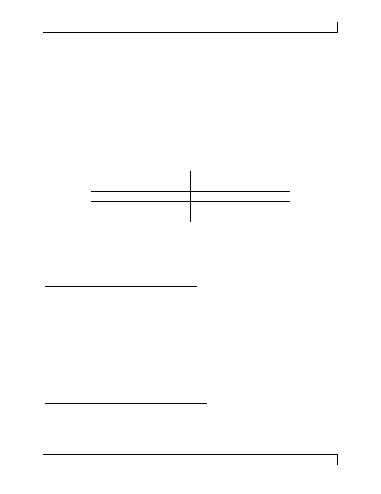
2.3.4 Mechanical Mounting
Installation should be in accordance with AC 43.13-1B chapter 7, sections 3 to 7 and
AC 43.13-2A chapter 2.
Mounting is accomplished in a standard Dzus rack or rail assembly with a clearance
opening of 5", and full width dimension of 5.75". The rail height required for mounting
the various control heads is shown below.
Tac/Com Series Rail Height Required
250/260 and 350/360 3.00"
450A 3.75"
450B and 460B 3.375"
450/460 4.875"
Be sure that adequate rear cable clearance is allowed when planning console
installations. Refer to the aircraft structural repair manual and maintenance manual for
instructions and information pertinent to this installation.
2.3.5 Notes
2.3.5.1 Control Head System Connector
The J100 System Connector Power/Lights/Ground connections must be provided for
operation of the overall system, in addition to the basic interface card-to-radio
connections. For specific RT9600/7200 radios, see the relevant Interface Card
supplement (SM06\PQRU\810-0) for an alternative method for providing these
connections to the control head.
Pins 7, 10 and 22 are serial data control lines that may be brought out to a connector for
serial loading of the control by a PC. This allows easy large scale data changes without
removing the control head from the aircraft. NAT provides a special software package
for this function. This port may also be used for Master/Slave operation or the DTE12
DTMF/Keyboard Data Unit.
2.3.5.2 Additional Mounting Considerations
LED display units come in several different display filter styles (see Section 1.6), and
the panel location and filter type should be matched for the best performance. LED
displays offer very wide viewing angles, and are suitable for centre console mounting
and locations not in the pilot's direct field of vision.
Jan 4, 2006 Page 2-3
ENG-FORM: 805-0108.DOT
CONFIDENTIAL AND PROPRIETARY TO NORTHERN AIRBORNE TECHNOLOGY LTD.
Page 28

Tac/Com Control Head Manual SM06 Rev. 4.10
2.4 Post Installation Checks
Before the unit is permanently mounted, perform the following functional tests and make
any needed adjustments and switch or jumper settings. Ensure that the unit is securely
mounted before any flight is attempted.
2.4.1 Voltage/Resistance Checks
DO NOT ATTACH THE TAC/COM CONTROL HEAD UNTIL THE FOLLOWING
CONDITIONS ARE MET.
With the Tac/Com control head disconnected from all of its mating connectors, make
the following measurements on the system connector P100 mating plug (25-pin)
whether it comes from an FC41 adapter cable or from the basic airframe wiring:
a) Check pins <1> and <2> for +28 Vdc relative to ground.
b) Check pins <13>, <14> and <15> for continuity to ground (below 0.5 ohms).
c) Check pin <3> (28 Vdc), pin <4> (14 Vdc) or pin <5> (5 Vdc) for proper lamp
dimmer voltage.
d) Check pin <16>, <17> or <18> for continuity to ground as above (lamp return).
If the control head uses only the RT9600/7200 plug-compatible interface card, it is
permissible to not use the system connector, and instead use the existing wiring from
the C-962/722. In that case, make the following checks on the C-962/722 25-pin audio
connector:
a) Check pin <19> for +28 Vdc relative to ground.
b) Check pins <10>, <12> and <20> for continuity to ground (below 0.5 ohms). Pin
<12> should be a separate wire to ground.
c) Check pin <16> (28 Vdc), pin <15> (14 Vdc) or pin <17> (5 Vdc) for proper lamp
dimmer voltage.
2.4.2 Power On Checks
WARNING:
High volume settings can cause hearing damage.
Set the headset volume control to the minimum volume
setting prior to conducting this test and slowly increase the
headset volume level to a comfortable listening level.
Power up the aircraft's systems with the Tac/Com control head and RT's installed, and
turn ON all of the radios and other accessories required for this system.
Page 2-4 Jan 4, 2006
ENG-FORM: 805-0108.DOT
CONFIDENTIAL AND PROPRIETARY TO NORTHERN AIRBORNE TECHNOLOGY LTD.
Page 29

SM06 Rev. 4.10 Tac/Com Control Head Manual
Make the following performance checks (refer to Section 3, Operation):
a) Confirm that the desired radios are installed in the assigned Tac/Com control
head slots (this data appears at power-up on the display). If any aspect of the
radio assignments is incorrect, or if messages such as 'waiting for slave' appear
when there is no slave, etc., the set-up of the control head may be incorrect.
Consult the Installation Configuration Mode section of this manual (Section 3.12),
or contact the Product Support department at NAT for instructions on how to alter
this data before proceeding.
b) Check for correct radio operation and channelling, both receive and transmit, and
ensure that all status indications are correct (TX and RX). Do not proceed until
the radios are operating correctly. It may be necessary to set the display screen
(after the last radio) on the control head to obtain a clear or bright display.
c) Correct squelch operation may require setting the AUDIO and FAST SQUELCH
pots on the top of the control head (NT-series radios only). The FAST pot is set
for the correct trigger point of the panel indicator (scan trigger point), and the
AUDIO pot is used to set the audible squelch threshold. These are factory set,
and any field adjustment may cause problems.
d) If squelch settings are to be made in the aircraft, use a calibrated signal
generator connected directly to the radio. The visual squelch indicator must be
set so that it appears at the same point as the audible squelch. Note that the
visual trip point (fast squelch) has no hysteresis, while the audible trip point will
remain tripped as the input level is decreased. This is normal and required for
correct operation.
e) If remote channel switches (Tac/Com II only) or a DTE12 (Tac/Com II only) are
installed, confirm that all remote channelling and editing functions are working.
All of these connections are via the system connector, J100/P100. DTE12 data
is serial, while the external remote switches are ground closures (pulled up to
+5 V internally).
f) Check each antenna feedline with a through-line wattmeter and suitable frequency
elements at the RT to ensure correct antenna matching. Reflected power in
excess of 25% represents a serious problem and should be investigated carefully,
or serious RFI and system interference as well as possible radio damage may
result. Check that forward power is to specifications for the radio in use.
Jan 4, 2006 Page 2-5
ENG-FORM: 805-0108.DOT
CONFIDENTIAL AND PROPRIETARY TO NORTHERN AIRBORNE TECHNOLOGY LTD.
Page 30

Tac/Com Control Head Manual SM06 Rev. 4.10
2.5 Troubleshooting
2.5.1 Weak Receive/Transmit, Intermittent Operation, Erratic Squelch
Ensure all antenna mounts are secure, cleanly grounded, and well terminated. Avoid
sharp coax cable bends or crushed coax from tie wraps. Never mount any antenna on
a composite surface unless a well-grounded and adequately sized (equal in radius to
the height of the antenna) ground plane has been provided. Keep antennas widely
separated, especially between VHF radios, and VHF and UHF radios. Bad antenna
matches and close proximity will result in large amounts of spurious radiation, which
may affect VHF-FM to VHF-AM operation and may result in harmonic interference
between VHF and UHF radios.
2.5.2 Strange Noises, No Receive Audio, Transmit Keying problems
Buzzes, hums or other background audio noises are symptomatic of multiple grounds or
noisy external systems such as inverters, blowers or pumps sharing wiring with the
audio system connections. Failure to key or correctly modulate a transmitter, or no
receive audio is often caused by not connecting all required grounds or wires to the
radio or external audio system. Check to make sure that the MIC AUDIO and PTT lines
are not reversed (keys, but no TX audio). Be sure both audio output wires are
connected from the transceivers (no or very faint RX audio).
A special caution is that no audio ground should be taken from the front instrument
panel or similar location that shares a ground return with a turn and bank or horizon or
other motor driven instrument. If this caution is not observed, the sound of the t&b
motor may be heard mixed in with receiver audio.
2.5.3 Some Frequencies Can't be Edited
Some frequencies are not really agile entries (such as crystal guard frequencies), and
as such should not be edited during normal operation. All such entries must be set via
the MASTER EDIT mode (see Section 3.11).
When in the SIMPLEX mode (RX and TX frequency lines display an 's'), you cannot edit
the TRANSMIT portion of the radio channel assignments because there is actually a
valid TRANSMIT frequency stored. It is temporarily hidden because of the SIMPLEX
function. To edit these frequencies, simply return the control head to DUPLEX
operation via the STATUS EDIT function or front panel switch, as appropriate.
2.5.4 Display Brightness is Too Low, Can't Increase to Full Brightness
The intensity of the display is set by two functions, the level set from the display screen
(advance the cursor past the last radio, then set the brightness up or down with the
SELECT switch) AND the status of the panel dimmer line. If the dimmer is active, then
the display automatically dims to HALF BRIGHTNESS of the previous setting. In some
Page 2-6 Jan 4, 2006
ENG-FORM: 805-0108.DOT
CONFIDENTIAL AND PROPRIETARY TO NORTHERN AIRBORNE TECHNOLOGY LTD.
Page 31

SM06 Rev. 4.10 Tac/Com Control Head Manual
aircraft, such as Aerospatiale airframes, there are two dimmers, one of which MUST be
ON for normal daylight flight, to drive engine instruments. If this line is accidentally
used, then the display will always be at half intensity. A dimmer must be used that is
OFF during normal daylight flying, and ON during night flying for correct control head
operation. Early control heads (prior to Tac/Com II) did not have this automatic feature,
which has been added to improve night visibility by reducing display glare in the cockpit.
2.5.5 Amber (RX) Squelch light comes on, but no RX audio is heard.
Press the HELP/SQ button. If audio is heard, this means there is a problem either with
the subaudible tones, or with the AUDIO squelch setting. Refer to the CTCSS or
Subaudible Tone Table in Section 3.5.4.2 of this manual to check the CTCSS tone
format and frequency, and/or refer to the Power On Checks section (2.4.2) to check the
audio squelch.
2.6 Final Inspection
During the test flight, check levels and operation of all functions. Display brightness or
contrast may have to be tailored for adequate viewing by the flight crew. Ensure there
is no interaction between any transmit functions and received NAVAIDS, or any other
communication receiver functions. Antenna placement or cable routing may have to be
changed if these problems are encountered. Closely spaced antennas or coax cable
runs may cause problems, especially between VHF systems (AM & FM), and between
VHF transmissions and UHF receiving (due to third harmonic relationship), particularly if
the RT406F (with its less selective front end) is used in a complex system.
Ensure that there is no interaction between Tac/Com control head operation and ADF
performance. If interference exists, relocation or re-routing of the interconnect cabling
may be required.
Before leaving the aircraft, ensure that all the mating connectors are securely fastened
to the Tac/Com control head. Also ensure that the unit is securely fastened to the
aircraft from the front panel, and that all Dzus fasteners are locked.
If all functions are satisfactory, the aircraft may be released for service once all required
log entries, electrical load and weight and balance amendments are made, the flight
manual supplement is updated, and the required local regulatory paperwork is
completed. There is currently no Technical Standing Order (TSO) for FM
Communication systems, regardless of manufacturer.
2.7 Continued Airworthiness
Maintenance of the Tac/Com Series control heads is ‘on condition’ only. Periodic
maintenance of this product is not required.
Jan 4, 2006 Page 2-7
ENG-FORM: 805-0108.DOT
CONFIDENTIAL AND PROPRIETARY TO NORTHERN AIRBORNE TECHNOLOGY LTD.
Page 32

Tac/Com Control Head Manual SM06 Rev. 4.10
2.8 Installation Drawings
This section has the complete interconnect drawing set for all installations, both current
and previous revisions. Be sure to use the correct drawings for your installation. Any
unique notes for a given installation type appear in the relevant Interface Card
Supplement and in Section 2.3.5. Consult this section for any information that may apply
to your specific installation.
All information for interface cards will be provided by Manual Supplements, available by
contacting NAT Ltd.
2.8.1 Outline drawings
DRAWING REV. DESCRIPTION TYPE
TH250\NF903 - Control head plan view (3.0") Mechanical
TH450\NNFF903 - Control head plan view (4.875") Mechanical
TH250\NN\905-0 1.01 Faceplate of Typical Tac/Com II, TH250 Faceplate
TH260\905-0 1.01 Faceplate of Typical Tac/Com II Slave, TH260 Faceplate
TH350\NNN\905-0 1.00 Faceplate of Typical Tac/Com II, TH350 Faceplate
TH360\905-0 1.10 Faceplate of Typical Tac/Com II Slave, TH360 Faceplate
TH450\NNNN\905 1.00 Faceplate of Typical Tac/Com II, TH450 Faceplate
TH460\905-0 1.01 Faceplate of Typical Tac/Com II Slave, TH460 Faceplate
CH200\NF905 - Faceplate of Typical Tac/Com I, CH200 (LCD) Faceplate
CH400\NNRR905 - Faceplate of Typical Tac/Com I, CH400 (LCD) Faceplate
2.8.2 System Connector (J-100)
DRAWING REV. DESCRIPTION TYPE
CH400-1\403-1 - Tac/Com I System Connector s/n 1001 – 1043 Interconnect
CH400-1\403-2 - Tac/Com I System Connector s/n 1044 – 1127 Interconnect
CH402-1\403 B Tac/Com I System Connector s/n 1127 and up Interconnect
TH402-1\403-0 1.03 Tac/Com II System Connector s/n 1001 and up Interconnect
CH410\403 B Tac/Com I Master-Slave Installation Interconnect
TH460\403 A Tac/Com II Master-Slave Installation Interconnect
TH460\403-1A A Tac/Com II Master-Slave Installation with DTE/DP12 Interconnect
CH400-1\405-1 - Tac/Com I System Connector s/n 1001 - 1043 Connector Map
CH400-1\405-2 - Tac/Com I System Connector s/n 1044 - 1127 Connector Map
CH402-1\405 B Tac/Com I System Connector s/n 1127 and up Connector Map
TH402-1\405 B Tac/Com II System Connector s/n 1001 and up Connector Map
Section 2 ends after these Drawings
Page 2-8 Jan 4, 2006
ENG-FORM: 805-0108.DOT
CONFIDENTIAL AND PROPRIETARY TO NORTHERN AIRBORNE TECHNOLOGY LTD.
Page 33

Page 34

Page 35

Page 36

Page 37

Page 38

Page 39

Confidential and Proprietary to NAT
Page 40

Page 41

Page 42

Page 43

Page 44

Page 45

Page 46

Page 47

Page 48

Page 49

Page 50

Page 51

Page 52

Page 53

Page 54

Page 55

Page 56

Page 57

Page 58

Page 59

Page 60

Page 61

Page 62

Page 63

Page 64

Page 65

Page 66

Page 67

Page 68

Page 69

Page 70

Page 71

Page 72

Page 73

Page 74

Page 75

SM06 Rev. 4.10 Tac/Com Control Head Manual
Section 3 Operation
3.1 Introduction
Information in this section consists of the functional and operating procedures for the
Tac/Com Control Heads.
3.2 General
To understand the operation of the Tac/Com control, a quick review of basic FM radio
operation is helpful here. It is normally a requirement to carry out the following general
operations on any FM radio system.
1. Turn the radio on and off.
2. Adjust the receive volume of the radio.
3. Select the required channel on the radio.
4. Optionally select/enable any special tones required for proper network
or repeater operation.
5. Optionally select/enable any guard receive or transmit functions.
It is also helpful to show visually that the radio is transmitting or receiving, so that the
pilot is assured of correct performance. If the radio is 'frequency agile' (i.e., the
frequency of operation can be set directly by the operator) a method must also be
provided to enter the specific frequency data, and identify and store the information.
Every manufacturer attacks these requirements in a different manner, and since the
Tac/Com system provides the ability to interface with other manufacturer's equipment
as well as NAT's own transceivers, a uniform method of operation must be provided.
How each common operating function is accomplished in the Tac/Com system is
described in the following sections. It is also possible to interrogate the control head
itself for help in learning how to operate it, simply by pressing the HELP button during
the first power-up screen or at any time while editing.
The on-line help function for the system is comprehensive enough to address most
operational questions, and corrects a long standing problem in the cockpit relating to lost
or missing operator's manuals. Every control function and valid editing choice is fully
explained through this system, which can be activated by pressing the HELP button.
It is important to remember that the many radios simultaneously controlled by the
Tac/Com system may have very different features and attributes as well as frequencies.
If the radio was incapable of some functions prior to connection to the Tac/Com head, it
will not suddenly acquire all the functions possible just by connection to the Tac/Com
control. Crystal controlled radios, such as the FliteFone 40, for example, do not
suddenly become agile radios, and Flexcomm radios don't scan simply because they
are connected to a Tac/Com control head. Only NAT's own radios offer full capability,
which includes extended tones, DPL, encryption, scanning and variable transmit power.
Jan 4, 2006 Page 3-1
ENG-FORM: 806-0106.DOT
CONFIDENTIAL AND PROPRIETARY TO NORTHERN AIRBORNE TECHNOLOGY LTD.
Page 76

Tac/Com Control Head Manual SM06 Rev. 4.10
3.3 Initial Operation
3.3.1 Power-up Help
Turn the Tac/Com system on by rotating any radio volume control away from the OFF
detent position. The software revision number will be briefly displayed, followed by a
screen presenting an option for use of the on-line HELP system, as shown below.
HE LP=Instruction
RADIO=Operation
If help is selected (i.e., the HELP button is pushed), the control head will present a
tutorial on the operation of each control head feature. To advance through the tutorial,
press HELP after reading each screen. To exit this initial help function at any time,
press the RADIO button, and the control head will begin normal radio operation.
3.3.2 Initial Operating Display
If help is declined (by using the RADIO button as directed), the control head will display
a summary of the installed functions and current settings for each radio (this feature can
be disabled in the installation set-up for faster start-up). Once all of the functions have
been displayed, the radio will be ready for normal operation.
Once normal control head operation is selected, the display will install the radio and its
settings as specified by the interface card and software set-up instructions. This will
produce the following system message on the control head:
NAT NT-150
Page 3-2 Jan 4, 2006
ENG-FORM: 806-0106.DOT
CONFIDENTIAL AND PROPRIETARY TO NORTHERN AIRBORNE TECHNOLOGY LTD.
Page 77

SM06 Rev. 4.10 Tac/Com Control Head Manual
NAT NT-150 or WULFS RT-7200 (etc.)
This is the radio type designated for that transceiver slot in the control head (RT1-4),
and will change if either the interface card, the stored software set-up or hardware
jumper selections are changed in the control head. This message is to advise what the
control head thinks should be in that interface slot.
Next, the status of the radio is presented which represents the state of its radio-wide
functions such as transmit power, duplex operation or tones. A summary of all the
selection options will be displayed, unless defeated in the installation software set-up to
speed up turn-on of the control head. This display will produce messages such as
those shown below, for each radio:
POWER=LO, TONES=OFF (etc.)
The control head will continue with each radio in sequence, and will finally position the
cursor (arrow) by the selected radio when it has finished. There may also be messages
such as those shown below, which are system error/alert messages reported by the
Tac/Com control head:
NO I/F BOARD
There is no interface card installed in this specific slot (RT1-4) inside the Tac/Com
control head. This message appears if there are empty slots in the control head, to
warn that the panel controls are inactive.
-- NO RADIO --
When tested by the Tac/Com control head, no radio was found installed in this specific
slot. It may have been removed for service, used in another aircraft, or have the
mating connector disconnected.
-- RADIO OFF --
When checked by the Tac/Com control head, the radio was found to be turned off or
defective (if turned ON at the front panel). This message also appears for Flexcomm
radios if they are removed from the aircraft, as they do not support the -- NO RADIO --
function.
3.4 Front Panel Controls
There are two main groups of controls, and a 2-, 3- or 4-line by 16-character display on
the Tac/Com control head. The first group of controls is 'radio specific', and affects the
operation of only a single radio (there can be up to four installed in a single control
head). The second are general controls that affect the over-all operation of the control
head. The function and relative location of these important groups is as follows:
Jan 4, 2006 Page 3-3
ENG-FORM: 806-0106.DOT
CONFIDENTIAL AND PROPRIETARY TO NORTHERN AIRBORNE TECHNOLOGY LTD.
Page 78

Tac/Com Control Head Manual SM06 Rev. 4.10
3.4.1 Radio Specific Controls
Radio-specific
Controls
Radio specific controls allow the general operation and function of each radio to be
modified independently. The radios are identified as 'RT1, RT2', etc. to the left of the
display, and the line of text continues through the display to connect to the specific
controls for that radio on the right hand side of the control head. The exact functions
that are provided on the front panel via the radio function switch will vary with each radio
type. Some radios support very few features, while others require both the front panel
switch, and a number of status line functions to set all of the radio functions. Guard
controls are not available on all units.
3.4.1.1 Guard Controls
Guard RX Volume
RX Status
Guard
Channel
In general, the GUARD volume control permits a zero volume level without turning the
radio off, but in some instances, such as USFS GUARD RX controls, this will not be
true. OAS government contracts require that this level not go to zero regardless of pot
setting, with a minimum fixed output at all times.
A second set of controls is provided for guard operation only when 'H', 'U' or 'V' interface
cards are installed. Note that the GUARD volume control has no OFF detent position.
Forcing the control fully counter-clockwise may cause switch damage. The internal
minimum guard volume adjustment is accessible through the right side of the control
head. The additional guard controls provide selection of the guard 1 and guard 2
channels, plus a separate RX status indicator.
Page 3-4 Jan 4, 2006
ENG-FORM: 806-0106.DOT
CONFIDENTIAL AND PROPRIETARY TO NORTHERN AIRBORNE TECHNOLOGY LTD.
Page 79

SM06 Rev. 4.10 Tac/Com Control Head Manual
3.4.1.2 RX (Receive) Volume Control
RX Volume
Controls
The RX volume control is adjusted via the round knob for each radio. Rotating this
control fully counter-clockwise to OFF turns the specific radio off. If all controls are
OFF, then the control head itself turns off.
3.4.1.3 RX/TX Status Indicator
RX/TX Status
Next to the volume controls are bi-colour indicators that display TX (Transmit) status or
RX (Receive) status. If that specific radio is keyed to transmit, the LED will be green. If
a signal is being received, the LED will be amber.
A radio that is receiving may still not produce any audio, if the tones or DPL codes for
that channel do not match the tones or DPL codes set in the control head. If tones are
set to ON for a given radio from the status line, then all data (frequency and tone/DPL
code) must be correct to hear the receive audio. If tones are OFF, then all incoming
transmissions are received. The indicator lights whether the logic is correct for audio or
not, to warn the pilot that channel is active with radio traffic of some kind.
If the radio is idle (not receiving or transmitting), the LED will be off. The colour coding
used for these functions corresponds to the existing indications used in the FF40, C-62
and C-1000, for pilot familiarity. It is worth noting that these conventions are reversed
from vehicular standards, and may be confusing for some emergency services staff
used to land mobile equipment. When used with a Wulfsberg radio equipped with a
guard channel, both the main and guard RX signal will illuminate the RX LED, unless
equipped with separate guard controls.
Jan 4, 2006 Page 3-5
ENG-FORM: 806-0106.DOT
CONFIDENTIAL AND PROPRIETARY TO NORTHERN AIRBORNE TECHNOLOGY LTD.
Page 80

Tac/Com Control Head Manual SM06 Rev. 4.10
3.4.1.4 Radio Mode Switch
Radio
Mode
Switch
The last radio specific control is the MODE or FUNCTION switch, which varies with the
type of radio used. For NT-series transceivers, it selects either NORM or SCAN modes
of operation, as specifically defined in the status line.
For NT-series transceivers scanning occurs at 90 channels/second/radio, and the
following scan modes (defined in the status edit mode) are:
LIST (up to a block of 32 channels/list).
PRIORITY (up to 2 priority channels + active monitor channel).
LIST+PRIORITY (2 priority + 30 channels in a given block).
Priority monitoring is 3 times/second for a 10-15ms sample. The radio will re-channel to
the priority channel if traffic is detected, and returns to the monitor channel (channel the
radio was resting on when scanning was selected) after a 2 second latency. All CTCSS
tones or DPL codes are inactive during scanning (due to lock delay).
With some radios, this mode switch is reserved for GUARD or MAIN transmit selection,
as scanning is not supported. It may also select SIMPLEX or direct (repeater talkaround) operation as opposed to NORM (Duplex) or repeater operation. Data for all
channels is stored as individual TX and RX frequencies, which permits them to be
entered and used in any way. The forced SIMPLEX function pushes the stored RX
frequency into the TX slot temporarily to permit 'talk-around' of an existing stored
repeater frequency, and avoids having to store a separate channel with this information.
3.4.2 General Controls - NORMAL Operation
The general control head functions include the switches that effect the over-all operation
of the control head. Some of these switches have dual functions depending on control
head mode of operation. The two modes of operation are NORMAL and EDITING.
Page 3-6 Jan 4, 2006
ENG-FORM: 806-0106.DOT
CONFIDENTIAL AND PROPRIETARY TO NORTHERN AIRBORNE TECHNOLOGY LTD.
Page 81

SM06 Rev. 4.10 Tac/Com Control Head Manual
The TOP ROW is for NORMAL OPERATION.
CHAN RADIO SQ
SELECT NEXT EDIT HELP
The BOTTOM ROW is for EDITING.
To show that they are related, engraved panel lines tie the EDITING functions together.
The alternate EDITING functions become active whenever the EDIT switch is in any
position other than OFF.
3.4.2.1 Display Switch
Display Switch
The DISPLAY switch works the same in both NORMAL and EDIT modes of operation.
The DISPLAY switch determines what data is shown on the individual channel
presentations for each radio. Either the alphanumeric channel name or identification (ID
position), or the actual channel frequency (RX and TX positions) can be displayed.
When editing, this also determines what will be edited. Whatever data is visible is the
material that can be edited. During normal operation, the crew can select whatever
presentation is the most helpful to them, which is generally the ID or channel name
display. The cursor, or left hand arrow, shows which radio is set up for channelling or
editing.
Jan 4, 2006 Page 3-7
ENG-FORM: 806-0106.DOT
CONFIDENTIAL AND PROPRIETARY TO NORTHERN AIRBORNE TECHNOLOGY LTD.
Page 82

Tac/Com Control Head Manual SM06 Rev. 4.10
3.4.2.2 CHAN -/+ Toggle Switch - NORMAL Operation
Channel Switch
To change channels, press the CHAN switch in the desired direction, either + for
ascending, or - for descending numbers. Channel selection can also be accomplished
remotely if the remote channelling switch is installed. The radio that has the cursor in
front of it is the one that will be channelled.
Channel numbers will increase from a02 upwards (a03, a04, etc.) with each press of the
switch to '+' position. If the switch is held to either position, it will scroll rapidly,
increasing in speed the longer it is held down.
3.4.2.3 RADIO Push Button - NORMAL Operation
Radio Pushbutton
This push button switch picks the active radio selected for any operation. The radio
selected is indicated by a triangular cursor to the left of the channel number (RT1 in this
example). Cursor movement is from top to bottom, to the brightness screen and then
returns back to the top again.
The radio that has the cursor in front of it is the one that will be channelled (RT1). To
select RT2, press RADIO. If pressed a second time, the display brightness screen will
be displayed.
When selected, a radio may be channelled, edited, or the manual squelch test operated. It
has no bearing on transmit or receive capability, and only serves as an indication of which
radio the control head is prepared to perform some operation on. This selection works in
increasing order only (1,2,3,4, display brightness), and then re-starts at the beginning.
Page 3-8 Jan 4, 2006
ENG-FORM: 806-0106.DOT
CONFIDENTIAL AND PROPRIETARY TO NORTHERN AIRBORNE TECHNOLOGY LTD.
Page 83

SM06 Rev. 4.10 Tac/Com Control Head Manual
3.4.2.4 EDIT Switch Function - NORMAL Operation
Edit Switch
When the EDIT switch is in the centre-off locked position, all editing functions are off,
and the control is in normal operation. It the switch is set to any other position, then
editing is active, and either radio or channel data can be altered by the operator.
3.4.2.5 Squelch Function - NORMAL Operation
HELP=Instruction
RADIO=Operation
Squelch
Pressing this button during the power-up screen presentation (when the control head is
first turned on) will take the operator through detailed help screens for each function of
the control head. In the normal operation of the control head, this is the only access to
help (on power-up), as this button is then the manual squelch (SQ) test button for the
selected radio.
The squelch test function is useful for monitoring activity on a radio when tones prevent
the squelch from opening normally, or to verify volume settings or radio function.
Pressing SQ over-rides all squelch logic, and lets the radio's raw receive signal pass to
the ship's audio system.
When the locking EDIT switch is in any position other than OFF (centre), the HELP
switch again becomes active, and provides context sensitive help for whatever function
is being attempted, such as frequency entry, tones or labelling.
These two modes of help (power on and edit) provide assistance to the pilot/operator
without interfering with the selected operation of the control head. If, basic help is
required after the Tac/Com control head is already on, cycle the control head off again
(turn all volume controls to OFF, or cycle the external breaker), and when powered up
again, the option for comprehensive help will re-appear.
Jan 4, 2006 Page 3-9
ENG-FORM: 806-0106.DOT
CONFIDENTIAL AND PROPRIETARY TO NORTHERN AIRBORNE TECHNOLOGY LTD.
Page 84

Tac/Com Control Head Manual SM06 Rev. 4.10
3.5 Editing
Editing is the general term for changing any information stored in the Tac/Com control
head.
There are two basic types of editing that can be selected from the front panel of the
control head. These are CH (channel) editing, and ST (status) editing. As the name
implies, channel editing permits channel data to be controlled by the operator. This
includes channel names, the transmit and receive frequencies and matching tones,
scan flags (for list scan) and for some radios, channel discrete lines. To edit different
channel information, such as frequency data or channel names, it is necessary to first
select which information (ID, RX, or TX) will be edited via the DISPLAY switch.
There is simply not enough room to fit every possible function switch that might be
needed for a given radio on the front of a Tac/Com control. Some radios also have
many more functions than others complicating this control arrangement. The solution
for this clutter is the use of the status line to show features that are important, but not
constantly in use on the front panel. Status functions can be as extensive as required
for a given radio. The internal editor permits only valid choices at all times, so that the
operator is not required to know a great deal about the specific radio in question, but
only what needs to be accomplished.
Editing Controls:
Two sets of legends exist for each of these switches. The bottom row (connected by
lines) represents the function of the switches during the edit mode of operation. It takes
some time to become familiar with the dual nature of these switches, but they greatly
reduce clutter on the front panel, and make it possible to package all of the required
functions into a size mechanically compatible with other systems.
Page 3-10 Jan 4, 2006
ENG-FORM: 806-0106.DOT
CONFIDENTIAL AND PROPRIETARY TO NORTHERN AIRBORNE TECHNOLOGY LTD.
Page 85

SM06 Rev. 4.10 Tac/Com Control Head Manual
3.5.1 Channel Editing
EDIT Switch
When the EDIT switch is in the CH position, the ID, RX, and TX information may be
edited. The position or character to be edited will flash or blink on and off. When
channel editing of data is in progress, operation of the radios is suspended, and the
dual function edit switches work in the following way:
3.5.1.1 SELECT Switch
SELECT
Switch
This switch is used to step the data entry up or down (+/-) on the currently marked radio.
The character that will be selected flashes. This flashing character is referred to as the
editing cursor, since it shows what is about to change. The intelligent editor within the
control head only permits a valid choice for every position for data entry. This is to aid
operators in reducing entry mistakes, particularly when busy with other flight
procedures.
The selection choices are strung together in a circle, and choices move through this
circle with the SELECT switch as shown below in the diagram:
Jan 4, 2006 Page 3-11
ENG-FORM: 806-0106.DOT
CONFIDENTIAL AND PROPRIETARY TO NORTHERN AIRBORNE TECHNOLOGY LTD.
Page 86

Tac/Com Control Head Manual SM06 Rev. 4.10
Depending on which way the SELECT switch is set (+ or -), the choices will move
around the circle in either direction. The editor removes numbers from this circle that
don't apply to the particular cursor position. For example, VHF High Band radios can
only have a 3, 4, 5, 6 or 7 in the 10's of MHz position, so no other numbers are
permitted during editing from the front panel in this location. Some radios do not
channel below 150 MHz, so then the editor removes the 3 and 4, and so on through
each position that can be edited.
When editing the channel ID label or name, the editor opens the circle to include all the
alphanumeric characters, and some frequently used symbols, like the blank (visible as a
flashing underline '_' to show the cursor location), slash (/) and number sign (#). The
choices for selection are shown below:
3.5.1.2 NEXT Switch
NEXT
Switch
This push button switch cycles the editing cursor from left to right to the next character
to edit. The editor will change what choices are valid as the cursor moves from one
character to the next.
Sometimes more than one character will flash. This is because the only valid choices
involve two characters, such as the fractional kHz entry for a channel frequency. This is
also true for tone code entries. The SELECT switch will then scroll through the
available entries from an internal table.
Page 3-12 Jan 4, 2006
ENG-FORM: 806-0106.DOT
CONFIDENTIAL AND PROPRIETARY TO NORTHERN AIRBORNE TECHNOLOGY LTD.
Page 87

SM06 Rev. 4.10 Tac/Com Control Head Manual
Note that a STAR appears at the right side of the RT #2 ID label in the diagram below.
This means that the channel discrete line is enabled for that channel. This is a line to
control external switching of a special function. It is programmed just like a scan flag,
by advancing to that position with the NEXT button, and then toggling the entry with the
SELECT switch. There is only one channel discrete line to set, and it appears only for
the Flexcomm radios. This is a seldom-used function, and is provided for compatibility
reasons only.
3.5.1.3 EDIT Switch
EDIT
Switch
This locking, centre-off switch shifts the operation of the control head from editing back
to the normal operating mode. For normal radio operation, it must be returned to the
centre or OFF position. No special activity is needed to store the data that has been
entered while editing. It is stored as soon as it is entered. When editing is finished, set
the EDIT switch back to OFF.
3.5.1.4 HELP Switch
HELP
Switch
The help screen may be accessed at any time, and for any function, while in the edit
mode. Press the HELP button if the operation of any function is unclear during editing.
Information will be provided for the desired edit function, and if pressed while channel
editing in the tone character position, will bring up the complete tone look up table for
reference.
Jan 4, 2006 Page 3-13
ENG-FORM: 806-0106.DOT
CONFIDENTIAL AND PROPRIETARY TO NORTHERN AIRBORNE TECHNOLOGY LTD.
Page 88

Tac/Com Control Head Manual SM06 Rev. 4.10
3.5.2 Summary of Channel Editing
For each channel stored in the control head, there are three possible data entries;
identification label (ID), receive frequency (RX) and transmit frequency (TX). If
equipped, the radio may also have tone and scan information associated with these
entries. Note that non-agile radios can still have frequency data entered in the master
edit mode (for reference only), but changing this data will have no effect on radio
operation.
The ID label or channel name has no effect on radio operation, and is provided for
operator/pilot convenience in identifying the selected channel. Any alphabetical
character, the numbers 0-9, and some punctuation (space # . - / ) may be inserted in the
ID label.
Help can be used at any time when editing, to give instruction for the operation being
performed. The exact data that pressing HELP provides depends on the current
activity, as it is context-sensitive. Editing tone locations and pressing HELP will bring
up the tone look-up table. Editing channel frequencies will bring up frequency
information, and so on.
It is important to remember that while frequency data may be edited, the radio itself
must be an agile radio, with the AGILE MODE ENABLED on the interface card for any
change to actually take place. Crystal controlled radios, or PROM coded radios which
allow editing of this data in the master edit mode (for reference only), will not change
frequency after editing. Receive frequency editing is also allowed for guard channels
(also crystal controlled) used in some radios, but again, this is for reference only, and no
change will take place in the operation of the radio.
When editing RX or TX frequency data, only those frequencies the control head
recognizes as valid can be entered, and only in the fractional multiples allowed. If
mismatched multiples occur when editing, a warning message, FREQ ERROR will
appear, because the RX and TX frequencies must both be divisible by the same
synthesizer interval.
The last positions (far right hand) on the RX and TX lines are for tone data (these
locations have scan flags on the ID line). Depending on the type of radio installed,
differing codes are possible here to represent the CTCSS (or sub-audible) tones used
for repeater or squelch control. A different tone can be set for receive and transmit. the
capability to have tones can also be enabled or disabled through the status lines,
providing the radio will support this function. If the tones are enabled (via the status
line), an '=' (equal sign) will be displayed between the channel number and following
information on all three presentations. If the special function, DPL, or Digital Private
Line has been enabled at installation time, then 83 different 3 digit DPL codes are
available for use with NT-series radios.
Page 3-14 Jan 4, 2006
ENG-FORM: 806-0106.DOT
CONFIDENTIAL AND PROPRIETARY TO NORTHERN AIRBORNE TECHNOLOGY LTD.
Page 89

SM06 Rev. 4.10 Tac/Com Control Head Manual
r
k
3.5.3 Summary of Channel Labels
Tac/Com permits two kinds of channel numbers (set at installation time) for ease of use
and as a memory aid. Block numbers begin with a letter, a-d, and have 32 channels per
block. This allows channels to be grouped together for convenience (i.e., all channels
for forestry in one block, all EMS in another, all police in another, etc.), and also clearly
shows which channels can be scanned together as a group. NAT NT-series radios hold
32 channels at one time for scanning, and they must be from the same block. Block
numbers are a reminder of which channels are grouped together.
Blocks: a01-a32 Sequential Numbers: 001-032
b01-b32 033-064
c01-c32 065-096
d01-d32 097-128
The control head can also be set to show 128 sequential channels (or some lesser
number, if preferred, and if it has been set up that way at installation time). In this case,
the channel numbers go 001 to 128. This is often used with Flexcomm radios, where
there is no scan function.
There is also one additional mode, which is supported only on the NT136-PAS multimode transceiver. In this case, channel numbers are labelled A01 to A64 and F01 to
F64. The 'A' channels are AM, and the 'F' channels are FM. Each 32-channel block
may be scanned within each bank (1-32 and 33-64), but all channels must be AM or FM
within the scan group.
Blocks: A01-A32 Sequential Numbers: 001-032
A33-A64 (equivalent) 033-064
F01-F32 065-096
F33-F64 097-128
In addition to using the front panel channel and radio switches, the remote channel and
radio switches may also be used, if installed. They work exactly the same way as the
front panel switches.
A DTE12 or DP12 can also be used to access a channel directly by number. In this
case, just key in the number (sequential number) and press the ENTER key on the
DTE12. It is important to understand how channel numbers work, because some things
may occur on the display that might be confusing. An example is shown below,
demonstrating what happens when the control head is channelled below a01.
> REPROGRAMMING
127=FORESTRY * -
Note that the control displays the message
REPROGRAMMING while it re-loads the next
block of 32 channels into the NAT radio fo
scanning. This happens very quickly, but creates
a short pause when scrolling through each bloc
of 32 channels.
Jan 4, 2006 Page 3-15
ENG-FORM: 806-0106.DOT
CONFIDENTIAL AND PROPRIETARY TO NORTHERN AIRBORNE TECHNOLOGY LTD.
Page 90

Tac/Com Control Head Manual SM06 Rev. 4.10
As soon as the data is loaded into the radio, the next channel in the next block appears
(d32). Channels wrap around from highest to lowest, so that it is never necessary to
reverse direction to advance to any channel.
3.5.4 Summary of Subaudible Tones
Subaudible tones are sometimes used to screen unwanted transmissions on shared
frequencies. They are often referred to as PL Tones or Private Line Tones. The correct
name defined by the Telecommunications Industry Association (TIA) is Continuous
Tone Controlled Squelch System (CTCSS).
Tac/Com has stored a useful tone look-up table inside the help function. To view it, edit
a channel and move the editing cursor (flashing character) to the far right hand position
where the tone should be. Pressing HELP there will allow the CTCSS tone table to be
reviewed.
3.5.4.1 Methods of Tone Display
Over the years, many different codes have come into existence to describe these tone
sub-audible tone frequencies. They are listed below:
Tone Frequency (FREQ): - This is the TIA standard.
This is a frequency below 300 Hz that uniquely identifies the tone key that is
used to control the radio squelch (allows audio to be heard), or control a repeater
function. There are only three digits available on the control head for this data,
so any decimal fraction is omitted from the display (i.e., 103.5 Hz becomes 103).
Although not displayed, the correct frequency is still used.
EIA Codes (1-32):
This is a sequential number from 1-32 (or 38) that identifies the tone in order
from lowest (67.0 Hz) to highest (203.5 Hz or 250.3 Hz), as defined by the
Electronics Industry Alliance (EIA).
Wulfsberg Codes (WCODES):
These are sequential shifted OCTAL codes based on the thumbwheel design of
the C-1000 control. Because they are missing numbers ending in 0 & 9, they are
often confused with the straight sequential number for the EIA tones.
Motorola Codes (MCODES):
These are alphanumeric codes that seem largely random in assignment, but
often appear in the land mobile business if Motorola equipment is used.
Page 3-16 Jan 4, 2006
ENG-FORM: 806-0106.DOT
CONFIDENTIAL AND PROPRIETARY TO NORTHERN AIRBORNE TECHNOLOGY LTD.
Page 91

SM06 Rev. 4.10 Tac/Com Control Head Manual
3.5.4.2 CTCSS or Subaudible Tone Table
The following table shows the relationship of the supported tone codes. All of these are
available in the control head, and when editing, the SELECT slew switch (+/-) will bring
up only valid choices for each type of code. Pressing HELP while editing these
positions of the channel data will bring up the tone table for reference. The Frequency
shown will have the decimal fraction truncated when displayed on the control head.
Tone Frequency 1-32 (1-38) WCODE MCODE
67.0 Hz 1 01 XZ
71.9 Hz 2 02 XA
74.4 Hz 3 03 WA
77.0 Hz 4 04 XB
79.7 Hz 5 05 SP
82.5 Hz 6 06 YZ
85.4 Hz 7 07 YA
88.5 Hz 8 08 YB
91.5 Hz 9 11 ZZ
94.8 Hz 10 12 ZA
97.4 Hz 11 13 ZB
100.0 Hz 12 14 1Z
103.5 Hz 13 15 1A
107.2 Hz 14 16 1B
110.9 Hz 15 17 2Z
114.8 Hz 16 18 2A
118.8 Hz 17 21 2B
123.0 Hz 18 22 3Z
127.3 Hz 19 23 3A
131.8 Hz 20 24 3B
136.5 Hz 21 25 4Z
141.3 Hz 22 26 4A
146.2 Hz 23 27 4B
151.4 Hz 24 28 5Z
156.7 Hz 25 31 5A
162.2 Hz 26 32 5B
167.9 Hz 27 33 6Z
173.8 Hz 28 34 6A
179.9 Hz 29 35 6B
186.2 Hz 30 36 7Z
192.8 Hz 31 37 7A
203.5 Hz 32 38 M1
210.7 Hz (NAT) 33 (NAT ONLY) 41 (NAT ONLY) M2 (NAT ONLY)
218.1 Hz (NAT) 34 (NAT ONLY) 42 (NAT ONLY) M3 (NAT ONLY)
225.7 Hz (NAT) 35 (NAT ONLY) 43 (NAT ONLY) M4 (NAT ONLY)
233.6 Hz (NAT) 36 (NAT ONLY) 44 (NAT ONLY) M5 (NAT ONLY)
241.8 Hz (NAT) 37 (NAT ONLY) 45 (NAT ONLY) M6 (NAT ONLY)
250.3 Hz (NAT) 38 (NAT ONLY) 46 (NAT ONLY) M7 (NAT ONLY)
The multiple codes shown are available on current generation Tac/Com II controls only.
Previous generation Tac/Com I & II controls had only a single code, which was the
WCODE, for compatibility with existing aircraft transceivers.
Jan 4, 2006 Page 3-17
ENG-FORM: 806-0106.DOT
CONFIDENTIAL AND PROPRIETARY TO NORTHERN AIRBORNE TECHNOLOGY LTD.
Page 92

Tac/Com Control Head Manual SM06 Rev. 4.10
The additional codes and frequency display were added in the new control head
software in 1991 for USFS/OAS contracts. Tone data is often received in the EIA
sequential number format, or as the raw frequency, and requires additional tone support
for ease of use. Controls with USFS interfaces (guard controls) are set for the EIA
sequential tone code at the factory. Older controls (pre-1991 Tac/Com II) may upgrade
to current generation software for this expanded tone display.
3.5.4.3 Using Help to Get the Table
The tone code table is accessed by pressing HELP while editing a tone location during
channel editing. Scroll through the table by pressing HELP until the desired entry is
located. Press RADIO to exit, or continue through the table by pressing HELP until the
data entry screen is reached.
3.5.4.4 DPL Codes
NAT NT-series transceivers support 83 Digital Private Line Codes (DPL) in addition to
the CTCSS or Private Line subaudible tones. This option must be enabled at installation
time in the installation and configuration mode of operation. It is normally shipped set to
OFF by the factory to reduce confusion over tone codes.
DPL codes are three digit sequences that describe a digital code sent at low frequency
in the background of regular transmissions. They are filtered out of normal receive
audio and provide another method of signalling or squelch control.
Code numbers are arbitrary and are stored in an internal table. When in use, the
control head finds the correct entries based on how the code is entered. The FREQ
option for tone presentation is not available if DPL is enabled.
023 DPL Code If the '0' position is chosen for edit, the control head is
programmed to select a 3-digit DPL code and bring up the
table for the SELECT switch to choose from.
32 Tone Code If the first digit position is skipped, the control head is tone
code programmed to select a 2-digit CTCSS tone code and
bring up the table for selection.
This arises ONLY if DPL is enabled. For most users, this selection will not be used
because only subaudible tones are used.
Page 3-18 Jan 4, 2006
ENG-FORM: 806-0106.DOT
CONFIDENTIAL AND PROPRIETARY TO NORTHERN AIRBORNE TECHNOLOGY LTD.
Page 93

SM06 Rev. 4.10 Tac/Com Control Head Manual
=
3.6 Status Line Editing
The status lines for each radio contain all the extra functions supported by the radio.
Because this is largely defined in software, it also provides a very cost-effective method
of upgrading the system performance or features through simple software (EPROM)
changes, rather than radical panel re-design. Some radios may have little or no
function support (such as the FliteFone 40), others may have many features (such as
NT-series RT's) including power level shift, scan, tones, and priority.
Like editing other data, only allowable options are presented, guided by the control
head’s reading of the interface card's capability and the stored software installation set
up routines. This mode can also be used to display the status of the radio quickly,
without editing any data.
To edit status line data, press the RADIO button until the triangular cursor appears to
the left of the radio whose status is to be edited or displayed. Once the radio is
selected, ST(status) EDIT mode may be entered to change the information.
In this mode, each of the available functions for the radio can be set, or reviewed. Only
valid functions and choices will be presented. Note that for this radio, the TX mode
function is set for DUPLEX operation. Pressing NEXT will advance to the next function,
while pressing SELECT will select what choice is wanted for this function.
Jan 4, 2006 Page 3-19
ENG-FORM: 806-0106.DOT
CONFIDENTIAL AND PROPRIETARY TO NORTHERN AIRBORNE TECHNOLOGY LTD.
Page 94

Tac/Com Control Head Manual SM06 Rev. 4.10
=
3.6.1 NEXT and SELECT Switch Use
SIMPLEX This choice will cycle with the SELECT switch.
TX MODE This function will cycle with the NEXT switch.
Cycling SELECT will change the choice displayed for any given function.
To advance to the next function, press NEXT, and it will appear. Use the SELECT
switch to again insert the desired option, and continue in this manner until the radio
status is correctly defined. If NEXT is pressed again, the functions will cycle around
again in a loop to allow for any error corrections. The pattern of this selection is shown
below to illustrate the flow of information:
The specific functions that appear in this general loop vary with each transceiver type,
and to some extent, the version of the software. New generation Tac/Com II controls
have three scan modes, while older ones have only two. This can be upgraded by
replacing the EPROM in an older control head.
Page 3-20 Jan 4, 2006
ENG-FORM: 806-0106.DOT
CONFIDENTIAL AND PROPRIETARY TO NORTHERN AIRBORNE TECHNOLOGY LTD.
Page 95

SM06 Rev. 4.10 Tac/Com Control Head Manual
To illustrate the choices possible in the STATUS EDIT MODE, the following diagram
shows all the current options and choices for an NT-series transceiver. While this
appears complicated as a chart, it is very simple to use and just represents a sequence
of clear choices that cycle around for user selection.
When editing is finished, return the EDIT switch to OFF, and the information will be
stored. It is not necessary to go through the entire status listing, and exit is available at
any time. This feature may also be used to check how the radio is set up without
making any changes.
3.6.2 Status Edit Features
The status edit features currently implemented in Tac/Com are as shown and explained
below:
3.6.2.1 TX MODE=
There are two modes possible, either DUPLEX (REPEATER) operation, or SIMPLEX
(DIRECT) operation. This determines whether a common frequency is used for RX and
TX, or whether different frequencies will be used. This function over-rides what is
stored in the individual channel data locations, and allows those stored channels to also
be operated in SIMPLEX mode without taking up another storage location. Not all
radios have this capability.
3.6.2.2 TONES=
Most radios have this capability. TONES can be set ON or OFF for the radio by this
function, thus enabling or disabling any tones which may be set on a per channel basis
through channel editing. NAT NT-series radios and the RT-96/7200 also support a
tones mode of TX ONLY, which enables only the transmit tone, but not the receive tone.
Jan 4, 2006 Page 3-21
ENG-FORM: 806-0106.DOT
CONFIDENTIAL AND PROPRIETARY TO NORTHERN AIRBORNE TECHNOLOGY LTD.
Page 96

Tac/Com Control Head Manual SM06 Rev. 4.10
This is used where the tones are needed only to open the repeater and serve no RX
squelch function.
3.6.2.3 POWER=
Some radios, such as NAT's NT-series and the RT-9600/7200 support a high and low
power transmitter function. Many radio station licenses have power restrictions at
altitude, and must be set to low TX power above 5,000' for legal operation. This may
also be required to prevent repeater interference at altitude, or to permit secure
operations.
3.6.2.4 TONE DISP=
New generation software now permits the user to define the tone presentation to suit
local operations on a radio-by-radio basis. This selection can be set to the tone
frequency referred to as FREQ, or to one of several codes. The sequential numbers for
the first 32 EIA tones are referred to as 1-32. The alphanumeric codes for Motorola
radios are referred to as MCODES. The shifted octal codes used by Wulfsberg are
referred to as WCODES on the status line.
To select the desired tone display option from the list, chose the desired display mode
with the SELECT switch. The options are 1-32, WCODE, MCODE and FREQ. Note
that the FREQ option will not appear if the DPL tones have been selected ON in the IAC
edit mode. Refer to Section 3.5.4.4 for more information.
3.6.2.5 SCAN=
For NAT series transceivers, the option of scanning a LIST, PRIORITY channels, or on
newer generation control heads, LIST + PRIORITY is provided. The Scan List channels
are edited in the second last digit on the ID line from normal channel edit mode. For
more details on scanning refer to Section 3.9.
3.6.2.6 P1=, P2=
The Priority 1 and 2 channels are selected by toggling the CHAN +/- switch. Two
channels are selected for each bank of channels (a through d). When the scan option is
selected to List, the priority channels are not active but are retained in memory.
3.6.2.7 GUARD RCVR=
The RT-9600 guard functions can be from either the front panel (U interface), or the
status line, depending on which type of interface has been installed in the control head.
If the status line is used (R or P interface) the line appears as GUARD=0 (off), 1, or 2.
For Flexcomm, the guard RX may only be enabled or not from the status line, as only
one channel exists. Front panel guard functions refer to guard transmit operation.
Page 3-22 Jan 4, 2006
ENG-FORM: 806-0106.DOT
CONFIDENTIAL AND PROPRIETARY TO NORTHERN AIRBORNE TECHNOLOGY LTD.
Page 97

SM06 Rev. 4.10 Tac/Com Control Head Manual
3.6.2.8 PWR-UP CHAN=
This is the channel the control head will go to when it is powered up. This may be set
for each radio. On early Tac/Com I controls, only a specific channel could be set, but
current generation Tac/Com I & II motherboards have additional non-volatile memory to
remember the last channel used, and so can also provide an option of returning to the
last channel set prior to power down. This channel is referred to as the PDC or Power
Down Channel, and can be set as an option instead of any specific channel number.
3.6.2.9 ENCRYPTION=
NAT NTX138 radios are available with an encryption option. If installed in the radio the
control head will include a status line to allow the selection of encryption 'on' or 'off'.
3.7 Channel Display Summary
The NAT Tac/Com control heads provide three displays for each channel of stored radio
information as set by the DISPLAY switch at the lower left side of the control head.
3.7.1 Display Switch Set to 'ID'
ID or Channel Label Information. This is a name, such as FORESTRY, HOSPITAL or
BASE 5. The display format shows the CHANNEL number, ID LABEL, and any SCAN
FLAGS.
A typical ID Label might look like this:
a01= FORESTRY sc
Channel Label Scan Flag
The '=' indicates that TONES ARE ENABLED. This appears only once the tones are
turned ON from the STATUS EDIT function. Tones can be stored, but not active, and
can be activated for TX ONLY, or both TX and RX, as required. TX ONLY is the normal
mode for forestry operations on USFS/OAS/BLM contracts. If all tones (both RX and
TX) are activated, no audio may be heard in some simplex operations, as no tones may
be present, and thus the radio squelch will not open.
SCAN FLAGS indicate which channels are flagged for monitoring during LIST SCAN.
Another flag can appear here, the PRIORITY SCAN FLAG for the P1 and P2 channels,
but this data is set from the STATUS EDIT function, as it can exist only once for each
radio, or once for each bank (NT-series radios). Both list & priority scan are supported
in NAT NT-series radios, and can be programmed by the operator. For Flexcomm
radios, a CHANNEL DISCRETE flag ([) can also be programmed, to be used for special
external switching. It appears in the same place as the SCAN FLAG on the display.
Jan 4, 2006 Page 3-23
ENG-FORM: 806-0106.DOT
CONFIDENTIAL AND PROPRIETARY TO NORTHERN AIRBORNE TECHNOLOGY LTD.
Page 98

Tac/Com Control Head Manual SM06 Rev. 4.10
NAT NTX138 radios provide wide-band and narrow-band operation. The bandwidth flag
indicates the selected mode. It indicates the current modulation acceptance and
transmit deviation mode. When a
wide-band mode. When a
character is displayed the channel is operating in narrow-
character is displayed the channel is operating in
band mode
A typical NTX138 ID line might look like this
a01= FORESTRY
Channel
Label
Bandwidth
Flag
sc p
1
Scan
Flags
3.7.2 Display Switch Set to 'RX'
RX or Receive Frequency and Tone. This is the receive frequency of a given channel,
plus its Receive Tone (if any), displayed in the format selected previously.
A typical RX frequency might look like this:
a01= 156.875r 91
Channel RX Freq. Tone
The '=' indicates that tones are enabled from the STATUS EDIT function. The small 'r'
indicates that the data displayed is a RECEIVE frequency. If the radio is put into the
simplex mode, this will be replaced with an 's'. In SIMPLEX or DIRECT operation, the
radio's TX frequency is shifted to the RX frequency, to permit talk-around operation on
repeaters. The old data remains in the control head memory, but is not displayed.
3.7.3 Display Switch Set to 'TX'
TX or Transmit Frequency and Tone. This is the transmit frequency of a given channel,
plus its Transmit Tone (if any), in the format selected previously.
A typical TX frequency might look like this:
a01= 154.775t 100
Channel TX Freq. Tone
The '=' indicates that tones are enabled from the STATUS EDIT function. The small 't'
indicates that the data displayed is a transmit frequency. If the radio is put into the
simplex mode, this will be replaced with an 's', and the TX frequency cannot be edited.
In SIMPLEX or DIRECT operation, the radio's TX frequency is shifted to the RX
frequency, to permit talk-around operation on repeaters. The old data remains in the
control head memory, but is not displayed.
Page 3-24 Jan 4, 2006
ENG-FORM: 806-0106.DOT
CONFIDENTIAL AND PROPRIETARY TO NORTHERN AIRBORNE TECHNOLOGY LTD.
Page 99

SM06 Rev. 4.10 Tac/Com Control Head Manual
3.8 Changing Display Brightness
There is one additional display function, which is the INTENSITY/CONTRAST setting.
On LED controls, this is selected by advancing the cursor past the bottom radio. The
display brightness screen below will be shown. On a two radio control, simply press the
RADIO button two times if the cursor is set to the top radio, or once if set to the bottom
radio, and the screen below will appear. The display brightness is adjusted with the
SELECT switch. Press RADIO again to return to normal operation.
CHAN - = Dimmer
CHAN + = Brighter
On LCD controls, there are two ways of making this adjustment, either by the screen
described above, or by a DISPLAY/CONTRAST pot, if there is adequate room on the
front panel. The Contrast control changes the contrast ratio and viewing angle of the
LCD to suit varying light and position situations. If the display is subjected to dramatic
temperature extremes (hot or cold), it will alter the chemical properties of the display,
and may require an adjustment of this control to return the appearance to the desired
presentation.
3.9 Scanning
Scanning is an automatic internal function that rapidly samples radio channels under
operator control. The operator may select one of several predefined modes that control
how the radio will carry out this function (via the STATUS EDIT function), and has a
front panel switch to send the radio into this mode of operation.
Scanning is very useful for checking radio traffic on one or more channels, while
working a 'home' or monitor channel (the one the radio was on before scanning was
selected). When scanning is active, all CTCSS/Subaudible Tone or DPL Functions are
ignored, and with the NT150, the radio does not test for these conditions when
determining that a channel has been found. Tones remain active for squelch control.
This is because the delay to test for tones is so long compared to the radio lock-up time,
that scanning would be seriously compromised. NT-series transceivers scan at rates of
Jan 4, 2006 Page 3-25
ENG-FORM: 806-0106.DOT
CONFIDENTIAL AND PROPRIETARY TO NORTHERN AIRBORNE TECHNOLOGY LTD.
Page 100

Tac/Com Control Head Manual SM06 Rev. 4.10
approximately 90 channels/second. It takes almost half a second to provide tone or
DPL decoding, which would result in virtually useless scanning of 2 channels/second. It
is therefore recommended that when using either the NT150 or
the NTX138, the tones
should be turned off to prevent slow scanning.
When Scanning is active, the front panel CHAN switch is inactive (for that radio),
because channel control is taken over by the scanning logic in the control head. This
may cause some operator confusion if the control head has acquired a channel (while
scanning) and manual channel change is attempted. No change will occur, and the
radio must be selected out of SCAN into NORM operation for manual channel changes
to work from the panel control.
If the microphone for a transceiver is keyed while the control head is scanning, the radio
will be rechannelled to the 'home' or monitor channel for transmission.
When scanning, a signal needs to be slightly stronger than during normal operation
because the time interval for detection is so short. No tones or DPL codes are taken
into account when scanning. The radio will stop on any scan-designated channel that
has an RF signal present, but received audio may not be heard if the tones are
incorrectly set in the control head. To avoid any confusion, tones can be set to OFF (via
the status edit function) during scanning so that all channels will be heard.
Any channel can be designated as both a PRIORITY channel and a LIST channel within
the 4 banks of 32 channels supported by NAT NT-series transceivers. The appropriate
scan flags will then appear after the channel name in the ID mode (P1, or P2, and/or
SC). Any or all of the 32 channels in a bank can be in the list for LIST SCANNING, but
only one channel each may be assigned the P1 and P2 Priority designation.
NOTE: NAT NTX138 radios provide 128 continuous channels. Therefore there can be
only one pair of priority channels selected.
When scanning is selected by the front panel mode switch, a message will be displayed
to indicate what the radio is doing. On earlier Tac/Com controls, this message was
'SCANNING', but in new software revisions, the scan mode and bank are now displayed
for better operator understanding. These messages are now as follows:
Display
Scan Mode
L -SCANNING 'a' LIST SCANNING, bank 'a'
P -SCANNING 'b' PRIORITY SCANNING bank 'b'
LP-SCANNING 'c' LIST+PRIORITY SCANNING bank 'c'
Page 3-26 Jan 4, 2006
ENG-FORM: 806-0106.DOT
CONFIDENTIAL AND PROPRIETARY TO NORTHERN AIRBORNE TECHNOLOGY LTD.
 Loading...