

Page 1

Spectra T200, T380, T680,
T950, and T-Finity
Drive Installation or Replacement
SpectraLogic.com
Page 2

Copyright Copyright © 2008 – 2013 Spectra Logic Corporation. All rights reserved. This item and the
information contained herein are the property of Spectra Logic Corporation.
Notices Except as expressly stated herein, Spectra Logic Corporation makes its products and
associated documentation on an “AS IS” BASIS, WITHOUT WARRANTY OF ANY
KIND, EITHER EXPRESSED OR IMPLIED, INCLUDING BUT NOT LIMITED TO
THE IMPLIED WARRANTIES OF MERCHANTABILITY OR FITNESS FOR A
PARTICULAR PURPOSE, BOTH OF WHICH ARE EXPRESSLY DISCLAIMED. In no
event shall Spectra Logic be liable for any loss of profits, loss of business, loss of use or
data, interruption of business, or for indirect, special, incidental or consequential
damages of any kind, even if Spectra Logic has been advised of the possibility of such
damages arising from any defect or error.
Information furnished in this manual is believed to be accurate and reliable. However, no
responsibility is assumed by Spectra Logic for its use. Due to continuing research and
development, Spectra Logic may revise this publication from time to time without notice,
and reserves the right to change any product specification at any time without notice.
Trademarks BlueScale, CarbideClean, Python, RXT, Spectra, SpectraGuard, Spectra Logic, TeraPack,
T-Finity, TranScale, the CarbideClean logo and the Spectra Logic logo are registered
trademarks. Endura, EnergyAudit, and Tape without Pain are trademarks of Spectra
Logic Corporation. All rights reserved worldwide. All other trademarks and registered
trademarks are the property of their respective owners.
Part Number 91010010 Revision C
Revision
History
Revision Date Description
A November 2008 Initial release
B May 2010 Added the T-Finity library
C April 2013 Added LTO-6 and TS1140 technology drives
Contacting
Spectra Logic
To Obtain General Information
Spectra Logic Website: www.spectralogic.com
United States Headquarters European Office
Spectra Logic Corporation
Phone: 1.800.833.1132 or 1.303.449.6400
International: 1.303.449.6400
Fax: 1.303.939.8844
Spectra Logic Technical Support
Technical Support Portal: support.spectralogic.com
United States and Canada
Phone:
Toll free US and Canada: 1.800.227.4637
International: 1.303.449.0160
Email: support@spectralogic.com
Mexico, Central and South America, Asia, Australia, and New Zealand
Phone: 1.303.449.0160
Email: support@spectralogic.com
Spectra Logic Europe Ltd.
Phone: 44 (0) 870.112.2150
Fax: 44 (0) 870.112.2175
Europe, Middle East, Africa
Phone: 44 (0) 870.112.2185
Email: support@spectralogic.com
Deutsch sprechende Kunden
Phone: 49 (0) 6028.9796.507
Email: spectralogic@stortrec.de
To Obtain Documentation
Spectra Logic Website: www.spectralogic.com/documents
April 2013 Drive Installation or Replacement—Spectra T200, T380, T680, T950, and T-Finity Library
2
Page 3

DRIVE INSTALLATION OR
REPLACEMENT
This guide provides instructions for either installing an additional drive or
replacing an existing drive in a Spectra T200, T380, T680, T950, or T-Finity
library (the library).
Task
Prepare for Maintenance page 5
Continuing or Stopping Backups page 5
Ensuring ESD Protection page 5
Gathering Tools and Supplies page 6
Replace or Install a Drive page 9
Preparing the Library page 9
Accessing the Drives page 12
Removing the Malfunctioning Drive page 14
Determining Drive Sled Adaptor
Requirements
Installing the Drive page 17
page 15
Complete the Procedure page 20
Resolving Firmware Mismatches page 20
Connecting the Cables page 21
Testing the Drive page 25
Installing the Cover or Securing the
Rear Door
Adding the Drive to a Partition page 26
Restarting Backups page 26
Return the Component page 27
page 26
3
Page 4

Illustrations The replacement drive that you received may not look
exactly like the drives shown in this document.
Most of the figures in this guide show the Spectra T380 library. The relative
locations of the components and the procedures are the same for the other
libraries unless otherwise indicated. The differences are indicated by
library type; for example:
Spectra T200, T380, or T680—items indicated with this text refer to any
one of these three libraries.
Spectra T950 and T-Finity—items indicated with this text refer to
either of these two libraries.
User Interface Updates The BlueScale user interface changes as new
features are added or other modifications are made between software
revisions. Therefore, the user interface screens on your library may differ
from those shown in this document.
Drive Bay Assemblies Each drive is mounted on a drive sled which is
installed in a drive bay assembly (DBA) in the back of the library. If there
are no empty drive bays in your library, you must install a new DBA to
accommodate additional drives.
Tape Drive Support This table shows the tape drives supported by the
individual libraries.
Library LT O - 3 LT O - 4 LT O - 5 LT O - 6 TS1140
technology
T200 YYYY N
T380 YYYY N
T680 YYYY N
T950 YYYY N
T-FinityNYYY Y
April 2013 Drive Installation or Replacement—Spectra T200, T380, T680, T950, and T-Finity Library
4
Page 5

Prepare for Maintenance Continuing or Stopping Backups
PREPARE FOR MAINTENANCE
Make sure you fulfill the prerequisites described in this section and
familiarize yourself with all the sections in the document before starting.
Continuing or Stopping Backups
Use the following guidelines if you are installing or replacing a drive in a
drive bay assembly (DBA) already in the library.
Robotic Control
Path
QIP or RIM
(all libraries)
Direct-attached
Fibre Channel drive
(Spectra T200,
T380, T680)
Note: Selecting a drive to provide the robotic control path is part of configuring a partition. Refer to
the library’s User Guide for more information.
Description
Backups running to all other drives in the library (or partition) can safely
continue while you install a new drive or replace an existing one.
Backups running to other drives in the library (or partition) can safely continue
while you install a new drive or replace an existing one, unless the drive you are
replacing is the one exporting the library (that is, providing the robotic control
path for the partition). If the drive you are replacing provides the control path
for the robotics, stop backup operations to the partition.
Note: T950 and T-Finity libraries do not support using a direct-attached drive
to provide the robotic control path.
Ensuring ESD Protection
The repair environment for the library must be free of conditions that
could cause electrostatic discharge (ESD). To protect the library from ESD,
follow these procedures when repairing or testing the library:
Place a static protection mat on the work surface used while removing
and installing library components. Use a 1-megohm resistor to ground
the static protection mat.
Wear a static protection wrist band whenever you handle library
components that have been removed from their antistatic bags. Connect
this wrist band to the static protection mat or to other suitable ESD
grounding.
Keep all electronic components in antistatic bags when not in use.
April 2013 Drive Installation or Replacement—Spectra T200, T380, T680, T950, and T-Finity Library
5
Page 6
Prepare for Maintenance Gathering Tools and Supplies
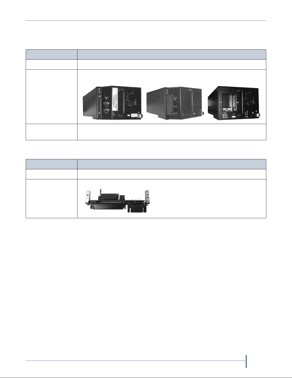
Fibre Channel SCSI
tape drive example tape drive example
TS1140 technology
tape drive example
Gathering Tools and Supplies
You must have the following to complete this procedure:
Item Description
Supplies ESD protection equipment
A Replacement
Drive from Spectra
Logic
To ol s
T200 and T380 only
A #2 Phillips screwdriver
You need the following if you need to install a drive sled adaptor. See
Determining Drive Sled Adaptor Requirements on page 15.
Item Description
To ol s A #1 Phillips screwdriver
Drive Sled Adaptor
(PN 90948360)
Understanding Component Identifiers
Each drive in the library has a unique drive component identifier.
Drives are identified in the library’s BlueScale user interface using the
format shown in the following sections.
Spectra T200, T380, or T680 Library on page 7
Spectra T950 or T-Finity Library on page 8
April 2013 Drive Installation or Replacement—Spectra T200, T380, T680, T950, and T-Finity Library
6
Page 7
Prepare for Maintenance Understanding Component Identifiers
QIP
QIP
QIP
Drive 4
Drive 3
Drive 1 Drive 2
Drive 4
Drive 3
Drive 1 Drive 2
Drive 4
Drive 3
Drive 1 Drive 2
DBA 3
DBA 2
DBA 1
3
2
1
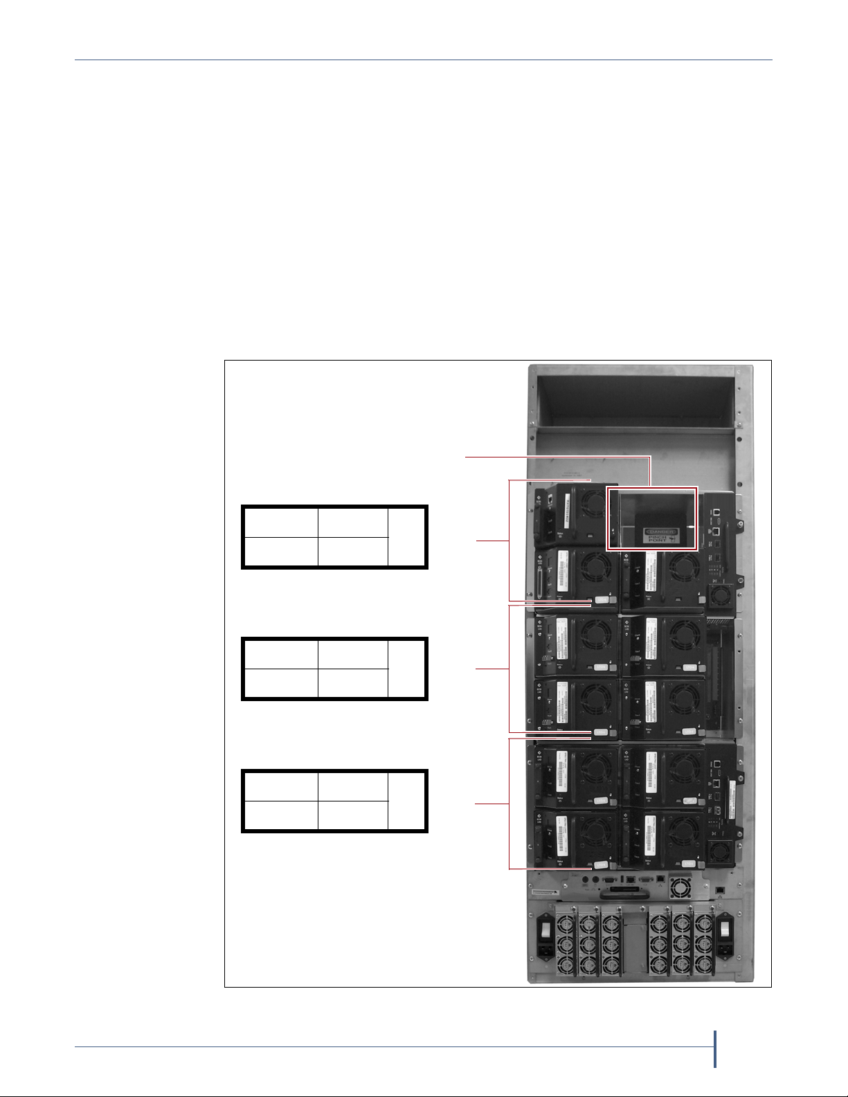
This figure shows the relationship between the
DBA number and the drive locations used in
the identifier.
Back panel drive locations and
their identifiers (T380 shown)
Drive bay
opening
Spectra T200, T380, or T680 Library The BlueScale software
component identifier for drives has the form DBAx/Y-DRVx:
DBAx
is the number of the drive bay assembly (DBA) containing the
drive
; a DBA holds up to four drives and one Quad-Interface
Processor (QIP) or Robotics Interface Module (RIM
).
Y is the drive type.
fLTO refers to a Fibre Channel LTO drive.
LTO refers to a SCSI LTO drive.
DRVx is the number of the drive bay in the DBA, as viewed from the
back of the library.
Example If a Fibre Channel drive is installed in DBA2, drive position 4,
its identifier is DBA2/fLTO-DRV4.
April 2013 Drive Installation or Replacement—Spectra T200, T380, T680, T950, and T-Finity Library
7
Page 8
Prepare for Maintenance Understanding Component Identifiers
QIP
QIP
QIP
Drive 4
Drive 3
Drive 1 Drive 2
Drive 4
Drive 3
Drive 1 Drive 2
Drive 4
Drive 3
Drive 1 Drive 2
DBA 3
DBA 2
DBA 1
3
2
1
QIP
Drive 4
Drive 3
Drive 1 Drive 2
4
QIP
Drive 4
Drive 3
Drive 1 Drive 2
5
QIP
Drive 4
Drive 3
Drive 1 Drive 2
6
Frame 1
DBA 4
DBA 6
DBA 5
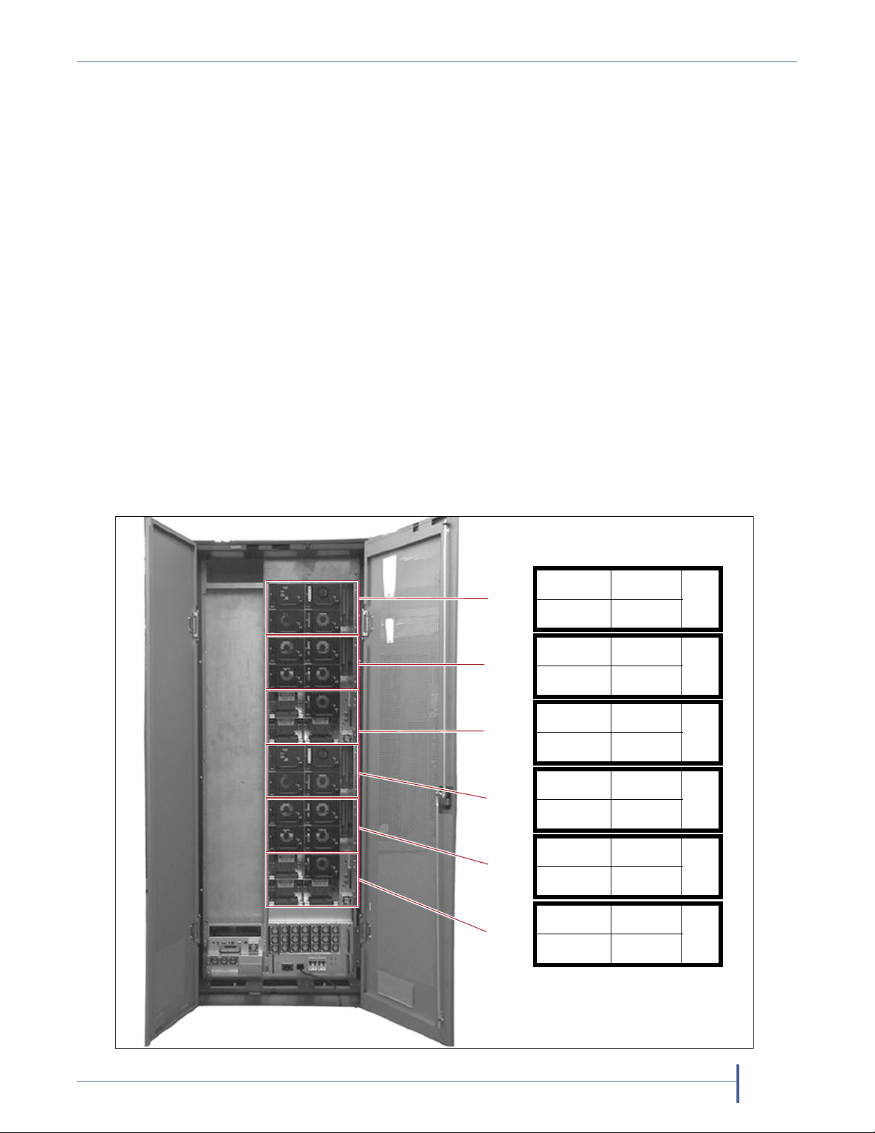
Back panel drive locations and
their identifiers (T950 shown)
(optional)
(optional)
(optional)
Spectra T950 or T-Finity Library The BlueScale software component
identifier for drives has the form FRx/DBAx/Y-DRVx:
FRx is the number of the frame from left to right when viewed from
the front of the library.
DBAx is the number of the drive bay assembly containing the drive;
a DBA holds up to four drives. If the optional DBAs shown in the
photo are replaced by TeraPack Bay Assemblies, the top DBA
becomes DBA 3.
Y is the drive type
fLTO refers to a Fibre Channel LTO drive.
LTO refers to a SCSI LTO drive.
fTS11x0 refers to a Fibre Channel TS1140 technology drive.
DRVx is the number of the drive bay in the DBA.
This figure shows the relationship between the DBA number and the
drive locations used in the identifier. The relationship between the DBA
number and drive locations is the same for each additional drive frame.
Example If a Fibre Channel drive is installed in frame 1, DBA2, drive
position 4, its identifier is FR1/DBA2/fLTO-DRV4.
April 2013 Drive Installation or Replacement—Spectra T200, T380, T680, T950, and T-Finity Library
8
Page 9
Replace or Install a Drive Preparing the Library
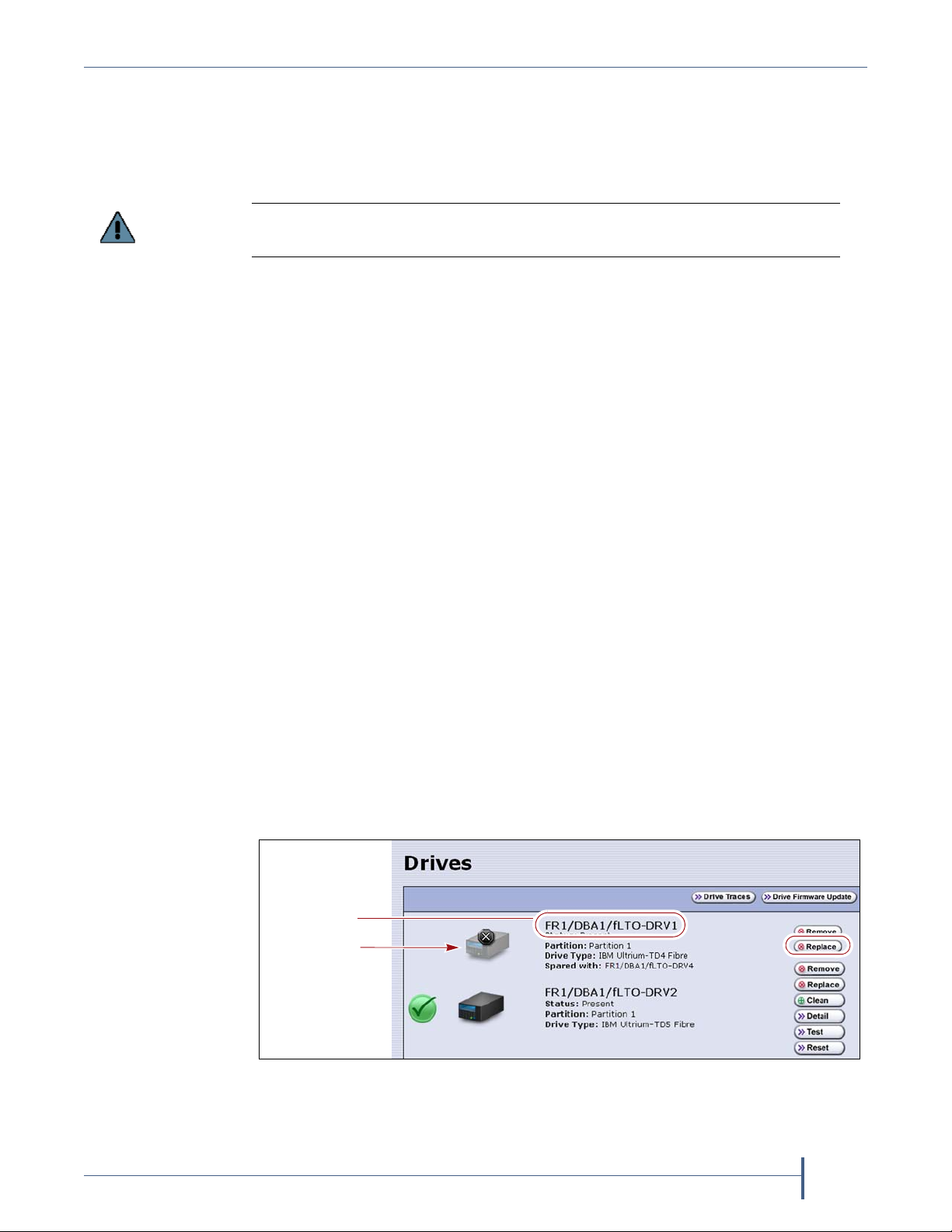
Important
Failed drive
Component
Identifier
REPLACE OR INSTALL A DRIVE
The following sections describe how to replace an existing tape drive or
install an additional tape drive:
When replacing a drive, the new drive must be the same type (interface and
generation) as the one you replace.
Preparing the Library
Prepare the library to add or replace a drive using the appropriate
instructions:
Drive Replacement Preparation on page 9
—OR—
Drive Installation Preparation on page 11
Drive Replacement Preparation
Your backup software, the library, or both may indicate a drive problem.
Identify the problem drive and then check the Drives screen on the library
user interface for the drive’s component identifier.
If the malfunctioning drive contains a cartridge, attempt to use the backup
software or BlueScale user interface to move the cartridge to an empty slot
before replacing the drive. See your library’s User Guide for instructions. If
you are unable to remove the cartridge, continue with the replacement
without removing the cartridge.
After you determine which drive needs replacing, follow these steps to
shut down the drive so that you can remove it from the library.
1. Log into the library with superuser or administrator privileges.
2. Select Configuration > Drives (or DLM). The Drives screen displays.
Figure 1 The Drives screen.
9
April 2013 Drive Installation or Replacement—Spectra T200, T380, T680, T950, and T-Finity Library
Page 10

Replace or Install a Drive Preparing the Library
Important
Status LED
Important
3. Click Replace for the drive that you want to replace.
Do not click Remove. This option permanently removes the drive from the
partition. When the replacement drive is installed, it will not be assigned to the
partition from which the malfunctioning drive was removed.
If you click
partition will be deleted.
Remove and the selected drive is the only drive in the partition, the
A Feedback Required screen prompts you to confirm that you want to
replace the drive.
4. Determine the physical location of the failed drive, either by looking for
the drive sled status light that blinks amber or by using the drive’s
component identifier displayed on the Drives screen.
Figure 2 The drive sled (Fibre Channel drive sled shown).
5. Click OK.
Another Feedback Required screen indicates that the requested drive
has been successfully shut down.
Do not respond to the prompt in the Feedback Required screen or perform any
other operations from the user interface (either locally or remotely) until you
complete the replacement procedure. Responding before you replace the drive will
power on and configure the drive you just powered down.
6. Proceed to Accessing the Drives on page 12.
April 2013 Drive Installation or Replacement—Spectra T200, T380, T680, T950, and T-Finity Library
10
Page 11
Replace or Install a Drive Preparing the Library
Important
Drive Installation Preparation
This section describes how to prepare to add a new drive to the library.
1. Log into the library with superuser or administrator privileges.
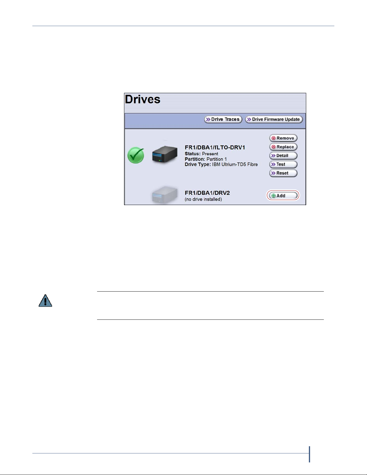
2. From the toolbar menu, select Configuration > Drives (or DLM). The
Drives screen appears.
Figure 3 The Drives screen.
3. Click Add next to the location where you want to add a drive.
A Feedback Required screen prompts you to confirm that you want to
add the drive.
4. Click OK.
Another Feedback Required screen indicates that the library is ready
for you to install the new drive.
Do not respond to the prompt in the Feedback Required screen or perform any
other operations from the user interface (either locally or remotely) until you
complete the drive installation.
April 2013 Drive Installation or Replacement—Spectra T200, T380, T680, T950, and T-Finity Library
11
Page 12

Replace or Install a Drive Accessing the Drives
Cover
Knurled
screw
Alignment nut
Accessing the Drives
This section describes how to access the tape drives.
Spectra T200 or T380 Remove the rear panel cover (if present) in order to
install or replace drives.
1. Using your fingers or a #2 Phillips screwdriver, loosen the two knurled
screws securing the bottom of the cover to either side of the chassis.
Figure 4 The rear panel cover and screws (T380 shown).
2. Lift the cover upward and away from the chassis to disengage the two
nuts extending from the back of the cover from the holes on either side
of the chassis. Set the cover aside.
Figure 5 Cover alignment nuts (one on each side).
April 2013 Drive Installation or Replacement—Spectra T200, T380, T680, T950, and T-Finity Library
12
Page 13

Replace or Install a Drive Accessing the Drives
Handle
Lock
(tilt up and out
to disengage)
Drive
1. Lift
2. Turn
Empty
drive bay
Spectra T680 The T680 is shipped and installed in a rack. Access the back
of the rack and open the door. You may need to unlock the handle first.
Figure 6 The T680 rack door handle.
Spectra T950 or T-Finity The drives are shielded by protective doors.
1. Locate the door handle on the back of the library.
2. Lift the handle and turn it either direction to disengage it and open the
library doors. You may need to unlock the handle first.
Figure 7 The back of the library (T950 shown).
April 2013 Drive Installation or Replacement—Spectra T200, T380, T680, T950, and T-Finity Library
13
Page 14

Replace or Install a Drive Removing the Malfunctioning Drive
Unlock drive
Remove drive
Removing the Malfunctioning Drive
Note: If you are installing an additional tape drive, skip to
Determining Drive Sled Adaptor Requirements on page 15.
Follow these steps to remove a drive:
1. Locate the drive, as described in Drive Replacement Preparation on
page 9.
2. Make sure that the Status LED (see Figure 2 on page 10) is blinking
amber, indicating that the drive is powered off.
3. Carefully disconnect any cables from the drive.
Note: Label the cables before you disconnect them so you can
reconnect them to the same locations on the new drive.
4. Unlock the drive by pushing the drive lock inward.
Note: Depending on the type of drive, the drive lock may look
different from the one shown in Figure 8.
Figure 8 Releasing the drive lock and removing the drive.
April 2013 Drive Installation or Replacement—Spectra T200, T380, T680, T950, and T-Finity Library
14
Page 15

Replace or Install a Drive Determining Drive Sled Adaptor Requirements
Caution
Hold the cable of
the adjacent Fibre
Channel tape drive
out of the way
while removing
or installing a
tape drive.
Note: the Fibre
channel connector
on your tape drive
may not look the
same as the one
shown here.
Caution
5. If the drive you are removing is adjacent to another drive, hold the
other drive’s cables out of the way as you remove the failed drive.
If your Fibre Channel tape drive has the connectors on the side, as shown in
Figure 9, ensure that you hold the Fibre Channel cable of the adjacent Fibre
Channel tape drive out of the way to prevent damaging the cable.
Figure 9 Hold the cables out of the way.
6. While supporting the bottom of the drive sled, pull outward on the
drive sled handle to remove the drive from the library.
The drive sled weighs approximately 15 lb. (7 kg). Be careful not to drop it.
When removing the drive, be careful not to damage or dislodge any cables
connected to adjacent drives.
7. Set the drive aside for return to Spectra Logic. See Return the
Component on page 27.
Determining Drive Sled Adaptor Requirements
There are two types of Drive Bay Assemblies (DBAs) in the field. Certain
drives require an adaptor to fit in one style of DBA, but not the other. If
your installation requires an adaptor, one will be include in the shipping
materials.
Note: This section is not applicable if you are replacing an LTO-4 or
earlier generation drive.
April 2013 Drive Installation or Replacement—Spectra T200, T380, T680, T950, and T-Finity Library
15
Page 16

Replace or Install a Drive Determining Drive Sled Adaptor Requirements
Part number
Part number
The original Drive Bay Assembly (DBA), part number 90948021, requires
an adaptor, part number 90948360, on the bottom of TS1140 and LTO-5 and
later generation tape drives for connection with the DBA.
The Ethernet DBA, part number 90948496, uses a different connector that
will not mate with the adaptor.
TS1140 and LTO-5 and later generation tape drives with adaptors
need the drive adaptors removed before they are installed into an
Ethernet DBA.
TS1140 and LTO-5 and later generation tape drives without
adaptors need adaptors installed before they are installed in the
original DBAs.
LTO-4 and earlier generation tape drives are only supported in the
original DBA.
DBA LTO-4 and earlier
drive
generations
Original DBA
(has blue and black
drive connectors)
Ethernet DBA
(has black drive
connectors)
No adaptor
required
Not supported No adaptor
LTO -5 an d l ate r
drive
generations
Adaptor
required
required
TS1140
technology
Adaptor
required
No adaptor
required
Use the following steps to identify if a drive sled adaptor is needed and to
install or remove an adaptor.
1. Determine the type of DBA that is in the library by looking at the drive
connectors. The original DBA has blue and black connectors. The
Ethernet DBA has only black drive connectors.
If needed, you can also determine which style DBA is in the library by
checking the part number sticker in the controller bay.
Figure 10 The original DBA, part number
90948021, with black and blue connectors.
April 2013 Drive Installation or Replacement—Spectra T200, T380, T680, T950, and T-Finity Library
Figure 11 The Ethernet DBA, part number
90948496, with black connector only.
16
Page 17

Replace or Install a Drive Installing the Drive
2. Based on the DBA type, and the type of drive you are replacing, remove
or install the drive adaptor as needed.
Note: The drive adaptor ships in a different box than the drive.
For the original DBA (Figure 10) with black and blue connectors
(part number 90948021), install the adaptor on the bottom of LTO-5
and later generation and TS1140 technology drives, if not present.
a. Carefully plug the adaptor into the bottom of the drive. The
connector is keyed and will only fit one way (Figure 13).
b. Using a #1 Phillips screwdriver, secure the adaptor with the two
screws provided (Figure 12).
For the Ethernet DBA (Figure 11) with black connectors only (part
number 90948496), remove the adaptor on the bottom of LTO-5 and
later generation and TS1140 technology drives, if present.
a. Using a #1 Phillips screwdriver, remove the two screws securing
the adaptor in place (Figure 12).
b. Carefully remove the adaptor as shown (Figure 13).
Figure 12 Two screws secure the
adaptor.
Figure 13 The adaptor connector only
fits one way.
Installing the Drive
Follow the steps in this section to install a tape drive in your library.
1. Refer to Drive Replacement Preparation on page 9 to determine where
to install each drive.
If the library includes QIPs—a drive must be installed in the same
DBA as the QIP that will connect it to the network.
If the library uses direct-attached Fibre Channel drives for the
robotic control path—installing the drives sequentially, beginning
with the next available drive bay, simplifies the configuration. For
example, if drive 1 is in drive bay 1, install drive 2 in drive bay 2,
and so forth. The T950 and T-Finity libraries do not allow using
direct-attached drives for the robotic control path.
April 2013 Drive Installation or Replacement—Spectra T200, T380, T680, T950, and T-Finity Library
17
Page 18

Replace or Install a Drive Installing the Drive
Important
Hold the cable of
the adjacent Fibre
Channel tape drive
out of the way
while removing
or installing a
tape drive.
Note: the Fibre
channel connector
on your tape drive
may not look the
same as the one
shown here.
Caution
2. Remove the drive from its protective packaging.
3. While supporting the bottom of the drive sled, slide the new drive into
the empty drive bay (Figure 15). Push the drive in until an audible click
indicates that it has locked into place.
If your Fibre Channel tape drive has the connectors on the side, as shown in
Figure 14, ensure that you hold the Fibre Channel cable of the adjacent Fibre
Channel tape drive out of the way to prevent damaging the cable.
Figure 14 Hold the cables out of the way.
The drive sled weighs approximately 15 lb. (7 kg). Be careful not to drop it.
Be careful not to damage or dislodge any cables connected to adjacent drives.
Figure 15 Installing the drive sled into the library.
April 2013 Drive Installation or Replacement—Spectra T200, T380, T680, T950, and T-Finity Library
18
Page 19

Replace or Install a Drive Installing the Drive
4. Return to the Feedback Required screen displayed on the user interface
(see Step 5 on page 10 for a replacement drive, or Step 4 on page 11 for
a new drive) and click OK.
The next step depends on whether you are installing a new drive or
replacing a drive.
Replacement drive—The library powers on the replacement drive
and begins the process of configuring it.
New drive—If you installed a new drive, you need to add the new
drive to a partition before it can be used (see Adding the Drive to a
Partition on page 26). New drives added to the library display an
orange square icon with a “?”, indicating that the drive is not part of
any partition.
When the configuration is complete, the Drives screen refreshes to
show the status of the newly installed drive.
Figure 16 The Drives screen after adding a drive.
5. Repeat Step 2 through Step 4 for each additional drive.
April 2013 Drive Installation or Replacement—Spectra T200, T380, T680, T950, and T-Finity Library
19
Page 20

Complete the Procedure Resolving Firmware Mismatches
System Status icon
COMPLETE THE PROCEDURE
Follow the steps in this section to complete the installation or replacement
procedure.
Resolving Firmware Mismatches
When the new drive completes its power on sequence, the library may
display a firmware mismatch error. Determine the type of firmware
mismatch and update the firmware as necessary.
DCM Firmware Mismatch All components in the library should be at the
same library package level. Check the system messages to for any firmware
mismatch messages associated with the drive you just installed or
replaced.
To check the system messages, login to the BlueScale user interface and
click the System Status icon on the status bar.
Figure 17 The System Status icon.
If a DCM firmware mismatch is displayed in the System Messages after the
new drive powers on, then:
If the current BlueScale package is 11.x or greater, run Package Update
to re-apply the current library package, which will update any noncompliant components. See the BlueScale Package Update Instructions for
more information. In most cases this will upgrade the DCM firmware,
in some cases it will downgrade the DCM firmware.
For libraries running BlueScale 10.x or earlier, contact Spectra Logic
Technical Support (see Contacting Spectra Logic on page 2) before
running Package Update.
April 2013 Drive Installation or Replacement—Spectra T200, T380, T680, T950, and T-Finity Library
20
Page 21

Complete the Procedure Connecting the Cables
Important
Important
Drive Firmware Mismatch Use the instructions in your User Guide or in the
Spectra T-Series Libraries Drive Firmware Upgrade Instructions to compare the
firmware level of the new drive to the currently recommended level and
update the firmware if necessary.
Always make sure that you have the most current firmware for your drives. Check
the Drive Firmware tab on the Software, Firmware and Drivers page of the
Technical Support portal for the latest supported firmware, as well as important
notifications.
Always download drive firmware from the Spectra Logic website to ensure that the
latest firmware posted by the drive manufacturer has been qualified by Spectra Logic.
Connecting the Cables
Connect the cables according to the guidelines in this section.
Task Cable Connection
Replaced a drive Connect the cables to the same positions they were
connected to on the old drive.
Installed a new
drive
Connect the cables as described in Drive Connectivity on
page 21.
Drive Connectivity
The drives in the library can have either a Fibre Channel interface or a SCSI
bus interface.
Note: SCSI interface drives are not compatible with the T-Finity library.
Fibre Channel drives connect directly to the host using a Fibre Channel
arbitrated loop or fabric, as described in Partitions Using Direct-
Attached Fibre Channel Drives (all libraries) on page 22.
SCSI drives are connected using a QIP to provide the Fibre Channel
connectivity, as described in Partitions Using QIP-Attached SCSI Drives
(T200, T380, T680, and T950 libraries) on page 23. The QIP acts as a
bridge to connect SCSI drives in the DBA to a Fibre Channel fabric or
arbitrated loop. The terminator for each SCSI bus in the DBA is
installed on the drive’s external LVD SCSI connector.
Keep in mind that all of the drives on an arbitrated loop or SCSI bus must
share the data transfer capacity (bandwidth) of the interface. Having
multiple devices on the same loop can negatively impact the performance
of all the devices.
April 2013 Drive Installation or Replacement—Spectra T200, T380, T680, T950, and T-Finity Library
21
Page 22

Complete the Procedure Connecting the Cables
Partitions Using Direct-Attached Fibre Channel Drives (all
libraries)
When a partition includes Fibre Channel drives, the drives are connected
directly to the host using a Fibre Channel arbitrated loop or fabric.
Figure 18 is a simple representation of how the robotics and direct-
attached Fibre Channel drives are connected directly to a Fibre Channel
SAN through a switch or hub.
Figure 18 An example of a RIM or an F-QIP in a partition with direct-attached Fibre Channel drives.
April 2013 Drive Installation or Replacement—Spectra T200, T380, T680, T950, and T-Finity Library
22
Page 23

Complete the Procedure Connecting the Cables
Partitions Using QIP-Attached SCSI Drives (T200, T380, T680, and
T950 libraries)
When a partition includes SCSI drives, an QIP can be used to provide the
connectivity to the host. Each QIP has two external ports and provides
connectivity for up to four SCSI drives. If a partition contains more than
four drives, additional QIPs are required to provide the connectivity for
those drives.
Notes: Depending on the configuration, one of the QIPs used for
drive connectivity can also be used to provide the robotic
control path.
The Controller Failover feature is not supported for any QIP
that has SCSI drives connected to it. The QIP pair configured
for Controller Failover can only be used to provide the
robotic control path.
April 2013 Drive Installation or Replacement—Spectra T200, T380, T680, T950, and T-Finity Library
23
Page 24

Complete the Procedure Connecting the Cables
The F-QIP acts as a bridge to connect SCSI drives in the DBA to a Fibre
Channel fabric or arbitrated loop. Figure 19 is a simple representation of
how the drives and robotics in a library with a single F-QIP-based partition
are connected to a Fibre Channel arbitrated loop or fabric through a switch
or hub.
Figure 19 An example of a QIP-based partition with QIP-attached
drives connected to a SAN.
In the example shown in Figure 19, the SCSI drives in the partition (four
drives per DBA) are connected to the Fibre Channel arbitrated loop or
fabric through Port A of the F-QIP in each DBA. Port B of the F-QIP in
DBA 3 provides the path over which the SCSI commands to control the
motion of the robotics within the partition are sent from the host. These
commands are relayed to the LCM, which in turn controls the motion of
the robotics.
April 2013 Drive Installation or Replacement—Spectra T200, T380, T680, T950, and T-Finity Library
24
Page 25

Complete the Procedure Testing the Drive
Drive 3
Drive 1 Drive 2
Internal cabling
Fiber port (Fibre Channel or Gigabit Ethernet)
QIP
Drive Bay Assembly (DBA)
Drive 4
Important
As illustrated in Figure 20, a QIP provides any-to-any connectivity to the
SCSI drives it controls. Every drive (target) is potentially visible to servers
through both ports on the F-QIP. This permits flexibility in configuring
which servers can access which drives (target visibility).
Testing the Drive
Figure 20 QIP-attached SCSI drive connectivity.
For example, an F-QIP-based partition can be configured so that Drive 1
and Drive 2 are only accessible through Port A and Drive 3 and Drive 4 are
only accessible through Port B. In this configuration, Drive 1 and Drive 2
can only be accessed by the host connected to Port A; Drive 3 and Drive 4
can only be accessed by a host connected to Port B. In a more complex
configuration, the F-QIP can be configured so that all drives are visible
through both ports. Such a configuration is typically used in a shared
storage environment or an environment with failover capabilities.
If drives are visible to multiple servers, your backup software must support this
visibility. Otherwise server contention for a single drive can create network and
system problems.
1. Power on and restart the host computer, if you powered it off.
2. Determine whether your backup software and drive are
communicating properly.
a. Use the software to write several megabytes of data using the newly
installed drive.
b. Perform a comparison check on the backup data to confirm that it
was written correctly.
April 2013 Drive Installation or Replacement—Spectra T200, T380, T680, T950, and T-Finity Library
25
Page 26

Complete the Procedure Installing the Cover or Securing the Rear Door
Caution
Installing the Cover or Securing the Rear Door
Spectra T200 or T380 Replace the protective cover after you complete the
installation.
1. Lift the cover and align it so that the two nuts extending from the back
of the cover fit into the corresponding holes on either side of the chassis
(Figure 5). If the cables to the drives and QIPs installed in the library are
routed from the:
top of the library, make sure that they fit into the cutout in the top of
the cover.
bottom of the library, make sure that they fit into the cutout in the
bottom of the cover.
Make sure that any cables are not pinched between the cover and the chassis of the
library.
2. Using your fingers or a #2 Phillips screwdriver, tighten the two screws
to secure the bottom of the cover to the chassis (see Figure 4 on
page 12).
Spectra T680 Close and lock the protective door on the back of the library
rack (see Figure 6 on page 13).
Spectra T950 or T-Finity Close and lock the protective doors on the back of
the library (see Figure 7 on page 13).
Adding the Drive to a Partition
Replacement drive—If you replaced a drive, the replacement drive is
automatically added to the partition of the old drive.
New drive—If you installed an additional (new) drive, you need to add
it to a partition before you can begin using it for backup operations.
Refer to the individual User Guide for instructions.
Restarting Backups
Use your backup software to restart any backup processes that had been
running to the replaced drive. This restart ensures that the software
recognizes the drive as working and available.
April 2013 Drive Installation or Replacement—Spectra T200, T380, T680, T950, and T-Finity Library
26
Page 27

Return the Component Restarting Backups
Caution
RETURN THE COMPONENT
Return Guidelines
Unless Spectra Logic Technical Support informs you otherwise, return the
defective component to Spectra Logic following the guidelines in the next
section. If Spectra Logic Technical Support informs you that the component
does not need to be returned, dispose of it in a manner appropriate for
your company guidelines.
Return Procedures
After you complete the replacement procedure, return the defective
component using ALL the packaging that the replacement component
arrived in (including any anti-static bags or foam inserts).
Severe damage can occur if the component is not packaged correctly, and you may
be invoiced if it is received with damage due to improper or insufficient packaging.
Use the return label and instructions that were included with the
replacement component when preparing to ship the replacement part. If
you cannot locate these, contact Spectra Logic for another copy (see
Contacting Spectra Logic on page 2). The return label and RMA printed on
it are used to associate the returned part with your account. To avoid being
invoiced for failure to return the part, do not ship the part back without the
RMA return label.
April 2013 Drive Installation or Replacement—Spectra T200, T380, T680, T950, and T-Finity Library
27
 Loading...