

Page 1

Spectra T-Series and Spectra 50-Series
Library Developer Guide
• Spectra T950 Library
• Spectra T120 Library
• Spectra T50 Library
• Spectra S50 Library
P.N. 90940001 Revision E
Page 2

Notices
2
Notices
Except as expressly stated herein, Spectra Logic Corporation makes available its libraries and associated
documentation on an “AS IS” BASIS, WITHOUT WARRANTY OF ANY KIND, EITHER EXPRESSED OR IMPLIED,
INCLUDING BUT NOT LIMITED TO THE IMPLIED WARRANTIES OF MERCHANTABILITY OR FITNESS FOR A
PARTICULAR PURPOSE, BOTH OF WHICH ARE EXPRESSLY DISCLAIMED. In no event shall Spectra Logic be
liable for any loss of profits, loss of business, loss of use or data, interruption of business, or for indirect,
special, incidental or consequential damages of any kind, even if Spectra Logic has been advised of the
possibility of such damages arising from any defect or error.
Information furnished in this manual is believed to be accurate and reliable. However, no responsibility
is assumed by Spectra Logic for its use. Due to continuing research and development, Spectra Logic may
revise this publication from time to time without notice, and reserves the right to change any product
specification at any time without notice.
If you do not agree to the above, do not use the library; instead, promptly contact Spectra Logic for
instructions on how to return the library for a refund.
Page 3

Notices
3
License
You have acquired a Spectra Logic library that includes software owned or licensed by Spectra Logic from one
or more software licensors (“Software Suppliers”). Such software products, as well as associated media,
printed materials and “online” or electronic documentation (“SOFTWARE”) are protected by copyright laws
and international copyright treaties, as well as other intellectual property laws and treaties.
If you do not agree to this end user license agreement (EULA), do not use the library; instead, promptly
contact Spectra Logic for instructions on return of the library for a refund. Any use of the Software,
including but not limited to use on the library, will constitute your agreement to this EULA (or
ratification of any previous consent).
Grant of License. The Software is licensed on a non-exclusive basis, not sold. This EULA grants you the
following rights to the Software:
• You may use the Software only on the Spectra Logic library.
• Not Fault Tolerant. The Software is not fault tolerant. Spectra Logic has independently determined how
to use the Software in the library, and suppliers have relied upon Spectra Logic to conduct sufficient
testing to determine that the Software is suitable for such use.
• No Warranties for the SOFTWARE. The Software is provided “AS IS” and with all faults. The entire risk
as to satisfactory quality, performance, accuracy, and effort (including lack of negligence) is with you.
Also, there is no warranty against interference with your enjoyment of the Software or against
infringement. If you have received any warranties regarding the SOFTWARE, those warranties do not
originate from, and are not binding on Software suppliers.
• Note on Java Support. The Software may contain support for programs written in Java. Java technology
is not fault tolerant and is not designed, manufactured, or intended for use of resale as online control
equipment in hazardous environments requiring fail-safe performance, such as in the operation of
nuclear facilities, aircraft navigation or communications systems, air traffic control, direct life support
machines, or weapons systems, in which the failure of Java technology could lead directly to death,
personal injury, or severe physical or environmental damage.
• No Liability for Certain Damages. Except as prohibited by law, Software suppliers shall have no liability
for any indirect, special, consequential or incidental damages arising from or in connection with the
use or performance of the Software. This limitation shall apply even if any remedy fails of its essential
purpose. In no event shall Software suppliers, individually, be liable for any amount in excess of U.S.
two hundred fifty dollars (U.S. $250.00).
• Limitations on Reverse Engineering, Decompilation, and Disassembly. You may not reverse engineer,
decompile, or disassemble the Software, except and only to the extent that such activity is expressly
permitted by applicable law notwithstanding this limitation.
• Software Transfer Allowed with Restrictions. You may permanently transfer rights under this EULA only
as part of a permanent sale or transfer of the library, and only if the recipient agrees to this EULA. If
the Software is an upgrade, any transfer must also include all prior versions of the Software.
• Export Restrictions. Export of the Software from the United States is regulated by the Export
Administration Regulations (EAR, 15 CFR 730-744) of the U.S. Commerce Department, Bureau of
Export Administration. You agree to comply with the EAR in the export or re-export of the Software:
(i) to any country to which the U.S. has embargoed or restricted the export of goods or services,
which as May 1999 include, but are not necessarily limited to Cuba, Iran, Iraq, Libya, North Korea,
Sudan, Syria, and the Federal Republic of Yugoslavia (including Serbia, but not Montenegro), or to any
national or any such country, wherever located, who intends to transit or transport the Software back
to such country; (ii) to any person or entity who you know or have reason to know will utilize the
Software or portion thereof in the design, development or production of nuclear, chemical, or
biological weapons; or (iii) to any person or entity who has been prohibited from participating in U.S.
export transactions by any federal agency of the U.S. government. You warrant and represent that
neither the BXA nor any other U.S. federal agency has suspended, revoked or denied your export
privileges. For additional information see http://www.microsoft.com/exporting/.
Page 4

4
Contents
Notices . . . . . . . . . . . . . . . . . . . . . . . . . . . . . . . . . . . . . . . . . . . . . . . . . . . . . . . . . 2
License . . . . . . . . . . . . . . . . . . . . . . . . . . . . . . . . . . . . . . . . . . . . . . . . . . . . . . . . . 3
List of Tables 8
Chapter 1. Introduction 12
About This Guide . . . . . . . . . . . . . . . . . . . . . . . . . . . . . . . . . . . . . . . . . . . . . . . . . 12
Glossary . . . . . . . . . . . . . . . . . . . . . . . . . . . . . . . . . . . . . . . . . . . . . . . . . . . . . . . 13
Chapter 2. Initialize Element Status—07h 14
Command Description . . . . . . . . . . . . . . . . . . . . . . . . . . . . . . . . . . . . . . . . . . . . . 14
Command Response . . . . . . . . . . . . . . . . . . . . . . . . . . . . . . . . . . . . . . . . . . . . . . . 14
Chapter 3. Initialize Element Status With Range—E7h or 37h 15
Command Description . . . . . . . . . . . . . . . . . . . . . . . . . . . . . . . . . . . . . . . . . . . . . 15
Chapter 4. Inquiry—12h 16
Command Description . . . . . . . . . . . . . . . . . . . . . . . . . . . . . . . . . . . . . . . . . . . . . 16
Command Response . . . . . . . . . . . . . . . . . . . . . . . . . . . . . . . . . . . . . . . . . . . . . . . 17
Chapter 5. Mode Select—15h 24
Command Description . . . . . . . . . . . . . . . . . . . . . . . . . . . . . . . . . . . . . . . . . . . . . 24
Page 5

Conte nts
5
Chapter 6. Mode Sense—1Ah 27
Command Description . . . . . . . . . . . . . . . . . . . . . . . . . . . . . . . . . . . . . . . . . . . . . 27
Command Response . . . . . . . . . . . . . . . . . . . . . . . . . . . . . . . . . . . . . . . . . . . . . . . 29
Chapter 7. Move Medium—A5h 34
Command Description . . . . . . . . . . . . . . . . . . . . . . . . . . . . . . . . . . . . . . . . . . . . . 34
Chapter 8. Prevent/Allow Medium Removal—1Eh 36
Command Description . . . . . . . . . . . . . . . . . . . . . . . . . . . . . . . . . . . . . . . . . . . . . 36
Chapter 9. Read Element Status—B8h 37
Command Description . . . . . . . . . . . . . . . . . . . . . . . . . . . . . . . . . . . . . . . . . . . . . 37
Command Response . . . . . . . . . . . . . . . . . . . . . . . . . . . . . . . . . . . . . . . . . . . . . . . 39
Element Descriptors . . . . . . . . . . . . . . . . . . . . . . . . . . . . . . . . . . . . . . . . . . . . . . . 41
Chapter 10. Release—17h 52
Command Description . . . . . . . . . . . . . . . . . . . . . . . . . . . . . . . . . . . . . . . . . . . . . 52
Chapter 11. Request Sense—03h 54
Command Description . . . . . . . . . . . . . . . . . . . . . . . . . . . . . . . . . . . . . . . . . . . . . 54
Command Response . . . . . . . . . . . . . . . . . . . . . . . . . . . . . . . . . . . . . . . . . . . . . . . 55
Chapter 12. Reserve—16h 57
Command Description . . . . . . . . . . . . . . . . . . . . . . . . . . . . . . . . . . . . . . . . . . . . . 57
Page 6

Conte nts
6
Chapter 13. Send Diagnostic—1Dh 59
Command Description . . . . . . . . . . . . . . . . . . . . . . . . . . . . . . . . . . . . . . . . . . . . . 59
Command Response . . . . . . . . . . . . . . . . . . . . . . . . . . . . . . . . . . . . . . . . . . . . . . . 60
Chapter 14. Test Unit Ready—00h 61
Command Description . . . . . . . . . . . . . . . . . . . . . . . . . . . . . . . . . . . . . . . . . . . . . 61
Command Response . . . . . . . . . . . . . . . . . . . . . . . . . . . . . . . . . . . . . . . . . . . . . . . 61
Chapter 15. Error Reporting 62
Sense Keys . . . . . . . . . . . . . . . . . . . . . . . . . . . . . . . . . . . . . . . . . . . . . . . . . . . . . 62
Sense Codes and Qualifiers . . . . . . . . . . . . . . . . . . . . . . . . . . . . . . . . . . . . . . . . . 64
Appendix A. Extended Copy—83h—143r1 Specifications 78
Fibre Channel Command Description . . . . . . . . . . . . . . . . . . . . . . . . . . . . . . . . . . 78
Mode Sense Page for Extended Copy Command . . . . . . . . . . . . . . . . . . . . . . . . . .107
Sense Key Specific Field Changes . . . . . . . . . . . . . . . . . . . . . . . . . . . . . . . . . . . . .110
Receive Copy Results Command . . . . . . . . . . . . . . . . . . . . . . . . . . . . . . . . . . . . . .111
Appendix B. Extended Copy—83h—SPC2 Specifications 116
Fibre Channel Command Description . . . . . . . . . . . . . . . . . . . . . . . . . . . . . . . . . .116
Appendix C. Receive Copy Results—84h 152
Fibre Channel Command Description . . . . . . . . . . . . . . . . . . . . . . . . . . . . . . . . . .152
Failed Segment Details Service Action . . . . . . . . . . . . . . . . . . . . . . . . . . . . . . . . .155
Page 7

Conte nts
7
Appendix D. Report LUNs—A0 158
Fibre Channel Command Description . . . . . . . . . . . . . . . . . . . . . . . . . . . . . . . . . .158
Index 162
Page 8

8
List of Tables
Chapter 2. Initialize Element Status—07h 14
Table 2-1: Initialize Element Status Command–07h . . . . . . . . . . . . . . . . . . . . . . . . . . . . . . . . . . 14
Chapter 3. Initialize Element Status With Range—E7h or 37h 15
Table 3-1: Initialize Element Status With Range Command–E7h . . . . . . . . . . . . . . . . . . . . . . . . 15
Chapter 4. Inquiry—12h 16
Table 4-1: Inquiry Command–12h . . . . . . . . . . . . . . . . . . . . . . . . . . . . . . . . . . . . . . . . . . . . . . 16
Table 4-2: Inquiry Command Field Values . . . . . . . . . . . . . . . . . . . . . . . . . . . . . . . . . . . . . . . . 16
Table 4-3: Standard Inquiry Data Format . . . . . . . . . . . . . . . . . . . . . . . . . . . . . . . . . . . . . . . . . 17
Table 4-4: Standard Inquiry Data Field Values . . . . . . . . . . . . . . . . . . . . . . . . . . . . . . . . . . . . . 18
Table 4-5: Supported Pages Page . . . . . . . . . . . . . . . . . . . . . . . . . . . . . . . . . . . . . . . . . . . . . . . 20
Table 4-6: Serial Number Page . . . . . . . . . . . . . . . . . . . . . . . . . . . . . . . . . . . . . . . . . . . . . . . . . 20
Table 4-7: Serial Number Page Field Values . . . . . . . . . . . . . . . . . . . . . . . . . . . . . . . . . . . . . . . 21
Table 4-8: Library Identification Page . . . . . . . . . . . . . . . . . . . . . . . . . . . . . . . . . . . . . . . . . . . . 22
Table 4-9: Serial Number Page Field Values . . . . . . . . . . . . . . . . . . . . . . . . . . . . . . . . . . . . . . . 23
Chapter 5. Mode Select—15h 24
Table 5-1: Mode Select Command–15h . . . . . . . . . . . . . . . . . . . . . . . . . . . . . . . . . . . . . . . . . . . 25
Table 5-2: Mode Select Command Field Values . . . . . . . . . . . . . . . . . . . . . . . . . . . . . . . . . . . . 25
Chapter 6. Mode Sense—1Ah 27
Table 6-1: Mode Sense Command–1Ah . . . . . . . . . . . . . . . . . . . . . . . . . . . . . . . . . . . . . . . . . . 27
Table 6-2: Mode Sense Command Field Values . . . . . . . . . . . . . . . . . . . . . . . . . . . . . . . . . . . . . 28
Table 6-3: Parameter List Header Format . . . . . . . . . . . . . . . . . . . . . . . . . . . . . . . . . . . . . . . . . 29
Table 6-4: Element Address Assignments Page–1Dh . . . . . . . . . . . . . . . . . . . . . . . . . . . . . . . . . 30
Table 6-5: Transport Geometry Parameter Page–1Eh . . . . . . . . . . . . . . . . . . . . . . . . . . . . . . . . 31
Table 6-6: Device Capabilities Fields Format–1Fh . . . . . . . . . . . . . . . . . . . . . . . . . . . . . . . . . . . 32
Chapter 7. Move Medium—A5h 34
Table 7-1: Move Medium Command–A5h . . . . . . . . . . . . . . . . . . . . . . . . . . . . . . . . . . . . . . . . . 34
Table 7-2: Move Medium Command Field Values . . . . . . . . . . . . . . . . . . . . . . . . . . . . . . . . . . . 35
Page 9

List of Tables
9
Chapter 8. Prevent/Allow Medium Removal—1Eh 36
Table 8-1: Prevent/Allow Medium Removal Command–1Eh . . . . . . . . . . . . . . . . . . . . . . . . . . . 36
Table 8-2: Prevent/Allow Medium Removal Command Values . . . . . . . . . . . . . . . . . . . . . . . . . 36
Chapter 9. Read Element Status—B8h 37
Table 9-1: Read Element Status Command–B8h . . . . . . . . . . . . . . . . . . . . . . . . . . . . . . . . . . . . 37
Table 9-2: Read Element Status Command Values . . . . . . . . . . . . . . . . . . . . . . . . . . . . . . . . . . 38
Table 9-3: Element Status Data Header Format . . . . . . . . . . . . . . . . . . . . . . . . . . . . . . . . . . . . . 39
Table 9-4: Element Status Data Header Field Values . . . . . . . . . . . . . . . . . . . . . . . . . . . . . . . . . 40
Table 9-5: Element Status Page Header Format . . . . . . . . . . . . . . . . . . . . . . . . . . . . . . . . . . . . 40
Table 9-6: Element Status Page Header Field Values . . . . . . . . . . . . . . . . . . . . . . . . . . . . . . . . . 41
Table 9-7: Medium Transport Element Descriptor (Tape Picker) . . . . . . . . . . . . . . . . . . . . . . . . 42
Table 9-8: Medium Transport Element Descriptor Fields . . . . . . . . . . . . . . . . . . . . . . . . . . . . . . 43
Table 9-9: Storage Element Descriptor (Magazine Slots) . . . . . . . . . . . . . . . . . . . . . . . . . . . . . . 44
Table 9-10: Storage Element Fields . . . . . . . . . . . . . . . . . . . . . . . . . . . . . . . . . . . . . . . . . . . . . 45
Table 9-11: Data Transfer Element Descriptor (Tape Drive) . . . . . . . . . . . . . . . . . . . . . . . . . . . 46
Table 9-12: Data Transfer Element Descriptor Fields . . . . . . . . . . . . . . . . . . . . . . . . . . . . . . . . 47
Table 9-13: Import/Export Element Descriptor . . . . . . . . . . . . . . . . . . . . . . . . . . . . . . . . . . . . . 49
Table 9-14: Import/Export Element Fields . . . . . . . . . . . . . . . . . . . . . . . . . . . . . . . . . . . . . . . . 50
Chapter 10. Release—17h 52
Table 10-1: Release Command–17h . . . . . . . . . . . . . . . . . . . . . . . . . . . . . . . . . . . . . . . . . . . . . 52
Table 10-2: Release Command Field Values . . . . . . . . . . . . . . . . . . . . . . . . . . . . . . . . . . . . . . . 53
Chapter 11. Request Sense—03h 54
Table 11-1: Request Sense Command–03h . . . . . . . . . . . . . . . . . . . . . . . . . . . . . . . . . . . . . . . . 54
Table 11-2: Sense Data Format . . . . . . . . . . . . . . . . . . . . . . . . . . . . . . . . . . . . . . . . . . . . . . . . 55
Table 11-3: Sense Data Fields . . . . . . . . . . . . . . . . . . . . . . . . . . . . . . . . . . . . . . . . . . . . . . . . . 56
Chapter 12. Reserve—16h 57
Table 12-1: Reserve Command–16h . . . . . . . . . . . . . . . . . . . . . . . . . . . . . . . . . . . . . . . . . . . . . 57
Table 12-3: Element List Descriptor Format . . . . . . . . . . . . . . . . . . . . . . . . . . . . . . . . . . . . . . . 58
Table 12-2: Reserve Command Field Values . . . . . . . . . . . . . . . . . . . . . . . . . . . . . . . . . . . . . . . 58
Chapter 13. Send Diagnostic—1Dh 59
Table 13-1: Send Diagnostic Command–1Dh . . . . . . . . . . . . . . . . . . . . . . . . . . . . . . . . . . . . . . 59
Table 13-2: Send Diagnostic Command Field Values . . . . . . . . . . . . . . . . . . . . . . . . . . . . . . . . 60
Page 10

List of Tables
10
Chapter 14. Test Unit Ready—00h 61
Table 14-1: Test Unit Ready Command–00h . . . . . . . . . . . . . . . . . . . . . . . . . . . . . . . . . . . . . . . 61
Chapter 15. Error Reporting 62
Table 15-1: Sense Key Values . . . . . . . . . . . . . . . . . . . . . . . . . . . . . . . . . . . . . . . . . . . . . . . . . 62
Table 15-2: Library SCSI Error Codes . . . . . . . . . . . . . . . . . . . . . . . . . . . . . . . . . . . . . . . . . . . . 64
Appendix A. Extended Copy—83h—143r1 Specifications 78
Table A-1: Extended Copy Command (143r1 Specifications) . . . . . . . . . . . . . . . . . . . . . . . . . . . 79
Table A-2: Extended Copy Parameter List . . . . . . . . . . . . . . . . . . . . . . . . . . . . . . . . . . . . . . . . 80
Table A-3: Extended Copy Descriptor Codes . . . . . . . . . . . . . . . . . . . . . . . . . . . . . . . . . . . . . . 81
Table A-4: Target Descriptor Format . . . . . . . . . . . . . . . . . . . . . . . . . . . . . . . . . . . . . . . . . . . . 85
Table A-5: Address Types . . . . . . . . . . . . . . . . . . . . . . . . . . . . . . . . . . . . . . . . . . . . . . . . . . . . 85
Table A-6: World Wide Name Target Descriptor Format . . . . . . . . . . . . . . . . . . . . . . . . . . . . . . 86
Table A-7: N_PORT D_ID Target Descriptor Format . . . . . . . . . . . . . . . . . . . . . . . . . . . . . . . . . 87
Table A-8: World Wide Name Target Descriptor Format . . . . . . . . . . . . . . . . . . . . . . . . . . . . . . 88
Table A-9: SCSI B_T_L Target Descriptor Format . . . . . . . . . . . . . . . . . . . . . . . . . . . . . . . . . . . 90
Table A-10: Device-Specific Field - Device Type 00h . . . . . . . . . . . . . . . . . . . . . . . . . . . . . . . . 91
Table A-11: Device-Specific Field - Device Type 01h . . . . . . . . . . . . . . . . . . . . . . . . . . . . . . . . 91
Table A-12: Tape Transfer Lengths . . . . . . . . . . . . . . . . . . . . . . . . . . . . . . . . . . . . . . . . . . . . . . 92
Table A-13: Segment Descriptor Header . . . . . . . . . . . . . . . . . . . . . . . . . . . . . . . . . . . . . . . . . . 93
Table A-14: PAD Bit and CAT Bit Interaction . . . . . . . . . . . . . . . . . . . . . . . . . . . . . . . . . . . . . . 94
Table A-15: Segment Descriptor for Codes 00h, 01h, 0Bh, and 0Ch . . . . . . . . . . . . . . . . . . . . . 95
Table A-16: Segment Descriptor for Codes 02h and 0Dh . . . . . . . . . . . . . . . . . . . . . . . . . . . . . 97
Table A-17: Segment Descriptor for Codes 03h and 0Eh . . . . . . . . . . . . . . . . . . . . . . . . . . . . . . 98
Table A-18: Segment Descriptor for Code 04h . . . . . . . . . . . . . . . . . . . . . . . . . . . . . . . . . . . . 100
Table A-19: Segment Descriptor for Code 05h . . . . . . . . . . . . . . . . . . . . . . . . . . . . . . . . . . . . 101
Table A-20: Segment Descriptor for Codes 06h and 0Fh . . . . . . . . . . . . . . . . . . . . . . . . . . . . . 103
Table A-21: Segment Descriptor for Code 07h . . . . . . . . . . . . . . . . . . . . . . . . . . . . . . . . . . . . 104
Table A-22: Segment Descriptor for Code 10h . . . . . . . . . . . . . . . . . . . . . . . . . . . . . . . . . . . . 105
Table A-23: Segment Descriptor for Code 11h . . . . . . . . . . . . . . . . . . . . . . . . . . . . . . . . . . . . 106
Table A-24: Segment Descriptor for Code 12h . . . . . . . . . . . . . . . . . . . . . . . . . . . . . . . . . . . . 107
Table A-25: Mode Sense Page for Extended Copy Command . . . . . . . . . . . . . . . . . . . . . . . . . 108
Table A-26: Segment Pointer Bytes . . . . . . . . . . . . . . . . . . . . . . . . . . . . . . . . . . . . . . . . . . . . 110
Table A-27: Receive Copy Results Command . . . . . . . . . . . . . . . . . . . . . . . . . . . . . . . . . . . . . 111
Table A-28: Mode Field Definitions . . . . . . . . . . . . . . . . . . . . . . . . . . . . . . . . . . . . . . . . . . . . 112
Table A-29: Return Data Format - Mode 0 (Status) . . . . . . . . . . . . . . . . . . . . . . . . . . . . . . . . . 114
Table A-30: Copy Manager Status Codes . . . . . . . . . . . . . . . . . . . . . . . . . . . . . . . . . . . . . . . . 114
Table A-31: Transfer Count Format . . . . . . . . . . . . . . . . . . . . . . . . . . . . . . . . . . . . . . . . . . . . 115
Page 11

List of Tables
11
Appendix B. Extended Copy—83h—SPC2 Specifications 116
Table B-2: Extended Copy Parameter List . . . . . . . . . . . . . . . . . . . . . . . . . . . . . . . . . . . . . . . 118
Table B-3: Extended Copy Descriptor Type Codes . . . . . . . . . . . . . . . . . . . . . . . . . . . . . . . . . 122
Table B-4: Target Descriptor Format . . . . . . . . . . . . . . . . . . . . . . . . . . . . . . . . . . . . . . . . . . . 124
Table B-5: Device Type Specific Parameters in Target Descriptors . . . . . . . . . . . . . . . . . . . . . 125
Table B-6: World Wide Name Target Descriptor Format . . . . . . . . . . . . . . . . . . . . . . . . . . . . . 125
Table B-7: N_Port Target Descriptor Format . . . . . . . . . . . . . . . . . . . . . . . . . . . . . . . . . . . . . . 126
Table B-8: N_Port with World Wide Name Checking Target Descriptor Format . . . . . . . . . . . . 127
Table B-9: Parallel Interface T_L Target Descriptor Format . . . . . . . . . . . . . . . . . . . . . . . . . . . 128
Table B-10: Identification Descriptor Target Descriptor Format . . . . . . . . . . . . . . . . . . . . . . . 129
Table B-11: Device Type Specific Target Descriptor Parameters for Block Device Types . . . . . 130
Table B-12: Device Type Specific Target Descriptor Parameters for Stream Device Types . . . . 131
Table B-13: Stream Device Transfer Lengths . . . . . . . . . . . . . . . . . . . . . . . . . . . . . . . . . . . . . 131
Table B-14: Device Type Specific Target Descriptor Parameters for Processor Device Types . . 132
Table B-15: Segment Descriptor Header Format . . . . . . . . . . . . . . . . . . . . . . . . . . . . . . . . . . . 133
Table B-16: Descriptor Type Code Dependent Copy Manager Processing . . . . . . . . . . . . . . . . 134
Table B-17: PAD and CAT Bit Definitions . . . . . . . . . . . . . . . . . . . . . . . . . . . . . . . . . . . . . . . 136
Table B-18: Block Device To or From Stream Device Segment Descriptor . . . . . . . . . . . . . . . . 137
Table B-19: Block Device to Block Device Segment Descriptor . . . . . . . . . . . . . . . . . . . . . . . 140
Table B-20: Stream Device to Stream Device Segment Descriptor . . . . . . . . . . . . . . . . . . . . . . 142
Table B-21: Inline Data to Stream Device Segment Descriptor . . . . . . . . . . . . . . . . . . . . . . . . 143
Table B-22: Embedded Data to Stream Device Segment Descriptor . . . . . . . . . . . . . . . . . . . . . 145
Table B-23: Stream Device to Discard Segment Descriptor . . . . . . . . . . . . . . . . . . . . . . . . . . . 147
Table B-24: Verify Device Operation Segment Descriptor . . . . . . . . . . . . . . . . . . . . . . . . . . . . 148
Table B-25: Write Filemarks Operation Segment Descriptor . . . . . . . . . . . . . . . . . . . . . . . . . . 149
Table B-26: Space Operation Segment Descriptor . . . . . . . . . . . . . . . . . . . . . . . . . . . . . . . . . . 150
Table B-27: Locate Operation Segment Descriptor . . . . . . . . . . . . . . . . . . . . . . . . . . . . . . . . . 151
Appendix C. Receive Copy Results—84h 152
Table C-2: Receive Copy Results Service Action Codes . . . . . . . . . . . . . . . . . . . . . . . . . . . . . . 153
Table C-3: Parameter Data for the Copy Status Service Action . . . . . . . . . . . . . . . . . . . . . . . . 154
Table C-4: Copy Status Status Values . . . . . . . . . . . . . . . . . . . . . . . . . . . . . . . . . . . . . . . . . . . 154
Table C-5: Copy Status Transfer Count Units Values . . . . . . . . . . . . . . . . . . . . . . . . . . . . . . . . 155
Table C-6: Parameter Data for the Failed Segment Details Service Action . . . . . . . . . . . . . . . . 156
Appendix D. Report LUNs—A0 158
Table D-2: Example Configurations . . . . . . . . . . . . . . . . . . . . . . . . . . . . . . . . . . . . . . . . . . . . 160
Table D-3: Report LUNs Parameter Data Format . . . . . . . . . . . . . . . . . . . . . . . . . . . . . . . . . . . 160
Page 12

12
1Introduction
About This Guide
This guide describes the SCSI communications and commands supported by Spectra
T-Series and Spectra 50-Series libraries, following ANSI standard protocols for SPC-3
(Revision 12) specifications and SMC-2 (Revision 5) specifications.
The SCSI communication is the same to each logical library within a specific product.
Note: The appendices in this guide contain additional information on
select commands that are useful in T-Series and 50-Series libraries
with Fibre Channel capabilities.
If you are familiar with Spectra Logic’s Gator architecture (Spectra 12K, Spectra 20K,
and Spectra 64K) libraries, you will have an easy time understanding the T-Series and
50-Series SCSI command set. Following are the similarities and differences:
SCSI-3 T-Series and 50-Series libraries use the SCSI-3 command set rather than the
SCSI-2 command set used by Gator architecture libraries.
INQUIRY Command The INQUIRY command is different because T-Series and 50-Series
parameters are different from Gator architecture library parameters (see Chapter 4.
Inquiry—12h).
Drive Serialization The DVCID bit must be set for drive serialization (see Chapter 9.
Read Element Status—B8h).
MODE SENSE Default Values The MODE SENSE default values (see Chapter 6. Mode Sense—
1Ah) are different because there are a different number of elements in the library.
Vendor-Unique Errors There are a series of new vendor-unique errors in T-Series and
50-Series libraries; they will fall under the Additional Sense Code (ASC) of 89.
Drive Support Gator architecture supports only Sony AIT drives, but various half-inch
drive types are possible in T-Series and 50-Series libraries.
Page 13

Chapter .
13
Related Publications
The following publications are also available from Spectra Logic:
•The Spectra T950 Library User Guide, the Spectra T120 Library User Guide, the
Spectra T50 Library User Guide, and the Spectra S50 Library User Guide describes
the configuration and operation of these respective Spectra Logic libraries.
• Spectra T950 Library Release Notes, the Spectra T120 Library Release Notes the
Spectra T50 Library Release Notes, and the Spectra S50 Library Release Notes
provide last-minute information about these respective Spectra Logic libraries.
Verify that you have the most current version of every Spectra Logic document by
visiting the documentation section of Spectra Logic’s Web site.
Glossary
The following terms are defined for SCSI communication:
CDB Command descriptor block.
In Means coming from the target to the initiator, such as Data In.
Initiator Any device which initiates an exchange on the SCSI bus.
Library Refers to a logical library.
LUN Refers to a logical unit number.
Numbering A number followed by a lower case h is a hexadecimal number.
Out Means going from the initiator to the target, such as Message Out.
Target Any device that is the target of an exchange on the SCSI bus.
Page 14

14
2 Initialize Element Status—07h
Command Description
The INITIALIZE ELEMENT STATUS command instructs T-Series and 50-Series libraries to take an
inventory of their elements. This includes reading the bar codes of the cartridges. This
information can be returned using the READ ELEMENT STATUS (B8h) command.
Note: T-Series and 50-Series libraries automatically perform and store an
element inventory on power-up, and each time the TeraPack
Access Port (TAP) or entry/exit port are opened and closed.
Element status information is also updated whenever the tape
picker moves media from one element to another.
T-Series and 50-Series libraries maintain their inventory after powering up. No robotic
motion is performed as a result of this command. If a cartridge is in a drive during
inventory, its bar code cannot be scanned. The library will automatically scan this
tape’s bar code the first time the tape is moved into a slot. See Chapter 9. Read Element
Status—B8h for details.
Command Response
No data is expected to be returned in T-Series and 50-Series libraries when the INITIALIZE
ELEMENT STATUS command is issued. To get information on the status of elements, issue a
READ ELEMENT STATUS command.
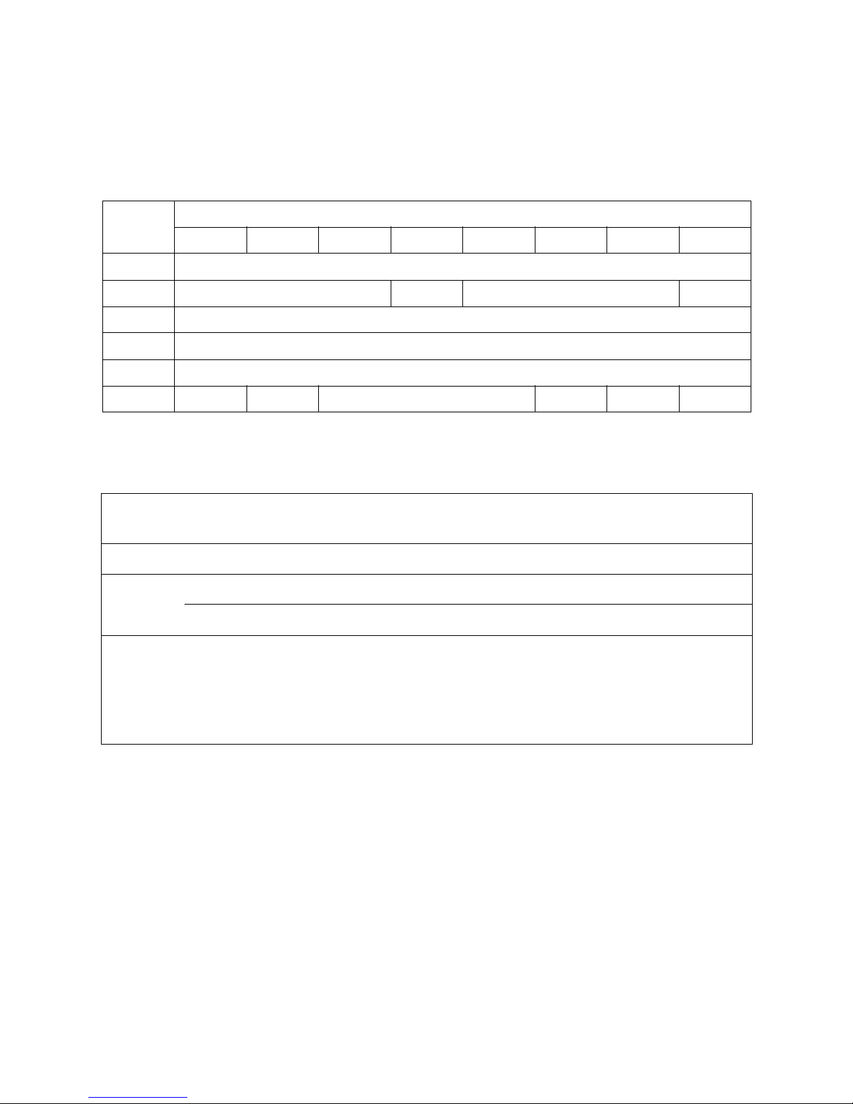
Table 2-1: Initialize Element Status Command–07h
Byte
Bits
76543210
00 Operation Code (07h)
01 Obsolete
a
a. These bits are ignored.
Reserved
02 Reserved
03 Reserved
04 Reserved
05 Control
b
b. Must be zero.
Page 15

15
3 Initialize Element Status With
Range—E7h or 37h
Command Description
INITIALIZE ELEMENT STATUS WITH RANGE is a vendor-specific command for other vendors’ tape
libraries. It is included in the T-Series and 50-Series libraries’ command set to support
the library’s emulation of other libraries.
When the library receives this command, it performs as though it had received the
INITIALIZE ELEMENT STATUS (07h) command, ignoring any additional parameters supplied with
this command. See Chapter 2. Initialize Element Status—07h for more information on
the command.
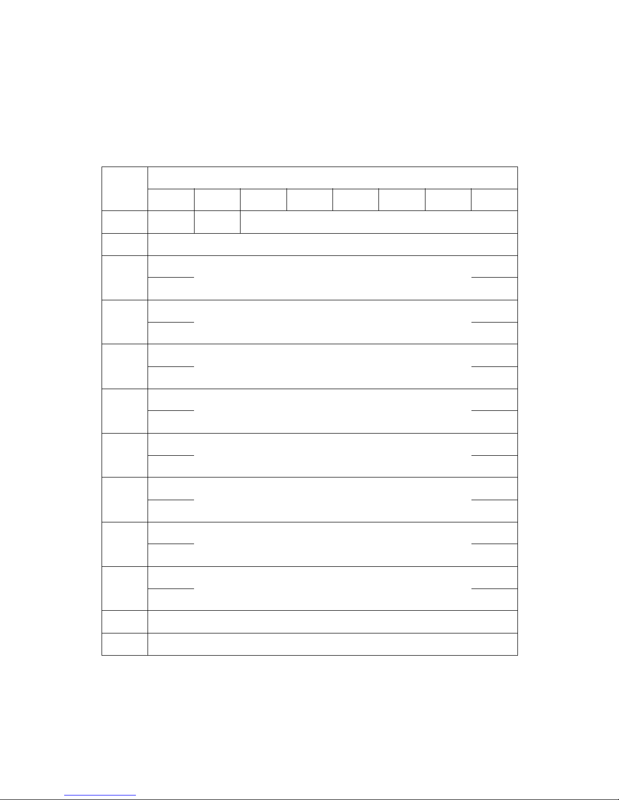
Table 3-1: Initialize Element Status With Range Command–E7h
Byte
Bits
76543210
00 Operation Code (E7h or 37h)
01 Obsolete
a
a. These bits are ignored.
Reserved Fast
a
Range
a
02 (MSB)
Element Address
a
03 (LSB)
04 Reserved
05 Reserved
06 (MSB)
Number of Elements
a
07 (LSB)
08 Reserved
09 Control
b
b. Must be zero.
Page 16

16
4Inquiry—12h
Command Description
The INQUIRY command instructs the library to send information regarding its parameters
to the initiator. The table below shows the CDB for the INQUIRY command.
Table 4-1: Inquiry Command–12h
Byte
Bits
76543210
00 Operation Code (12h)
01 Obsolete
a
a. These bits are ignored.
Reserved CMDDT EVPD
02 Page Code
03 Reserved
04 Allocation Length
05 00 Reserved 000
Table 4-2: Inquiry Command Field Values
Field Name
Values
Allowed Meaning
Logical Unit
Number
0h This bit is ignored.
CMDDT 0 Command support data.
Enable Vital
Product Data
0 Requests the library to return only the standard Inquiry Data page. (The Page Code must be 0.)
1 Requests that the library return the Page Code page.
Page Code
00h When the EVPD bit is 1, this returns a list of supported pages (00h, 80h, 83h).
80h When the EVPD bit is 1, this returns the library’s serial number page.
83h When the EVPD bit is 1, this returns the library’s identification page.
Allocation
Length
00-FFh
Specifies the number of bytes the initiator allocates for data returned from the inquiry
command. Zero indicates no inquiry data is to be transferred; this condition is not considered an
error. The library terminates the data in phase when it transfers either the number of bytes
specified by the allocation length field or all of the available inquiry data, whichever is less. The
data length for the standard inquiry data returned by the library is 38h (56 bytes).
Page 17

Chapter 4. Inquiry—12h
17
Command Response
Table 4-3: Standard Inquiry Data Format
Byte
Bits
76543210
00 Peripheral Qualifier Peripheral Device Type
01 RMB Reserved
02 Version = 05h
03 Obsolete Obsolete NormACA HiSup Response Data Format
04 Additional Length (n-4)
05 SCCS ACC ALUA 3PC Reserved
06 BQue EncServ VS MultiP MChngr Obsolete Obsolete Addr16
07 RelAdr Obsolete WBus16 Sync Linked Obsolete CmdQue VS
08 (MSB)
Vendor Identification
15 (LSB)
16 (MSB)
Product Identification
31 (LSB)
32 (MSB)
Product Revision Level
35 (LSB)
36 (MSB)
Vendor-Specific
55 (LSB)
56 Reserved Clocking QAS IUS
57 Reserved
Page 18

Chapter 4. Inquiry—12h
18
Table 4-4: Standard Inquiry Data Field Values
Field Name
Value
Returned Meaning
Peripheral
Qualifier
000b The library is a single LUN device. This value is returned only if the LUN sent is 0h.
011b If the LUN in the ID message is not 0h, this indicates that this LUN is not supported.
Peripheral
Device Type
08h Identifies the library as a media changer device, returned only if the LUN sent is 0h.
1Fh Returned if the LUN in the ID message is not 0h; it indicates that the LUN is an unknown type.
RMB 1 Indicates media is removable from the library.
ISO 00b
The library supports the current ANSI version of the SPC-3 Standard. ECMA 000b
ANSI 010b
NormACA 0 The library does not support setting the Normal ACA Supported bit to 1.
HiSup 0 The library does not use the hierarchical addressing model to assign LUNs to logical units.
Response
Data Format
2h
INQUIRY data returned by T-Series and 50-Series libraries conforms to the format defined in
the SPC-3 Standard.
Additional
Length
n-4
There are n-4 bytes of data following this byte, where n is the last byte returned.
Libraries exported through QIPs return Bytes 0-35 (n=35).
Libraries exported through direct-attached drives return Bytes 0-57 (n=57), with the tape
drive responsible for Bytes 36-57. Refer to the tape drive manufacturer’s SCSI specification for
a definition of those bytes and the bits for clocking, QAS, and IUS in Byte 56.
SCCS 0 The library does not contain an embedded storage array controller component.
ACC 0 No access controls coordinator may be addressed through this logical unit.
ALUA 0
The SCSI target device does not support asymmetric logical unit access or vendor-specific
asymmetric access. Neither REPORT TARGET GROUPS or SET TARGET GROUPS is supported.
3PC
1 Indicates that device support for third-party or EXTENDED COPY commands is enabled.
0 A 3PC bit of zero indicates that device support for such commands is disabled.
BQue 0 The library does not support tagged tasks (command queuing) for this logical unit.
EncServ 0 The library does not contain an embedded enclosure services component.
VS 0 The library does not support vendor-specific data.
MultiP
1 The library’s port addressing is overlapped.
0 The library‘s port addressing is split.
MChngr 0 The library is not embedded within or attached to a medium transport element.
Page 19

Chapter 4. Inquiry—12h
19
Addr16
0 The library does not support wide SCSI addressing.
1 Direct-attach drives support wide SCSI addressing.
RelAdr 0 The library does not support relative addressing.
WBus16
0 The library does not support 16-bit wide transfers.
1 Direct-attach drives support 16-bit wide transfers.
Sync
0 The library does not support synchronous data transfer.
1 Direct-attach drives support synchronous data transfer.
Linked 0 The library does not support command linking.
CmdQue 0 The library does not support tagged command queuing.
Vendor
Identification
Spectra
a
These bytes are the ASCII representation of SPECTRA (uppercase) followed by a space (20h).
b
Product
Identification
PYTHON
a
This is the product identification returned by all T-Series and 50-Series tape libraries.
b
Product
Revision
Variable
a
These bytes are the ASCII representation of the current product revision level, with space
(20h) characters to fill four bytes (for example, 2.00).
Clocking
0 The device server only supports single timing.
00b
c
Set if the host interface speed has been set to limit transfers to 80 MB/s.
11b
c
Set if the host interface speed has not been set to limit transfers to 80 MB/s.
QAS 0 The device server does not support quick arbitration and selection.
IUS 0 The device server does not support information unit transfers.
a. The Vendor Identification, Product Identification, and Product Revision Level data fields all return ASCII-format data. Unused bytes are filled with
space characters (20h) left-justified.
b. The Vendor Identification and Product Identification data fields may be changed to support other emulations.
c. Supported only on direct-attach drives that support Ultra160 SCSI.
Table 4-4: Standard Inquiry Data Field Values
Field Name
Value
Returned Meaning
Page 20

Chapter 4. Inquiry—12h
20
In the INQUIRY command, when the EVPD is 1 and the Page Code is 00h, the Command
Response is a Supported Pages page.
Table 4-5: Supported Pages Page
Byte
Bits
76543210
00 Peripheral Qualifier Peripheral Device Type
01 Page Code (00h)
02 Reserved (00h)
03 Page Length (03h)
04 Supported Pages Page (00h)
05 Serial Number Page (80h)
06 Device Identification Page (83h)
Table 4-6: Serial Number Page
Byte
Bits
76543210
00 Peripheral Qualifier Peripheral Device Type
01 Page Code
02 Reserved
03 Page Length
04-23 Serial Number of Library(ASCII)
Page 21

Chapter 4. Inquiry—12h
21
Table 4-7: Serial Number Page Field Values
Field Name
Value
Returned Meaning
Peripheral Qualifier 000b
The library is a single LUN device. This value is returned only if the LUN sent in the
INQUIRY command is 0h.
Peripheral Device
Typ e
08h
Identifies the library as a media changer device. This value is returned only if the
LUN sent in the INQUIRY command is 0h.
1Fh
This value is returned if the LUN sent in the INQUIRY command is not 0h. It
indicates that the LUN is an unknown type.
Page Code 80h Serial number page.
Page Length Varies
a
a. The serial number can be up to 20 characters in length.
Length of serial number.
Serial Number Varies
a
ASCII representation of library serial number.
Page 22

Chapter 4. Inquiry—12h
22
Table 4-8: Library Identification Page
Byte
Bits
76543210
00 Peripheral Qualifier Peripheral Device Type (08h)
01 Page Code
02 Reserved (00h)
03
Page Length
(32h for QIP-attached libraries)
(26h for direct-attached drives)
04 Reserved Code Set (02h)
05 Reserved Identifier Type (01h)
06 Reserved (00h)
07 Identifier Length (22h)
08 - 15 Vendor ID (SPECTRA)
16 - 31 Product ID (PYTHON)
32 - 41 Serial Number of the Library
42
Code Set
a
(Identifier contains binary data = 01h)
43
Identifier Type
a
(FC_PH 64-bit Name_Identifier == WWN = 03h)
44 Reserved
a
45
Identifier Length
a
(beyond header = 08h)
46 - 53 World Wide Name
a
a. Applicable only to Fibre Channel, Gigabit Ethernet, NDMP, and iSCSI libraries. These will not be reported on SCSI interface systems.
Page 23

Chapter 4. Inquiry—12h
23
Table 4-9: Serial Number Page Field Values
Field Name
Value
Returned Meaning
Peripheral Qualifier 000b
The library is a single LUN device. This value is returned only if the LUN
sent in the INQUIRY command is 0h.
Peripheral Device Type
08h
Identifies the library as a media changer device. This value is returned
only if the LUN sent in the INQUIRY command is 0h.
1Fh
This value is returned if the LUN sent in the INQUIRY command is not 0h.
It indicates that the LUN is an unknown type.
Page Code 83h Device Identification Page.
Page Length
32h Libraries exported through QIPs return 50 (32h) bytes.
26h Libraries exported through direct-attached drives return 38 (26h) bytes.
Code Set 02h The Identifier field contains ASCII graphic codes.
Identifier Type 01h The Identifier field is associated with the post that received the request.
Identifier Length 22h T-Series and 50-Series libraries return 34 (22h) bytes.
Serial Number Variable
a
ASCII representation of library serial number.
Vendor Identification SPECTRA
b
These bytes are the ASCII representation of SPECTRA (uppercase)
followed by a space (20h).
Product Identification PYTHON
This is the product identification returned by all T-Series and 50-Series
libraries.
World Wide Name
c
Variable Actual WWN of QIP (not ASCII represented).
a. The serial number can vary between two and seven digits in length. All T-Series and 50-Series libraries currently report 04.
b. The vendor identification, product identification, product revision level, and patch level data fields all return ASCII-format data. Unused bytes are
filled with space characters (20h).
c. Fibre Channel interface libraries and drives only.
Page 24

24
5Mode Select—15h
Command Description
The MODE SELECT command allows the initiator to change device parameters of the library.
An initiator uses these parameters to configure the library after power-up or a bus
device reset message. The library parameters that can be set with MODE SELECT are as
follows:
• Element Address Assignments Page (1Dh) has these changeable bits:
• Bytes 2,3
• Bytes 6,7
• Bytes 10,11
• Bytes 14,15
• Transport Geometry Page (1Eh) has no changeable bits
• Device Capabilities Page (1Fh) has no changeable bits
If requested, by setting the SP (save pages) bit in the command descriptor, the library
saves applicable mode parameters to nonvolatile RAM and automatically reloads them
when it initializes, following a reset or power-up.
Any changed parameters apply to all initiators in a multi-initiator environment. If mode
parameters are changed, the library generates a UNIT ATTENTION to all initiators, except the
one that issued the MODE SELECT command, with sense information to indicate that mode
parameters have changed.
Note: Before issuing any MODE SELECT command, issue a MODE SENSE
command with the Page Code field set to 3Fh, so the T-Series or
50-Series library returns all mode pages, and the Page Control field
set to 01h, so the library indicates which fields are changeable.
Page 25
Chapter 5. Mode Select—15h
25
To change parameter values, send a MODE SELECT command, followed by a mode
parameter list in the Data Out phase. Table 5-1 shows the CDB for the MODE SELECT
command.
Table 5-1: Mode Select Command–15h
Byte
Bits
76543210
00 Operation Code (15h)
01 Obsolete
a
a. These bits are ignored.
PF Reserved SP
02 Reserved
03 Reserved
04 Parameter List Length
05 0 0 Reserved 0 0 0
Table 5-2: Mode Select Command Field Values
Field Name
Values
Allowed Meaning
PF 1 The library supports the page format defined by the SPC-3 Standard.
SP
(Save Pages)
0 Mode pages are not saved. Mode parameter changes requested are still made.
1 All mode pages are saved, whether they are changed in this command or not.
Parameter
List Length
00-FFh
The value of this byte represents the length of the entire parameter list, including the
parameter list header. When the value of the parameter list length is 00h, no parameter list is
transferred from the initiator. This is not considered an error. You might send a MODE SELECT
command with no parameter list and the SP bit set to 1, for example, to force the T-Series or
50-Series library to save its current mode page settings without changing them.
Page 26

Chapter 5. Mode Select—15h
26
Mode Parameter Lists
Following the command block, in the data out phase, the initiator sends a parameter
list containing the new parameter values of the library. This parameter list has the
same format as the data the library returns to a MODE SENSE command. The parameter list
is accompanied by the parameter list header (See Table 6-3 on page 29). See also the
MODE SENSE chapter for detailed descriptions of all mode parameters.
The following restrictions apply when reassigning element addresses:
• Element addresses must not overlap other element groups.
• Element groups (i.e., cartridge slots, tape picker, drives) must be assigned
contiguous addresses.
• Element addresses must be between 0 and 65,535 (0x FFFF).
Page 27

27
6Mode Sense—1Ah
Command Description
The MODE SENSE command asks the library to report its operating mode parameters to the
initiator. The parameters are returned in mode pages. The library supports the
following pages:
• Element address assignments—1Dh
• Tape picker capabilities (transport geometry parameters)—1Eh
• Device capabilities, such as where media can be moved or stored—1Fh
These pages are described in detail under Command Response on page 29. The
initiator can change some of these parameters using the MODE SELECT (15h) command.
The SPC-3 Standard provides both a 6-byte and a 10-byte MODE SENSE command. The
library uses the 6-byte command. The table below shows the CDB for the MODE SENSE
command.
Table 6-1: Mode Sense Command–1Ah
Byte
Bits
76543210
00 Operation Code (1Ah)
01 Obsolete
a
a. These bits are ignored.
Reserved DBD Reserved
02 Page Control Page Code
03 Reserved
04 Allocation Length
05 00 Reserved 000
Page 28

Chapter 6. Mode Sense—1Ah
28
Table 6-2: Mode Sense Command Field Values
Field Name Values Allowed Meaning
DBD (Disable Block
Descriptors)
0 or 1
The library does not return block descriptors even if requested to do so. This is
not an error condition. It simply returns a block descriptor length of 0.
Page Control
0h Requests current mode parameter values.
1h
Requests changeable parameters. The requested mode pages are returned,
but rather than parameter values, bits are set to 1 if changeable or 0 if not.
2h Requests default values.
3h
Requests saved values. If a page has not been saved, default values are
returned.
Page Code
3Fh Requests the library return all available mode pages.
1Dh Requests element address assignment page only.
1Eh Requests transport geometry parameters page only.
1Fh Requests device capabilities page only.
Allocation Length 00-FFh
Specifies the number of bytes the initiator allocates for data returned. Zero
indicates no mode data is to be transferred; this condition is not considered
an error. The library terminates the data in phase when it transfers either the
number of bytes specified by the allocation length field or all of the available
mode parameter data, whichever is less. The data length for all mode
parameter pages returned by the library is 48 bytes (30h).
Page 29

Chapter 6. Mode Sense—1Ah
29
Command Response
If all mode pages are requested, the library returns 48 bytes of mode sense data to the
initiator, structured as follows:
• 4 bytes of parameter list header data
• 20 bytes of element address assignments
• 4 bytes of transport geometry descriptors
• 20 bytes of device capabilities parameters
Each of these items is described in the tables that follow. Note that when a specific
page is requested, the library returns only the header data and the specific page.
The Mode Data Length (byte 00) indicates the number of bytes of parameter information
available to the initiator, not including the Mode Data Length byte itself. For example, if
all mode pages are requested, this value is 43 (2Bh), one byte less than the total mode
parameter length available.
Table 6-3: Parameter List Header Format
Byte
Bits
76543210
00 Mode Data Length
01 - 03 Reserved for other device types
Page 30
Chapter 6. Mode Sense—1Ah
30
Element Address Assignments
For the default values of the element addresses, see Chapter 9. Read Element Status—
B8h.
The value of 1 for PS (“page savable,” byte 00, bit 7) indicates that the page can be saved to
nonvolatile RAM. This is done by setting the SP field in the MODE SELECT command. See
Chapter 5. Mode Select—15h for details.
Table 6-4: Element Address Assignments Page–1Dh
Byte
Bits
76543210
00 PS–1 Reserved Page Code–1Dh
01 Parameter List Length (following this byte)(12h)
02 (MSB)
Medium Transport Element Address (default=0001h)
03 (LSB)
04 (MSB)
Number of Medium Transport Elements
01h for all T-Series and 50-Series libraries
05 (LSB)
06 (MSB)
First Storage Element Address(default=1000h)
07 (LSB)
08 (MSB)
Number of Storage Elements
(depends on partition size)
09 (LSB)
10 (MSB)
First Import/Export Element Address
(default=0010h)
11 (LSB)
12 (MSB)
Number of Import/Export Elements
(depends on configuration)
13
14 (MSB)
First Data Transfer Element Address
(default=0100h)
15 (LSB)
16 (MSB)
Number of Data Transfer Elements
(depends on partition size)
17 (LSB)
18 Reserved
19 Reserved
Page 31

Chapter 6. Mode Sense—1Ah
31
Transport Geometry Parameters
The transport geometry parameter page identifies that the tape picker does not rotate
media.
Note: These values cannot be modified with the MODE SELECT command.
The Rotate (byte 02, bit 0) field identifies the ability of the picker to handle two-sided media.
The library uses only one-sided media, so the value returned for this bit is 0.
Table 6-5: Transport Geometry Parameter Page–1Eh
Byte
Bits
76 543210
00 PS–0 Reserved Page Code–1Eh
01 Parameter Length to Follow this Byte–02h
02
Reserved
Rotate
0
03 Member Number in Transport Element Set–00h
Page 32

Chapter 6. Mode Sense—1Ah
32
Device Capabilities
The device capabilities mode page is described in the table below.
Table 6-6: Device Capabilities Fields Format–1Fh
Bytes
Bits
76543210
00 PS–0 Reserved Page Code–1Fh
01 Parameter Length–12h
02 Reserved (0)
StorDT
1
StorI/E
1
StorST
1
StorMT
0
03 Reserved (00)
04 Reserved (0)
MT->DT
1
MT->IE
1
MT->ST1MT->MT
0
05 Reserved (0)
ST->DT
1
ST->IE
1
ST->ST
1
ST->MT
0
06 Reserved (0)
IE->DT
1
IE->IE
1
IE->ST
1
IE->MT
0
07 Reserved (0)
DT->DT
1
DT->IE
1
DT->ST
1
DT->MT
0
08 - 11 Reserved
12
Reserved (0)
MT<>DT0MT<>IE0MT<>ST0MT<>MT
0
13
ST<>DT
0
ST<>IE
0
ST<>ST0ST<>MT
0
14
IE<>DT
0
IE<>IE
0
IE<>MT0IE<>MT
0
15
DT<>DT0DT<>IE
0
DT<>ST0DT<>MT
0
16 - 19 Reserved
Page 33

Chapter 6. Mode Sense—1Ah
33
In Table 6-6: Device Capabilities Fields Format–1Fh on page 32, the following
abbreviations and definitions apply:
DT: Data transfer element (tape drive)
IE: Import/export element (TAP)
ST: Storage element (magazine slot)
MT: Medium transport element (tape picker)
Stor: A value of 1 in a StorXX bit indicates media can be stored at elements of type XX.
A value of 0 indicates that it cannot.
->: A value of 1 in a XX -> YY bit indicates that media can be moved from elements of
type XX to elements of type YY.
<>: A 1 in a XX<>YY bit indicates that media can be exchanged between elements of
types XX and YY. All of these values are 0 because the library does not support media
exchanges.
For example, the 1 in the StorDT bit indicates that media can be stored at data transfer
element addresses (tape drives). The 0 in the MT->MT bit indicates that media cannot
be moved from one medium transport element to another medium transport element;
this is because there is only one medium transport element.
Page 34

34
7 Move Medium—A5h
Command Description
The MOVE MEDIUM command asks the library to move media from one element location to
another. The locations are identified by their element addresses.
The MODE SENSE data contains a matrix with the valid element source-destination
combinations for the MOVE MEDIUM command, as described in Table 6-6: Device
Capabilities Fields Format–1Fh on page 32. Send a READ ELEMENT STATUS command to the
library to find out current element addresses and which elements contain media. The
table below shows the CDB for the MOVE MEDIUM command.
Table 7-1: Move Medium Command–A5h
Byte
Bits
7 6543210
00 Operation Code (A5h)
01 Obsolete
a
a. These bits are ignored.
Reserved
02 (MSB)
Transport Medium Address
03 (LSB)
04 (MSB)
Source Address
05 (LSB)
06 (MSB)
Destination Address
b
b. There is no movement allowed to the robotic picker (medium transport element).
07 (LSB)
08
Reserved
09
10 Reserved Invert
11 0 0 Reserved 0 0 0
Page 35

Chapter 7. Move Medium—A5h
35
Table 7-2: Move Medium Command Field Values
Field Name
Values
Allowed Meaning
Transport Element Address Varies
a
The element address of the picker (the default is 0001h).
This value must match the value from MODE SENSE or be 0000h.
Source Address Varies
a
The current element address of the slot or drive where the cartridge is.
Destination Address
b
Var ies
a
The element address of the slot or drive where the cartridge will be moved.
Invert 0 T-Series and 50-Series libraries do not support the invert function.
a. Permitted values for the Transport Element, Source, and Destination Addresses can be changed with the MODE SELECT command. Use the MODE
SENSE command to determine element address settings. For more information, see Chapter 5. Mode Select—15h and Chapter 6. Mode Sense—1Ah.
Default element addresses are listed in Chapter 9. Read Element Status—B8h.
b. There is no movement allowed to the robotic picker (medium transport element).
Page 36

36
8 Prevent/Allow Medium
Removal—1Eh
Command Description
The PREVENT/ALLOW MEDIUM REMOVAL command determines whether the library permits the
removal of data cartridges through the import/export ports.
Table 8-1: Prevent/Allow Medium Removal Command–1Eh
Byte
Bits
76543210
00 Operation Code (1Eh)
01 Obsolete
a
a. These bits are ignored.
Reserved
02 Reserved
03 Reserved
04 Reserved Prevent
05 00 Reserved 000
Table 8-2: Prevent/Allow Medium Removal Command Values
Field Name Values Allowed Meaning
Prevent 0 Media removal allowed.
1 Media removal prevented.
Page 37

37
9 Read Element Status—B8h
Command Description
The READ ELEMENT STATUS command requests that the library return the status of the
selected elements in the library. An element’s status includes its element address,
element type, whether it contains media, and whether it is in an abnormal state. If the
VolTag command option is set, media bar code information is also returned. If an
element is in an abnormal state, indicated by the Except bit in returned data, the
library also supplies sense information to indicate the nature of the abnormal state.
Table 9-1 shows the CDB for the READ ELEMENT STATUS command.
Table 9-1: Read Element Status Command–B8h
Byte
Bits
76543210
00 Operation Code (B8h)
01 Obsolete
a
a. These bits are ignored.
VolTag Element Type Code
02 (MSB)
Starting Element Address
03 (LSB)
04 (MSB)
Number of Elements
05 (LSB)
06 Reserved CurData DVCID
07 (MSB)
Allocation Length
08
09 (LSB)
10 Reserved
11 00 Reserved 0 00
Page 38

Chapter 9. Read Element Status—B8h
38
Table 9-2: Read Element Status Command Values
Field Name Values Allowed Meaning
VolTag
1
Set to 1 to have the library return bar code label (volume tag) information.
0
Element Type
Code
0h Return status for all element types.
1h Return status only for the medium transport element.
2h Return status only for storage elements.
3h Return status only for import/export elements.
4h Return status only for data transfer elements.
Starting Element
Address
0 to maximum
number for type.
The library only reports the status of elements at or above this Starting
Element Address, and of the type specified by the Element Type Code.
CurData
1
This bit is ignored since inventory is always kept updated.
0
DVCID
0 The library will not return device identifiers.
1
The library will return device identifiers, if available (i.e., only the Data Transfer
Element Descriptor provides the device identifier information).
Number of
Elements
0 - maximum
number for
elements
a
The library sends descriptors for elements, specified by the Element Type Code
and Starting Element Address options, until it sends the lesser of:
- All available element descriptors.
- The number of element descriptors specified by Number of Elements
as many complete element descriptors as it can without exceeding the
number of bytes specified by Allocation Length.
Allocation Length Any
a
a. Setting these fields to 0 does not constitute an error.
Page 39

Chapter 9. Read Element Status—B8h
39
Command Response
In the data in phase, the library sends element status data in the format defined by the
SPC-3 Standard. This data consists of the following:
• Element Status Data Header (8 bytes), as shown in Table 9-3 below.
• Element Status Pages, one page for each Element Type reported, each with the
following format:
• Element Status Page Header (8 bytes), shown in Table 9-5 on page 40.
• Element Descriptors, one for each element reported. Each Element Type has a
different format, and the data block size varies by element type. Tables 10-6
through 10-13 illustrate the Element Descriptors for each element type.
Table 9-3: Element Status Data Header Format
Byte
Bits
76543210
00 (MSB)
FIrst Element Address Reported
01 (LSB)
02 (MSB)
Number of Elements Reported
03 (LSB)
04 Reserved
05 (MSB)
Byte Count of All Element Status Pages
(does not include this header)
06
07 (LSB)
Page 40

Chapter 9. Read Element Status—B8h
40
The Element Status Data Header is followed immediately by Element Status Pages for
each element type reported. Each Element Status Page consists of a header followed by
Element Descriptors for each element reported.
Table 9-4: Element Status Data Header Field Values
Field Name Value Returned Meaning
First Element Address
Reported
Varies
This value represents the first element address matching the command. This
is true regardless of restrictions of Allocation Length.
Number of Elements
Reported
Varies
This value represents the number of elements of the entire Response Data.
This is true regardless of restrictions of Allocation Length.
Byte Count of All
Element Status Pages
Varies
This value represents the byte count of the entire Response Data. This is true
regardless of restrictions of Allocation Length.
Table 9-5: Element Status Page Header Format
Byte
Bits
7 6 543210
00 Element Type Code
01 PVolTag AVolTag Reserved
02 (MSB)
Element Descriptor Length
03 (LSB)
04 Reserved
05 (MSB)
Byte Count of Available Descriptor Data
(this Element Status Page only, n-7)
06
07 (LSB)
08 - n
Element Descriptor(s) - length depends on element type.
See Tables 9-7 through 9-14 for details.
Page 41

Chapter 9. Read Element Status—B8h
41
Element Descriptors
Following each Element Status Page header are one or more Element Descriptors, one
for each element reported of the type identified by the Element Type Code in the
header. Each Element Descriptor includes the Element Address and Element Status.
The four types of Element Status Pages are:
• Medium Transport Element Descriptor Page
• See Table 9-7 on page 42 and Table 9-8 on page 43
• Storage Element Descriptor Page
• See Table 9-9 on page 44 and Table 9-10 on page 45
• Data Transfer Element Descriptor Page
• See Table 9-11 on page 46 and Table 9-12 on page 47
• Import/Export Element Descriptor Page
• See Table 9-14 on page 50 and Table 9-14 on page 50
Table 9-6: Element Status Page Header Field Values
Field Name
Value
Returned Meaning
Element Type
Code
01h Descriptors in this page are for the medium transport element.
02h Descriptors in this page are for storage elements.
03h Descriptors in this page are for import/export elements.
04h Descriptors in this page are for data transfer elements.
PVolTag
0 Bar code information (primary volume tag) is omitted from the descriptors.
1 Bar code information (primary volume tag) is included in the descriptors.
AVol Tag 0
Alternate volume tag information is not included in the descriptors. T-Series and 50-Series
libraries do not support alternate volume tags.
Byte Count of
Available
Descriptor Data
Varies This value is the Descriptor Length multiplied by the number of descriptors returned.
Element
Descriptor
Length
Varies
This value represents the size of each element descriptor.
This value depends on which element type is being reported and whether the primary
volume tag is included (indicated by the PVolTag bit).
See the tables below for details on Element Descriptor blocks for each element type.
Page 42

Chapter 9. Read Element Status—B8h
42
Medium Transport Element
There is only one medium transport element in T-Series and 50-Series libraries. Below
is the Element Descriptor.
Table 9-7: Medium Transport Element Descriptor (Tape Picker)
Byte
Bits
76543210
00 (MSB)
Element Address
(default = 0001h)
01 (LSB)
02 Reserved Except Reserved Full
03 Reserved
04 Additional Sense Code
05 Additional Sense Code Qualifier
06 -
Reserved
08
09 SValid Invert–0 Reserved
10 - 11
(MSB)
Source Storage Element Address
(LSB)
12 - 47
(MSB)
Primary Volume Tag Information
(Field omitted if PVolTag=0)
(LSB)
48 - 51
Reserved
(Field moved to [12-15] if Primary Volume Tag Information field is omitted.)
Page 43

Chapter 9. Read Element Status—B8h
43
Table 9-8: Medium Transport Element Descriptor Fields
Field Name Value Returned Meaning
Element Address Varies
The address used to identify the medium transport element (robotic tape
picker).
Each element in the library must have a unique address. Element addresses are
used by almost all medium changer device SCSI commands to identify locations
applicable to the particular command. Each element has a factory-set default
address, but the addresses can be reassigned with the MODE SELECT command.
Except
0 An Except bit value of 1 indicates that the element is in some sort of abnormal
state. More information on the nature of the exception is available in the ASC
and ASCQ fields, described below.
1
Full
1 A value of 1 indicates that the specified element contains media.
0 A value of 0 indicates that the element does not contain media.
Additional Sense
Code (ASC)
Var ies
The ASC and ASCQ together may provide more information about the condition
that caused the Except bit to be set to 1.
Their meaning here is the same as the ASC and ASCQ returned to the REQUEST
SENSE command. For a listing of the meanings of all ASC-ASCQ combinations,
see Chapter 15. Error Reporting.
Additional Sense
Code Qualifier
(ASCQ)
Var ies
SValid
(Source Valid)
1 Indicates that the value in the Source Storage Element Address field is valid.
0 Indicates that the value in the Source Storage Element Address field is not valid.
Invert 0
This bit is always 0 because T-Series and 50-Series libraries do not invert
cartridges.
Source Storage
Element Address
Varies Indicates the source address of where the media was previously located.
Primary Volume
Tag Information
Var iesa
If the PVolTag bit in the data header is 1, this field contains the bar code (volume
tag) information for the cartridge occupying this element.
If the PVolTag bit is 0, this field is omitted entirely. There is rarely a bar code
associated with this element type.
a. The library only supports the first 10 characters of a bar code. If the bar code is larger than 10 characters, only the first 10 characters will be reported.
Page 44

Chapter 9. Read Element Status—B8h
44
Storage Elements
The slots in the T-Series and 50-Series libraries’ data cartridge magazines are the
storage elements.
Table 9-9: Storage Element Descriptor (Magazine Slots)
Byte
Bits
76543210
00 (MSB)
Element Address
(default = 1000h)
01 (LSB)
02 Reserved Access Except Reserved Full
03 Reserved
04 Additional Sense Code
05 Additional Sense Code Qualifier
06 - 08 Reserved
09 SValid Invert–0 Reserved
10 (MSB)
Source Storage Element Address
11 (LSB)
12 - 47
(MSB)
Primary Volume Tag Information
(Field omitted if PVolTag=0)
(LSB)
48 -51 Reserved (Field moved to [12-15] if Primary Volume Tag Information field is omitted.)
Page 45

Chapter 9. Read Element Status—B8h
45
Table 9-10: Storage Element Fields
Field Name
Value
Returned Meaning
Element
Address
Varies
a
The address used to identify the storage elements (cartridge slots).
Each element in the library must have a unique address. Element addresses are used by
almost all medium changer device type-specific SCSI commands to identify locations
applicable to the particular command. Each element has a factory-set default address, but
the addresses can be reassigned with the MODE SELECT command.
Access
1 A value of 1 indicates that the specified element is accessible by the picker.
0 A value of 0 indicates that the specified element is not accessible by the picker.
Except
1
An Except bit value of 1 indicates that the element is in some sort of abnormal state. More
information on the nature of the exception is available in the Additional Sense Code and
Additional Sense Code Qualifier fields, described below.
0
An Except bit value of 0 indicates No Problem. If ASC or ASCQ values exist, they are not
valid.
Full
1 A value of 1 indicates that the specified element contains media.
0 A value of 0 indicates that the specified element does not contain media.
Additional
Sense Code
(ASC)
Varies
b
The ASC and ASCQ together may provide more information about the condition which
caused the Except bit to be set to 1. Their meaning here is the same as the ASC and ASCQ
returned to the REQUEST SENSE command. For a listing of the meanings of all ASC-ASCQ
combinations, see Chapter 15. Error Reporting.
Additional
Sense Code
Qualifier (ASCQ)
Varies
b
SValid
(Source Valid)
1 Indicates that the value in the Source Storage Element Address field is valid.
0 Indicates that the value in the Source Storage Element Address field is not valid.
Invert 0 This bit is always 0 because T-Series and 50-Series libraries do not invert cartridges.
Source Storage
Element
Address
Varies
a
Indicates the source address of where the media was previously located.
Primary Volume
Tag Information
Varies
c
If the PVolTag bit in the data header is 1, this field contains the bar code (volume tag)
information for the cartridge occupying this element.
If the PVolTag bit is 0, this field is omitted entirely.
a. The Range of Values is supported by the MODE SELECT command.
b. Se e Chapter 15. Error Reporting for supported ASC and ASCQ values.
c. The bar code of the media element in ASCII format (see Table 9-14 on page 50 for maximum character length).
Page 46

Chapter 9. Read Element Status—B8h
46
Data Transfer Elements
The data transfer elements are the tape drives.
Table 9-11: Data Transfer Element Descriptor (Tape Drive)
Byte
Bits
76543210
00 (MSB)
Element Address
(default = 0100h)
01 (LSB)
02 Reserved Access Except Reserved Full
03 Reserved
04 Additional Sense Code
05 Additional Sense Code Qualifier
06 Obsolete Reserved Obsolete Obsolete Reserved Obsolete
07 Obsolete
08 Reserved
09 SValid Invert Reserved
10 (MSB)
Source Storage Element Address
11 (LSB)
12 - 47
(MSB)
Primary Volume Tag Information
(Field omitted if PVolTag=0)
a
a. Bytes 48-61 will be moved up if the PVolTag bit is zero. Byte 48 would become Byte 12, Byte 49 would become Byte 13, and so forth.
(LSB)
48 Reserved Code Set
49 Reserved Identifier Type
50 Reserved
51 Identifier Length
52 - 61
Identifier
(Field omitted if DVCID=0)
Page 47

Chapter 9. Read Element Status—B8h
47
Table 9-12: Data Transfer Element Descriptor Fields
Field Name Value Returned Meaning
Element
Address
Varies
a
The address used to identify the data transfer element (drive).
Each element in the library must have a unique address. Element addresses are
used by almost all medium changer device type-specific SCSI commands to
identify locations applicable to the particular command. Each element has a
factory-set default address, but the addresses can be reassigned with the MODE
SELECT command.
Access
1 If accessible by the robotic tape picker.
0 If not accessible by the robotic tape picker.
Except
1
Indicates that the element is in some sort of abnormal state. More information on
the nature of the exception is available in the Additional Sense Code and
Additional Sense Code Qualifier fields, described below.
0 Indicates No Problem. If ASC or ASCQ values exist, they are not valid.
Full
1 Indicates that the specified element contains media.
0 Indicates that the element does not contain media.
ASC
Varies
b
The ASC and ASCQ together may provide more information about the condition
which caused the Except bit to be set to 1.
Their meaning here is the same as the ASC and ASCQ returned to the REQUEST
SENSE command. For a listing of the meanings of all ASC-ASCQ combinations, see
Chapter 15. Error Reporting.
ASCQ
CodeSet
When DVCID = 0 ...
- Code Set = 0
- Identifier = 0
The Code Set, the Identifier Type and Length, and the Identifier are not valid.
When DVCID = 1 ...
- Code Set = 2
- Identifier = 1
The Code Set, the Identifier Type and Length, and the Identifier are valid.
Identifier Type 1 The first eight bytes are a vendor ID. The identifier is unique.
Identifier
Length
c
0Ah
00h
The identifiers are 10 bytes in length.
Identifier Varies
c
ASCII representation of the drive serial number.
SValid
(Source Valid)
1 Indicates that the value in the Source Storage Element Address field is valid.
0 Indicates that the value in the Source Storage Element Address field is not valid.
Invert 0 T-Series and 50-Series libraries do not invert cartridges.
Page 48

Chapter 9. Read Element Status—B8h
48
Source Storage
Element
Address
Varies
a
This field is the cartridge’s last storage element address.
Primary Volume
Tag Information
Varies d
If the PVolTag bit in the data header is 1, this field (in ASCII format) contains the
bar code (volume tag) information for the cartridge occupying this element.
If the PVolTag bit is 0, this field is omitted entirely.
a. The Range of Values is supported by the MODE SELECT command.
b. Se e Chapter 15. Error Reporting for supported ASC and ASCQ values.
c. This is omitted if DVCID (in the Read Element Status CDB) was set to 0 (as is shown by the 00h return for Identifier Length).
d. The library only supports the first 10 characters of a bar code. If the bar code is larger than 10 characters, only the first 10 characters will be reported.
Table 9-12: Data Transfer Element Descriptor Fields
Field Name Value Returned Meaning
Page 49

Chapter 9. Read Element Status—B8h
49
Import/Export Elements
The import/export element is used to load tape cartridges into or unload tape
cartridges from the library.
Table 9-13: Import/Export Element Descriptor
Byte
Bits
76543210
00 (MSB)
Element Address
(Default = 0010h)
01 (LSB)
02 Reserved CMC InEnab ExEnab Access Except ImpExp Full
03 Reserved
04 Additional Sense Code
05 Additional Sense Code Qualifier
06
Reserved
08
09 SValid Invert Reserved
10 (MSB)
Source Storage Element Address
11 (LSB)
. . .
12 - 47
(MSB)
Primary Volume Tag Information
(Field omitted if PVolTag=0)
(LSB)
. . .
48 Reserved Code Set
49 Reserved Identifier Type
50 Reserved
51 Identifier Length (X)
(X Bytes) Identifier
. . .
To Z-1 Vendor-Specific
Page 50

Chapter 9. Read Element Status—B8h
50
Table 9-14: Import/Export Element Fields
Field Name Value Returned Meaning
Element Address Varies
a
The address used to identify the import/export element (TAP or entry/exit port).
Each element in the library must have a unique address. Element addresses are
used by almost all medium changer device-type-specific SCSI commands to
identify locations applicable to the particular command. Each element has a
factory-set default address, but they can be reassigned with the MODE SELECT
command.
Access
b
1 Element is accessible.
0 Element is not accessible.
CMC
1
Imports and exports can be completed with a connected media changer; this is
not valid for T-Series and 50-Series libraries.
0 Imports and exports are completed by an operator.
InEnab 1
An Import Enable bit of 1 indicates that the import/export element supports
movement of media into the library.
ExEnab 1
An Export Enable bit of 1 indicates that the import/export element supports
movement of media out of the library.
Except
1
Indicates that the element is in some sort of abnormal state. More information on
the nature of the exception is available in the Additional Sense Code and
Additional Sense Code Qualifier fields, described below.
0 Indicates No Problem. If ASC or ASCQ values exist, they are not valid.
ImpExp
1
Indicates that a tape is present in the slot and was put there by an operator
(import).
0
Indicates that a tape is present in the slot and was put there by the picker
(export).
Full
1 The specified element contains media.
0 The specified element does not contain media.
ASC Varies
c
The ASC and ASCQ together provide more information about the condition that
caused the Except bit to be set to 1. Their meaning here is the same as the ASC
and ASCQ returned to the REQUEST SENSE command. See Chapter 15. Error
Reporting.
ASCQ Varies
b
SValid
(Source Valid)
1 Indicates that the value in the Source Storage Element Address field is valid.
0 Indicates that the value in the Source Storage Element Address field is not valid.
Invert 0 T-Series and 50-Series libraries do not invert cartridges.
Page 51

Chapter 9. Read Element Status—B8h
51
Source Storage
Element Address
Var ies
a
This field is the cartridge’s last storage element address.
Primary Volume
Tag Information
Var ies d
If the PVolTag bit in the data header is 1, this field contains the bar code (volume
tag) information for the cartridge occupying this element. If the PVolTag bit is 0,
this field is omitted entirely.
a. The Range of Values is supported by the MODE SELECT command.
b. All Storage Element Addresses in the library report access by the robotic tape picker.
c. See Chapter 15. Error Reporting for supported ASC and ASCQ values.
d. The library only supports the first 10 characters of a bar code. If the bar code is larger than 10 characters, only the first 10 characters will be
repor ted.
Table 9-14: Import/Export Element Fields
Field Name Value Returned Meaning
Page 52

52
10 Release—17h
Command Description
The RELEASE command enables the initiator to release reservations on the library or
library elements that were set by the RESERVE (16h) command. See the RESERVE Command
Description on page 57 for more information.
Only the initiator that reserved the library or its elements can release them. If another
initiator attempts to release a reserved library or its elements, the library returns a
RESERVATION CONFLICT status. Releasing an unreserved library or unreserved library
elements is not an error.
The table below shows the CDB for the RELEASE command.
Table 10-1: Release Command–17h
Byte
Bits
76543210
00 Operation Code (17h)
01 Obsolete
a
a. These bits are ignored.
3rdPty Third Party Device ID Element
02 Reservation ID
03
Reserved
04
05 0 0 Reserved 0 0 0
Page 53

Chapter 10. Release—17h
53
Table 10-2: Release Command Field Values
Field Name Values Allowed Meaning
3rdPty
0 RELEASE is not being requested for a third-party reservation.
1
RELEASE is being requested for a reservation made previously by this initiator
for the third-party device identified in the Third Party Device ID.
Third Party
Device ID
0-7h
The SCSI ID of the third-party device for which the T-Series or 50-Series library
or some of its elements were previously reserved. Ignored if the 3rdPty bit is 0.
Element
0
The T-Series or 50-Series library will release all active reservations, for the entire
unit or any of its elements, which came from this initiator (or were for the thirdparty device specified, if the 3rdPty bit is 1)
1
The T-Series or 50-Series library will release the element reserved for this
initiator with the matching Reservation ID (see the RESERVE command for
information on assigning Reservation ID numbers).
Reservation ID Varies
a
a. Any valid storage slot in the library reported by the MODE SENSE command. You cannot reserve an Import/Export, Medium Transport, or Data
Transfer Element.
If the Element bit is 1, this field is checked to determine which elements to
release. If the Element bit is 0, this field is ignored.
Page 54

54
11 Request Sense—03h
Command Description
The REQUEST SENSE command requests the library to send sense data to the initiator. It is
generally issued immediately after the library reports a CHECK CONDITION status for the
previous command.
The table below shows the CDB for the REQUEST SENSE command.
Allocation Length (byte 04) is the space allocated by the initiator for the sense data. The
library has a total of 52 bytes of sense data available to send. If Allocation Length is
more than 52 bytes, the library sends 52. If it is less, the library truncates the sense
data at the given allocation length.
Table 11-1: Request Sense Command–03h
Byte
Bits
76543210
00 Operation Code (03h)
01 Obsolete
a
a. These bits are ignored.
Reserved
02 Reserved
03 Reserved
04 Allocation Length
05 00 Reserved 000
Page 55

Chapter 11. Request Sense—03h
55
Command Response
The sense data is valid for the CHECK CONDITION status just presented to the initiator. This
sense data is preserved in the library for the initiator receiving the CHECK CONDITION status.
Sense data is cleared when any subsequent command that is not a REQUEST SENSE or an
INQUIRY (12h) command is received from the initiator. Refer to Chapter 15. Error
Reporting for a list and description of sense codes.
The table below shows the format of the sense data returned by the library.
Table 11-2: Sense Data Format
Byte
Bits
76543210
00 Valid–1 Error code–70h
01 Segment Number–00h (not used)
02 Reserved for other device types Sense Key
03 - (MSB)
Information (not used)
06 (LSB)
07 Additional Sense Length = 2Ch
08 - (MSB)
Command Specific Information–00000000h (not used)
11 (LSB)
12 Additional Sense Code (ASC)
13 Additional Sense Code Qualifier (ASCQ)
14 Field Replaceable Unit Code—00h
15 SKSV=0 (MSB)
Sense-key Specific–not used
17 (LSB)
18-51 ASCII Representation of Sense
Page 56

Chapter 11. Request Sense—03h
56
Table 11-3: Sense Data Fields
Field Name Value Returned Meaning
Valid 1 Indicates the sense data conforms to the SPC-3 Standard.
Error Code 70h Indicates the sense data is for the current error. The library does not
perform deferred error reporting (error code 71h).
Sense Key
General Error
Category
See
Chapter 15. Error
Reporting
for more
information.
0h No Sense. No specific sense information to report.
2h Not Ready. Indicates that the library cannot be accessed.
4h Hardware Error. The library detected a nonrecoverable hardware failure.
5h Illegal Request. There was an illegal parameter in the CDB or additional
parameters supplied as data for some commands (such as MODE SELECT).
6h Unit Attention. The library’s condition has somehow changed. For example,
media may have been moved, or the unit may have been reset.
9h Vendor-unique; sense information is specific to the T-Series or 50-Series
library. The Additional Sense Code and Additional Sense Code Qualifier
provide details.
Additional Sense
Length
2Ch Indicates that 44 bytes (2Ch) of sense data follow this byte
(52 total).
Additional Sense
Code (ASC)
Varies Provide further information about the nature of the error condition, beyond
that reported in the Sense Key field. See Chapter 15. Error Reporting for
descriptions of all ASCs and ASCQs that the library supports and how to
interpret the values returned.
Additional Sense
Code Qualifier
(ASCQ)
Var ies
Field Replaceable
Unit Code
00h No specific unit failure has been identified.
SKSV 0 Indicates the data in the Sense-key Specific field is not valid. No sense-key
specific information applies to the library.
ASCII Representation
of Sense
Varies 34 bytes of ASCII text which describe the sense information in English.
Page 57

57
12 Reserve—16h
Command Description
The RESERVE command allows the initiator to reserve either the whole library or specific
elements. Reserving the whole library or a specific element will prevent another user
from moving media to the import/export element (the TAP) of the library via the
library’s control panel.
The elements reserved are released as a result of a RELEASE (17h) command from the
same initiator, a bus device reset condition, a SCSI bus reset, or power-cycling the
library.
The RESERVE command may be used to modify or supersede a previous reservation by
the same initiator. If the superseding reservation does not result in any reservation
conflicts or error conditions, the new reservations are completed and the previous
reservation released.
The table below shows the CDB for the RESERVE command.
Table 12-1: Reserve Command–16h
Byte
Bits
76543210
00 Operation Code (16h)
01 Obsolete
a
a. These bits are ignored.
Obsolete Element
02 Reservation ID
03 (MSB)
Element List Length
04 (LSB)
05 Control
Page 58

Chapter 12. Reserve—16h
58
Element List
If the initiator requests a reservation for specific elements within the library it must
specify the elements in a list of one or more Element List Descriptors. The data format
for these descriptors is shown in the table below.
Note: If Number of Elements is zero, the library attempts to reserve all
elements at the Starting Element Address and above. Contiguous
element addresses can therefore be reserved with a single Element
List Descriptor by setting Number of Elements to any value except
for 1. Non-contiguous elements can be reserved with a single
Reservation ID by sending multiple Descriptors in a single Element
List.
Table 12-2: Reserve Command Field Values
Field Name
Values
Allowed Meaning
Element
0
Requests reservation of entire library. If the library or any of its elements is reserved by
another initiator, the library rejects this command with a RESERVATION CONFLICT message.
1
Requests reservation of specific element addresses in the library. The elements must be
specified by an element list immediately following the command block. The format of the
element list is described below.
Reservation ID
Assigned
by
initiator
This field is only checked if the Element bit is 1. Different elements can be reserved with
different Reservation IDs. If the Reservation ID already exists, this reservation is assumed to
supersede the current Reservation ID. A RELEASE command issued with a Reservation ID
requests the library to release all elements reserved with that ID.
Element List
Length
Any Valid
Element
a
Gives the length in bytes of the element list to follow the command block, if requesting
reservation for specific elements within the library.
a. You cannot reserve import/export elements, medium transport elements, or data transfer elements.
Table 12-3: Element List Descriptor Format
Byte
Bits
76543210
00 - 01 Reserved
02 - 03 Number of Elements
04 - 05 Starting Element Address
Page 59

59
13 Send Diagnostic—1Dh
Command Description
The SEND DIAGNOSTIC command requests that the library perform diagnostic tests on itself.
T-Series and 50-Series libraries support only the Default Self-Test feature (SelfTest bit =
1 and Parameter List Length = 0). Table 13-1 (below) shows the CDB for the SEND
DIAGNOSTIC command.
Table 13-1: Send Diagnostic Command–1Dh
Byte
Bits
76543210
00 Operation Code (1Dh)
01 Obsolete
a
a. These bits are ignored.
PF Reserved SelfTest DevOfL UnitOfL
02 Reserved 0
03 (MSB)
Parameter List Length–00h
04 (LSB)
05 0 0 Reserved 0 0 0
Page 60

Chapter 13. Send Diagnostic—1Dh
60
Command Response
There is no data returned from the SEND DIAGNOSTIC command. If the command is
successful, a GOOD status is returned. Otherwise, a CHECK CONDITION status is returned. The
sense information is available with a REQUEST SENSE command; additional information may
be returned in the ASC and ASCQ.
Table 13-2: Send Diagnostic Command Field Values
Field Name Values Allowed Meaning
SelfTest Code 0
Requests that the device server perform the diagnostic operation specified
by the SelfTest Code or in the Parameter List. The diagnostic operation might
require the device server to return parameter data that contains diagnostic
results. If the return of parameter data is not required, a GOOD status
indicates a successful operation.
PF
(Page Format)
1
Indicates that the command parameters conform to the SPC-3 Standard. This
bit is required to be set for any SEND DIAGNOSTIC command.
SelfTest
1
Directs the library to perform its default self-test. The library will return a
GOOD status if this bit and the PF bit are set.
0
Requests the library to perform the diagnostic operation specified in the
parameter list.
DevOfL
(Device Off-Line)
1 Permits the library to perform diagnostics that may affect other initiators
accessing the library (such as reservations, sense data, or log parameters).
There are currently no diagnostics for this, so this bit is ignored.
0
UnitOfL
(Unit Off-Line)
1 Permits the library to perform diagnostics that may affect the positioning of
media inside the library. There are currently no diagnostics for this, so this bit
is ignored.
0
Parameter List
Length
0-FFFFh
Specifies the length (in bytes) of the list to be transferred to the library. A
length of 0 indicates that no data is to be transferred; this is not considered
an error.
Page 61

61
14 Test Unit Ready—00h
Command Description
The TEST UNIT READY command determines if the library is on and ready to accept
commands.
Command Response
This command returns a GOOD status if the library is ready to accept SCSI commands.
This command returns CHECK CONDITION status with UNIT ATTENTION (6h) in the sense key after
power-up, after a bus device reset message is sent to the library, and after a power-on
reset, or a CHECK CONDITION with appropriate sense key for the error conditions. This
explains why a motion command may not be executed.
Table 14-1: Test Unit Ready Command–00h
Byte
Bits
76543210
00 Operation Code (00h)
01 Obsolete
a
a. These bits are ignored.
Reserved
02 Reserved
03 Reserved
04 Reserved
05 00 Reserved 000
Page 62

62
15 Error Reporting
This section lists the error codes and corresponding meanings that can be returned by
the library.
Note: For error codes returned by tape drives (medium errors), refer to
the tape drive manual for that specific drive type. These manuals
can be found on the drive manufacturer’s Web site.
Errors are reported when a device returns a CHECK CONDITION status after trying to execute
a command received from an initiator. The initiator can issue a REQUEST SENSE command to
learn more about the error. The sense data returned by the library includes a Sense
Key, an Additional Sense Code (ASC), and an Additional Sense Code Qualifier (ASCQ).
These three pieces of information combine to indicate a specific error condition.
Sense Keys
The following table describes the sense key valuations returned by the library. The
sense key indicates the nature of the error condition in a very general way.
Table 15-1: Sense Key Values
Sense Key Meaning Explanation
0h No Sense There is no specific sense key information.
2h Not Ready
Library cannot be accessed. Operator intervention may be required to correct this
condition. See the additional sense code description for more information.
4h Hardware Error
Library detected a non-recoverable hardware failure while performing the
command or during a self-test. See the ASC description for more information.
5h Illegal Request
Invalid command request received or the library is in the wrong mode to process
the command.
6h Unit Attention Indicates that the data cartridge inventory may have been changed.
9h Vendor Specific Indicates vendor-specific sense data for T-Series and 50-Series libraries.
Ah Copy Aborted
Indicates that a COPY, COMPARE, COPY AND VERIFY, or EXTENDED COPY command
was aborted due to an error condition on the source device, the destination device,
or both.
Page 63

Chapter 15. Error Reporting
63
Sense Keys Not Used
The following sense keys are not used by T-Series and 50-Series libraries:
1h Recovered Error
3h Medium Error
7h Data Protect
8h Blank Check
Bh Aborted Command
Ch Equal
Dh Volume Overflow
Eh Miscompare
Page 64

Chapter 15. Error Reporting
64
Sense Codes and Qualifiers
Combining the Sense Key with the Additional Sense Code (ASC) and Additional Sense
Code Qualifier (ASCQ) returned to a REQUEST SENSE command, gives the most complete
error description available from the library. The following table describes the error
codes returned by the library.
Table 15-2: Library SCSI Error Codes
Sense Key ASC ASCQ Error Description Explanation or Error Remedy
0h
No Sense
00h 00h Unit ready.
No problems; no additional sense
information.
2h
Not Ready
04h 00h Unit not ready.
The unit is not yet ready to accept
commands.
04h 01h Unit is becoming ready. The unit is in the process of becoming ready.
04h 83h Door is open, robot disabled. Close the door.
4h
Hardware
Errors
05h 00h
Logical unit does not respond; device
is permanently inaccessible.
This is returned by the Fibre-SCSI bridge only
when the library claims the presence of a
tape drive that cannot be found on the
internal SCSI bus, and for which inquiry data
cannot be obtained. These tape drives will
appear to the host, but any attempts to
access them will return this error.
2Eh 01h
Third party device failure.
There are problems communicating
with the third party device.
Check the sense codes returned from the
third party device to determine the problem.
Correct the problem before attempting to
communicate with the device again.
2Eh 02h
Copy target device is unreachable.
The target device specified is invalid.
Verify that the specified target device is
correct. Also verify that the device is
powered on and ready.
2Eh 04h Copy target device data under-run.
This code is reserved and represents an
internal error that should not occur. Contact
Technical Support.
2Eh 05h Copy target device data overrun.
This code is reserved and represents an
internal error that should not occur. Contact
Technical Support.
40h D1h
Import/export door could not be
extended.
Check door for obstruction.
Page 65

Chapter 15. Error Reporting
65
4h
Hardware
Errors
(continued)
40h D2h
Import/export door could not be
retracted.
Check door for obstruction.
4Ch 00h Unit failed initialization. Contact service representative.
81h 01h Drive failed to unload. Retry the move. Tape may be stuck in drive.
81h 02h
Tape failed load; move marked
successful.
Drive, tape, or tape sensor may be bad.
81h 04h Drive failed to come ready.
The tape may be broken or is a cleaning tape,
or the drive may be broken.
85h 01h Move failed; tape left in jaws.
The robotic picker may have lost its
calibration, or there were obstructions at
both the source and destination slot.
Manually remove the tape from the picker’s
jaws and recalibrate the robot. Contact
Technical Support for assistance.
85h 02h Move failed; tape left in source. Retry the move.
85h 03h Move failed; picker will reset. Retry the move after reset.
85h 04h Long axis motor blocked. Remove obstruction and cycle power.
85h 05h Gripper motor blocked. Remove obstruction and cycle power.
85h 06h Rotary motor blocked. Remove obstruction and cycle power.
85h 07h Medium axis motor blocked. Remove obstruction and cycle power.
85h 08h Short axis motor blocked. Remove obstruction and cycle power.
85h 09h Parameter block is corrupted. Erase parameter block and cycle power
85h 0Ah Picker failed to park. Check for obstruction beneath picker.
85h 0Bh
Picker failed initialization—cannot
communicate with bar code scanner.
The bar code scanner is essential for robotic
operation, so the picker will fail initialization
if it cannot communicate with it.
The picker will need to be power cycled;
contact Technical Support.
Table 15-2: Library SCSI Error Codes
Sense Key ASC ASCQ Error Description Explanation or Error Remedy
Page 66

Chapter 15. Error Reporting
66
4h
Hardware
Errors
(continued)
85h 0Eh
Cartridge stuck in slot; the robotic
picker was unable to pull the tape
from the source.
There may a problem with the picker’s
alignment, the tape, or the magazine.
1. Retry the operation and watch as the
picker attempts to grab the tape. Is the
picker properly aligned?
2. If that fails, manually remove the tape
from the slot.
3. If that fails, try to reseat the magazine. If
the problem persists, contact Spectra Logic
Technical Support.
85h 25h
Cartridge stuck in drive; the robot
was unable to remove the tape from
the drive. (The tape is usually left in
the mouth of the drive.)
The robot may be misaligned or the tape
may be broken (with the tape possibly
wrapped around the drive heads).
1. Re-issue the command, either from the
front panel or the software.
2. If that fails, remove the drive, being
careful of the tape position so that it will
clear the metal parts of the library when you
pull the drive out. CAREFULLY try to remove
the tape from the drive manually; do NOT
force it. If you cannot remove the tape from
the drive, contact Technical Support to
arrange for an RMA drive replacement.
3. If the tape was not sitting in the mouth of
the drive and re-issuing the command did
not work, reseat the drive and again re-issue
the command. If the problem persists,
contact Technical Support.
85h 90h
No mechanical picker version
defined.
Run diagnostic to set picker version from
front panel.
85h 91h Calibration block not found.
Check for obstruction in base of unit and
cycle power to retry.
85h 92h No rack version defined.
Run Diagnostic Check to set rack version
from front panel.
85h 99h General robotics failure. Contact Technical Support.
86h 00h Fibre failed initialization. Unplug and replug the F-QIP.
87h 00h Invalid FPROM / invalid ID bits. Bad FPROM, Check 12V or invalid device.
87h 01h FPROM ERASE operation failed. Bad FPROM, Check 12V or invalid device.
Table 15-2: Library SCSI Error Codes
Sense Key ASC ASCQ Error Description Explanation or Error Remedy
Page 67

Chapter 15. Error Reporting
67
4h
Hardware
Errors
(continued)
87h 02h FPROM write operation failed. Bad FPROM, Check 12V or invalid device.
88h 00h General picker definition error. General picker definition error.
88h 01h Invalid picker type. The picker type is invalid.
88h 02h Invalid rack type. The rack type is invalid.
88h 03h Invalid library size. The library size is invalid.
88h 04h Invalid chassis type. The chassis type is invalid.
88h 05h Invalid IE door type. The IE door type is invalid.
90h 00h Internal SCSI error unknown. Reset the F-QIP and retry the operation. You
may also have to reboot the server. If the
problem persists, contact Technical Support.
90h 01h Internal SCSI command failed.
90h 02h SCSI command timed out.
Check device power and cables. Reset the
drive. Go to the Status screen and then to the
drive screen to see if the library shows a
problem with the drive.
90h 03h
Internal SCSI command was aborted
by host.
Reset the F-QIP and retry the operation. You
may also have to reboot the server.
90h 04h
Initiator detected Error Message
Received.
Reset the F-QIP and retry the operation. You
may also have to reboot the server. If the
problem persists, contact Technical Support.
Reset the F-QIP and retry the operation. You
may also have to reboot the server. If the
problem persists, contact Technical Support.
90h 05h
Internal SCSI command reselect
timeout.
91h XXh Internal SCSI chip failure.
92h 00h Unknown error on internal SCSI chip.
92h 01h Internal SCSI port does not exist.
92h 02h Internal SCSI port is non-functional.
92h 03h Internal SCSI port is disabled.
92h 04h Interface hardware is not supported.
92h 05h
Requested data transfer length is too
long.
The data transfer length for any single
command is limited by the total buffer space
available (between 4 and 16 MB). Reset the
F-QIP and retry the operation. You may also
have to reboot the server. If the problem
persists, contact Technical Support.
Table 15-2: Library SCSI Error Codes
Sense Key ASC ASCQ Error Description Explanation or Error Remedy
Page 68

Chapter 15. Error Reporting
68
4h
Hardware
Errors
(continued)
92h 06h DMA error.
Reset the F-QIP and retry the operation. You
may also have to reboot the server. If the
problem persists, contact Technical Support.
92h 07h
Command phase overrun—device
demanded more CDB bytes than
available.
92h 08h Device supplied excess status bytes.
92h 09h
Device did not complete command
with Command Complete.
92h 0Ah
Device skipped MSG OUT phase after
Selection.
92h 0Bh
Device rejected extended ID
message.
92h 0Ch
Device rejected Initiator Detected
Error message.
92h 0Dh Device rejected Abort message.
92h 0Eh Device rejected Reject message.
92h 0Fh Device rejected NOOP message.
92h 10h Device rejected Parity Error message.
92h 11h
Device rejected Bus Device Reset
message.
92h 12h Device rejected Identify message.
92h 13h Device went to Bus Free illegally.
92h 14h Device skipped a phase illegally.
92h 15h
Device did not return GOOD status to
automatic Request Sense.
92h 16h
Queued command requested
without disconnect privilege.
This error code is reserved and represents an
internal error that should not occur. Contact
Technical Support if you see this error.
92h 17h
Queued command requested to a
target routine.
92h 18h
Queued command requested with
queuing disabled.
Table 15-2: Library SCSI Error Codes
Sense Key ASC ASCQ Error Description Explanation or Error Remedy
Page 69

Chapter 15. Error Reporting
69
4h
Hardware
Errors
(continued)
92h 19h
Bad IOQB entry submitted to
hardware.
This error code is reserved and represents an
internal error that should not occur. Contact
Technical Support if you see this error.
92h 1Ah
Device does not respond—it is
powered off, not attached, or nonfunctional.
Reset the F-QIP and retry the operation. You
may also have to reboot the server. If the
problem persists, contact Technical Support.
92h 1Bh Interface command queue is full.
This error code is reserved and represents an
internal error that should not occur. Contact
Technical Support if you see this error.
92h 1Ch
Device operation did not complete
for unknown reason.
Reset the F-QIP and retry the operation. You
may also have to reboot the server. If the
problem persists, contact Technical Support.
92h 1Dh Device operation was aborted.
92h 1Eh
Device operation was aborted with a
Bus Device Reset.
92h 1Fh
Device operation was aborted with a
BUS RESET.
92h 20h Device operation timed out.
This error code is reserved and represents an
internal error that should not occur. Contact
Technical Support if you see this error.
92h 21h
Device operation failed with a parity
error.
Reset the F-QIP and retry the operation. You
may also have to reboot the server. If the
problem persists, contact Technical Support.
92h 22h
Device operation failed because
device never logged in.
This applies only to Fibre Channel initiator
interfaces attempting to talk to Fibre
Channel targets. Reset the FQIP and retry the
operation. You may have to reboot the
server. If the problem persists, contact
Technical Support.
92h 23h
Device operation failed because
device logged out.
92h 24h
Device operation failed because
device logged in again.
92h 25h
Internal control function resulted in
error.
This error code is reserved and represents an
internal error that should not occur. Contact
Technical Support if you see this error.
Table 15-2: Library SCSI Error Codes
Sense Key ASC ASCQ Error Description Explanation or Error Remedy
Page 70

Chapter 15. Error Reporting
70
4h
Hardware
Errors
(continued)
92h 26h CAN sequence error.
This represents an internal error that should
not occur when the fibre side of the bridge is
communicating with the SCSI side.
1. Verify that all library modules are secured
to the library frame.
2. If attempting to load code to the QIP, verify
that no external connected systems are
trying to communicate with the QIP. If the
problem persists, contact Technical Support.
92h 27h Data overrun sequence error.
The command issued had either the wrong
data length or an incorrect value for its
length. Issuing a SCSI WRITE command with
no data will also produce this error. Verify
that the command being issued is valid. If
the problem persists, contact Technical
Support.
92h 28h Data under-run sequence error.
92h 29h Command under-run sequence error.
The command issued had either the wrong
CDB length or an incorrect value for its
length. Issuing a SCSI WRITE command with
no data will also produce this error. Verify
that the command being issued is valid. If
the problem persists, contact Technical
Support.
99h 01h
Invalid CAN command during code
load.
Restart code load.
99h 02h Invalid CAN address during code load.
99h 03h
Invalid CAN from address during code
load.
99h 04h
Invalid CAN sequence during code
load.
99h 05h Checksum failed during code load.
99h 06h Repeated sequence during code load.
Code load continues.
99h 07h Frame error during code load.
99h 08h Burn code to flash failed. Restart code load.
Table 15-2: Library SCSI Error Codes
Sense Key ASC ASCQ Error Description Explanation or Error Remedy
Page 71

Chapter 15. Error Reporting
71
5h
Illegal
Request
00h 16h
Operation in progress.
The initiator is trying to initiate an
additional command to the target
device before the first command is
complete.
The initiator cannot send more than one
tape movement command at a time.
1. Wait for the previous command to
complete.
2. Stop all software and reset the devices
involved.
3. Verify connectivity of the device before
proceeding.
4. Power cycle the device to stop the error;
also stop and restart the program, daemon,
or services involved.
1Ah 00h Parameter list length error.
The number of SCSI mode parameters
passed differs from the number required.
20h 00h Invalid command code.
The command code received is not
supported or not a valid command. Verify
that the attempted command is supported,
then retry the command.
21h 01h Invalid element address.
The command contained an invalid element
address for this logical library.
24h 00h Invalid field in CDB.
A field in the command descriptor block was
not a valid value.
25h 00h LUN not supported. The requested logical unit is not supported.
26h 00h Invalid field in parameter list.
A parameter field was sent with an invalid
value.
26h 01h Parameter not supported.
The parameter in the SCSI CDB is not
supported. Verify that the command issued
is a valid command.
26h 02h Parameter value invalid.
A parameter in the CDB has a value that is
out of range. Verify that the command issued
is a valid command.
26h 06h Too many target descriptors.
Verify that the command issued is a valid
command.
26h 07h
Unsupported target descriptor type
code.
Contact Technical Support.
26h 08h Too many segment descriptors.
Table 15-2: Library SCSI Error Codes
Sense Key ASC ASCQ Error Description Explanation or Error Remedy
Page 72

Chapter 15. Error Reporting
72
5h
Illegal
Request
(continued)
26h 09h
Unsupported segment descriptor
type code.
Verify that the command issued is a valid
command.
26h 0Ah Unexpected inexact segment.
26h 0Bh Inline data length exceeded.
This code is reserved and represents an
internal error that should not occur. Contact
Technical Support.
26h 0Ch
Invalid operation for copy source or
destination.
2Ch 00h
Command sequence error.
FLASH code download to tape drive
via Write Buffer failed.
2Eh 03h Incorrect copy target device type.
Verify the device type of the target device.
Also verify the device type being reported by
the target device. Only disk and tape are
supported devices.
39h 00h
An attempt was made to save an
emulated mode page; saving
parameters not supported.
Do not use this command; try a different
command that is valid.
3Bh 0Dh Medium destination is full.
The destination element is full or there is an
inventory sensor problem.
3Bh 0Eh Medium source element empty.
The source element is empty or there is an
inventory sensor problem.
3Dh 00h IDENTIFY message error.
The IDENTIFY message had invalid bits set in
the message.
3Dh 80h Disconnects must be allowed.
The host must allow SCSI disconnects for this
command to complete.
49h 00h
An attempt was made to issue an
ACA Queue command.
Do not use this command; try a different
command that is valid.
53h 02h Media removal prevented.
Another initiator has prevented media from
being removed from the library.
80h 00h Generic invalid move. Move is invalid, reason not reportable.
80h 01h Picker not empty. Remove the tape.
80h 03h Source magazine not available.
Install/configure magazine.
80h 04h Destination magazine not available.
80h 05h Source drive is not available. Install/configure drive.
Table 15-2: Library SCSI Error Codes
Sense Key ASC ASCQ Error Description Explanation or Error Remedy
Page 73

Chapter 15. Error Reporting
73
5h
Illegal
Request
(continued)
80h 06h Destination drive is not available. Install/configure drive.
80h 07h
The medium source is invalid; no bar
code label was detected by the
robotic picker.
This error occurs when there are no bar
coded tapes in the TAP when running the
Picker Slot Calibration Long Axis Test. This
test requires at least one bar coded tape in
the TAP (any slot) for the diagnostic test to
run.
80h 18h Element is reserved.
Re-issue command after the reservation is
cancelled.
81h 00h Duplicate SCSI ID on this bus.
All SCSI IDs on a SCSI bus must be unique.
Verify the SCSI ID's of all devices. The host
system bus may have to be rebooted/reset
for the new ID to be accessible.
81h 01h TAP is Exit Only.
With Queued Unloads enabled, the TAP is
Exit Only; it can export tapes but not import
them.
1. If you wish to use the software to import
tapes from the TAP to the storage slots, you
must disable the Queued Unloads option.
2. In a multi-partition library, you must
manually load the tapes, using the front
panel Library Controller for single-tape or
bulk loading.
81h 02h
Library is full of tapes; no more tapes
may be loaded.
Unload tapes from the library and retry the
operation.
Table 15-2: Library SCSI Error Codes
Sense Key ASC ASCQ Error Description Explanation or Error Remedy
Page 74

Chapter 15. Error Reporting
74
5h
Illegal
Request
(continued)
81h 03h
Cannot move tape from drive to TAP
with Queued Unloads enabled.
This error is reported if the software
attempts to move a tape from a drive to the
TAP when Queued Unloads is enabled AND
when the source slot is not an actual storage
slot. Possible initial source slot moves that
cause this error include moving a tape to a
drive from the TAP, or moving a tape from
another drive and then having the software
attempt to move the tape to the TAP. If you
moved a tape from a slot to a drive and then
have the software move the tape to the TAP,
the tape will be unloaded and moved to its
original slot, and then be set for Queued
Unloads.
81h 10h
Unable to insert tape; TAP is Exit
Only.
Disable the Queued Unload option and retry
the move.
Table 15-2: Library SCSI Error Codes
Sense Key ASC ASCQ Error Description Explanation or Error Remedy
Page 75

Chapter 15. Error Reporting
75
6h
Unit
Attention
28h 00h Inventory possibly altered.
The library’s inventory may have been
altered by another initiator.
28h 01h Door element accessed. A tape was moved to or from the TAP.
29h 00h A reset has occurred. The library has been reset or powered on.
29h 80h
Drive failed power-on self test (POST)
or user issued diagnostic test.
This is a Sony-unique error code.
Power cycle the tape drive. (Open the library
door, pull and reseat the drive, then close the
library door and wait for robot to fully
initialize.) Select the Status button from the
main screen of the Library Controller. If the
problem persists, contact Technical Support.
2Ah 01h Mode parameters have changed.
The library’s mode parameters have been
modified.
2Fh 00h
Commands aborted; cleared by
another initiator.
Contact Technical Support.
3Fh 01h
New firmware was loaded
successfully.
The inquiry string has changed and this
should be treated as a new device. A full
device discovery from the host side may be
necessary. Some backup software does not
handle firmware upgrades very well; consult
with your backup software vendor.
3Fh 03h
The device’s inquiry string has
changed.
A new tape library inquiry string was
configured for the device.
It is possible that the device has been hotswapped or that a new configuration has
been saved. Treat this as a new device. A full
device discovery from the host side may be
necessary. Some backup software does not
handle hot-swapping of devices very well;
consult with your backup software vendor.
Table 15-2: Library SCSI Error Codes
Sense Key ASC ASCQ Error Description Explanation or Error Remedy
Page 76

Chapter 15. Error Reporting
76
9h
Vend orSpecific
83h 00h Bar code label is unread.
Reading this bar code label has not yet been
attempted.
83h 01h Problem reading bar code. This bar code could not be read.
83h 02h Tape is queued for unload.
This tape can only be moved by the front
panel.
84h 01h No response from SCSI target.
SCSI target failed to respond, check SCSI bus
connections and device power.
84h 02h
Check unexpected condition from
target.
Serial SCSI command failed, read SCSI sense
data to find the cause.
Table 15-2: Library SCSI Error Codes
Sense Key ASC ASCQ Error Description Explanation or Error Remedy
Page 77

Chapter 15. Error Reporting
77
Ah
Copy
Aborted
2Eh 01h
Third party device failure—
hardware failure of the target device.
Specific error codes returned from the device
are found in the vendor extensions of the
sense data, beginning at Byte 18. The first
byte (18) is the status returned by the device,
and the remaining bytes are the sense data
from the faulting device. Corrective action is
indicated by this sense data (e.g., write
failure to tape, hardware failure, etc.).
2Eh 02h
Copy target device not reachable—
device is not responding after having
been found.
The attempt to access the target device
resulted in a selection timeout (or
equivalent). This can be caused by hardware
failures in the target device or by
connectivity failures. In a fibre environment,
this can also be caused by a misbehaving
initiator that arbitrarily resets devices.
During the LIP and login process, the target
device may be temporarily unavailable.
2Eh 03h
Incorrect copy target device type—
attempting read/write operation to
wrong type of device.
An attempt was made to perform a disk
operation to a non-disk device, or a tape
operation to a non-tape device. This
generally indicates a bug in the XCOPY
application software, and should only be
seen in development or test environments.
2Eh 04h
Copy target device data under-run—
less than the requested amount of
data was sent to the drive.
The target device refused to accept/provide
the correct amount of data. This generally
indicates a bug in the XCOPY
implementation on the library, and should
only be seen in development or test
environments.
2Eh 05h
Copy target device data overrun—
more data was sent to the drive than
was requested.
Target device refused to accept/provide the
correct amount of data. This generally
indicates a bug in the XCOPY
implementation on the library, and should
only be seen in development or test
environments.
Table 15-2: Library SCSI Error Codes
Sense Key ASC ASCQ Error Description Explanation or Error Remedy
Page 78

78
Appendix A Extended Copy—83h—
143r1 Specifications
Fibre Channel Command Description
Note: The EXTENDED COPY command is not supported by SCSI.
The EXTENDED COPY command (Table A-1 on page 79) provides a means to copy data from
one set of logical units to another or to the same set of logical units. The device server
that receives and performs the EXTENDED COPY command is called the copy manager. The
copy manager is responsible for copying data from the logical unit(s) (source
device(s)) to the logical unit(s) (destination device(s)). These logical units may reside
on different SCSI devices or the same SCSI device (all devices and the copy manager
may be the same logical unit).
Note: The T-Series library’s F-QIP supports a maximum of four copy
managers.
Page 79

Appendix A. Extended Copy—83h—143r1 Specifications
79
Before the copy manager is instructed to move data, the application controlling the
data movement will independently execute any activities necessary to prepare the
devices for the EXTENDED COPY command; these activities include media changer
commands, loading tapes, MODE SELECT commands, positioning tape, etc. After all
preparatory actions have been accomplished, the EXTENDED COPY command can be issued
to the copy manager to start the data transfer.
The Parameter List Length field specifies the length in bytes of the parameters and data
that will be contained in the Data-Out Buffer. A Parameter List Length of zero indicates
that no data will be transferred; this condition will not be considered as an error. If the
copy manager detects a Parameter List Length that exceeds the maximum length
specified by the Maximum Descriptor List Length in the Mode Sense page 0Eh, the
command terminates with a CHECK CONDITION; the sense key is set to ILLEGAL REQUEST, and the
ASC and ASCQ indicate PARAMETER LIST LENGTH TOO LONG.
The EXTENDED COPY Parameter List (Table A-2) begins with an eight-byte header that
contains a List ID field, the Str, NRC, and Out-of-Order Enable (OOE) bits, the
command’s priority, the length of the target descriptor list, and the length of the
segment descriptor list. Immediately following the header is one or more target
Table A-1: Extended Copy Command (143r1 Specifications)
Bit
Byte7 6 543210
0 Operation Code 83h
1 Reserved
2 Reserved
3 Reserved
4 Reserved
5 Reserved
6 Reserved
7 Reserved
8 Reserved
9 Reserved
10 (MSB)
Parameter List Length
11
12
13 (LSB)
14 Reserved
15 Control
Page 80

Appendix A. Extended Copy—83h—143r1 Specifications
80
descriptors, followed by one or more segment descriptors, then followed by any
optional inline data.
The List ID field is a user-defined value that is used by the copy manager to return
status for that command. At any given instant, the value of the List ID field for an
EXTENDED COPY command must be unique to the copy manager. If the copy manager
detects a duplicate List ID, the command terminates with a CHECK CONDITION; the sense key
is set to ILLEGAL REQUEST, and the ASC and ASCQ indicate OPERATION IN PROGRESS.
An EXTENDED COPY command may reference one or more target devices (which are the
source and/or the destination logical units). Each target device is described by a target
descriptor. All target descriptors will have their formats specified by an EXTENDED COPY
Table A-2: Extended Copy Parameter List
Bit
Byte7 6 543210
0 List ID
1 Reserved Str NRC OOE Priority
2
Target Descriptor List Length
3
4 (MSB)
Segment Descriptor List Length
5
6
7 (LSB)
Target Descriptor(s)
0
Target Descriptor 0
(See specific table for length.)
n
0
Target Descriptor X
(See specific table for length.)
n
Segment Descriptor(s)
0
Segment Descriptor 0
(See specific table for length.)
n
0
Target Descriptor X
(See specific table for length.)
n
Inline Data
Page 81

Appendix A. Extended Copy—83h—143r1 Specifications
81
descriptor code. A copy manager need not support all target descriptor codes for its
device type. The target descriptors will be indexed in ascending order beginning with
0 to a maximum of 65535. See Target Descriptors on page 85 for a detailed description
of the target descriptors.
A copy may be divided into multiple segments; each segment is described by a
segment descriptor. All segment descriptors have the format specified by the EXTENDED
COPY descriptor code. Table A-3 defines the EXTENDED COPY descriptor codes, identifies the
table showing the required segment descriptor format for each EXTENDED COPY descriptor
code, and provides other information about each EXTENDED COPY descriptor code. A copy
manager need not support all segment descriptor codes for its device type.
Table A-3: Extended Copy Descriptor Codes
Peripheral Device Type (Note 5)
Descriptor
Code Descriptor Table CommentsSource Destination
Block devices
(Device types 0,4,5,7)
Stream devices
(Device types 1,3,9)
00h Table A-15
Stream devices
(Device types 1,3,9)
Block devices
(Device types 0,4,5,7)
01h Table A-15
Block devices
(Device types 0,4,5,7)
Block devices
(Device types 0,4,5,7)
02h Table A-16
Stream devices
(Device types 1,3,9)
Stream devices
(Device types 1,2,3,9)
03h Table A-17
Inline Data
Stream devices
(Device types 1,3,9)
04h Table A-18
Embedded Data
Stream devices
(Device types 1,3,9)
05h Table A-19
Stream devices
(Device types 1,3,9)
Discard 06h Table A-20
Stream or Block device
(Device types
0,1,3,4,5,7,9)
07h Table A-21 Verify target operation.
Block devices
(Device types 0,4,5,7)
Stream devices
(Device types 1,3,9)
08h Data source includes an offset.
a
Stream devices
(Device types 1,3,9)
Block devices
(Device types 0,4,5,7)
09h
Data destination includes an
offset.
a
Block devices
(Device types 0,4,5,7)
Block devices
(Device types 0,4,5,7)
0Ah
Data source includes an offset
and data destination includes an
offset.
a
Page 82

Appendix A. Extended Copy—83h—143r1 Specifications
82
The maximum length of the descriptors permitted within a parameter list is defined by
the copy manager’s Maximum Descriptor List Length parameter on its Mode Sense
page 0Eh. If the combined length of the target and segment descriptors exceeds the
length established through the Mode Sense value, then the copy manager sets a CHECK
Block devices
(Device types 0,4,5,7)
Stream devices
(Device types 1,3,9)
0Bh Table A-15
Copy of data read is sent to host.
a
Stream devices
(Device types 1,3,9)
Block devices
(Device types 0,4,5,7)
0Ch Table A-15
Block devices
(Device types 0,4,5,7)
Block devices
(Device types 0,4,5,7)
0Dh Table A-16
Stream devices
(Device types 1,3,9)
Stream devices
(Device types 1,3,9)
0Eh Table A-17
Stream devices
(Device types 1,3,9)
0Fh Table A-20
Stream devices
(Device type 1)
10h Table A-22 Write Filemarks.
Stream devices
(Device type 1)
11h Table A-23 Space.
Stream devices
(Device type 1)
12h Table A-24 Locate.
Stream devices
(Device type 1)
Stream devices
(Device type 1)
13h Not supported by the F-QIP.
14h - BFh Reserved for Descriptors.
C0h - DFh Vendor-Unique Descriptors.
E0h Table A-20
World Wide Name Target
Descriptor.
E1h Table A-21 N-port D_ID Target Descriptor.
E2h
World Wide Name and N-port
D_ID Target Descriptor.
E3h SCSI B_T_L Target Descriptor.
E4h - FFh
Reserved for Future Target
Descriptors.
a. Not supported by the F-QIP.
Table A-3: Extended Copy Descriptor Codes
Peripheral Device Type (Note 5)
Descriptor
Code Descriptor Table CommentsSource Destination
Page 83

Appendix A. Extended Copy—83h—143r1 Specifications
83
CONDITION; the sense key is set to ILLEGAL REQUEST and the ASC and ASCQ indicate
INCORRECT PARAMETER LIST LENGTH.
The Priority field of the EXTENDED COPY parameter list establishes the relative priority of
this EXTENDED COPY command to other commands being executed by the same copy
manager. Priority 0 is the highest priority, with increasing priority values indicating
lower priorities. All other commands are assumed to have a priority of 1.
The Str bit is an indication to the copy manager that most of the disk references in the
parameter list represent sequential access of several stripped disks. This may be used
by the copy manager to implement read-ahead.
The NRC bit is set if there will be no RECEIVE COPY RESULTS command to collect the results of
this parameter list. If this field is set to 0, there may be a RECEIVE COPY RESULTS command to
receive the results of this parameter list.
If the OOE field is set to 0, the copy controller must process the segment descriptors in
the order that they are found in the segment descriptor list. If the OOE field is set to 1,
the copy controller may process the segment descriptors out of order. The order in
which the segment descriptors were processed is returned to the host in response to a
RECEIVE COPY RESULTS command for the parameter list specified by the List ID field. It is an
error for both the NRC and the OOE bits to be set to 1.
The Reserved fields in the EXTENDED COPY command, Parameter List, and all descriptors
must be set to 0.
The Target Descriptor List Length defines the length in bytes of the target descriptor
list that immediately follows the eight-byte parameter list header.
The Segment Descriptor List Length defines the length in bytes of the segment
descriptor list that follows the target descriptor parameters.
Optional Inline Data may follow the segment descriptors. Inline data may only be valid
at the end of the parameter list for parameter lists with the OOE bit cleared to 0. Outof-order processing does not support inline data at the end of the parameter list. Also,
out-of-order processing requires the data to be embedded in the segment descriptors.
Errors Detected Before Execution of Segment Descriptors
Errors may occur during execution of an EXTENDED COPY command before the first
segment descriptor is processed. These conditions include parity errors while
transferring the EXTENDED COPY command, invalid parameters in the CDB, invalid target
descriptors, and inability of the copy manager to continue operating. In the event of
such an exception condition, the copy manager:
1. Terminates the EXTENDED COPY command with CHECK CONDITION status.
2. Sets the Valid bit in the sense data to 0. The sense key contains the sense key code
describing the exception condition (i.e., not COPY ABORTED).
Page 84

Appendix A. Extended Copy—83h—143r1 Specifications
84
Errors Detected During Execution of Segment Descriptors
Errors may occur after the copy manager has begun executing segment descriptors.
These include invalid parameters in segment descriptors, invalid segment descriptors,
unavailable targets referenced by segment descriptors, inability of the copy manager to
continue operating, and errors reported by source or destination target devices.
If the copy manager receives a CHECK CONDITION status from one of the target devices, it
recovers the sense data associated with the exception condition and clears the ACA
associated with the CHECK CONDITION status. Following an EXCEPTION condition during
segment descriptor processing, the copy manager:
1. Terminates the EXTENDED COPY command with CHECK CONDITION status.
2. Sets the sense key code to COPY ABORTED.
3. Indicates the segment being processed at the time of the exception by writing the
segment number to the third and fourth bytes of the command-specific information.
4. If any data has been transferred for the current segment, the residual for the current
segment is written to the information field, and the valid bit is set to 1. If the
segment descriptor specifies a transfer count in blocks, then the residual count is
the number of blocks remaining for transfer; otherwise, the residual count is the
number of bytes remaining for transfer. If no data has been transferred for the
current segment, then the Valid bit is set to 0, and the content of the information
field is not defined. Segment descriptors that do not specify a transfer count will
not have a valid residual count returned.
5. If the EXCEPTION condition is reported by the source logical unit, then the first byte of
the command-specific information specifies the starting byte number, relative to the
first byte of sense data, of an area that contains (unchanged) the source logical
unit’s status byte and sense data. A value of 0 indicates that no status byte or sense
data is being returned for the source logical unit.
6. If the exception condition is reported by the destination logical unit, then the
second byte of the command-specific information will specify the starting byte
number, relative to the first byte of sense data, of an area that contains (unchanged)
the destination logical unit’s status byte and sense data. A value of 0 indicates that
no status byte or sense data is being returned for the destination logical unit.
7. If, during the execution of a segment descriptor, the copy manager determines that
a target is not reachable, then the sense key specific field will be set as described in
Sense Key Specific Field Changes on page 110, with the field pointer indicating the
first byte of the segment descriptor that identifies the target.
8. If, during the execution of a segment descriptor, the copy manager detects an error
in the segment descriptor, then the sense key specific field will be set as described
in Sense Key Specific Field Changes on page 110, with the field pointer indicating
the byte in error. The field pointer can be used to indicate an offset into either the
parameter data or the segment descriptor; the SD bit is used to differentiate
between these two cases. The SD bit is set to 0 to indicate that the field pointer is
the offset from the start of the parameter data, or the SD bit is set to 1 to indicate
that the field pointer is the offset from the start of the segment descriptor.
Page 85

Appendix A. Extended Copy—83h—143r1 Specifications
85
Target Descriptors
All target descriptors begin with a four-byte header that contains the Descriptor Type
Code field. The Descriptor Type Code identifies the format of the descriptor. The
assigned values for target descriptors type codes are shown in Table A-4.
If the copy manager detects a type code in the Target Descriptor List that is not
supported as a target descriptor type code then the command terminates with a CHECK
CONDITION; the sense key is set to ILLEGAL REQUEST, and the ASC and ASCQ will indicate
UNSUPPORTED TARGET DESCRIPTOR TYPE CODE.
The Address Type is encoded in the least significant five bits of the Descriptor Type
Code field. The Address Type specifies the length and format of the target descriptor.
Table A-5 lists the target descriptor formats enumerated by Address Type. The Device
Type field defines the peripheral device type as defined in the standard inquiry data
(i.e. direct access, etc.).
The Target Descriptor Length is the length of the target descriptor including the device
specific information. The maximum number of target descriptors permitted within a
parameter list is defined by the copy manager’s Maximum Target Count parameter on
Table A-4: Target Descriptor Format
Bit
Byte7 6 543210
0 Descriptor Type Code
1 Reserved Device Type
2 Reserved
3 Target Descriptor Length
4
Descriptor Parameters
n
Table A-5: Address Types
Address Type Target Descriptor Format
0 World Wide Name
1 N_PORT D_ID
2 World Wide Name with N_PORT D_ID
3 SCSI Bus and Target ID
4 - 31 Reserved
Page 86

Appendix A. Extended Copy—83h—143r1 Specifications
86
its Mode Sense Page 0Eh. If the number of target descriptors exceeds the allowed
number, the copy manager terminates the command with a CHECK CONDITION; the sense
key is set to ILLEGAL REQUEST, and the ASC and ASCQ indicate TOO MANY TARGET DESCRIPTORS.
World Wide Name Target Descriptor Format
The target descriptor format shown in Table A-6 may be used to identify targets using
their World Wide Names. The Descriptor Type Code for this descriptor is E0h.
Table A-6: World Wide Name Target Descriptor Format
Bit
Byte76543210
0 Descriptor Type Code (E0h)
1 Reserved Device Type
2 Reserved
3 Target Descriptor Length
4 (MSB)
World Wide Name
5
6
7
8
9
10
11 (LSB)
12 (MSB)
Logical Unit Number
13
14
15
16
17
18
19 (LSB)
20
Device-Type Specific
M
Page 87

Appendix A. Extended Copy—83h—143r1 Specifications
87
The Address Type is 0, and Bytes 4-11 of the target descriptor are defined as the World
Wide Name for the target device.
The Device Type Field is as identified in Target Descriptors on page 85.
The Logical Unit Number field specifies the LUN for the target device.
The Device-Type Specific field is defined in Target Descriptor Device-Specific Fields on
page 90.
N_PORT D_ID Target Descriptor Format
The target descriptor format shown in Table A-7 maybe used to identify targets using
their N_PORT D_ID. The Descriptor Type Code for this descriptor is E1h.
Table A-7: N_PORT D_ID Target Descriptor Format
Bit
Byte76543210
0 Descriptor Type Code (E1h)
1 Reserved Device Type
2 Reserved
3 Target Descriptor Length
4 Reserved
5 (MSB)
N_Port (D_ID)6
7 (LSB)
8 (MSB)
Logical Unit Number
9
10
11 (LSB)
12 (MSB)
13
14
15
16
Device-Type Specific
M
Page 88

Appendix A. Extended Copy—83h—143r1 Specifications
88
The Address Type is 1, and Bytes 5-7 of the target descriptor are defined as the
N_PORT D_ID for the target device.
The Device Type Field is as identified in Target Descriptors on page 85.
The Logical Unit Number field specifies the FCP LUN for the target device.
The Device-Type Specific field is defined in Target Descriptor Device-Specific Fields on
page 90.
World Wide Name with N_PORT D_ID Target Descriptor Format
Targets identified using World Wide Name along with their N_PORT D_ID are
identified using the target descriptor format shown in Table A-8. The Descriptor Type
Code for this descriptor is E2h.
Table A-8: World Wide Name Target Descriptor Format
Bit
Byte76543210
0 Descriptor Type Code (E2h)
1 Reserved Device Type
2 Reserved
3 Target Descriptor Length
4 Reserved
5 (MSB)
N_PORT (D_ID)6
7 (LSB)
8 (MSB)
World Wide Name
9
10
11
12
13
14
15 (LSB)
Page 89

Appendix A. Extended Copy—83h—143r1 Specifications
89
The Address Type is 2, and Bytes 5-7 of the target descriptor are defined as the
N_PORT D_ID for the target device.
The D_ID field is the 24-bit (3-byte) Destination Identifier field that is used to actually
route the commands through a fabric. It is dynamic in that the fabric switch can
theoretically change these when a new device is added to the fabric, or any time that
the system is powered on. Typically, however, it will be a fairly consistent value for a
given configuration of cables and switches.
A SHOW LOOP command will return a 6-hex-digit number associated with each loop ID
and WWN; that is the D_ID of each target on the list.
• For direct fabric-attach devices, the LSByte will be 0.
• For arbitrated loop devices, the LSByte will be the Arbitrated Loop Physical Address
(AL_PA) of the device on the loop, which has a fixed relationship to the loop ID.
• The MS-2 bytes of the D_ID are assigned by the fabric, and they are typically
related to the fabric port to which you are plugged in.
The Device Type Field is as identified in Target Descriptors on page 85.
Bytes 8-15 of the target descriptor are defined as the World Wide Name for the target
device.
The Logical Unit Number field specifies the FCP LUN for the target device.
The Device-Type Specific field is defined in Target Descriptor Device-Specific Fields on
page 90.
16 (MSB)
Logical Unit Number
17
18
19
20
21
22
23 (LSB)
24
Device-Type Specific
M
Table A-8: World Wide Name Target Descriptor Format
Bit
Byte76543210
Page 90

Appendix A. Extended Copy—83h—143r1 Specifications
90
SCSI B_T_L Target Descriptor Format
Targets identified using their SCSI Bus, Target ID, and LUN are identified using the
target descriptor format shown in Table A-9. The Descriptor Type Code for this
descriptor is E3h.
The Address Type is 3. Byte 5 is defined as the SCSI Bus of the target device, Byte 6 is
defined as the SCSI Target ID of the target device, and Byte 7 is logical unit number of
the target device.
The Device Type Field is as identified in Target Descriptors on page 85.
The Device-Type Specific field is defined in Target Descriptor Device-Specific Fields on
page 90.
Target Descriptor Device-Specific Fields
Device-specific fields directly follow the Device Target Descriptors. The device-specific
fields are used to convey information specific to the device defined by the target
descriptor.
Prior to executing a segment descriptor, the copy manager may verify the information
in the target descriptor’s device-specific fields; however, the copy manager will not
issue any commands that change the state of the target device to verify the
information.
Table A-9: SCSI B_T_L Target Descriptor Format
Bit
Byte76543210
0 Descriptor Type Code (E3h)
1 Reserved Device Type
2 Reserved
3 Target Descriptor Length
4 Reserved
5 SCSI Bus
6 SCSI Target ID
7 Logical Unit Number
8
Device-Type Specific
M
Page 91

Appendix A. Extended Copy—83h—143r1 Specifications
91
Device-specific information is currently defined for device types 00h and 01h. Devicespecific information for device types other than 00h and 01h are not yet defined. Until
device-specific information is defined for these other types, all block devices will use
device-specific information of type 00h and all stream devices will use the devicespecific information of type 01h.
Device-Specific Information for Block Device Types (Type 00h)
Device-Specific information for Block Device Types (Device Type 00h) is shown in
Table A-10.
The only information required for the block device is the Disk Block Length for the
device and the PAD bit. The Disk Block Length is the number of bytes in a Disk Block
for the logical device being addressed. The PAD bit is used in combination with the
CAT bit to control determine the actions on Inexact Segments. The interaction for
various combinations of PAD and CAT bits is shown in Table A-14 on page 94.
Device-Specific Information for Stream Device Types (Type 01h)
Device-specific information for Block Device Types (Device Type 01h) is shown in
Table A-11.
Table A-10: Device-Specific Field - Device Type 00h
Bit
Byte76543210
0 Reserved Pad Reserved
1 (MSB)
Disk Block Length2
3 (LSB)
Table A-11: Device-Specific Field - Device Type 01h
Bit
Byte76543210
0 Pad SILI Fixed
1 (MSB)
Tape Block Length2
3 (LSB)
Page 92

Appendix A. Extended Copy—83h—143r1 Specifications
92
For stream devices (Device Type 01h), the Fixed Bit and Tape Block Length fields in
the device-specific information are combined with the Device Transfer Length field in
the segment descriptor to determine the length of the stream data transfer (see Table
A-12 on page 92).
If you use a tape device set up for Fixed access, you need to set the Fixed bit in the
Extended Copy Target Descriptor.
The PAD bit is used in combination with the CAT bit to determine the actions on
Inexact Segments. The interaction for various combinations of PAD and CAT bits is
shown in Table A-14 on page 94.
The SILI bit indicates the value used in the SILI field of any read command issued to
the target.
Table A-12: Tape Transfer Lengths
Fixed Bit Tape Block Length Meaning
00
Use variable length reads/writes. The number bytes for each
read/write is specified by the Device Transfer Length field of the
segment descriptor.
0> 0
The command terminates with a CHECK CONDITION. The Sense
Key is set to ILLEGAL REQUEST and the ASC and ASCQ indicate
INVALID FIELD IN PARAMETER LIST.
10
The command terminates with a CHECK CONDITION. The Sense
Key is set to ILLEGAL REQUEST and the ASC and ASCQ indicate
INVALID FIELD IN PARAMETER LIST.
1< 0
Used Fixed Record length reads/writes. The number of bytes for
each read/write is the product of the Tape Block Length and the
Device Transfer Length field of the segment descriptor.
Page 93

Appendix A. Extended Copy—83h—143r1 Specifications
93
Segment Descriptors
All segment descriptors begin with an eight-byte field as shown in Table A-13.
The first byte of the segment descriptor is the descriptor type code field which is used
to describe the operation for the segment. A list of defined segment descriptor type
codes can be found in Table A-3 on page 81.
The Destination Count (DC) bit is used with those segment descriptors where the
amount of data to be transferred could be expressed in destination units. The DC bit is
only applicable to segment descriptors 02h, 03h, 0Dh, and 0Eh; the DC bit is ignored
for all other segment descriptors.
The CAT bit is used in conjunction with the PAD bit in the segment descriptors to
define what action should be taken when a segment of the copy does not fit exactly
into an integral number of destination blocks. See Table A-14 on page 94 for a
description on how the PAD and CAT bits interact.
Table A-13: Segment Descriptor Header
Bit
Byte76543210
0 Descriptor Type Code (00h - 13h)
1 Reserved DC CAT
2 Reserved
3 Descriptor Length
4 (MSB)
Source Target Identifier
5 (LSB)
6 (MSB)
Destination Target Identifier
7 (LSB)
Page 94

Appendix A. Extended Copy—83h—143r1 Specifications
94
The Descriptor Length provides the length in bytes of the current segment descriptor.
The length is defined as the actual length of the descriptor minus four. The Descriptor
Length does not include any embedded data where applicable. The Descriptor Length
field is verified for the descriptor type, and, if it is not correct, the copy manager sets a
CHECK CONDITION. The Sense Key is set to ILLEGAL REQUEST, and the ASC and ASCQ indicate
INCORRECT DESCRIPTOR LENGTH.
The Source and Destination Target Identifiers specify the indexes into the Target
Descriptors (see Target Descriptors on page 85). For some segment descriptors, either
the Source Target Identifier or Destination Target Identifier is not applicable; in those
cases, the field should be coded as 0.
If the target addressed by the Target Identifier index is not accessible to the copy
manager then the command terminates with a CHECK CONDITION. The sense key is set to
COPY ABORTED with an ASC and ASCQ of UNREACHABLE TARGET.
The maximum number of segment descriptors permitted within a parameter list is
defined by the copy manager’s Maximum Segment Count parameter on its Mode Sense
page 0Eh. If the number of segment descriptors exceeds the number established
through the Mode Sense value, then the copy manager sets a CHECK CONDITION. The sense
key is set to ILLEGAL REQUEST, and the ASC and ASCQ indicate TOO MANY SEGMENT DESCRIPTORS.
In general, the specific commands issued by the copy manager to execute the segment
descriptors is implementation-dependent. Data must be moved from the source devices
to the destination devices in a manner that is consistent with the segment descriptors;
the movement must always results in the destination device being at a deterministic
state when any intermediate or final status is returned.
Table A-14: PAD Bit and CAT Bit Interaction
SRC PAD DST PAD CAT Copy Manager Action
100
On inexact segments, the copy manager strips input characters from the final source
block(s), always stopping at the end of a complete block.
X10
On inexact segments, the copy manager adds PAD characters (0h) to the destination
block to completely fill the block.
XX1
The copy manager always writes or reads complete blocks. On inexact segments, the
remainder of the block contains data from the next segment. If this code is set on the
last segment of the EXTENDED COPY command, the command terminates with a
CHECK CONDITION; the sense key is set to COPY ABORTED, and the ASC and ASCQ are
set to UNEXPECTED INEXACT SEGMENT.
000
On inexact segments, this will be an error. The command terminates with a CHECK
CONDITION; the sense key is set to COPY ABORTED, and the ASC and ASCQ are set to
UNEXPECTED INEXACT SEGMENT.
Page 95

Appendix A. Extended Copy—83h—143r1 Specifications
95
Block Device to Stream Device Operation
Descriptor Code 00h
The segment descriptor format for EXTENDED COPY transfers from a block device to a
stream device is shown in Table A-15. This format is required for EXTENDED COPY
descriptor code 00h. The field definitions for the first eight bytes are as defined in
Target Descriptors on page 85.
The Stream Device Transfer Length specifies the amount of data to be written on each
write operation to the tape. See Table A-12 on page 92 for information on how the
segment descriptor Stream Device Transfer Length interacts with the Tape Block
Length parameter of the device-specific information.
Table A-15: Segment Descriptor for Codes 00h, 01h, 0Bh, and 0Ch
Bit
Byte76543210
0 Descriptor Type Code (00h, 01h, 0Bh, or 0Ch)
1 Reserved CAT
2 Reserved
3 Descriptor Length
4 (MSB)
Source Target Identifier
5 (LSB)
6 (MSB)
Destination Target Identifier
7 (LSB)
8 Reserved
9 (MSB)
Stream Device Transfer Length10
11 (LSB)
12 Reserved
13 Reserved
14 (MSB)
Block Device Number of Blocks
15 (LSB)
16 (MSB)
Block Device Logical Block Address
17
18
19 (LSB)
Page 96

Appendix A. Extended Copy—83h—143r1 Specifications
96
The Block Device Number of Blocks field specifies the number blocks in the current
segment to be copied. A value of 0 indicates that no blocks will be transferred in this
segment; this will not be considered an error.
The Block Device Logical Block Address field specifies the starting address on the
logical unit for this segment.
Stream Device to Block Device Operation
Descriptor Code 01h
The segment descriptor format for EXTENDED COPY transfers from a stream device to a
block device is shown in Table A-15 on page 95. This format is required for EXTENDED
COPY descriptor code 01h. The field definitions for the first eight-bytes are as defined in
Segment Descriptors on page 93.
The Stream Device Transfer Length specifies the amount of data to be read from the
source stream device on each read operation. See Table A-12 on page 92 for
information on how the segment descriptor Stream Device Transfer Length interacts
with the Tape Block Length Parameter of the device-specific information.
The Block Device Number of Blocks field specifies the number blocks to be copied by
the current segment. A value of 0 indicates that no blocks will be transferred in this
segment; this will not be considered an error.
The Block Device Logical Block Address field specifies the starting address on the
block device for this segment descriptor.
Page 97

Appendix A. Extended Copy—83h—143r1 Specifications
97
Block Device to Block Device Operation
Descriptor Code 02h
The segment descriptor format for EXTENDED COPY transfers between block devices is
shown in Table A-16. This format is required for EXTENDED COPY descriptor code 02h. The
field definitions for the first eight-bytes are as defined in Segment Descriptors on page
93.
The Block Device Number of Blocks field designates the number of blocks to be
transferred from the source block device to the destination block device. A value of 0
indicates that no blocks are to be transferred; this will not be considered an error.
Table A-16: Segment Descriptor for Codes 02h and 0Dh
Bit
Byte76543210
0 Descriptor Type Code (02h or 0Dh)
1 Reserved DC CAT
2 Reserved
3 Descriptor Length
4 (MSB)
Source Target Identifier
5 (LSB)
6 (MSB)
Destination Target Identifier
7 (LSB)
8 Reserved
9 Reserved
10 (MSB)
Block Device Number of Blocks
11 (LSB)
12 (MSB)
Source Block Device Logical Block Address
13
14
15 (LSB)
16 (MSB)
Destination Block Device Logical Block Address
17
18
19 (LSB)
Page 98

Appendix A. Extended Copy—83h—143r1 Specifications
98
The DC bit is used to indicate whether the Block Device Number of Blocks field refers
to the source or destination logical unit. A DC bit of 0 indicates that the Block Device
Number of Blocks field refers to the source logical unit. A DC bit of 1 indicates that the
Block Device Number of Blocks field refers to the destination logical unit.
The Source Block Device Logical Block Address provides the block address from
which the read of data will start. The Destination Block Device Logical Block Address
provides the block address at which the write operation will begin.
Stream Device to Stream Device Operation (Descriptor Code 03h)
The segment descriptor format for EXTENDED COPY transfers between two stream devices is
shown in Table A-17. This format is required for descriptor code 03h. The field
definitions for the first eight bytes are defined in Segment Descriptors on page 93.
Table A-17: Segment Descriptor for Codes 03h and 0Eh
Bit
Byte76543210
0 Descriptor Type Code (03h or 0Eh)
1 Reserved DC CAT
2 Reserved
3 Descriptor Length
4 (MSB)
Source Target Identifier
5 (LSB)
6 (MSB)
Destination Target Identifier
7 (LSB)
8 Reserved
9 (MSB)
Source Device Transfer Length10
11 (LSB)
12 Reserved
13 (MSB)
Destination Device Transfer Length14
15 (LSB)
Page 99

Appendix A. Extended Copy—83h—143r1 Specifications
99
The Source Device Transfer Length specifies the amount of data to be read from the
source stream device on each read operation. See Table A-12 on page 92 for
information on how the segment descriptor Source Device Transfer Length interacts
with the Tape Block Length Parameter of the device-specific information.
The Destination Device Transfer Length specifies the amount of data to be written to
the destination stream device on each write operation. See Table A-12 on page 92 for
information on how the segment descriptor Destination Device Transfer Length
interacts with the Tape Block Length Parameter of the device-specific information.
The Transfer Count field specifies the number of read/write operations that must be
executed for this segment descriptor. The DC bit is used to indicate whether the
Transfer Count field refers to the source or destination logical unit. A DC bit of 0
indicates that the Transfer Count field refers to the source logical unit. A DC bit of 1
indicates that the Transfer Count field refers to the destination logical unit.
16 (MSB)
Transfer Count
17
18
19 (LSB)
Table A-17: Segment Descriptor for Codes 03h and 0Eh
Bit
Byte76543210
Page 100

Appendix A. Extended Copy—83h—143r1 Specifications
100
Inline Data to Stream Device Operation
Descriptor Code 04h
The segment descriptor format for EXTENDED COPY operation that moves inline data to a
stream device is shown in Table A-18. This format is required for EXTENDED COPY
descriptor code 04h. The field definitions for the first eight-bytes are as defined in
Segment Descriptors on page 93, except for Bytes 4 and 5, which are reserved instead
of having the Source Target Identifier.
The Device Transfer Length specifies the amount of data to be written to the
destination stream device on each write operation. See Table A-12 on page 92 for
information on how the segment descriptor Device Transfer Length interacts with the
Tape Block Length Parameter of the device specific information.
The Number of Bytes field specifies the number of bytes of inline data that are to be
transferred to the stream device. The inline data comes from the optional inline data at
the end of the parameter list. The inline data to stream segment descriptors must be
Table A-18: Segment Descriptor for Code 04h
Bit
Byte76543210
0 Descriptor Type Code (04h)
1 Reserved
2 Reserved
3 Descriptor Length
4 Reserved
5 Reserved
6 (MSB)
Destination Target Identifier
7 (LSB)
8 Reserved
9 (MSB)
Device Transfer Length10
11 (LSB)
12 (MSB)
Number of Bytes
13
14
15 (LSB)
 Loading...