

Page 1
Spectra nTier300
Virtual Tape Library Appliance
Installation Guide
PN 90990034 Revision B
Page 2

Notices
Notices
Except as expressly stated herein, Spectra Logic Corporation makes its products and associated documentation on an “AS IS”
BASIS, WITHOUT WARRANTY OF ANY KIND, EITHER EXPRESSED OR IMPLIED, INCLUDING BUT NOT LIMITED TO THE IMPLIED
WARRANTIES OF MERCHANTABILITY OR FITNESS FOR A PARTICULAR PURPOSE, BOTH OF WHICH ARE EXPRESSLY DISCLAIMED.
In no event shall Spectra Logic be liable for any loss of profits, loss of business, loss of use or data, interruption of business, or
for indirect, special, incidental or consequential damages of any kind, even if Spectra Logic has been advised of the possibility of
such damages arising from any defect or error.
Information furnished in this manual is believed to be accurate and reliable. However, no responsibility is assumed by
Spectra Logic for its use. Due to continuing research and development, Spectra Logic may revise this publication from time
to time without notice, and reserves the right to change any product specification at any time without notice.
If you do not agree to the above, do not use the Spectra nTier300; instead, promptly contact Spectra Logic for instructions
on how to return the Spectra nTier300 for a refund.
BlueScale, Spectra, SpectraGuard, TeraPack, and the Spectra Logic logo are registered trademarks and RXT is a trademark
of Spectra Logic Corporation. All rights reserved worldwide. All other trademarks and registered trademarks are the
property of their respective owners.
Spectra nTier300 Virtual Tape Library Appliance Installation Guide
Revision B, July 2008
Copyright © 2008 Spectra Logic Corporation. All rights reserved.
License
You have acquired a Spectra product that includes software owned or licensed by Spectra Logic from one or more
software licensors (“Software Suppliers”). Such software products, as well as associated media, printed materials
and “online” or electronic documentation (“SOFTWARE”) are protected by copyright laws and international
copyright treaties, as well as other intellectual property laws and treaties.
If you do not agree to this end user license agreement (EULA), do not use the Spectra Product; instead, promptly contact
Spectra Logic for instructions on return of the Spectra Product for a refund. Any use of the Software, including but not
limited to use on the Spectra Product, will constitute your agreement to this EULA (or ratification of any previous consent).
Grant of License. The Software is licensed on a non-exclusive basis, not sold. This EULA grants you the following rights to
the Software:
You may use the Software only on the Spectra Product.
Not Fault Tolerant. The Software is not fault tolerant. Spectra Logic has independently determined how to use the
Software in the Spectra Product, and suppliers have relied upon Spectra Logic to conduct sufficient testing to determine
that the Software is suitable for such use.
No Warranties for the SOFTWARE. The Software is provided “AS IS” and with all faults. The entire risk as to
satisfactory quality, performance, accuracy, and effort (including lack of negligence) is with you. Also, there is no
warranty against interference with your enjoyment of the Software or against infringement. If you have received any
warranties regarding the SOFTWARE, those warranties do not originate from, and are not binding on Software suppliers.
Note on Java Support. The Software may contain support for programs written in Java. Java technology is not fault
tolerant and is not designed, manufactured, or intended for use of resale as online control equipment in hazardous
environments requiring fail-safe performance, such as in the operation of nuclear facilities, aircraft navigation or
communications systems, air traffic control, direct life support machines, or weapons systems, in which the failure of
Java technology could lead directly to death, personal injury, or severe physical or environmental damage.
No Liability for Certain Damages. Except as prohibited by law, Software suppliers shall have no liability for any
indirect, special, consequential or incidental damages arising from or in connection with the use or performance of the
Software. This limitation shall apply even if any remedy fails of its essential purpose. In no event shall Software
suppliers, individually, be liable for any amount in excess of U.S. two hundred fifty dollars (U.S. $250.00).
Limitations on Reverse Engineering, Decompilation, and Disassembly. You may not reverse engineer, decompile, or
disassemble the Software, except and only to the extent that such activity is expressly permitted by applicable law
notwithstanding this limitation.
Software Transfer Allowed with Restrictions. You may permanently transfer rights under this EULA only as part of a
permanent sale or transfer of the Spectra nTier300, and only if the recipient agrees to this EULA. If the Software is an
upgrade, any transfer must also include all prior versions of the Software.
Export Restrictions. Export of the Software from the United States is regulated by the Export Administration
Regulations (EAR, 15 CFR 730-744) of the U.S. Commerce Department, Bureau of Export Administration. You agree to
comply with the EAR in the export or re-export of the Software: (i) to any country to which the U.S. has embargoed or
restricted the export of goods or services, which as May 1999 include, but are not necessarily limited to Cuba, Iran, Iraq,
Libya, North Korea, Sudan, Syria, and the Federal Republic of Yugoslavia (including Serbia, but not Montenegro), or to
any national or any such country, wherever located, who intends to transit or transport the Software back to such
country; (ii) to any person or entity who you know or have reason to know will utilize the Software or portion thereof
in the design, development or production of nuclear, chemical, or biological weapons; or (iii) to any person or entity
who has been prohibited from participating in U.S. export transactions by any federal agency of the U.S. government.
You warrant and represent that neither the BXA nor any other U.S. federal agency has suspended, revoked or denied
your export privileges. For additional information see http://www.microsoft.com/exporting/.
2
Page 3

Warnings
AC Power
Warning: Risk of electrical shock. To remove AC power from the Spectra nTier300 VTL,
Warnung: Gefahr eines elektrischen Schlages. Um den Wechselstrom des Spectra
High Voltage
Warning: The Spectra nTier300 VTL contains high-voltage components that can cause
Warnung: Das Spectra nTier300 VTL enthält Hochspannungskomponenten, die
Warnings
unplug all three of the power cords from the power inlets.
nTier300 VTL abzuschalten, ziehen Sie alle Drei Netzkabel aus den
Eingangsbuchsen.
injury or death. Only service personnel should replace or install high-voltage
components.
erhebliche Verletzungen oder tödliche Wirkung haben können. Nur
geschultes Personal sollte die Hochspannungskomponenten warten oder
installieren.
Moving the nTier300 VTL
Warning: The nTier300 VTL weighs approximately 54 lb. (25 kg) without drives
installed. Use extreme caution when moving it. Always use two people, one
on each side, when lifting or moving it.
Warnung: Die nTier300 VTL wiegt ca 25 kg., ohne Laufwerke installiert. Verwenden Sie
extreme Vorsicht walten lassen, wenn sie abwandern. Benutzen Sie immer
zwei Personen, eine auf jeder Seite, beim Heben oder Fortbewegen.
Warning: The nTier300 VTL is very heavy, especially with drives installed. Always use
two people, one on each side, when lifting or moving it.
Warnung: Die nTier300 VTL ist sehr schwer, vor allem mit Laufwerken installiert
werden. Benutzen Sie immer zwei Personen, eine auf jeder Seite, beim
Heben oder Fortbewegen.
3
Page 4

Contacting Spectra Logic
Contacting Spectra Logic
To obtain general information
Spectra Logic web Site: www.spectralogic.com
United States Headquarters European Office
Spectra Logic Corporation
1700 North 55th Street
Boulder, CO 80301
USA
Phone: (800) 833-1132 or (303) 449-6400
International: 00 (1) 303 449 6400
Fax: (303) 939-8844
Spectra Logic Europe Ltd.
Magdalen Centre
Robert Robinson Avenue
Oxford Science Park
OXFORD
OX4 4GA
United Kingdom
Phone: 44 (0) 870 112 2150
Fax: 44 (0) 870 112 2175
SpectraGuard Technical Support
web Site: www.spectralogic.com/support/index.cfm/
Knowledge Base: www.spectralogic.com/support/kbase/index.cfm/
United States and Canada
Phone: (800) 227-4637
E-mail: support@spectralogic.com
Mexico, Central and South America, Asia, Australia, and New Zealand
Phone: (303) 449-0160
E-mail: support@spectralogic.com
Europe, Middle East, Africa Phone
Phone: 44 (0) 870 112 2185 (UK only)
49 (0) 6028 9796 507
E-mail: spectralogic@stortrec.de
Spectra Logic Sales
web Site: www.SpectraLogic.com
United States and Canada
Phone: (800) 833-1132 or (303) 449-6400
Fax: (303) 939-8844
E-mail: sales@spectralogic.com
Media Sales
E-mail: media@spectralogic.com
4
European Office
Phone: 44 (0) 870 112 2150
Fax: 44 (0) 870 112 2175
E-mail: eurosales@spectralogic.com
Page 5

Contents
About This Guide 9
Intended Audience . . . . . . . . . . . . . . . . . . . . . . . . . . . . . . . . . . . . . . . . . . . . . . . . . 9
Related Publications . . . . . . . . . . . . . . . . . . . . . . . . . . . . . . . . . . . . . . . . . . . . . . . 10
Conventions Used in This Guide . . . . . . . . . . . . . . . . . . . . . . . . . . . . . . . . . . . . . 10
Chapter 1 – Spectra nTier300 VTL Overview 11
Features . . . . . . . . . . . . . . . . . . . . . . . . . . . . . . . . . . . . . . . . . . . . . . . . . . . . . . . . 11
Components . . . . . . . . . . . . . . . . . . . . . . . . . . . . . . . . . . . . . . . . . . . . . . . . . . . . 13
Front Panel . . . . . . . . . . . . . . . . . . . . . . . . . . . . . . . . . . . . . . . . . . . . . . . . . . . 13
Rear Panel . . . . . . . . . . . . . . . . . . . . . . . . . . . . . . . . . . . . . . . . . . . . . . . . . . . 14
Integrated Server . . . . . . . . . . . . . . . . . . . . . . . . . . . . . . . . . . . . . . . . . . . . . . . . . 15
The nTier300 VTL Software . . . . . . . . . . . . . . . . . . . . . . . . . . . . . . . . . . . . . . . . . 16
FalconStor Software . . . . . . . . . . . . . . . . . . . . . . . . . . . . . . . . . . . . . . . . . . . . 16
Spectra BlueScale Web Interface . . . . . . . . . . . . . . . . . . . . . . . . . . . . . . . . . . . 16
Chapter 2 – Installing the nTier300 VTL 17
Preparing for the Installation . . . . . . . . . . . . . . . . . . . . . . . . . . . . . . . . . . . . . . . . 17
Unpacking the nTier300 VTL . . . . . . . . . . . . . . . . . . . . . . . . . . . . . . . . . . . . . . . . 18
Prepare the Unpacking Location . . . . . . . . . . . . . . . . . . . . . . . . . . . . . . . . . . . 18
Unpack the Components . . . . . . . . . . . . . . . . . . . . . . . . . . . . . . . . . . . . . . . . . 19
Inventory the Components . . . . . . . . . . . . . . . . . . . . . . . . . . . . . . . . . . . . . . . 21
Rackmounting the nTier300 VTL . . . . . . . . . . . . . . . . . . . . . . . . . . . . . . . . . . . . . 22
Before You Begin . . . . . . . . . . . . . . . . . . . . . . . . . . . . . . . . . . . . . . . . . . . . . . 22
Prepare the Rails . . . . . . . . . . . . . . . . . . . . . . . . . . . . . . . . . . . . . . . . . . . . . . . 24
Install the Sliders on the Chassis . . . . . . . . . . . . . . . . . . . . . . . . . . . . . . . . . . . 24
Adjust the Length of the Outer Rails . . . . . . . . . . . . . . . . . . . . . . . . . . . . . . . . 26
Install the Outer Rail in the Rack . . . . . . . . . . . . . . . . . . . . . . . . . . . . . . . . . . . 26
Install the nTier300 VTL into the Rack . . . . . . . . . . . . . . . . . . . . . . . . . . . . . . . 29
5
Page 6

Contents
Installing the Data Drives . . . . . . . . . . . . . . . . . . . . . . . . . . . . . . . . . . . . . . . . . . . 30
Connecting Cables and Powering On . . . . . . . . . . . . . . . . . . . . . . . . . . . . . . . . . . 32
Install the Front Cover . . . . . . . . . . . . . . . . . . . . . . . . . . . . . . . . . . . . . . . . . . . . . 34
Next Steps . . . . . . . . . . . . . . . . . . . . . . . . . . . . . . . . . . . . . . . . . . . . . . . . . . . . . . 35
Chapter 3 – Using the nTier300 VTL BlueScale
Web Interface 37
Powering On the Spectra nTier300 VTL . . . . . . . . . . . . . . . . . . . . . . . . . . . . . . . . 37
Accessing the BlueScale Web Interface . . . . . . . . . . . . . . . . . . . . . . . . . . . . . . . . . 38
Using the BlueScale Web Interface . . . . . . . . . . . . . . . . . . . . . . . . . . . . . . . . . . . . 40
Menus . . . . . . . . . . . . . . . . . . . . . . . . . . . . . . . . . . . . . . . . . . . . . . . . . . . . . . 41
BlueScale Status Icons . . . . . . . . . . . . . . . . . . . . . . . . . . . . . . . . . . . . . . . . . . . 42
Viewing Messages . . . . . . . . . . . . . . . . . . . . . . . . . . . . . . . . . . . . . . . . . . . . . . 42
Monitoring the Status of Components . . . . . . . . . . . . . . . . . . . . . . . . . . . . . . . . . . 45
Viewing and Configuring IP Addresses . . . . . . . . . . . . . . . . . . . . . . . . . . . . . . . . . 48
Restarting or Shutting Down the nTier300 VTL . . . . . . . . . . . . . . . . . . . . . . . . . . . 50
Chapter 4 – Maintenance 53
Replacing a Data Drive . . . . . . . . . . . . . . . . . . . . . . . . . . . . . . . . . . . . . . . . . . . . 53
Preparing for Replacement . . . . . . . . . . . . . . . . . . . . . . . . . . . . . . . . . . . . . . . 53
Identify the Malfunctioning Drive . . . . . . . . . . . . . . . . . . . . . . . . . . . . . . . . . . 54
Replace the Drive . . . . . . . . . . . . . . . . . . . . . . . . . . . . . . . . . . . . . . . . . . . . . . 55
Appendix A – Technical Support 59
About SpectraGuard Technical Support . . . . . . . . . . . . . . . . . . . . . . . . . . . . . . . . 59
If You Have a Problem With Your nTier300 VTL . . . . . . . . . . . . . . . . . . . . . . . 59
Opening a Support Ticket . . . . . . . . . . . . . . . . . . . . . . . . . . . . . . . . . . . . . . . . 60
RMA Returns . . . . . . . . . . . . . . . . . . . . . . . . . . . . . . . . . . . . . . . . . . . . . . . . . . . . 61
Repair Policy: Warranty . . . . . . . . . . . . . . . . . . . . . . . . . . . . . . . . . . . . . . . . . . . . 62
Limited Warranty . . . . . . . . . . . . . . . . . . . . . . . . . . . . . . . . . . . . . . . . . . . . . . . . . 63
6
Page 7

Contents
Service Options . . . . . . . . . . . . . . . . . . . . . . . . . . . . . . . . . . . . . . . . . . . . . . . . . . 63
SpectraGuard Standard . . . . . . . . . . . . . . . . . . . . . . . . . . . . . . . . . . . . . . . . . . 63
SpectraGuard Classic . . . . . . . . . . . . . . . . . . . . . . . . . . . . . . . . . . . . . . . . . . . . 64
SpectraGuard Premier . . . . . . . . . . . . . . . . . . . . . . . . . . . . . . . . . . . . . . . . . . . 64
Requirements for Service . . . . . . . . . . . . . . . . . . . . . . . . . . . . . . . . . . . . . . . . . . . 65
Coverage Area . . . . . . . . . . . . . . . . . . . . . . . . . . . . . . . . . . . . . . . . . . . . . . . . 65
On-site Service Considerations for Parts Replacement . . . . . . . . . . . . . . . . . . . 65
Support Activation Period . . . . . . . . . . . . . . . . . . . . . . . . . . . . . . . . . . . . . . . . 65
Product Relocation . . . . . . . . . . . . . . . . . . . . . . . . . . . . . . . . . . . . . . . . . . . . . 65
Appendix B – Specifications 67
RAID Storage Specifications . . . . . . . . . . . . . . . . . . . . . . . . . . . . . . . . . . . . . . . . . 67
Integrated Server . . . . . . . . . . . . . . . . . . . . . . . . . . . . . . . . . . . . . . . . . . . . . . . . . 68
Size and Weight . . . . . . . . . . . . . . . . . . . . . . . . . . . . . . . . . . . . . . . . . . . . . . . . . . 68
Power Requirements . . . . . . . . . . . . . . . . . . . . . . . . . . . . . . . . . . . . . . . . . . . . . . 69
Input Power Requirements . . . . . . . . . . . . . . . . . . . . . . . . . . . . . . . . . . . . . . . 69
Power Cord Specifications . . . . . . . . . . . . . . . . . . . . . . . . . . . . . . . . . . . . . . . . 69
Environmental Specifications . . . . . . . . . . . . . . . . . . . . . . . . . . . . . . . . . . . . . . . . 70
Appendix C – Regulatory and Safety Standards 71
EU Declaration of Conformity . . . . . . . . . . . . . . . . . . . . . . . . . . . . . . . . . . . . . . . . 72
FCC Notice . . . . . . . . . . . . . . . . . . . . . . . . . . . . . . . . . . . . . . . . . . . . . . . . . . . . . 73
Safety Standards and Compliance . . . . . . . . . . . . . . . . . . . . . . . . . . . . . . . . . . . . . 74
WEEE Directive . . . . . . . . . . . . . . . . . . . . . . . . . . . . . . . . . . . . . . . . . . . . . . . . . . 74
Glossary of Terms 75
Index 85
7
Page 8

Contents
Notes
8
Page 9

About This Guide
This guide is a supplement to the “Getting Started” chapter in the Implementing nTier
Deduplication guide and describes the following:
Installing the Spectra® nTier300™ Deduplication VTL (referred to as the Spectra
nTier300 VTL or the nTier300 VTL).
Configuring the initial IP address.
Using the BlueScale web interface to monitor the status of the hardware
components.
After you finish installing the nTier300 VTL as described in this guide, read the
Implementing nTier Deduplication guide, which is included as a PDF on the nTier
Deduplication CD included with the nTier300 VTL, for detailed information about
configuring and using one or more virtual tape libraries using the FalconStor VTL
Console (referred to as the VTL Console).
Intended Audience
This guide is intended for data center administrators and operators who maintain and
operate backup systems. The information in this guide assumes a familiarity with RAID
technology, SCSI and Fibre Channel communication protocols, and network
connectivity protocols such as Fibre Channel, Ethernet, and iSCSI (Gigabit Ethernet). It
also assumes a knowledge of technical tasks such as configuring a Windows Server
operating system, installing drivers, and configuring network connections and that you
are familiar with installing, configuring, and using data backup and archival software.
9
Page 10

About This Guide
Related Publications
The following publications related to the Spectra nTier300 VTL and nTier FalconStor
Deduplication are available from the Spectra Logic web site at www.spectralogic.com/
documents.
The Spectra nTier300 Virtual Tape Library Appliance Release Notes—available on
Spectra Logic’s web site—provide the most up-to date information about the
nTier300, including information about the latest firmware releases.
The Implementing nTier Deduplication guide, which is included as a PDF on the
nTier Deduplication CD included with the nTier300 VTL, provides detailed
information and instructions for using the Falcon for configuring, managing, and
troubleshooting the Virtual Tape Library (VTL) and Single Instance Repository (SIR)
functionality for the Spectra nTier300 VTL.
Conventions Used in This Guide
This manual uses the following conventions to highlight important information:
Note: Provides additional information or suggestions about the current
topic.
Caution: Provides information you must know to avoid damage to the
Spectra nTier300 VTL or to avoid losing data.
Warning: Provides information you must know to avoid personal injury.
10
Page 11
1 Spectra nTier300 VTL
Overview
The Spectra® nTier300 Deduplication VTL (referred to as the nTier300 VTL) uses
appliance uses FalconStor® Virtual Tape Library (VTL) software provide to VTL and
Single Instance Repository (SIR) functionality in a single, preconfigured appliance.
This chapter provides an overview of the nTier300 VTL appliance features and
components.
Features
The energy-efficient Spectra nTier300 VTL includes the following features:
nTier FalconStor
Virtual Tape Library (VTL) and FalconStor Single Instance Repository (SIR)
deduplication functionality for the nTier300 VTL. The Implementing nTier
Deduplication guide provides complete installation, configuration, and use
instructions for the FalconStor VTL software.
The FalconStor VTL Console (referred to as the VTL Console) is a Windows-based
administration tool that runs on a computer connected to the same network as the
nTier300 VTL. The VTL Console lets you configure, manage, monitor the virtual
tape libraries and deduplication on the nTier300 VTL.
®
VTL software. The included FalconStor VTL software provides
11
Page 12

Chapter 1 – Spectra nTier300 VTL Overview
RAID-protected data disks. The nTier300 VTL includes from two to twelve high-
performance 1 TB disk drives mounted on individual drive sleds. Depending on the
number of drives installed, the disk drives provide the RAID-protected storage
capacity used by the operating system, VTL, and SIR, including the VTL database,
SIR index, and SIR repository.
RAID write caching. Cache memory on the nTier300 VTL RAID controller stores
data from the host before it is written to the disk drives. Because writing data to
memory is typically faster than writing to disk, using write caching improves the
overall performance of the RAID storage. Once the data is written to the cache
memory, the host can move on to another operation while the data is written to
disk.
®
BlueScale
web interface. The BlueScale web interface is used to configure the
nTier300 VTL IP addresses, monitor the hardware status, and view hardware system
messages.
Integrated server. The powerful, integrated server uses a high-performance, dual-
core CPU running the FalconStor VTL software.
Gigabit (1000BaseT) Ethernet connectivity. Two on-board Gigabit Ethernet ports
provide connections to Ethernet networks. These ports provide iSCSI network
connectivity to the RAID storage, as well as connectivity for the FalconStor VTL
Console and the Spectra BlueScale web interface.
Optional 10-Gigabit Ethernet, Fibre Channel, or SCSI connectivity. An optional
host bus adaptor (HBA) can be installed to provide Fibre Channel, or SCSI
connectivity to a tape library. The optional 10-Gigabit Ethernet NIC or Fibre
Channel HBA can be used to connect a backup server to the VTL.
High availability. In addition to the RAID-protected data storage, batteries provide
power to protect the data in the RAID write cache memory for up to 72 hours in the
event of a power failure. The N+1 redundant power supplies and the disk drives in
the nTier300 VTL are hot-swappable for uninterrupted operation.
Rack-mount hardware. The nTier300 VTL is designed to mount in a standard
4-post, 19-inch rack using just 4U (7 inches) of rack space. Rack-mounting
hardware is included with the nTier300 VTL. Alternatively, the nTier300 VTL can be
placed on a level tabletop or other horizontal surface.
12
Page 13
Components
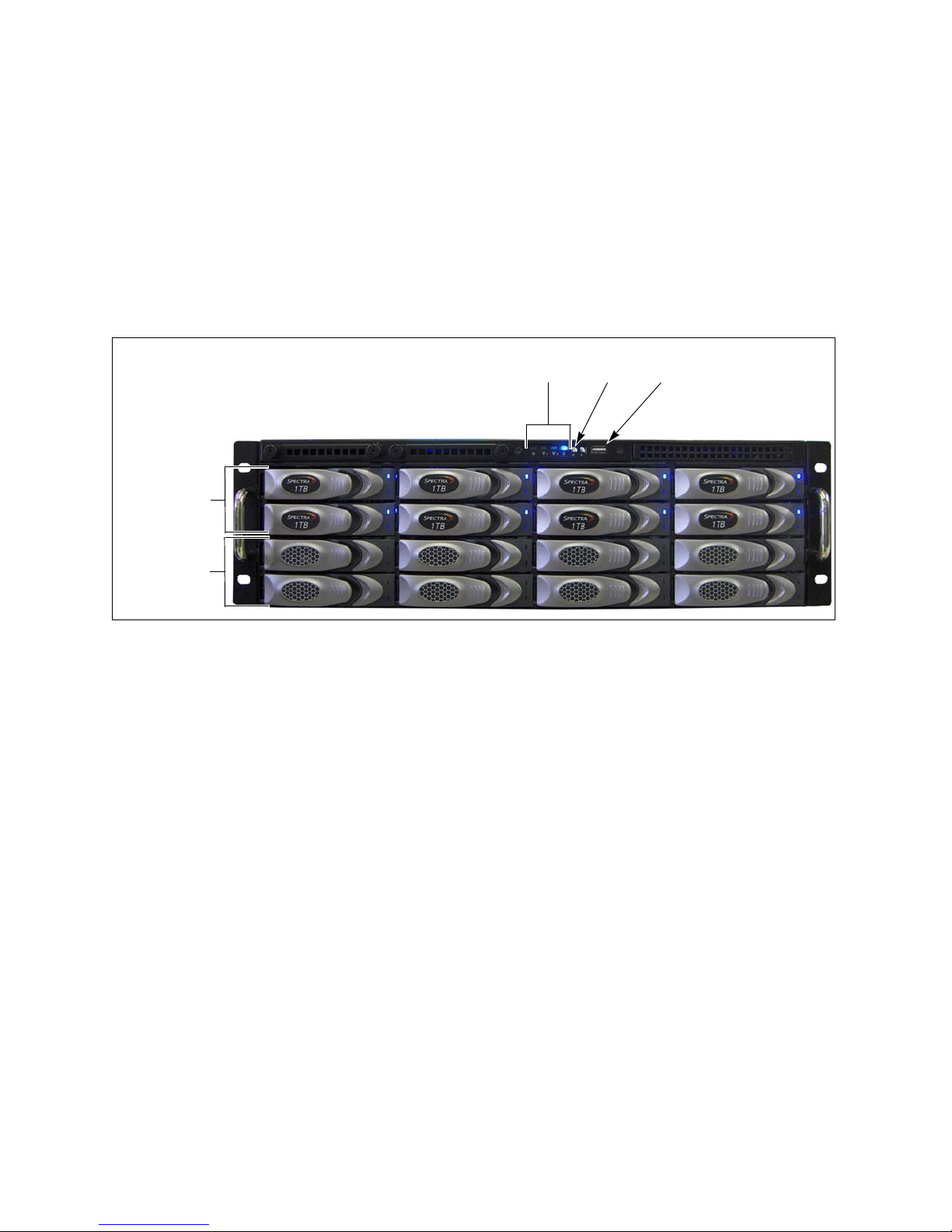
Status
LEDs Power
USB port
Data drives
Drive blanks
Components
The following sections show the locations of and briefly describe the nTier300 VTL’s
major front and rear panel components.
Front Panel
Figure 1-2 shows the major components on the front panel of the nTier300 VTL.
o
Figure 1-1 The front view of the nTier300 VTL (nTier300 VTL V80 shown, front cover removed).
RAID-protected data drives. The nTier300 VTL includes up to twelve high-
performance disk drives mounted on individual drive sleds. The drive sleds slide
into bays in the front of the nTier300 VTL enclosure and lock in place. The front of
each drive sled has a handle for removing the sled from the enclosure and a latch
for locking the drive sled in place. LEDs on each drive sled indicate the status of the
drive.
Drive blanks. When fewer than twelve data drives are installed, the bottom rows of
drive bays have drive blanks installed to prevent contaminates for entering the
enclosure and to maintain proper air flow. The drive blanks do not contain drives.
Status LEDs. The four status LED indicate the operating status of the drives and
chassis.
Power button. The recessed power button controls the main AC power for the
nTier300 VTL.
Universal Serial Bus (USB) port. The USB port can be used to connect a USB key
to the nTier300 VTL for saving configurations and uploading firmware packages.
13
Page 14

Chapter 1 – Spectra nTier300 VTL Overview
Power supply LEDs
N+1 power supplies
Integrated server
Power alarm
silence button
Rear Panel
Figure 1-2 shows the major components on the rear panel of the nTier300 VTL.
Note: Depending on the options you purchased, the rear panel of your
nTier300 VTL chassis may differ from the one shown in Figure 1-2.
o
Figure 1-2 The rear view of the nTier300 VTL (N+1 redundant power configuration
shown).
Integrated server. The powerful, integrated server uses a high-performance, dual-
core CPU running the FalconStor VTL software on the nTier300 VTL. See Integrated
Server on page 15 for a detailed description of the server components.
Power supplies. The standard nTier300 VTL configuration includes three power
supplies. The third power supply provides N+1 redundancy and fail-over
protection.
Each power supply has its own AC power connector. Cord locks on each power
cord secure the cord to prevent it from being inadvertently disconnected.
Each power supply has a single LED that lights to indicate when the power is on
and functioning normally.
Alarm silence button. If one of the three power supply fails or is not present, an
audible alarm sounds. To silence the alarm, press the red alarm silence button.
Pressing the button does not silence the alarm if two power supplies have failed or
if two power supplies are not connected to a power source. After the nTier300 VTL
has two working power supplies installed and connected to a power source, you
can use alarm silence button to silence the alarm.
14
Page 15
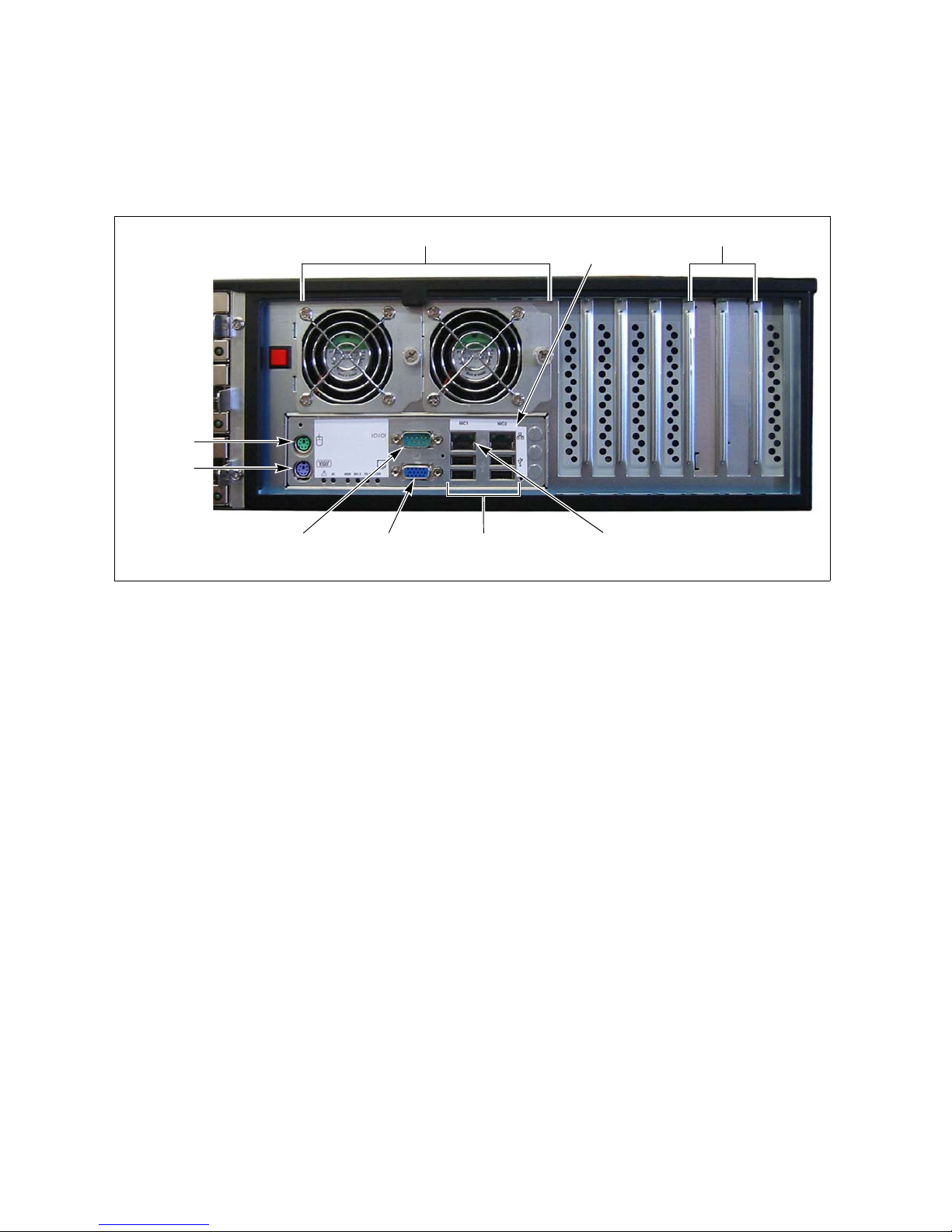
Integrated Server
Gigabit Ethernet
Monitor
connector
USB
port 1
Fans
Expansion slots
Mouse
Keyboard
Serial port
(COM2)
ports (4)
Gigabit Ethernet
port 2
Integrated Server
Figure 1-3 shows the rear panel components of the nTier300 VTL integrated server.
Figure 1-3 The nTier300 VTL integrated server rear panel components.
Keyboard, mouse, and monitor connectors. Used by SpectraGuard Support for
diagnostics and troubleshooting.
Serial port (COM2). Not currently used.
Gigabit Ethernet ports. The standard nTier300 VTL configuration includes two
1-Gigabit Ethernet ports. The Gigabit Ethernet ports can be used for iSCSI network
connections to the VTL, as well as for network connectivity for the FalconStor VTL
Console and BlueScale web interface used to configure, manage, and monitor the
nTier300 VTL.
USB ports. The USB ports can be used to connect a USB storage device to the
nTier300 VTL for saving configurations and uploading firmware packages. If
desired, you can use these ports to connect a USB mouse and a USB keyboard to
the nTier300 VTL integrated server.
Expansion slots. Two expansion slots accommodate one or two optional interface
cards to provide additional connectivity. You can install one 10GbE network
interface card (NIC) or up to two Fibre Channel or SCSI host bus adaptors (HBA),
which can be used to connect the nTier300 VTL to a tape library. The Fibre Channel
HBA can also be used to provide Fibre Channel network connectivity to the VTL.
Fans. The enclosure fans circulate air through the integrated server and the
nTier300 VTL enclosure.
15
Page 16
Chapter 1 – Spectra nTier300 VTL Overview
The nTier300 VTL Software
In addition to the operating system, the following software applications are installed
on the nTier300 VTL server:
FalconStor software
Spectra Logic BlueScale web interface
FalconStor Software
The FalconStor software provides the Virtual Tape Library (VTL) and Single Instance
Repository (SIR) deduplication functionality for the Spectra nTier300 Deduplication
VTL. For detailed configuration and use information, read the Implementing nTier
Deduplication guide, which is included as a PDF on the nTier Deduplication CD.
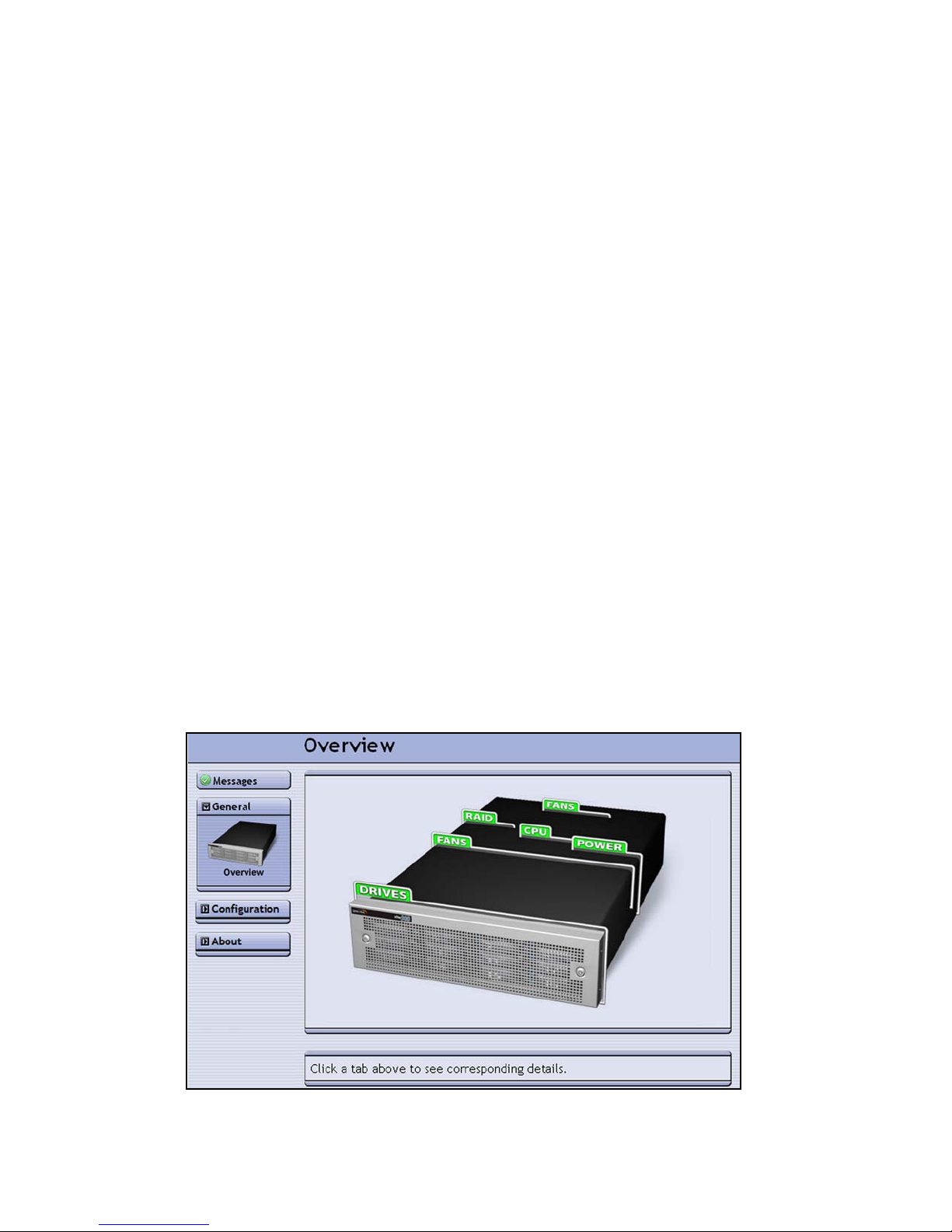
Spectra BlueScale Web Interface
The BlueScale web interface (shown in Figure 1-4) provides an interface for monitoring
the operational status of nTier300 VTL system components, including the drives and
the RAID controller battery backup. You can also configure IP network connections
and prepare disks for maintenance. The BlueScale web interface supports the
following standard web browsers.
Microsoft Internet Explorer versions 6.0 and 7.0
Mozilla FireFox 2.0
To learn more, see Using the BlueScale Web Interface on page 40.
Figure 1-4 The Overview page of the BlueScale web interface.
16
Page 17

2 Installing the nTier300 VTL
This chapter covers the following information:
Preparing for the Installation
Unpacking the nTier300 VTL on page 18
Rackmounting the nTier300 VTL on page 22
Installing the Data Drives on page 30
Connecting Cables and Powering On on page 32
Install the Front Cover on page 34
Preparing for the Installation
Before unpacking and installing the Spectra nTier300 VTL, confirm the following:
The installation location has adequate clearance for ventilation, minimal dust and
debris, and proximity to an appropriate AC power source.
The appropriate network connections are available. The nTier300 VTL requires a
minimum of one Ethernet connection to provide the FalconStor VTL Console access
to the nTier300 VTL and for accessing the BlueScale web interface. It also requires
network connections to the backup servers that will be accessing the nTier300 VTL
for data storage.
Ethernet port 1 is preconfigured to use DHCP addressing. Identify a network
with a properly configured DHCP/DNS server.
Ethernet port 2 is preconfigured with an IP address of 192.168.1.2. If your
network does not have a DHCP/DNS server, identify a network connection that
is compatible with this IP address.
Note: The Ethernet port used for accessing the BlueScale web interface
and the VTL Console can also be used to provide network
connectivity to the VTL from the backup server for data storage.
17
Page 18

Chapter 2 – Installing the nTier300 VTL
An appropriate rack is assembled and placed near the AC power outlets and
network connections.
The nTier300 VTL chassis occupies 3U (5.25 inches) of rack space. It is designed to
fit in a standard 19-inch rack. An additional 3 inches to the depth may be required
to allow for cable clearance. Using a 4-post rack that is at least 47 inches (120 cm)
deep is recommended.
Note: The use of two-post “telco” racks is not supported.
Caution: The rack must be located on a level, hard-surfaced floor such as
cement or tile. Do not place the rack on a carpeted floor or
anywhere else that poses risk for static discharge that could
damage your appliance and its drives.
Unpacking the nTier300 VTL
The Spectra nTier300 VTL and its drives are shipped in a cardboard box attached to a
pallet. The only tool needed to unpack the box is a pair of scissors.
Prepare the Unpacking Location
Note: Make sure that you have a work space area prepared before you
remove the nTier300 VTL from its shipping box.
Set the pallet with the box in a location that gives you adequate clearance around and
above the Spectra nTier300 VTL box so that you can safely unpack it. Make sure that
you have a sturdy work surface near where you will install it. The work surface should
be large enough to accommodate the nTier300 VTL chassis and other components.
18
Page 19
Unpacking the nTier300 VTL
Tip n Tell
Shockwatch
Outer lid
Unpack the Components
Save all the original packing materials in case it is necessary to ship or move the
nTier300 VTL later.
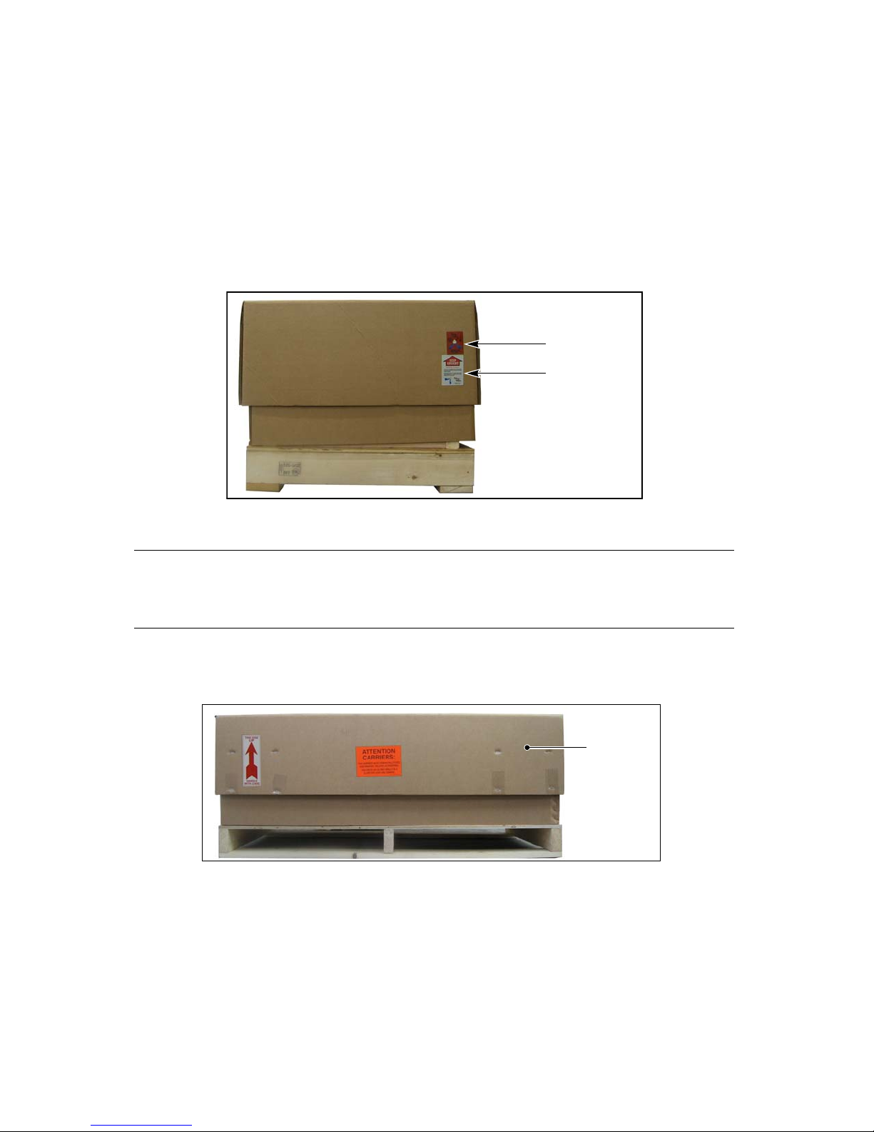
1. Use scissors to cut away the plastic wrap surrounding the nTier300 VTL shipping
box.
2. Check the Tip N Tell™ and Shockwatch® indicators to ensure that the nTier300 VTL
has not been improperly handled, before proceeding (Figure 2-5).
Figure 2-5 Check Tip n Tell and Shockwatch.
Caution: Do not unpack the nTier300 VTL or its drives if the Tip N Tell or
Shockwatch indicator has been tripped. Contact both the
shipping company and Spectra Logic to report the problem.
3. Use scissors to cut the straps securing the nTier300 VTL box to the shipping pallet.
4. Remove the outer lid from the shipping box (Figure 2-6).
Figure 2-6 Remove the outer lid.
19
Page 20

Chapter 2 – Installing the nTier300 VTL
1. Remove top foam insert.
3. Remove the foam tray holding
the front cover, rack-mount kit,
power cables, anti-static kit, and
documentation.
4. Lift the nTier300 VTL
chassis (bagged) from the
internal box. Leave the
bottom foam insert in the
box.
2. Remove two foam inserts holding
the drives. The number of drives
depends on the configuration
ordered.
5. Refer to Figure 2-7 to remove the drives, accessories, and nTier300 VTL chassis
from the shipping box. Place the chassis and the drives on your work surface.
Warning: The nTier300 VTL weighs approximately 54 lb. (25 kg) without
drives installed. Use extreme caution when moving it. Always
use two people, one on each side, when lifting or moving it.
Warnung: Die nTier300 VTL wiegt ca 25 kg., ohne Laufwerke installiert.
Verwenden Sie extreme Vorsicht walten lassen, wenn sie
abwandern. Benutzen Sie immer zwei Personen, eine auf jeder
Seite, beim Heben oder Fortbewegen.
Caution: Leave the drives in their anti-static bags until you have
unpacked and installed the chassis in a rack. Always wear an
anti-static wristband attached to an unpainted metallic surface
when handling the drives. An anti-static wristband is included
with the accessories.
Figure 2-7 Unpacking the nTier300 VTL.
6. Save the box, anti-static bags, and foam packaging in case you need to re-ship the
nTier300 VTL for any reason.
20
Page 21

Unpacking the nTier300 VTL
Inventory the Components
Unpack and identify the components that shipped with the nTier300 VTL using the
following table for reference.
Component Description
Rack mounting kit Included in the accessory box. The rack mounting kit includes all the
components required to mount the nTier300 VTL in a standard 4-post,
19-inch rack.
Antistatic
wristband
Power cords Included in the accessory box. Three power cords are provided with the
Drives The number of drives depends on the configuration you ordered. Each
Front cover and
keys
Software licenses,
software activation
keys, and
documentation
Included in the accessory box. An antistatic wristband to be worn when
handling the disk drives.
standard nTier300 VTL configuration (for either 110 VAC or 220 VAC
operation). See Power Cord Specifications on page 69 for information
about the power cords.
drive is mounted on a drive sled.
Note: Any drive blanks are shipped pre-installed.
The front cover protects the drives and prevents unauthorized access.
The following documentation, licenses, and Spectra license keys are
included in the accessory box:
A license key for the nTier Deduplication VTL software
Spectra nTier300 VTL Deduplication VTL documentation:
Implementing nTier Deduplication
Spectra nTier300 Virtual Tape Library Appliance Installation Guide
(this guide)
21
Page 22
Chapter 2 – Installing the nTier300 VTL
Rail assemblies
Small screws
Rackmounting the nTier300 VTL
Install the nTier300 VTL in a standard 4-post, 19-inch rack using 3 units (3U) of rack
space.
Warning: If you are not installing any other equipment in the rack, install
the nTier300 VTL near the bottom of the rack to prevent the
rack from being top-heavy.
Warnung: Wenn Sie nicht die Installation ein anderes Gerät im Rack,
installieren Sie die nTier300 VTL in der Nähe der Unterseite des
Schranks zu verhindern, dass der Schrank von der kopflastigen.
Before You Begin
Obtain the following tools and equipment:
#2 Phillips screwdriver, magnetic if available
Measuring tape (recommended)
Level (recommended)
Identify the location where you will install the nTier300 VTL.
Assemble the rack, if necessary.
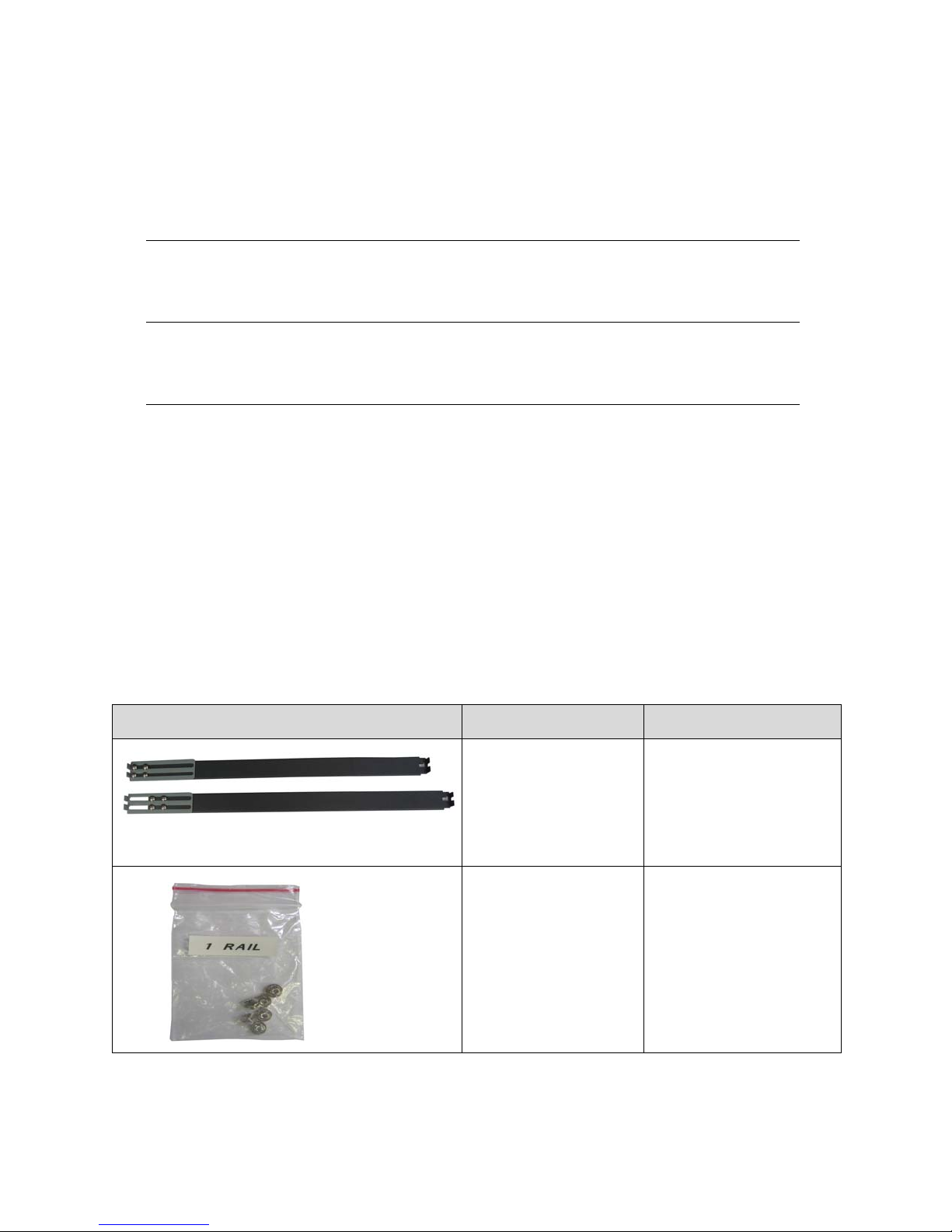
Unpack the rack mount kit and identify the components:
Component # Required Use
2 rail assemblies Mount chassis in rack.
Bag labeled
6 or more screws
1 RAIL.
Each assembly includes:
Rail
Slider
Extender plate
Attach rail sliders to
chassis.
22
Page 23
Rackmounting the nTier300 VTL
Small nut plates
and screws
Large nut plates
and screws
Clip nuts
and screws
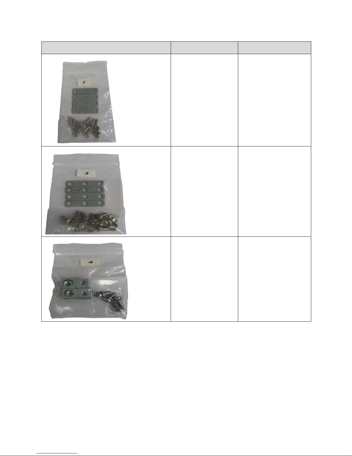
Component # Required Use
Bag labeled 2
4 small nut plates
12 (or more) screws
Bag labeled
4 large nut plates
12 (or more) screws
3
Attach rail assemblies to
rack.
Attach rail assemblies to
rack.
Bag labeled
4 clip nuts
4 screws
4
Secure nTier300 VTL to
rack.
23
Page 24
Chapter 2 – Installing the nTier300 VTL
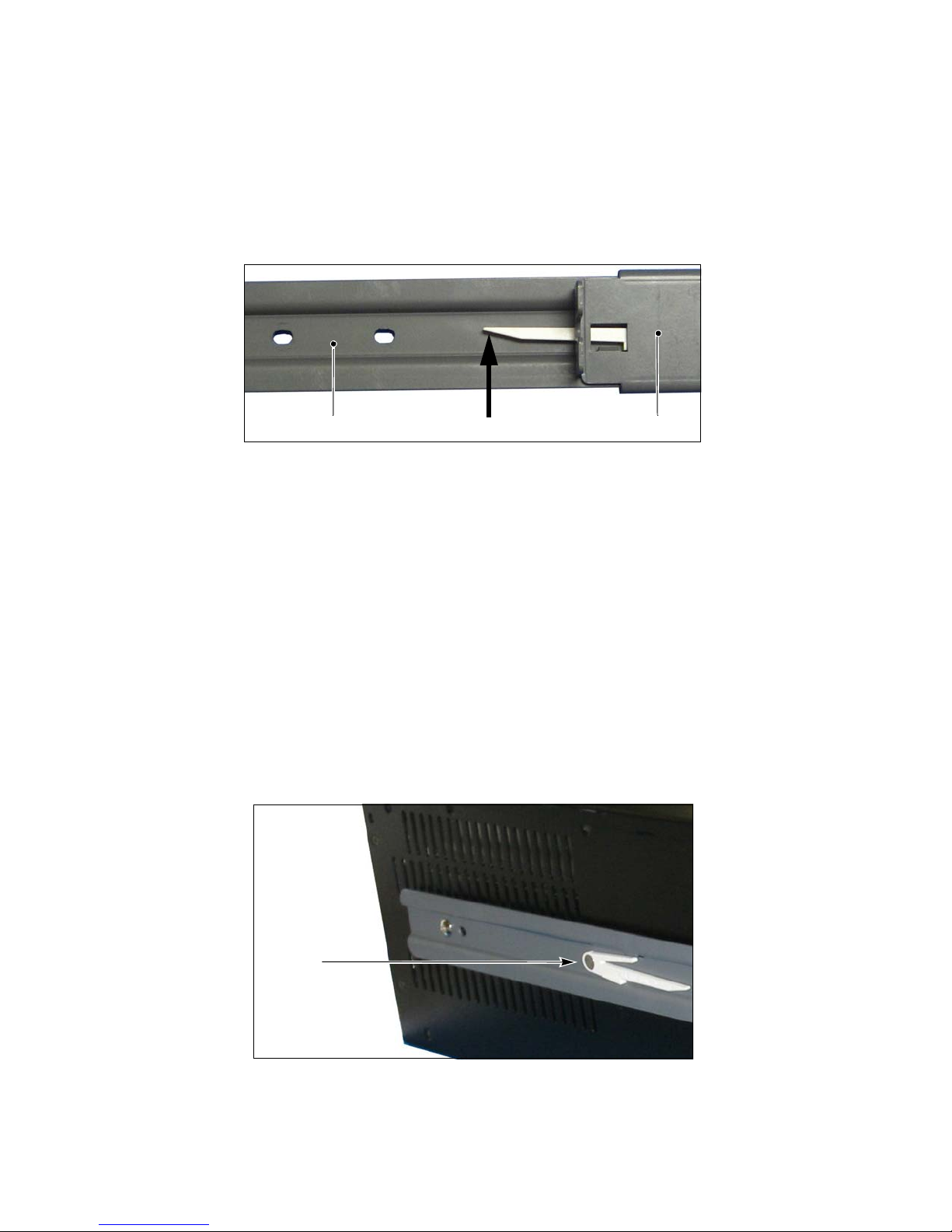
Press up to release safety latchSlider Outer rail
Latch
Rear of chassis
Prepare the Rails
Disassemble the rail assemblies. Each assembly consists of an outer rail and an inner
slider.
1. Extend the slider from the outer rail until the safety latch is visible, as shown in
Figure 2-8.
Figure 2-8 The safety latch and mounting holes.
2. Press up on the latch as shown in Figure 2-8 to release the latch.
3. Pull the slider completely out of the outer rail.
4. Repeat steps 1–3 for the second rail assembly.
Install the Sliders on the Chassis
1. Remove the nTier300 VTL chassis from its bag and place it on a sturdy work surface
where you can reach both sides of the chassis. Having two people for this task
simplifies lifting and moving the chassis.
2. Position a slider against one side of the chassis with the latch toward the rear of the
chassis, as shown in Figure 2-9. Make sure the safety latch is visible.
o
Figure 2-9 Position the latch toward the rear.
24
Page 25
Rackmounting the nTier300 VTL
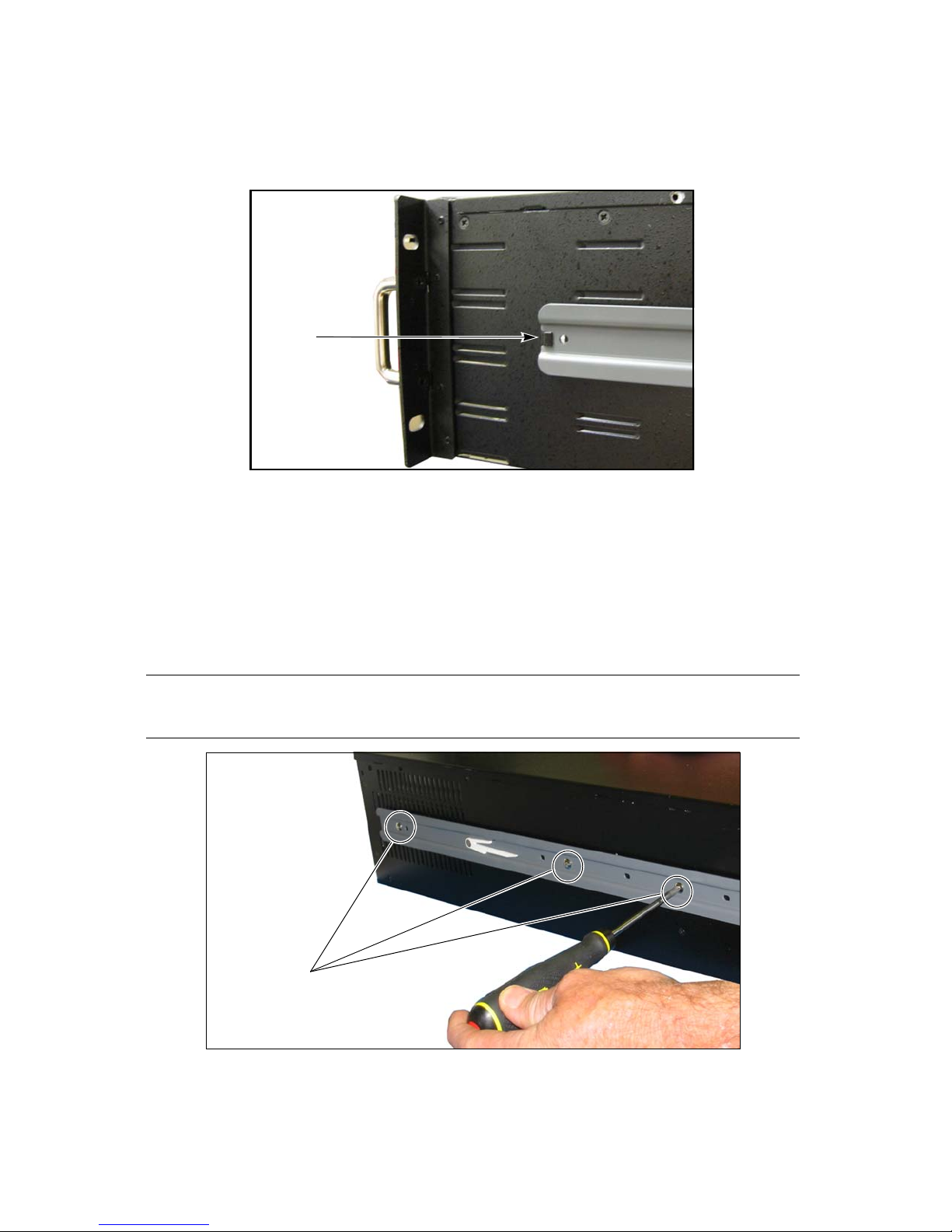
Tab
Front of chassis
Screws
3. Slide the end of the slider (furthest from the latch) under the tab near the front of
the chassis so that the tab fits into the notch on the end of the slider, as shown in
Figure 2-10.
o
Figure 2-10 Insert the slider under the tab.
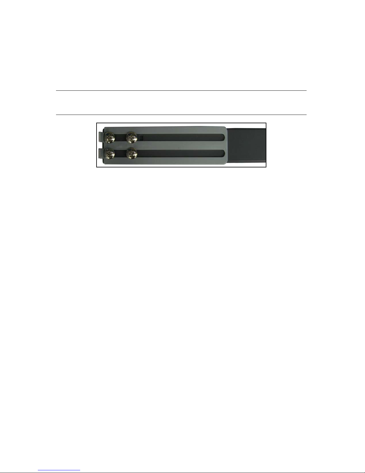
4. With the screw holes in the slider aligned with the chassis screw holes, use a #2
Phillips screwdriver to install the screws from bag 1.
Screw one screw into each of the circled three holes, as shown in Figure 2-11. This
secures the slider to the chassis. Tighten the screws snugly. (If the circled holes
don’t align properly with chassis screw holes, install the three screws from bag 1
into other screw holes in the slider.)
Note: There are extra screw holes in the slider. Only three of them are
needed to attach it to the chassis.
o
5. Repeat Steps 2–4 to attach the second slider to the other side of the chassis.
Figure 2-11 Attach the slider to the chassis.
25
Page 26
Chapter 2 – Installing the nTier300 VTL
Adjust the Length of the Outer Rails
1. Make sure the extender on the outer rail can slide a little to extend the length of the
rail. If necessary, loosen or tighten the screws attaching the extender to the rail.
Refer to Figure 2-12 to see a close-up of the rail with the extender attached.
Note: Using a measuring tape simplifies determining the length required
for the rails to fit inside the rack.
o
Figure 2-12 Extender screwed into rail end.
2. Hold one of the remaining rails against the rack side, with the extender nearest the
back of the rack.
3. Adjust the extender so that it just fits in the inside distance from the front mounting
holes of your rack to the back mounting holes.
4. Tighten the four screws holding the extender to the rail.
5. Repeat for the other rail.
Install the Outer Rail in the Rack
1. Examine the mounting holes in your rack and select either bag 2 or bag 3, that has
the set of nut plates and screws that best match these holes.
2. Determine where to install the nut plates on the rack. The plates must be
positioned to provide at least 2 inches of clearance below the bottom edge of the
plate.
26
Page 27
Rackmounting the nTier300 VTL
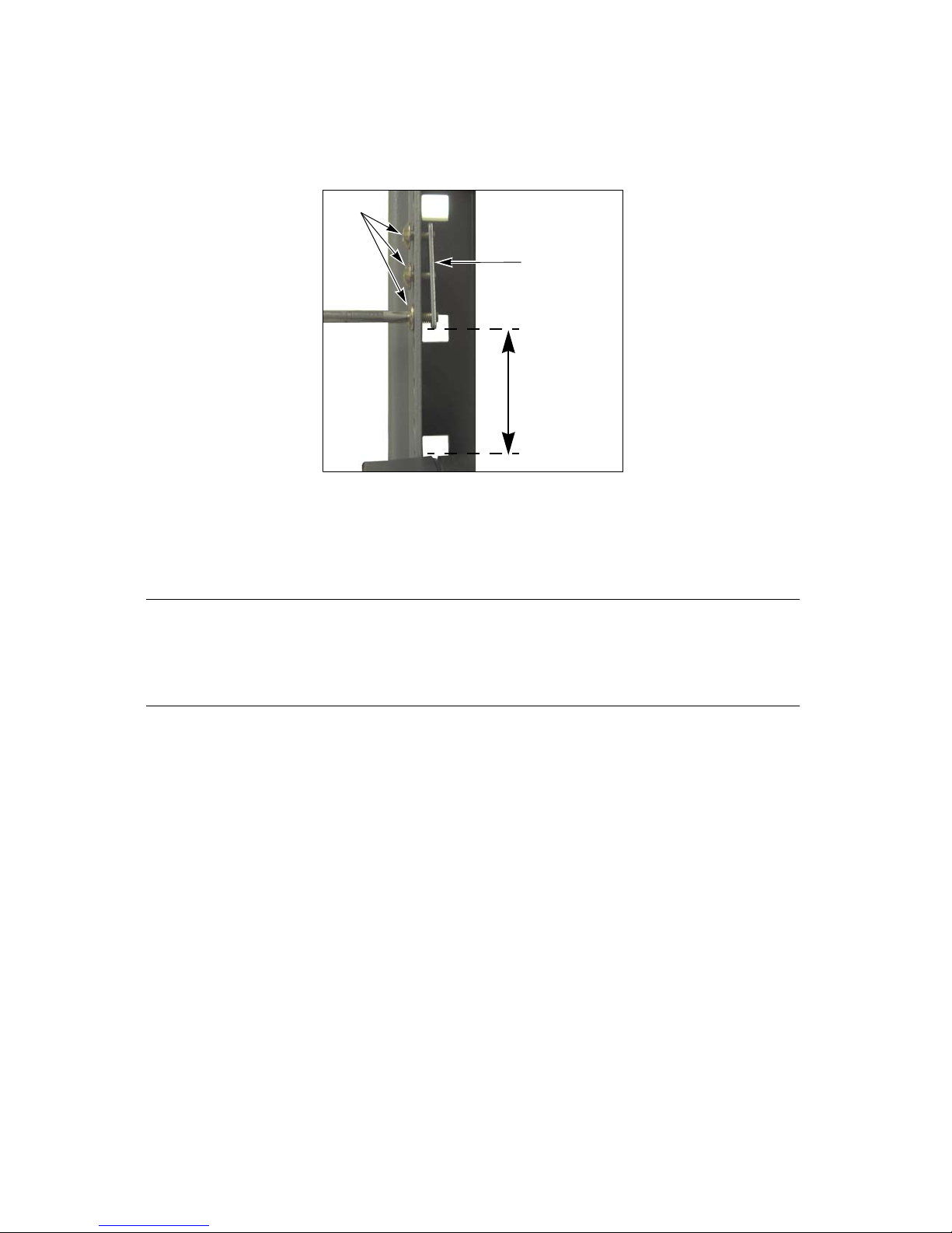
2 inches
Nut Plate
Screws
3. Position a nut plate behind one rack post at the desired position, then use a
#2 Phillips screwdriver to screw three ½-inch screws into the plate, as shown in
Figure 2-13. Tighten the screws only enough to hold the plate in place.
o
Figure 2-13 Loosely attach the nut
plate to the rack.
4. Repeat Step 3 to install the nut plates on the each of the other three posts of the
rack.
Note: Make sure that the nut plates are installed at the same level on all
four posts. Otherwise the rails will not be level when they are
installed. Using a level simplifies positioning the nut plates so that
the rails will be level.
27
Page 28

Chapter 2 – Installing the nTier300 VTL
Tabs
Front
(behind post)
Rear
Tab s
Clip nut
Clip nut
Empty hole
Empty hole
Mounting screws
for nut plate
5. Fit the tabs on one rail extender between the nut plate and one of the back rack
legs. Then, fit the front tabs on the rail between the nut plate and corresponding
legs on the front of the rack (see Figure 2-14). Tighten all three screws to secure the
nut plate to the rack.
o
Figure 2-14 Insert the rail tabs between the nut plate and the rack.
6. Repeat Step 5 to attach the second outer rail to the rack. Set aside any leftover
screws and parts.
7. On the front of the rack, attach two clip nuts, from bag 4, to each leg. Place one
above and another below the rails, with one empty hole separating each clip nut
from the nut plate mounting screws.
o
Figure 2-15 Attach clip nuts to the front of the rack.
28
Page 29

Rackmounting the nTier300 VTL
Install the nTier300 VTL into the Rack
1. Lift the nTier300 VTL and slide it onto the rails in the rack until the mounting ears
on the front of the chassis fit against the rack, with the mounting ear screw holes
directly over the clip nut holes (see Figure 2-16).
Warning: The nTier300 VTL weighs approximately 54 lb. (25 kg) without
drives installed. Use extreme caution when moving it. Always
use two people, one on each side, when lifting or moving it.
Warnung: Die nTier300 VTL wiegt ca 25 kg., ohne Laufwerke installiert.
Verwenden Sie extreme Vorsicht walten lassen, wenn sie
abwandern. Benutzen Sie immer zwei Personen, eine auf jeder
Seite, beim Heben oder Fortbewegen.
Caution: A fully loaded chassis is heavy. Most of the weight is toward the
front of the chassis.
Figure 2-16 Slide the chassis into the rack.
29
Page 30

Chapter 2 – Installing the nTier300 VTL
Screw
Screw
Mounting ear
2. Use a #2 Phillips screwdriver to install the two clip nut screws in each mounting ear
to secure the chassis to the rack (see Figure 2-17).
Figure 2-17 Secure the chassis to the rack (left
side shown)
Installing the Data Drives
Each of the nTier300 VTL’s data drives is mounted on a drive sled for easy installation.
The drive sled includes a handle and latch to secure the drives in the chassis. The
chassis has 16 drive bays. Only the top eight bays are used; the remaining bays are
filled with drive blanks.
You do not need to install the drives into the drive bays in any particular order. The
drive mapping for the RAID volume in the nTier300 VTL is dynamic. The system
determines the position of each drive during the first system boot and automatically
updates the drive locations to preserve that volume’s preconfigured RAID 6 volume.
Caution: Do not plug the power cords into the nTier300 VTL or turn on
the power until you finish installing all of the drives for the first
time. If you install the drives with the nTier300 VTL powered
on, the RAID controller immediately begins rebuilding the RAID
volume in the blade, which may destroy the preconfigured
RAID 6 volume.
30
Page 31

Installing the Data Drives
Sled handle
(open position)
Latch
Use the following steps to install the drives.
1. Put on the provided anti-static wristband and attach it to an unpainted metallic
surface.
Caution: Any damage to the Spectra nTier300 VTL caused by failure to
protect it from electrostatic discharge (ESD) voids the
nTier300 VTL’s warranty. To protect the nTier300 VTL drives
from damage:
Wear an anti-static wristband, properly grounded, throughout
the procedure. If a wristband is not available, touch a known
grounded surface, such as the unpainted metal chassis.
Leave the drives in their anti-static bags until you are ready to
install them.
Do not place un-bagged drives on any metal surfaces.
Do not power on the nTier300 VTL until all of the drives are
installed.
2. Take one drive from the box and remove it from its anti-static bag.
3. Slide the latch on the drive sled the right to release it, then rotate the handle
outward and to the left (Figure 2-18.
o
Figure 2-18 Install the drive sled into the nTier300 VTL.
4. With the drive handle in the open position, slide the drive sled into the chassis until
the front of the drive sled is flush against the front of the chassis. The drive sled
slides in easily; do not force it.
31
Page 32

Chapter 2 – Installing the nTier300 VTL
Power
connectors
Ethernet port 1
Ethernet port 2
5. When the drive sled is in position, push the handle inward and to the right until it
locks in place. An audible click indicates that the drive sled is locked into position.
Note: The latch occasionally sticks in the open position. If this happens,
simply push it to the left and press the handle inward to lock the
drive into place.
6. Repeat Steps 2–5 to install all of the remaining drives.
Connecting Cables and Powering On
After installing the drives, you are ready to connect the cables to the system and
perform the initial power-up.
Figure 2-19 Connect the cables to the back panel.
1. Connect an Ethernet cable to either Ethernet port 1 or 2 on the rear panel. Connect
the other end of the cable to an active network over which a computer running the
FalconStor VTL Console can access the nTier300 VTL. This connection also provides
access to the BlueScale web interface using a web browser.
Ethernet port 1 is preconfigured to use DHCP addressing. Use the VTL Console
to view the IP address assigned by the DHCP server.
Ethernet port 2 is preconfigured with an IP address of 192.168.1.2. Use this port
if your network does not have a DHCP server.
32
Page 33

Connecting Cables and Powering On
2. Connect the interface cable from your backup server to the appropriate connector
on the nTier300 VTL rear panel. See Figure 1-3 on page 15 for the location of the
connectors and expansion slots on the back panel.
If the backup server is on an iSCSI network, connect an Ethernet cable from
your switch to one of the Ethernet ports on the nTier300 VTL rear panel. If the
VTL Console is installed on your Windows-based backup server, the port you
use to connect to the backup server can also be used by the VTL Console and
for accessing the BlueScale web interface.
If the backup server is on a Fibre Channel (FC) network, connect an FC cable
from your switch to an optional FC network interface card (NIC) installed in the
nTier300 VTL. The VTL Console identifies the top port as
Fibre.Channel.Adapter.100 and the bottom port as Fibre.Channel.Adapter.101.
If the backup server is on a 10 Gigabit Ethernet (10 GigE) network, connect a
cable from your switch to an optional 10 GigE NIC installed in the nTier300 VTL.
3. If desired, connect the nTier300 VTL to a physical library, a standalone tape drive,
or another nTier VTL appliance.
If your physical library, tape drive, or other nTier VTL appliance is on an Fibre
Channel network, connect a cable from your switch to an optional Fibre
Channel NIC installed in the nTier300 VTL.
If your physical library, tape drive, or other nTier VTL appliance is on an iSCSI
or 10 Gigabit Ethernet (10 GigE) network, connect an Ethernet cable from your
switch to one of the unused Ethernet ports on the nTier300 VTL rear panel or to
a 10 GigE NIC installed in the nTier300 VTL.
If your physical library or tape drive uses a SCSI interface, connect a SCSI cable
from a SCSI host bus adapter (HBA) installed in the nTier300 VTL to your library
or tape drive.
4. Connect the AC inputs on the nTier300 VTL power supplies to an appropriate AC
power source.
a. Connect a power cord to each of the power supply connectors on the back
panel.
b. Push the cord lock on each connector to the left so that it fits over the power
cord, locking it in place.
c. Plug the other end of each cord to an AC power outlet.
33
Page 34

Chapter 2 – Installing the nTier300 VTL
Power button
Cavity for the handle
Locking tab in
unlocked position
on front of chassis
5. Using a stylus or other similar non-conductive object, press the recessed power
button on the front panel (Figure 2-20).
6. Wait for the system to complete its power-on sequence.
o
Figure 2-20 Press the recessed power button.
Install the Front Cover
The front cover secures the drives to prevent unauthorized removal.
1. Insert a key into the lock on each side of the front cover.
2. Examine the back of the cover. Using the keys, position of the locking tabs on each
end so they are in the unlocked position (Figure 2-21).
Figure 2-21 Set the locking tab to the unlocked
position.
3. Hold the edges of the cover and orient it so that the chassis handles fit into the
cavities on each side of the cover.
4. Push in on each key and turn it to the horizontal (locked) position to secure the
cover to the chassis.
34
Page 35

Next Steps
Next Steps
Your nTier300 VTL hardware is installed. For information about using the
nTier300 VTL, read the following:
Read the Implementing nTier Deduplication guide to learn about installing and
using the FalconStor software.
If you have not already done so, install the VTL Console on a Windows-based
computer on the same network as the nTier300 VTL.
The default user name for the VTL Console is root, the default password is
spectra.
If you connected the computer running the VTL Console to the nTier300 VTL
using Ethernet port 1, use the VTL Console to determine the IP address assigned
to the port by your DHCP server. You can then use this address to access the
BlueScale web interface.
If you connected the computer running the VTL Console to the nTier300 VTL
using Ethernet port 2, use IP address 192.168.1.2 to connect to the server
through the VTL Console and to access the BlueScale web interface.
Use the VTL Console to configure the connections between the nTier300 VTL
and a backup server and to configure, operate, and monitor the virtual tape
libraries. You also configure the deduplication functionality using the VTL
Console.
Read Chapter 3 – Using the nTier300 VTL BlueScale Web Interface in this guide to
learn about accessing and using the BlueScale web interface. This chapter also
provides information about setting the IP addressing for the Ethernet ports using
the BlueScale web interface and about restarting or shutting down the
nTier300 VTL hardware.
Read Chapter 4 – Maintenance to learn about replacing a data drive in the
nTier300 VTL.
35
Page 36

Chapter 2 – Installing the nTier300 VTL
Notes
36
Page 37

3 Using the nTier300 VTL
Power button
BlueScale Web Interface
This chapter describes how to use the BlueScale web interface and the blade operator
panels to configure and monitor the Spectra nTier300 VTL.
Powering On the Spectra nTier300 VTL on page 37
Accessing the BlueScale Web Interface on page 38
Using the BlueScale Web Interface on page 40
Monitoring the Status of Components on page 45
Viewing and Configuring IP Addresses on page 48
Restarting or Shutting Down the nTier300 VTL on page 50
Powering On the Spectra nTier300 VTL
To power on the nTier300 VTL, use a stylus or other similar non-conductive object to
press the recessed power button on the front panel (Figure 3-1).
Note: If the front cover is installed, remove it as described in Remove the
Front Cover on page 55.
o
Figure 3-1 Press the recessed power button.
37
Page 38

Chapter 3 – Using the nTier300 VTL BlueScale Web Interface
Wait while the nTier300 VTL completes its power-on sequence, which takes about five
minutes, depending on the nTier300 VTL configuration. During the power-on
sequence, the nTier300 VTL initializes all of its installed components and starts the
BlueScale web server.
Caution: Do not use the power button to turn off the nTier300 VTL
unless you are specifically instructed to do so by SpectraGuard
Support. Instead, use the shutdown procedure described in
Restarting or Shutting Down the nTier300 VTL on page 50.
Accessing the BlueScale Web Interface
The BlueScale web interface lets you configure network connections to the
nTier300 VTL, monitor the status of system components, including the drives and the
battery backup, and view system-wide metrics, monitor system health.
Use the following steps to connect to the BlueScale web interface.
1. Depending on which Ethernet port you used to connect the nTier300 VTL to the
network, determine the IP address of that port is (see Connecting Cables and
Powering On on page 32 and the Implementing nTier Deduplication guide for
information).
2. Open a web browser on a computer connected to the same network as the
nTier300 VTL.
38
Page 39

Accessing the BlueScale Web Interface
3. Enter the IP address for Ethernet port on the nTier300 VTL in the browser address
bar using the form https://nnn.nnn.nnn.nnn, where nnn.nnn.nnn.nnn is
the IP address.
Note: The BlueScale web interface uses a secure internet connection.
You must prefix the IP address with https:// instead of just
entering the IP address.
A warning about the web site’s security certificate displays.
Figure 3-2 shows an example warning from Internet Explorer 7.
The format of the warning may be different with the web browser
you are using. The warning displays because the nTier300 VTL
does not have a valid security certificate.
The absence of the certificate does not affect functionality. If you
want to eliminate this warning, purchase and install your own
security certificate from www.verisign.com, www.instantssl.com,
or another SSL certificate vendor.
Figure 3-2 The web site security certificate warning shown in Internet Explorer 7.
39
Page 40

Chapter 3 – Using the nTier300 VTL BlueScale Web Interface
4. Select “Continue to this website” to ignore the warning and display the Overview
page (Figure 3-3).
5. To exit the BlueScale web interface, simply close the browser to end the session.
Figure 3-3 The Overview page.
Using the BlueScale Web Interface
The BlueScale web interface lets you configure the nTier300 VTL network connections
and monitor the status of system components. The BlueScale web server starts
automatically when you power on the nTier300 VTL. After the nTier300 VTL completes
its power-on sequence, log into the BlueScale web interface as described in Accessing
the BlueScale Web Interface on page 38.
40
Page 41

Using the BlueScale Web Interface
Additional
menus
Current
menu
Menus
The Menu panel (shown in Figure 3-4) appears along the left edge of each page. Menu
buttons in this panel let you navigate through the available menus to select options.
Selecting a menu button expands the menu to display the available options.
Figure 3-4 The Overview page of the BlueScale web interface.
The following table provides an overview of the options available under each menu.
The page for the previously selected option remains displayed until you select another
option, either from the same menu or another one.
Menu Available Options
Messages
General
Configuration
Status—A status icon on the Messages button indicates the highest
severity level for the unread messages. See BlueScale Status Icons for a
description of the status icons.
Unread messages—The number of unread messages (if any) displays on
the Message button. Selecting the Messages button displays a list of all
the current messages (see Viewing Messages on page 42). The status icon
next to the message indicates the severity level.
The General menu (shown in Figure 3-4) accesses the Overview screens.
These screens provide the current status for all of the major components in
the nTier300 VTL. Selecting one of the tabs on the graphic highlights the
selected component and displays current status information (see Monitoring
the Status of Components on page 45).
The Configuration menu accesses controls for configuring the IP address and
other settings for each Ethernet port, NIC, or HBA installed in the
nTier300 VTL (see Viewing and Configuring IP Addresses on page 48).
About
Displays the BlueScale firmware version and the nTier300 VTL serial number.
41
Page 42

Chapter 3 – Using the nTier300 VTL BlueScale Web Interface
BlueScale Status Icons
Icons indicate the status of a component and the highest severity level for any system
messages, as described in the following table. Click the icon to view the related system
messages (see Viewing Messages on page 42).
Icon Meaning
Component OK. The component is functioning correctly.
Information. An informational message about a system component is available. Check
messages to determine the component.
Warning. A system component requires attention. Check messages to determine the
component.
Error. A system component has experienced an error condition. Check messages to
determine the component and its error condition.
Unknown. The status of the system component cannot be determined. Check messages
to determine the component.
Viewing Messages
The Messages button lets you view all of the messages posted by the system. The icon
on the Messages button indicates the highest severity level of any unread
(unacknowledged) messages. The number on the left side of the button, if any, shows
the number of unread messages. For example, the Messages button shown in
Figure 3-5 indicates that there are 30 unread messages. The Error icon indicates that at
least one of the messages is an error notification.
Reading Messages
Use the following steps to view the messages.
1. Log into the BlueScale web interface (see Accessing the BlueScale Web Interface on
page 38)
42
Page 43

Using the BlueScale Web Interface
2. Select the Messages button to display the Messages page (Figure 3-5).
Figure 3-5 The Messages page.
Unread Messages shows the number of unread messages.
Previously Read Messages shows the number of messages that have been
marked as read, if any.
3. Select Unread Messages to expand the list of unread messages (Figure 3-6).
Figure 3-6 Unread Messages list in the Messages page.
Pay extra attention to any message flagged with the Warning or Error icon, and
follow any recommended steps. Contact SpectraGuard Support if you need help
(see Contacting Spectra Logic on page 5).
43
Page 44

Chapter 3 – Using the nTier300 VTL BlueScale Web Interface
Marking Messages as Read
The nTier300 VTL can store hundreds of messages at a time. After you read and resolve
errors or issues described in all of the unread messages, scroll down (if necessary) to
the bottom of the new messages list and select Mark All as Read (Figure 3-7). The
number and the status icon shown on the Messages button are updated to reflect the
status of any new messages. Selecting Mark All as Read moves the messages from the
Unread Messages list to the Previously Read list.
Figure 3-7 Select Mark All as Read to move messages to the
Previously Read list.
Note: You cannot delete messages. The nTier300 VTL automatically
deletes the oldest messages as space is required, retaining the most
recent messages.
44
Page 45

Monitoring the Status of Components
Component status tabs
Monitoring the Status of Components
The tabs on the Overview page (Figure 3-8) provide an at-a-glance system status. Each
tab represents a group of related components. From this screen, you can display more
detailed status information for individual components. The ability to monitor
components status using the BlueScale web interface is especially useful when your
nTier300 VTL is operating in a “lights out” data center.
Note: To ensure that you know the status of the nTier300 VTL
components in a lights out environment, make sure you routinely
check the BlueScale web interface.
Figure 3-8 The Overview page of the BlueScale web interface.
45
Page 46

Chapter 3 – Using the nTier300 VTL BlueScale Web Interface
The following table describes the types of status information on each component tab.
Tab Shows...
Drives
Fans
RAID
CPU
Power
Overall status for all drives
Status of each drive
Status of midplane fans
Status of the rear panel fans
HBA RAID controller status
HBA batteries (for RAID write cache) status
Logical volume status and information
CPU status
Power supply status
The color of the tab indicates the overall status of that group of components.
Green—The components in the group are operating properly (Figure 3-9).
Yellow—A component in the group requires attention.
Red—A component in the group is in an error state (Figure 3-10).
Figure 3-9 The Overview page (all systems are
operating properly).
46
Figure 3-10 Overview page, DRIVES require
attention.
Page 47

Monitoring the Status of Components
To view the detailed status information for all of the components in a group, click
the tab. For example, clicking the red DRIVES tab in Figure 3-10 changes the
graphic to show the components associated with DRIVES. Selecting Drives from the
list below the graphic expands the page to show a list of the drives (Figure 3-11) in
the system. An icon next to each drive indicates the status.
Note: You may need to scroll through the page to view all of the
information.
Figure 3-11 Detailed information about Drive status.
47
Page 48

Chapter 3 – Using the nTier300 VTL BlueScale Web Interface
Viewing and Configuring IP Addresses
The nTier300 VTL includes two onboard Gigabit Ethernet (GigE) ports on the
nTier300 VTL rear panel (see Figure 1-3 on page 15). Depending on your
configuration, you may have one additional 10 GigE NIC installed in one of the
integrated server expansion slots.
One Ethernet port is used to access the FalconStor VTL Console and the BlueScale web
interface. You can configure the IP addressing for the other Ethernet port and use them
to connect the nTier300 VTL to additional networks or iSCSI devices. You can then
assign different uses for each network connection. For example, you might use one
network connection for archiving virtual tapes to physical tapes in a library connected
to the network.
Note: You can use ether Ethernet port 1 or 2 to access the nTier300 VTL
from the VTL Console or to access the BlueScale web interface.
Note: After connecting to the nTier300 VTL through the VTL Console for
the first time, you can use it to determine the IP address for
Ethernet port 1. You can then use the BlueScale web interface to
change the IP addressing to static, if desired.
Note: If you change the IP configuration of Ethernet port 1, remember to
update any browser bookmarks you use to connect to the
BlueScale web interface.
Use the following steps to view or change the IP addressing for each Ethernet port.
1. Log into the BlueScale web interface (see Accessing the BlueScale Web Interface on
page 38)
2. Select Configuration > Network to display the Network page.
48
Page 49

Viewing and Configuring IP Addresses
3. The Network page displays information about the nTier300 VTL’s network
connections (Figure 3-12).
Figure 3-12 The Network page.
4. In the panel corresponding to the connection you want to configure, select either
DHCP or Static as the addressing method.
If you select static addressing, enter the following information:
Address—Enter a valid Class A, B, or C IP address in the form of
nnn.nnn.nnn.nnn.
Subnet—Enter a valid subnet mask in the form of nnn.nnn.nnn.nnn.
Gateway—Enter a valid Class A, B, or C network gateway address in the form of
nnn.nnn.nnn.nnn. Enter 0.0.0.0 if your network does not use a gateway.
5. Select Save Changes to save your changes. To cancel your changes, select Cancel.
Note: If you change the IP address of the Ethernet port that you are
using to access to the nTier300 VTL BlueScale web interface, you
will lose your connection when you save your changes. To reestablish the connection, enter the new IP address in your browser
and log in again.
49
Page 50

Chapter 3 – Using the nTier300 VTL BlueScale Web Interface
Restarting or Shutting Down the
nTier300 VTL
Under normal circumstances, you restart or shut down the nTier300 VTL from the VTL
Console as described in this section. The shutdown process saves the system
configuration and stops the operating system, then readies the system to be powered
off.
Under some circumstances, SpectraGuard Technical Support may direct you to powercycle the nTier300 VTL to recover from an error. To power off the nTier300 VTL, press
and hold the front panel power button (Figure 1-1 on page 18) until the button’s LED
turns off. Press the button again power the nTier300 VTL back on again.
Caution: Do not use the power button to turn off the nTier300 VTL
unless you are specifically instructed to do so by SpectraGuard
Technical Support. Instead, use the shutdown procedure
described in this section.
Use the following steps to shut down the system using the VTL Console.
1. Launch the VTL Console if it is not already running.
2. Right-click on the server name (the nTier300 VTL) in the left pane of the VTL
Console to display the context menu of options.
The default server name is localhost. The server name in Figure 3-13 is VTR-205-F3.
Figure 3-13 The VTL Console main screen
3. Select Reboot restart the operating system. Select Halt to stop the VTL and initiate
the server shutdown process.
50
Page 51

Restarting or Shutting Down the nTier300 VTL
4. Wait until the server completes its restart or the Halt sequence.
If you selected Halt, wait for approximately 90 seconds for the VLT console to stop
the operating system, then press power button until the blue LED in the button
turns off.
Note: To completely power off your nTier300 VTL, unplug all
nTier300 VTL power cords. Otherwise, it is still possible to
remotely power on the unit through the RMM using a remote host.
51
Page 52

Chapter 3 – Using the nTier300 VTL BlueScale Web Interface
Notes
52
Page 53

4 Maintenance
This chapter describes how to replace a data drive in the Spectra nTier300 VTL.
Replacing a Data Drive
If one or more data drives in the nTier are not functioning properly, the Drives tab on
the Overview page of the BlueScale web interface is red, indicating an error condition.
Although the RAID 6 volume in the blade can continue to operate with one or two
malfunctioning drives, you run the risk of data loss if a third drive fails. Replace a
malfunctioning drive as soon as possible to avoid degraded performance.
Preparing for Replacement
Spectra Logic recommends that you back up your nTier300 VTL configuration before
replacing a data drive. Refer to the Implementing nTier Deduplication guide for
instructions.
Estimated Time Required
Replacing a data drive takes about ten minutes. This procedure can be performed
without interrupting the operation of the nTier300 VTL. As soon as you install the new
drive, it automatically powers on and the RAID-6 volume to which the drive belongs is
rebuilt using the parity data stored on the remaining drives in the volume.
Note: Rebuilding the RAID-6 volume may take up to 28 hours. During
this time, the throughput of data to the RAID volume is reduced
until rebuild is complete and the drives are resynchronized.
Prepare the Work Area
Ensure that the environment is free of conditions that could cause electrostatic
discharge (ESD)—If possible, use an antistatic mat and a grounded static protection
wristband during installation. If a mat and wristband are not available, touch a known
grounded surface, such as the nTier300 VTL’s metal chassis.
53
Page 54

Chapter 4 – Maintenance
Materials and Tools
Required
A grounded anti-static wristband
An nTier300 VTL data drive
A #2 Phillips screwdriver
An anti-static bag for the malfunctioning data drive
Shipping materials for returning the malfunctioning data drive to Spectra Logic
Recommended
An anti-static mat
Identify the Malfunctioning Drive
1. Log into the local nTier300 VTL BlueScale web interface (see Accessing the
BlueScale Web Interface on page 38).
2. Select the Drives tab on the Overview screen to display status information about the
drives.
3. The malfunctioning drive is indicated by an error icon and a status of failed (Drive 1
in Figure 4-1).
Figure 4-1 Drives category with drives listed.
54
Page 55

Replacing a Data Drive
Replace the Drive
The drives used in the nTier300 VTL are mounted on custom drive sleds that provide
the mounting and electrical connections required to use them in a blade. Only install
drives that you purchase from Spectra Logic into your nTier300 VTL. For assistance, see
Contacting Spectra Logic on page 5.
Caution: Any damage to the Spectra nTier300 VTL caused by failure to
protect it from electrostatic discharge (ESD) voids the
nTier300 VTL’s warranty. To protect the nTier300 VTL drives
from damage:
Wear an anti-static wristband, properly grounded, throughout
the procedure. If a wristband is not available, touch a known
grounded surface, such as the unpainted metal chassis. An
anti-static wristband is included with the accessories.
Leave the drive in its anti-static bag until you are ready to
install it.
Do not place the un-bagged drive on any metal surfaces.
Remove the Front Cover
The front cover secures the drives to prevent unauthorized removal. If the front cover
is installed, follow these steps to remove the cover and access the drives.
1. If the front bezel is installed, insert a key into the lock on each side of the front
cover. Turn both keys until they are in the vertical position to unlock the cover (see
Figure 4-2).
2. Carefully pull the cover straight out from the chassis to remove it.
Figure 4-2 Unlock the bezel.
55
Page 56

Chapter 4 – Maintenance
Remove the Drive
Caution: When removing a drive while the system is powered-on, slide
the drive sled out of the chassis approximately 1 inch, just
enough to disengage the drive sled’s interface connector from
the chassis. Leave the sled in that position for approximately
20 seconds before completely removing it from the system. This
delay gives the drive’s platters time to stop spinning, which
avoids potential damage.
Use the following steps if you need to remove a drive.
1. Slide the sled latch to the right to release it (Figure 4-3).
2. Open the drive sled handle by rotating it outward and toward the left to disengage
the drive sled from the chassis (Figure 4-4).
o
Figure 4-3 Release the latch. Figure 4-4 Open the drive sled handle.
3. While supporting the drive sled, first slide it out of the chassis about 1 inch and
leave it in that position for approximately 20 seconds. Then, slide the sled
completely out of the chassis.
4. Place the drive on an anti-static mat so that the screws securing it to the sled are
accessible.
56
Page 57

Replacing a Data Drive
Front of sled
Screws
Under side of drive sled
Drive sled
Drive
connectors
handle
Install the New Drive on the Sled
1. Using a #2 Phillips screwdriver, unscrew the four screws securing the
malfunctioning drive to the drive sled (Figure 4-5). Remove the drive from the drive
sled and set the drive aside.
Figure 4-5 Remove the screws securing the drive to the drive sled.
2. Remove the new drive from its anti-static bag.
3. Place the drive into the sled so that the drive connectors are positioned at the back
of the drive sled and the mounting screw holes are toward the bottom of the drive
sled (Figure 4-5).
4. Align mounting holes in the drive with the screw holes in the drive sled.
5. Using a #2 Phillips screwdriver, install the four mounting screws to secure the new
drive to the drive sled, as shown in Figure 4-5.
Install the New Drive
The nTier300 VTL automatically detects the drive when it is installed. The drive
mapping for the RAID volumes in the nTier300 VTL is dynamic. The system determines
the current drive positions during the first system boot and automatically updates the
drive locations to preserve that volume’s preconfigured RAID 6 volume.
Follow these steps to install the new drive:
1. Put on the provided anti-static wristband and attach it to an unpainted metallic
surface.
57
Page 58

Chapter 4 – Maintenance
Sled handle
(open position)
Latch
2. Slide the latch on the drive sled the right to release it, then rotate the handle
outward and to the left (Figure 4-6.
o
Figure 4-6 Install the drive sled into the nTier300 VTL.
3. With the drive handle in the open position, slide the drive sled into the chassis until
the front of the drive sled is flush against the front of the chassis. The drive sled
slides in easily; do not force it.
4. When the drive sled is in position, push the handle inward and to the right until it
locks in place. An audible click indicates that the drive sled is locked into position.
Note: The latch occasionally sticks in the open position. If this happens,
simply push it to the left and press the handle inward to lock the
drive into place.
As soon as the drive is seated, it powers on and the process of rebuilding the RAID
volume begins.
5. Package the malfunctioning drive and ship it to Spectra Logic as described in RMA
Returns on page 61.
58
Page 59

Appendix A – Technical Support
This chapter reviews the Spectra nTier300 VTL warranty and Spectra Logic’s repair
policies and processes:
About SpectraGuard Technical Support
RMA Returns on page 61
Repair Policy: Warranty on page 62
Limited Warranty on page 63
Service Options on page 63
Requirements for Service on page 65
About SpectraGuard Technical Support
SpectraGuard™ Technical Support provides comprehensive on-site maintenance by
Spectra Logic’s worldwide support team. Years in the industry have provided the
technical support team with extensive experience in diagnosing and correcting
problems with the data storage hardware, operating systems, networks, and backup
software packages.
Spectra Logic offers a worldwide on-site service and maintenance structure, refined
over many years to provide timely, professional service. Advanced service options can
be selected, however, that allow a data center to host its own spare components and
use data center staff for simple repairs. Many data centers choose to provide some
maintenance and repair services on-site to save money and time.
If You Have a Problem With Your nTier300 VTL
Before taking any action with SpectraGuard Technical Support, attempt to resolve the
problem yourself. Review the System Messages, if possible (see Viewing Messages on
page 42), and take any action described in the message(s).
Note: General information is always available on Spectra Logic’s web site
at www.spectralogic.com.
59
Page 60

Appendix A – Technical Support
If the problem is still unresolved, contact SpectraGuard Technical Support (see
Contacting Spectra Logic on page 5).
Note: The type of response you receive depends on your level of service
contract and the method you use to contact SpectraGuard
Technical Support. See Service Options on page 63 for additional
information.
Opening a Support Ticket
You can open a ticket using telephone, e-mail, or the Spectra Logic Web site.
1. Note the problem, including what happened just before the failure occurred.
2. Gather the information you will need to provide to SpectraGuard Technical
Support. To simplify gathering the information, print this page and fill in the
following table.
Spectra Logic customer number
Your Company name
Contact name
Phone number
Email address
nTier300 VTL serial number
Type of host system being used
Operating System
Vers ion
Backup Software
Vers ion
3. Contact SpectraGuard Technical Support (see Contacting Spectra Logic on page 5).
60
Page 61

RMA Returns
RMA Returns
Your SpectraGuard Technical Support representative may ask you to return a problem
component to Spectra Logic for servicing. To return a component:
1. Obtain a Return Materials Authorization (RMA) number from a SpectraGuard
Technical Support representative. This number identifies the component when it
arrives at Spectra Logic.
2. Pack the component in its original shipping materials and in the manner instructed
by Spectra Logic.
Caution: If the component is improperly packed, the warranty is void. If
you do not have appropriate packaging materials or have any
questions about packaging, contact SpectraGuard Technical
Support (see Contacting Spectra Logic on page 5).
3. Follow the steps that are appropriate for your location to ship the component.
Domestic Returns
Instructions Notes
Ship the package to:
Spectra Logic Corporation
ATTN: {RMA Number}
Suite B
5571 Arapahoe Avenue
Boulder CO 80303
Make sure you write the RMA number on the
shipping label.
For follow-up on RMA equipment service
and returns, contact SpectraGuard Technical
Support either by phone or email (see
Contacting Spectra Logic on page 5).
International Returns
Instructions Notes
1. Fill out your portion of the International
Shipping Instructions form, available on
the Spectra Logic Web site.
2. Return the form to Spectra Logic in one
of the following ways:
Email: intlreturns@spectralogic.com
Fax: 303.939.8844
Post:Spectra Logic
International Returns
1700 N 55th Street
Boulder CO 80301
USA
Spectra Logic arranges for return shipment
when a request is made to International
Shipping.
When you receive confirmation from Spectra
Logic, follow the instructions given to
prepare the component for pickup by the
shipper.
61
Page 62

Appendix A – Technical Support
Repair Policy: Warranty
Spectra Logic warrants the nTier300 VTL to be in good working order for a period of
one full year from the date of shipment from Spectra Logic or an authorized Spectra
Logic dealer. Should this product fail to be in good working order at any time during
this one-year period, Spectra Logic will, at its option, repair or replace this product at
no additional charge except as listed below.
Suspect parts sent to Spectra Logic will be repaired or replaced. Exchanged parts will
either be reconditioned or new at the option of Spectra Logic. This limited warranty
does not include service to repair damage resulting from:
Accident
Disaster
Misuse
Abuse
Non-Spectra Logic modification of the product including, but not limited to, product
expansion through plug-in additions except as provided by Spectra Logic
Removal of serial number tags
Physical damage caused by inadequate packaging
Drives purchased from vendors other than Spectra Logic
If any of the above conditions exist, Spectra Logic reserves the right to repair the unit
at the current fixed price of repair.
Warranty service may be acquired during the one-year period by delivering the product
to Spectra Logic, and providing an invoice and Return Materials Authorizations (RMA)
number.
No returns can be accepted without an RMA number from SpectraGuard Technical
Support. Returns must be shipped prepaid in their original packing containers; damage
incurred in transit is not covered by Spectra Logic’s warranty.
Spectra Logic makes no other warranties, expressed or implied, and specifically
disclaims any warranty of merchantability or fitness for a particular purpose or use. If
this product is not in good working condition as warranted above, your sole remedy
shall be replacement or repair as provided above. In no event will Spectra Logic be
liable to you for any damages, including any lost profits, lost savings, or other
incidental or consequential damages arising out of the use of or inability to use such
product, even if Spectra Logic has been advised of the possibility of such damages, or
for any claim by any other party.
62
Page 63

Limited Warranty
Limited Warranty
The nTier300 VTL includes high availability features, such as RAID 6 protection of data
drives, RAID 1 protection of the operating system and boot drives, and N+1 power.
With these features, a single part failure of any component typically does not typically
affect uptime and customer data remains protected.
Service Options
The standard warranty for the nTier300 VTL is one year of SpectraGuard Standard
service. For more information on SpectraGuard Standard, see SpectraGuard Standard,
below.
In addition to SpectraGuard Standard, Spectra Logic provides the following upgraded
service offerings for the nTier300 VTL:
SpectraGuard Classic on page 64
SpectraGuard Premier on page 64
See Requirements for Service on page 65 for information about the prerequisites for all
levels of SpectraGuard Service.
SpectraGuard Standard
One year of SpectraGuard Standard service is included in the purchase of every
nTier300 VTL. SpectraGuard Standard is appropriate for customers who are able to
wait a business day for replacement parts that can be installed by users and have onsite staff to replace them.
Service Highlights
Next Business Day Delivery on Parts—On verification that a part has failed, a
replacement will be shipped from factory to arrive on-site the next business day.
Telephone Support—Toll-free (US and Canada) access to highly trained
SpectraGuard Technical Support staff Monday through Friday from 8:00am to
5:00pm, customer local time zone. An exception to telephone support is Spectra
Logic and U.S. nationally recognized holidays.
Software and Firmware Updates—Spectra Logic provides updates to software and
firmware as they become available.
Online Support—Customers have access to www.spectralogic.com/support for the
SpectraGuard knowledge base and all online documentation.
63
Page 64

Appendix A – Technical Support
SpectraGuard Classic
SpectraGuard Classic service can be purchased as an upgrade to the SpectraGuard
Standard warranty offering. SpectraGuard Classic service is appropriate for customers
who want on-site service within one business day. A field engineer arrives on-site the
next business day and performs parts replacement.
Service Highlights
Next Business Day Parts Replacement—On verification that a part has failed, a
replacement part will be shipped the same day for delivery the next business day to
meet the on-site field engineer. Next day on-site service is available during the
hours listed for telephone support.
Telephone Support—Toll-free (US and Canada) access to our highly trained
SpectraGuard Technical Support staff Monday through Friday from 8:00am to
5:00pm, customer local time zone. An exception to telephone support is Spectra
Logic and U.S. nationally recognized holidays.
Software and Firmware Updates—Spectra Logic provides updates to software and
firmware as they become available.
Online Support—Customers have access to www.spectralogic.com/support for the
SpectraGuard knowledge base and all online documentation.
SpectraGuard Premier
SpectraGuard Premier service can be purchased as an upgrade to the SpectraGuard
Standard warranty offering. SpectraGuard Premier provides enterprise-level support,
including around-the-clock telephone support from highly trained SpectraGuard
Technical Support staff and four-hour on-site support for hardware component
replacement.
SpectraGuard Premier is the ideal service offering for high-availability IT environments
requiring the maximum amount of uptime 24 hours a day, 7 days a week, 365 days a
year.
Service Highlights
On-site Support—On verification that the unit has a defective part, this service
provides a four-hour on-site service visit by a field engineer, including evenings,
weekends, and holidays.
For escalated hardware or software issues, this service provides on-site response by
a factory engineer, when necessary and available.
Telephone Support—Toll-free (US and Canada) priority call access to a Spectra
Logic support representative 24 hours a day, 7 days a week, 365 days a year.
64
Page 65

Requirements for Service
On-site Spare Drives—Spectra Logic provides spare drives–one boot drive, one
data drive. A spare drive can be used to immediately replace a failed drive in the
system, restoring full data protection in a timely manner. The drive that had the
failure can be returned to Spectra Logic for replacement, as long as it is under
warranty or a current support contract.
Software and Firmware Updates—Spectra Logic provides updates to software and
firmware as they become available.
Online Support—Customers have access to www.spectralogic.com/support for the
SpectraGuard knowledge base and all online documentation.
Requirements for Service
All SpectraGuard service options have the following requirements.
Coverage Area
The nTier300 VTL must be located in an approved coverage area. Contact SpectraGuard
Technical Support for coverage verification. If your site is not in an approved
geographical area, you may request approval. The approval may take up to five business
days. Approval is dependent upon your site’s proximity to a major metropolitan area.
Most on-site service contracts are approved for sites located in North America and the
European Union. Contact your local Spectra Logic sales representative for locations
outside of North America and the European Union.
On-site Service Considerations for Parts Replacement
An on-site service provider will be dispatched by Spectra Logic Technical Support once
a determination has been made that a component of the unit requires replacement.
Support Activation Period
Service may require 30 days to take effect from the date of initial purchase. During this
30-day period, the nTier300 VTL is covered by the SpectraGuard Standard option.
Renewals of existing SpectraGuard Premier contracts will continue without interruption.
Product Relocation
Contact SpectraGuard Technical Support for approval before you relocate your
nTier300 VTL. Relocating the nTier300 VTL without Spectra Logic’s knowledge will
void the support contract.
65
Page 66

Appendix A – Technical Support
Notes
66
Page 67

Appendix B – Specifications
This appendix contains the following information:
RAID Storage Specifications, covered below
Integrated Server on page 68
Size and Weight on page 68
Power Requirements on page 69
Environmental Specifications on page 70
RAID Storage Specifications
The following table shows the RAID storage specifications for the nTier300 VTL.
Parameter Specification
RAID Capacity
Drive RPM: 7200 RPM
RAID
RAID level
RAID controller write cache
Write cache memory battery backup time
a. The native capacity numbers refer to raw disk capacity; RAID configuration and system overhead reduce the actual
usable space; the usable capacity numbers are approximate.
a
8 TB native, 6 TB usable
RAID 6
256 MB
Up to 72 hours with fully-charged battery
67
Page 68

Appendix B – Specifications
Integrated Server
The following table provides an overview of the integrated server in the Spectra
nTier300 VTL.
Parameter Specifications
Processor Single dual-core
Interfaces
a
Host
Tape library (optional)
a. Gigabit Ethernet.
Two 1 GbE
One 10 GbE data port or one Fibre
Channel or one SCSI
connections
Size and Weight
Parameter nTier300 VTL Chassis Shipping Container a,
Dimensions
Height (3U)
Width
Depth
Weig ht
Single 1 TB drive
No drives
8 drives
a. Specifications are subject to change without notice.
b. Includes unit, box, and packaging.
c. Weights are approximate.
c
5.25 in.(13.3 cm)
19 in. (48 cm)
27 in. (68.6 cm)
1.6 lb. (0.7 kg)
54 lb. (25 kg)
69 lb. (31 kg)
b
24 in. (61 cm)
25 in. (63 cm)
49 in. (125 cm)
Weig hts to be
determined
68
Page 69

Power Requirements
IEC 60320 C13
female connector
NEMA 5-15P
male connector
Power Requirements
This section describes the power specifications for the Spectra nTier300 VTL.
Input Power Requirements
Source Requirements
Input Voltage 100-240 VAC
Input Power 400 watts typical, 800 watts maximum
Current 7.0 amps.
Input Frequency 50-60 Hz
Power Cord Specifications
The power cords included with the Spectra nTier300 VTL are considered part of the
unit and cannot be used with any other equipment.
120 Volt-AC Power Cord for Use in North America The power cords included with
the Spectra nTier300 VTL appliance are standard, three-conductor, 16-AWG power
cords safe for 120-volt use in the United States and Canada. The cable has a molded
NEMA 5-15P male connector to plug into an electrical outlet and a molded IEC
60320 C13 female connector to plug into the nTier300 VTL power supply.
Figure 5 120 Volt-AC Power Cord for Use in North America (Spectra
Logic P.N. 8289).
220 Volt-AC Power Cord for Use in North America The criteria for a 220-volt AC
power cord for the nTier300 VTL are as follows:
It must have a molded IEC 60320 C13 female connector to connect to the
nTier300 VTL power supply.
Cordage must be must be SJT type, three-conductor, 16 AWG minimum.
It must comply with local electrical code.
69
Page 70

Appendix B – Specifications
220 Volt-AC Power Cord for International Use
Note: To use the nTier300 VTL outside of North America, the power cord
must meet the specifications for that country.
The criteria for an international 220-volt AC power cord are as follows:
It must have an attachment plug of the proper type, rating, and safety approval for
the intended country.
It must have a molded IEC 60320 C13 female connector to connect to the
nTier300 VTL power supply.
It must be a flexible, HAR (harmonized) type H05VV-F, three-conductor cord with
minimum conductor size of 0.03 square inches (1.0 square millimeter).
Environmental Specifications
Parameter Operating Environment
Humidity
Temperature
Altitude
Maximum wet bulb temperature
a. Specifications are subject to change at any time without notice.
10% to 90% (non-condensing) 5% to 95% (non-condensing)
50ºF to 95ºF (10ºC to 35ºC) -40ºF to 149ºF (-4ºC to 65ºC)
Sea level to 10,000 feet
(3,048 meters)
84ºF (29ºC) 95ºF (35ºC)
a
Storing and Shipping
(Non-Operating) Environment
Sea level to 39,370 feet
(12, 000 meters)
70
Page 71

Appendix C – Regulatory and Safety
Standards
This appendix contains information on the regulatory and safety standards that apply
to the Spectra nTier300 VTL appliance. See the following sections for detailed
information on each:
EU Declaration of Conformity on page 72
FCC Notice on page 73
Safety Standards and Compliance on page 74
WEEE Directive on page 74
71
Page 72

Appendix C – Regulatory and Safety Standards
EU Declaration of Conformity
We:
Spectra Logic Corporation
1700 North 55th Street
Boulder, CO 80301
USA
declare under sole responsibility that the
Spectra nTier300 Virtual Tape Library appliance
to which this declaration relates, meets the essential health and safety requirements
and is in conformity with the EU Directives listed below using the relevant section of
the following EU standards and other normative documents:
Directive Compliance
EU EMC Directive
89/336/EEC
EN 55022
(CISPER 22) Class A
EN 55024 1998, Information Technology Equipment - Immunity Characteristics
EN 61000-4-2 1995 + A1:1998+A2: 2001, Electrostatic Discharge
EN 61000-4-3 1995 + A1:1998 + A2:2001, ENV 50204: 1995, Radiated RF Immunity
EN 61000-4-4 1995 + A1:2001, Electrical Fast Transient/Burst
EN 61000-4-5 1995 + A1:2001 + A2:2001, Surge Immunity
EN 61000-4-6 1996 + A1:2001 + A2:2001, Conducted RF Immunity
EN 61000-4-8 1994 + A1:2001, Power Frequency H-field Immunity
EN 61000-4-11 1994 + A1:2001, Voltage Dips and Interrupts
EN 61000-3-2 2000, Power Line Harmonics
EN 61000-3-3 1995, Power Line Flicker
Essential health and safety requirements relating to electromagnetic
compatibility.
Limits and methods of measurements of radio interference
characteristics of information technology equipment.
Limits and Methods of Measurement.
EC Low Voltage
Directive 72/336/EEC
EN 60950-1
(EN 60950-1)
Essential health and safety requirements relating to electrical
equipment designed for use with certain violate limits.
Safety requirements of information technology equipment including
electrical machines.
72
Page 73

FCC Notice
The Spectra nTier300 VTL appliance complies with all safety-relevant provisions
referring to:
Protection against electrical hazards
Protection against hazards such as:
Mechanical hazards
Fire hazards
Noise
Vibration
The safety issues of this information technology equipment type have been evaluated
by a government-accredited European third-party organization, such as UL Demko
International.
The CE marking has been affixed on this device according to Article 10 of the EU
Directive 90/336/EEC.
Note: To meet CE certification requirements, you must be running your
nTier300 VTL appliance on an uninterruptable power supply.
FCC Notice
This equipment has been tested and found to comply with the limits for a Class A
digital device, pursuant to Part 15 of the FCC Rules. These limits are designed to
provide reasonable protection against harmful interference when the equipment is
operated in a commercial environment. This equipment generates, uses, and can
radiate radio frequency energy, and, if not installed and used in accordance with the
instruction guide, may cause harmful interference to radio communications. Operation
of this equipment in a residential area is likely to cause harmful interference, in which
case the user will be required to correct the interference at the user’s own expense.
73
Page 74

Appendix C – Regulatory and Safety Standards
Safety Standards and Compliance
The Spectra nTier300 VTL appliance complies with the following domestic and
international product safety standards.
IEC 60950-1 First Edition
UL 60950-1 First Edition
CSA-C22.2 No. 60950-1-03
EN 60950-1
Low Voltage Directive (EU: CE Mark)
WEEE Directive
The following symbol on the back of this product indicates that this
product meets the European Directive 2000/96/EC on Waste Electrical
and Electronic Equipment known as the WEEE directive. This directive,
only applicable in European Union countries, indicates that this
product should not be disposed of with normal unsorted municipal
waste.
Within participating European Union countries, special collection, recycling, and
disposal arrangement have been established for this product. At the end of life, the
product user should dispose of this product using special WEEE collection systems.
These special systems mitigate the potential affects on the environment and human
health that can result from hazardous substances that may be contained in this product.
European Union users should contact their local waste administration for WEEE
collection instructions for this product.
74
Page 75

Glossary of Terms
A
administrator A type of user who is allowed control of the nTier300 VTL, but cannot
configure or change other users.
array A group of storage devices (typically hard disk drives) controlled in
such a way as to provide higher data transfer rates, higher data
availability, and/or data redundancy. An array is typically treated as a
single volume by a host operating system. One of the most common
uses of arrays is in RAID storage. See also RAID.
automatic rebuild
A process in which data is automatically reconstructed after a new drive
is installed manually in place of a failed drive.
B
block A single sector on a disk. The smallest unit of data stored (written) to or
retrieved (read) from a disk.
BlueScale• Software available on Spectra nTier300 VTL appliance that supports
nTier300 VTL configuration and monitoring.
bus A bus is a collection of wires through which data is transmitted from
one part of a computer to another (or from one device to another).
C
cache A high-speed storage device used to reduce the effective time required
to read data from or write data to a lower speed device. Read cache
holds data in anticipation that it will be requested by a client. Write
cache holds data written by a client until it can be safely stored on more
permanent storage media, such as disk or tape. (SNIA)
caching A process that allows data to be stored in a pre-designated area of a
disk. Caching is used to speed up the operation of RAID arrays, disk
drives, computers and servers, or other peripheral devices.
75
Page 76

Glossary of Terms – D
chassis The metal housing of an enclosure, a physical storage device containing
disk drives.
controller The control logic in a storage subsystem that performs command
transformation and routing, aggregation (RAID, mirroring, striping, or
other), high-level error recovery, and performance optimization for
multiple storage devices. (SNIA)
D
DAS Acronym for Direct Attached Storage.
data striping A process in which sequential blocks of incoming data are stored on all
the different disk drives in a virtual disk. This method of writing data
increases virtual disk throughput because multiple disks are working
simultaneously, retrieving and storing. RAID 6 uses data striping.
DHCP Dynamic Host Configuration Protocol. A protocol for assigning dynamic
IP addresses to devices on a network. With dynamic addressing, a
device can have a different IP address every time it connects to the
network. In some systems, the device’s IP address can even change
while it is still connected. DHCP also supports a mix of static and
dynamic IP addresses.
DNS Acronym for Domain Name Service.
domain A shared user authorization database that contains users, groups, and
their security practices. (SNIA)
Domain Name Service
A computer program that converts between IP addresses and symbolic
names for nodes on a network in a standard way. Most operating
systems include a version of Domain Name Service. (SNIA)
dual parity An extension of single parity RAID techniques in which parity data is
stored in two independent locations. Applicable to multiple RAID levels
(for example, RAID 3, 4, and 5). With RAID 5, the result is RAID 6.
(SNIA)
76
Page 77

Glossary of Terms – E
E
enclosure A hardware storage device that contains disk drives.
Ethernet A network technology used to connect devices together through hubs
and/or switches to create a highly reliable, centrally managed network.
10BASE-T – The most commonly installed Ethernet type. Provides
transmission speeds of up to 10 Mbps and is typically used to connect
workstations to a local area network (LAN).
100BASE-T (Fast Ethernet) – Provides transmission speeds up to 100
Mbps and is typically used for LAN backbone systems, which then
support workstations with 10BASE-T cards.
1000BASE-T (Gigabit Ethernet) – Provides transmission speeds of up
to 1000 megabits per second (1 gigabit or 1 billion bits per second) for
use in LAN backbone systems.
10-Gigabit Ethernet – Provides transmission speeds of up to 10 billion
bits per second (10 Gbps).
F
Fibre Channel The ANSI standard that defines an ultra high-speed, content
independent, multi-level data transmission interface that can support
multiple protocols simultaneously and provide connectivity to millions
of devices over copper and/or fiber optic physical media. Fibre Channel
provides the best characteristics of both networks and channels using
SCSI and other Upper Level Protocols (ULP). Fibre Channel operates at
speeds of 200 MB per second over distances of up to 100 meters using
copper media or up to 10 kilometers over optical fiber.
firmware Software embedded within nTier300 VTL hardware. Firmware can be
updated through the ethernet connections and USB ports through USB
devices.
G
Gigabit
Ethernet See Ethernet.
77
Page 78

Glossary of Terms – H
H
HBA Acronym for Host Bus Adapter.
HSM Hierarchical storage management. The automatic movement of files
from disk-based storage to slower, less-expensive storage media. A
typical hierarchy is from high-performance disk-based storage to tapebased storage. HSM software constantly monitors disk capacity and
moves data from one storage level to the next based on age, category
and other criteria as specified by the network or system administrator.
HSM often includes a system for routine backup as well.
host The computer or computers to which the nTier300 VTL is connected.
Host Bus Adaptor
A device that connects one or more peripheral units to a computer. It is
typically an expansion card that plugs into the bus.
hot swappable The ability of a component to be removed and replaced while the RAID
array remains powered on and operational.
HTML HyperText Markup Language. The document format used on the web.
Web pages are built with HTML tags (codes) embedded in the text.
HTML defines the page layout, fonts, and graphic elements as well as
the hypertext links to other documents on the web.
HTTP HyperText Transfer Protocol. The communications protocol used to
connect to servers on the web. Its primary function is to establish a
connection with a web server and transmit HTML pages to the client
browser or any other files required by an HTTP application.
I
IP Internet Protocol. The method or protocol by which data is sent from
one computer to another on the Internet. Each computer (known as a
host) on the Internet has at least one IP address that uniquely identifies
it from all other computers on the Internet. See also TCP/IP.
IP address An IP designation that the nTier300 uses when accessed remotely over
the internet or an intranet.
I/O Input/output.
78
Page 79

Glossary of Terms – L
iSCSI Internet SCSI. iSCSI implements the SCSI command protocol over a
Ethernet interface (or any other IP-based network). iSCSI encapsulates
standard SCSI data blocks into the IP protocol, which allows blockbased SCSI data destined for disk- or tape-based storage to be
transmitted over a standard IP network.
L
LAN Local Area Network. A communications network that serves a confined
geographical area. It attaches clients (users’ workstations) and servers
that hold programs and data shared by the clients.
LED Light-Emitting Diode. It lights up when electricity passes through it.
logical drive A section of disk storage that is seen by the host operating system as a
single physical drive. A logical drive might be located on one or more
physical drives.
LUN Logical Unit Number. A unique identifier used by a SCSI device that
enables it to address up to eight separate devices (each of which is a
logical unit).
In the case of a RAID-protected disk array, a LUN represents the logical
disk created from the disk drives in a RAID set. A logical disk can be
created from either all of the space in the RAID set or just a slice of the
space (a disk partition).
M
Mb/sec Megabits per second, a measure of data transfer speed.
MB/sec Megabytes per second, a measure of data transfer speed.
mirroring Mirroring is the process of creating and maintaining two or more
identical copies of data on separate media. For RAID-protected arrays,
mirroring refers to RAID 1.
N
N+1 A redundancy designation indicating that equipment is configured to
provide redundancy in the event a single component fails.
79
Page 80

Glossary of Terms – O
Network
Interface Card An I/O adaptor that connects a computer or other type of node to a
network.
NFS Acronym for Network File System.
NIC Acronym for Network Interface Card.
NIST Acronym for National Institute of Standards and Technology.
NDMP Network Data Management Protocol. Defines a common architecture for
the way heterogeneous file servers on a network are backed up.
O
operating
system
A computer program that manages the hardware and software resources
of a computer. At the foundation of all system software, an operating
system performs basic tasks such as controlling and allocating memory,
prioritizing system requests, controlling input and output devices,
facilitating networking, and managing files. It also may provide a
graphical user interface for higher level functions. It forms a platform on
which other software runs.
P
package A collection of firmware files that are bundled together to simplify the
installation of firmware upgrades.
parity check A process that enables checking the integrity of the redundant data on
fault-tolerant arrays, such as RAID 6. Parity checking on a logical drive
recalculates the parity of data stripes in each of the logical drive’s RAID
strip sets and compares it with stored parity. When a discrepancy is
discovered, an error is reported and the new correct parity is substituted
for the stored parity.
80
Page 81

Glossary of Terms – R
R
RAID Redundant Array of Independent Disks. A method of combining several
hard disk drives into one logical unit or virtual disk (two or more disks
grouped together to appear as a single device to the host system). RAID
technology was developed to address the fault-tolerance and
performance limitations of conventional disk storage. Depending on
how data is written to the disk array (typically referred to as the RAID
level), RAID increases data integrity, fault-tolerance, throughput, or
capacity, as compared with single drives.
RAID controllerA controller used to manage the disk drives in a RAID array. The RAID
controller manages how data is distributed across the disks in the array
based on the RAID level.
RAID level A RAID level defines how data is written to the disk drives that make up
a RAID array. You can configure only one RAID level across each
volume group. Each volume group stores its own redundancy data. The
capacity of the volume group is the aggregate capacity of the member
drives, minus the capacity reserved for redundancy data. The amount of
capacity needed for redundancy data depends on the RAID level used.
RAID level 6 Any form of RAID that can continue to execute read and write requests
to all of a RAID array’s virtual disks if two concurrent disk failures
occurs. In the nTier300, RAID level 6 includes data striping and dual
parity.
RMA Return Materials Authorization. Required by Spectra Logic for the repair
or exchange of any nTier300 components.
S
SAN Storage Area Network. A SAN is a network environment involving a high
speed subnetwork allowing storage devices to be shared.
SCSI Small Computer System Interface. SCSI is an interface connection used
to connect peripheral devices to computer systems.
SNIA Acronym for Storage Networking Industry Association.
81
Page 82

Glossary of Terms – T
SNMP Simple Network Management Protocol. A widely used network
monitoring and control protocol. Data is passed from SNMP agents,
which are hardware and/or software processes reporting activity in each
network device (hub, router, bridge, etc.) to the workstation used to
oversee the network. The agents return information contained in a
Management Information Base (MIB), a data structure that defines what
is obtainable from the device and what can be controlled.
SMTP Simple Mail Transfer Protocol. The standard Internet e-mail protocol. It
is a TCP/IP protocol that defines the message format and the message
transfer agent (MTA), which stores and forwards the mail.
SpectraGuard Spectra Logic Technical Support.
static address An unchanging IP identifier permitting remote access to a device
through the Internet or an intranet.
subnet A division of a network into an interconnected but independent
segment or domain in order to improve performance and security.
support ticket SpectraGuard opens support tickets to record problems experienced
with your nTier300. When a new support ticket is created, it is assigned
a number; the support technician handling the problem uses that ticket
to track the actions taken to resolve the problem.
T
TCP/IP Transmission Control Protocol/Internet Protocol. TCP/IP is the basic
communication language or protocol of the Internet. It can also be used
as a communications protocol in a private network (either an intranet or
an extranet). TCP/IP provides transport functions to ensure that the total
amount of bytes sent is received correctly at the other end. Internet
Protocol (IP) is a routable protocol in which all messages contain not
only the address of the destination station, but the address of a
destination network. This allows messages to be sent to multiple
networks around the world or subnets within an organization, hence its
use in Internet communications.
ticket See support ticket.
82
Page 83

Glossary of Terms – U
tiered storage Tiered storage is a data-storage environment consisting of two or more
kinds of storage. Different categories of data are assigned to different
types of storage media in order to reduce total storage cost. Categories
may be based on levels of protection needed, performance
requirements, frequency of use, and other considerations. Since
assigning data to particular media may be an ongoing and complex
activity, hierarchical storage management (HSM) software is often used
for automatically managing the process based on a company-defined
policy.
As an example of tiered storage, tier 1 data (such as mission-critical,
recently accessed, or top secret files) might be stored on RAID-protected
disk arrays connected directly to the host. Tier 2 data (such as financial,
seldom-used, or classified files) might be stored on less expensive disk
arrays on a storage area network (SAN). As the tier number increases,
less expensive, slower storage media can be used. Thus, tier 3 in a 3-tier
system might contain event-driven, rarely used, or archival data stored
on tape.
See also HSM.
U
USB Universal serial bus. A plug-and-play hardware interface between a
computer and add-on devices (such as audio players, joysticks,
keyboards, telephones, scanners, and printers). With USB, a new device
can be added to a computer without having to add an adapter card or
even having to turn the computer off. USB’s hot-swap capability allows
devices to be plugged in and unplugged without turning off the system.
V
virtual disk A virtual disk is a device that provides an area of usable storage capacity
on one or more physical disk drives. Virtual disks typically use RAID
technology to combine a group physical disk drives to create a large
logical disk. From the perspective of the hosts storing data on virtual
disk, it is simply a disk drive with very large capacity.
As with a physical disk drive, a virtual disk can be formatted to support
the file system requirements of various operating systems. Virtual disks
provide a means for allocating a portion of the storage system’s capacity
and performance to individual servers or applications.
volume A logical structure defined over a set of drives (volume group) with a set
RAID level and capacity.
83
Page 84

Glossary of Terms – W
volume group A set of drives that the disk array controller logically groups together in
a virtual disk to provide one or more volumes to a host.
W
WWN World Wide Name (specific to Fibre Channel). A unique 48-bit or 64-bit
number that identifies a connection or a set of connections to the
network. A WWN is assigned for the life of a connection (device).
X
XML eXtensible Markup Language. A universal format for structured
documents and data on the World Wide web.
84
Page 85

Index
A
About menu, description 42
AC power
connecting 33
connector 14
connector description 14
cord and connector types 69
specifications 69
accessing the BlueScale web
interface 38 to 40
advanced service options 63
B
BlueScale web interface
component status 45 to 47
exiting 40
logging in 38 to 40
menus 41 to 42
status icons 42
using to configure network
connections 48 to 49
viewing IP address
configuration 48
viewing status
messages 42 to 44
See also web interface
BlueScale web interface,
description 12
buttons
system power 38
C
cables
AC connector types 69
connecting to
system 32 to 33
Ethernet 32
capacity, specifications 67
caution, installing drives 30
cautions
ESD during drive
installation 55
powering of
nTier300 VTL 38
shutting down
nTier300 VTL 50
chassis
mounting in rack 29
power-down
sequence 50 to 51
rack mounting 22
status on Overview
page 45 to 47
unpacking 19 to 20
compliance
EU 72
FCC 73
safety 74
WEEE 74
Component OK icon 42
component status
messages 42 to 44
monitoring through Overview
page 45 to 47
components
front panel 13
rear panel 14
shipped items 21
configuration
IP addressing 48 to 49
Configuration menu, available
options 41
connections
AC power 33
Ethernet 33
Fibre Channel 33
Gigabit Ethernet 33
SCSI 33
connectivity
ethernet 15
Fibre Channel 15
connectors
Ethernet 15
keyboard, mouse, and
monitor 15
main AC power 14
specifications, AC power 69
specifications, international
power 70
contacting Spectra Logic 4
D
data center, monitoring VTL
components 45
data, nTier300 VTL storage
capacity 67
dimensions
nTier300 VTL chassis 68
shipping 68
drive blank, description 13
drives
capacity specifications 67
description 13
installing 30 to 32, 57 to 58
installing on a sled 57
malfunctioning,
identifying 54 to 54
precautions for handling 31,
55
removing 56
replacing 53 to 58
status on Overview
page 45 to 47
use Spectra Logic
replacements 55
85
Page 86

Index – E
E
e-mail addresses, Spectra Logic 4
enclosure status, on Overview
page 45 to 47
environment, specifications 70
Error Condition icon 42
Ethernet cables, connecting 32
Ethernet connections to backup
servers 33
Ethernet ports
description 15
IP addresses 32
Ethernet, configuring through web
interface 48 to 49
EU compliance 72
exiting the BlueScale web
interface 40
F
FalconStor VTL Console, See VTL
Console
fax numbers, Spectra Logic 4
FCC Notice 73
front cover
installing 34
locking/unlocking 55
removing 55
G
gateway address, setting for
Ethernet ports 49
General menu, available
options 41
general system status
displayed on Overview
page 45 to 47
H
high availability, features 12
high voltage warning 3
I
icons
status 42
system messages 42
Information icon 42
initialization, power-on 37
installation prerequisites 17
installing the
nTier300 VTL 17 to 34
interface, BlueScale web 16
interfaces, network
connection 15
IP addresses
default 32
nTier300 VTL subnet
mask 49
setting gateway address 49
setting through web
interface 48 to 49
viewing through Network
page 48
K
Knowledge Base
accessing 4
for technical support 4
web address 4
L
LEDs
power button 13
power supply 14
status 13
license, nTier300 VTL software 2
lights out data center, monitoring
VTL components 45
limited warranty 63
logging in
BlueScale web
interface 38 to 40
security certificate
warning 39
M
mailing address, Spectra Logic 4
menus, on web
interface 41 to 42
Messages menu, description 41
Messages status icons 42
messages, status
deleting 44
description 42
marking as read 44
viewing 42 to 44
moving nTier300 VTL,
warnings 3, 29
N
network
gateway address for Ethernet
ports 49
IP address for
nTier300 VTL 49
subnet mask for Ethernet
ports 49
viewing IP address
configuration 48
network connections
configuring 48 to 49
nTier FalconStor VTL software
description 11
nTier300 VTL
AC power connectors 14
data capacity 67
environmental
specifications 70
features and functions 11
front panel components 13
main AC power switch 13
monitoring component
status 45 to 47
overview 11
power-off procedure 50
power-on procedure 37
rear panel components 14
rebooting using VTL
Console 50
86
Page 87

Index – O
nTier300 VTL (continued)
resetting 50
server specifications 68
shutdown using VTL
Console 50
shutting down 50 to 51
size and weight 68
software 16
software license 2
unpacking 18 to 20
O
On/Off main AC switches 13
operating system
shutting down 50 to 51
See also VTL Console
Overview page, description 45
P
parts replacement options
SpectraGuard Classic 64
SpectraGuard Premier 65
SpectraGuard Standard 63
phone numbers, Spectra Logic 4
policies
advanced service options 63
warranty repair 62
power
cord and connector
requirements 69
input specifications 69
requirements 69 to 70
turning off 50 to 51
turning on 37
warning 3
power button, description 13
power cords, connecting to
system 33
R
rackmounting
installing chassis 29
installing rails 24 to 28
kit components 22
required tools and
materials 22
RAID
status on Overview
page 45 to 47
storage capacity 67
rails, installing 24 to 28
reboot system
using the VTL Console 50
regulations
EU 72
FCC Notice 73
safety 74
WEEE 74
remote access, web
interface 40 to 42
repair
RMA policy 61
warranty policy 62
replacing drives 53 to 58
requirements
for service 65 to 65
power 69 to 70
requirements, installing the
nTier300 VTL 17
resetting nTier300 VTL 50
returns
RMA policy 61
warranty policy 62
RMA numbers 61
S
safety standards 74
sales, contacting 4
SCSI interface connections 33
server
description 15
shutting down 50 to 51
service offerings
overview 63
SpectraGuard Classic 64
SpectraGuard Premier 64
SpectraGuard Standard 63
upgrades 64 to 65
shipping, dimensions and
weight 68
software
BlueScale 16
FalconStor 16
supported browsers for
BlueScale 16
software, license for
nTier300 VTL 2
specifications
AC power connectors 69
AC power cord 69
data capacity 67
environmental, non-
operating 70
environmental, operating 70
power 69 to 70
server 68
size and weight 68
Spectra Logic
contacting 4
manuals, obtaining 10, 10
web sites 4
SpectraGuard Technical Support,
See technical support
standards, safety 74
status
displayed on Overview
page 45 to 47
icon descriptions 42
options on the General
menu 41
subnet mask, setting for Ethernet
ports 49
support, See technical support
switch, main AC power,
description 13
system messages, icons 42
system reboot, using the
VTL Console 50
system status, displayed on
Overview page
45 to 47
87
Page 88

Index – T
T
technical support
advanced options 63
contacting 4
RMA numbers 62
using Knowledge Base 4
web site 4
tools for installation 22
typographical conventions 10
U
Unknown State icon 42
unpacking components 19 to 20
USB ports
on front panel 13
on rear panel 15
V
Virtual Tape Library (VTL) 9, 11
voltage
AC input for
nTier300 VTL 69
warning 3
VTL Console
description 11
reboot or shut down the
nTier300 VTL 50
W
Warning icon 42
warnings
AC power 3
high voltage 3
security certificate 39
weight 3, 29
warranty 59
repair policy 62
standard service 63
web interface
component status 45 to 47
features 16
menus 41 to 42
overview 40 to 42
Overview page 45 to 47
status icons 42, 42
supported browsers 16
viewing status
messages 42 to 44
See also BlueScale web
interface
web sites
Knowledge Base 4
obtaining Spectra Logic
manuals 10, 10
Spectra Logic 4
WEEE 74
weight
nTier300 VTL chassis 68
shipping 68
warnings 3, 29
88
 Loading...