

Spectra Logic Spectra 10000, Spectra 4000, Spectra 5000, Spectra 5100, Spectra 9000 Install Manual
Page 1
Spectra® 4000-10000
Unified Control Module (UCM) Board
Replacement Guide
Page 2

Notices
EXCEPT AS EXPRESSLY STATED HEREIN, SPECTRA LOGIC CORPORATION MAKES AVAILABLE
ITS PRODUCTS AND ASSOCIATED DOCUMENTATION ON AN “AS IS” BASIS, WITHOUT
WARRANTY OF ANY KIND, EITHER EXPRESSED OR IMPLIED, INCLUDING BUT NOT LIMITED
TO THE IMPLIED WARRANTIES OR CONDITIONS OF MERCHANTABILITY AND FITNESS FOR A
PARTICULAR PURPOSE. IN NO EVENT SHALL SPECTRA LOGIC BE LIABLE FOR ANY LOSS OF
PROFITS, LOSS OF BUSINESS, LOSS OF USE OR DATA, INTERRUPTION OF BUSINESS, OR FOR
INDIRECT, SPECIAL, INCIDENTAL, OR CONSEQUENTIAL DAMAGES OF ANY KIND, EVEN IF
SPECTRA LOGIC HAS BEEN ADVISED OF THE POSSIBILITY OF SUCH DAMAGES ARISING
FROM ANY DEFECT OR ERROR.
Information furnished in this manual is believed to be accurate and reliable. However, no responsibility
is assumed by Spectra Logic for its use. Because of continuing research and development, Spectra Logic
may revise this publication from time to time without notice, and reserves the right to change any
product specification at any time without notice.
Some products or services mentioned in this manual are provided by companies other than Spectra
Logic. Inquiries about one or more of these products or services should be sent directly to the company
in question. This manual refers to the following brand or product names, registered trademarks, and
trademarks that are listed according to their respective owners. These trademarks may be registered in
this country, other countries, or both.
Spectra Logic Corporation
Spectra 4000
Spectra 5000
Spectra 5100
Spectra 9000
Spectra 10000
TM
TM
TM
TM
TM
Copyright © 2003 Spectra Logic Corporation.
All rights reserved.
Page 3

Contents
Introduction ................................................................................................ 6
Powering Down the Library ....................................................................... 8
Removing the Library Cover....................................................................... 9
Removing the UCM Board in Spectra 4000-9000 Libraries ..................... 10
Removing the UCM Board in the Spectra 10000 Library ........................ 13
Replacing the UCM Board in Spectra 4000-9000 Libraries...................... 17
Replacing the UCM Board in the Spectra 10000 Library......................... 19
Finish......................................................................................................... 22
Spectra® 4000-10000 Unified Control Module (UCM) Board Replacement Guide
5
Page 4

Spectra® 4000-10000 Unified Control Module (UCM) Board Replacement Guide
Introduction
About this guide
This guide describes the procedure for replacing the Unified Control Module (UCM)
board assembly. This information is applicable to Spectra 4000, Spectra 5000, Spectra
5100, Spectra 9000, and Spectra 10000 tape libraries.
You will need:
A UCM Board Replacement Kit is needed to install a new UCM board into a Spectra
4000-10000 Tape Library. These kits are available from Spectra Logic, or an authorized
Spectra Logic reseller.
The UCM Board replacement kit has the following part numbers and contents:
4000: Part Number 90841600
• Replacement UCM Board
• Anti-Static Strap
5000: Part Number 90842002 (UCM-1)
• Replacement UCM Board
• Anti-Static Strap
5100: Part Number 90842003 (UCM-2)
• Replacement UCM Board
• Anti-Static Strap
9000: Part Number 90849009
• Replacement UCM Board
• Anti-Static Strap
10000: Part Number 92848052
• Replacement UCM Board
• Anti-Static Strap
6
Page 5

Spectra® 4000-10000 Unified Control Module (UCM) Board Replacement Guide
You will also need:
• A #1 Phillips screwdriver
• A #2 Phillips screwdriver
• A flat head screwdriver
Time required:
This procedure should take less than one hour.
7
Page 6
Spectra® 4000-10000 Unified Control Module (UCM) Board Replacement Guide
Powering Down the Library
Shut off all Power to the Library
1. Shut down the host system and switch off the power. Switch off the library power.
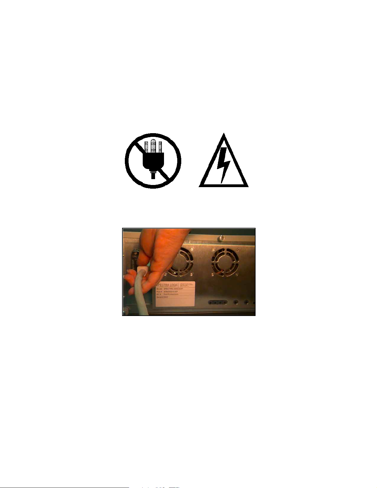
2. Remove the library’s AC power cord from the AC power outlet.
3. Carefully remove SCSI cable connections from the back of the library (Figure 1).
Figure 1 Remove SCSI cable.
8
Page 7
Spectra® 4000-10000 Unified Control Module (UCM) Board Replacement Guide
Removing the Library Cover
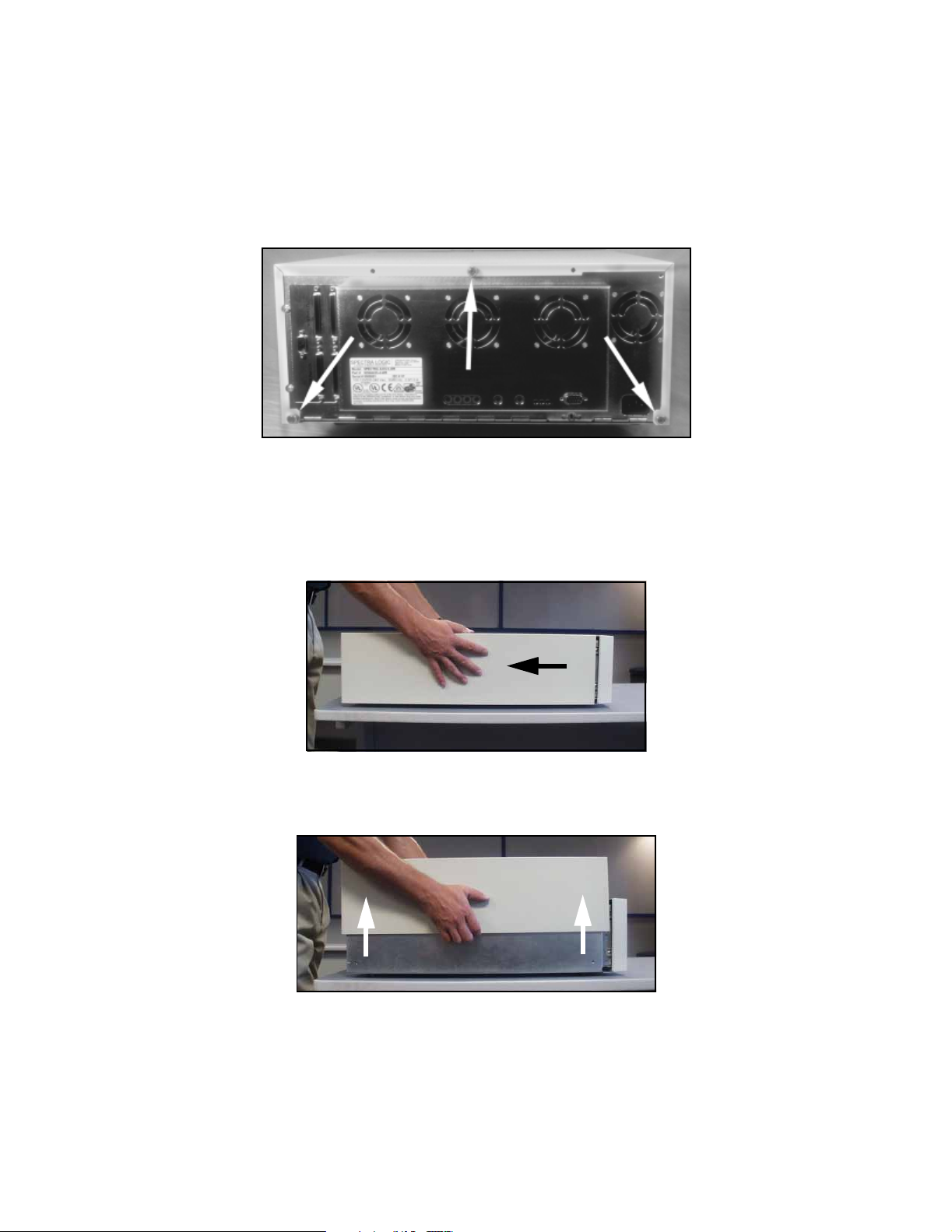
1. Using the flat head screwdriver, loosen the three thumbscrews (four screws if it is a
vertical unit) which secure the library’s cover (Figure 2).
Figure 2 Remove thumbscrews.
2. Slide the library cover back one half-inch away from the front panel to release the
cover’s side clips (Figure 3). Lift the cover off the library (Figure 4) and set it aside.
Figure 3 Slide the cover back.
Figure 4 Lift the cover.
9
Page 8

Spectra® 4000-10000 Unified Control Module (UCM) Board Replacement Guide
Removing the UCM Board in Spectra 4000-9000 Libraries
1. Locate the UCM board inside the library (Figure 5).
Caution: The UCM board is an Electrostatic Sensitive Device (ESD). Use
the static strap enclosed with the Spectra Logic UCM
replacement kit while handling assemblies inside the library.
Connect the static strap to your wrist and to the edge of the
.
library chassis to ensure a ground connection
Figure 5 UCM board location.
2. Disconnect the gray SCSI ribbon cables from the drive(s).
3. Release the connector eject latches and remove the grey SCSI ribbon cable from the
UCM board (Figure 6).
Figure 6 Connector eject latches.
10
Page 9

Spectra® 4000-10000 Unified Control Module (UCM) Board Replacement Guide
4. Using the #1 Phillips screwdriver, unscrew the two captive screws on the bottom of
the UCM bracket (Figure 7).
Figure 7 Remove the two captive screws on the
UCM bracket.
5. Remove the UCM assembly (board and bracket) by gently lifting it straight up and
out of the library.
6. Use a #1 Phillips screwdriver to remove the two screws attaching the UCM bracket
to the UCM board (Figure 8).
Note: Previous product releases use an earlier version of the UCM
bracket. Use the new bracket shipped with the replacement part.
Figure 8 Remove the screws attaching the UCM
bracket to the UCM board.
7. Remove the UCM board from the library.
11
Page 10

Spectra® 4000-10000 Unified Control Module (UCM) Board Replacement Guide
8. As soon as possible after removal, place the old UCM board into the anti-static bag
in which the new UCM board assembly was shipped.
Caution: Continue to keep the anti-static strap attached to your wrist and
to the library at all times while handling the UCM board.
9. Proceed to Replacing the UCM Board in Spectra 4000-9000 Libraries on page 17 to
continue the installation of the new UCM board.
12
Page 11

Spectra® 4000-10000 Unified Control Module (UCM) Board Replacement Guide
Removing the UCM Board in the Spectra 10000 Library
1. Use the #2 Phillips screwdriver to remove the Phillips screws holding the rear panel
of the library in place (Figure 9 and Figure 10). This allows the rear panel to hinge
open.
Note: If it is a rack mounted library, the lower screws on each side are
.
not installed
Figure 9 Screws holding the rear panel in place. Figure 10 Detach the rear panel.
2. Lower the top of the rear panel away from the library.
Note: The UCM Board is an Electrostatic Sensitive Device (ESD). Use the
static strap enclosed with the Spectra Logic UCM replacement kit
while handling assemblies inside the library. Connect the static
strap to your wrist, and then to the edge of the library chassis to
ensure a ground connection.
3. Disconnect the yellow SCSI ribbon cables from the drive(s).
13
Page 12

Spectra® 4000-10000 Unified Control Module (UCM) Board Replacement Guide
4. Use a #1 Phillips screwdriver to remove the captive screws which attach the UCM
bracket to the baseplate of the library (Figure 11).
Figure 11 Remove the two captive screws attaching the UCM
bracket to the baseplate of the library.
5. Disconnect the UCM board assembly by gently lifting it straight up. This will give
you access to the UCM bracket and cable straps.
6. Using a #1 Phillips screwdriver, remove the two screws which attach the UCM
bracket to the UCM board (Figure 12).
Figure 12 Remove the screws attaching the UCM
bracket to the UCM board.
7. Unplug the serial port cable (blue wires with white connector) from the UCM
board.
14
Page 13

Spectra® 4000-10000 Unified Control Module (UCM) Board Replacement Guide
8. Use your #1 Phillips screwdriver to remove the screws attaching each of the cable
straps to the UCM board (Figure 13).
Figure 13 Remove the cable straps.
9. Remove the two yellow SCSI ribbon cables from the UCM board (Figure 14).
Caution: Pull the connectors straight out and away from the UCM board.
Do not tilt or rock the connectors when removing them.
Figure 14 Disconnect the yellow SCSI ribbon cables
from the UCM board.
10. Remove the UCM board from the library.
11. As soon as possible after removal, place the old UCM board into the anti-static bag
in which the new UCM board assembly was shipped.
15
Page 14

Spectra® 4000-10000 Unified Control Module (UCM) Board Replacement Guide
Caution: Continue to keep the anti-static strap attached to your wrist and
to the library at all times while handling the UCM board.
12. Proceed to Replacing the UCM Board in the Spectra 10000 Library on page 19 to
continue the installation of the new UCM board.
16
Page 15

Spectra® 4000-10000 Unified Control Module (UCM) Board Replacement Guide
Replacing the UCM Board in Spectra 4000-9000 Libraries
Note: The UCM board is an Electrostatic Sensitive Device (ESD). Use the
static strap enclosed with the Spectra Logic UCM replacement kit
while handling assemblies inside the library. Connect the static
strap to your wrist and the library’s chassis to insure a ground.
1. Use a #1 Phillips screwdriver to replace the two screws attaching the UCM bracket
to the UCM board (Figure 15).
Note: Make sure to use the new UCM bracket shipped with the
replacement UCM board.
Figure 15 Replace the screws attaching the UCM
bracket to the UCM board.
2. Place the new UCM assembly (board and bracket) onto the library baseplate.
Carefully align the 96-pin connector of the UCM board with the 96-pin connector of
the library.
Caution: The connector should seat easily. Do not force the pins, as they
will bend and short circuit the library.
3. Align the two captive screws and holes with the mating parts of the drive baseplate
in the library. Using the #1 Phillips screwdriver, tighten the captive screws on the
UCM bracket (Figure 16).
17
Page 16

Spectra® 4000-10000 Unified Control Module (UCM) Board Replacement Guide
Note: For differential SCSI libraries, make sure that the differential card
bracket is aligned with the differential card. Proper alignment
ensures that the top edge of the SDC correctly positioned.
Figure 16 Replace the two captive screws on the UCM
bracket.
4. Insert the grey SCSI ribbon cable into the UCM Board (Figure 17). Make sure that
the connector eject latches are clipped over the top of the connector, securing the
cable in place.
Figure 17 Close the connector eject latches once the
SCSI connector has been inserted.
5. Proceed to Finish on page 22.
18
Page 17

Spectra® 4000-10000 Unified Control Module (UCM) Board Replacement Guide
Replacing the UCM Board in the Spectra 10000 Library
Note: Continue to use the static strap enclosed with the Spectra Logic
UCM replacement kit while handling assemblies inside the library.
Connect the static strap to your wrist, and then to the edge of the
library chassis to ensure a ground connection.
1. Using a #1 Phillips screwdriver, replace the two screws which attach the UCM
bracket to the UCM board (Figure 18).
Figure 18 Remove the screws attaching the UCM
bracket to the UCM board.
2. Connect the two yellow SCSI ribbon cables to the UCM board (Figure 19).
Figure 19 Connect the yellow SCSI connector ribbons
to the UCM board.
19
Page 18

Spectra® 4000-10000 Unified Control Module (UCM) Board Replacement Guide
3. Use a #1 Phillips screwdriver to tighten the screws attaching each of the cable
straps to the UCM board (Figure 20).
Figure 20 Replace the cable straps
4. Plug the serial port cable (blue wires with white connector) into the UCM board.
5. Place the new UCM assembly (board and bracket) onto the library baseplate.
Carefully align the 96-pin connector of the UCM board with the 96-pin connector of
the library.
Caution: Avoid bending the pins by pushing too hard. The connector
should seat easily. Do not force the pins.
6. Align the two captive screws and holes with the mating parts of the drive baseplate
in the library. Using the #1 Phillips screwdriver, tighten the captive screws on the
UCM bracket (Figure 21).
20
Page 19

Spectra® 4000-10000 Unified Control Module (UCM) Board Replacement Guide
Note: For differential SCSI libraries, also make sure that the differential
card bracket is aligned with the differential card.
Figure 21 Replace the two screws on the UCM bracket.
7. Connect the yellow SCSI ribbon cables to the drive(s).
8. Lift the top of the rear panel so that the panel connects with the sides of the unit.
9. Use the #2 Phillips screwdriver to replace the screws holding the rear panel of the
library in place (Figure 22 and Figure 23).
Figure 22 Attach the rear panel. Figure 23 Tighten the rear panel screws.
Note: If it is a rack mounted library, the lower screws on each side are
not installed.
21
Page 20

Spectra® 4000-10000 Unified Control Module (UCM) Board Replacement Guide
Finish
1. Replace the library cover and use the flat head screwdriver to tighten the three
thumbscrews (Figure 24). Note that the library cover will have four screws if it is a
vertical unit.
Figure 24 Replace the thumbscrews.
2. Slide the library cover forward so that it connects with the front panel and the
cover’s side clips.
3. Place the SCSI terminator on the SCSI-Out Connector, closest to the fans
(Figure 25).
Figure 25 Replace the SCSI cable.
4. Reconnect the library power cord.
5. Press the library’s power button on. Observe the library initialization. The Unit
Ready message should appear in the status box on the main screen.
6. Power on the server and confirm communication with the library and the drives.
Using one drive, check library inventory and verify media content.
22
Page 21

Spectra® 4000-10000 Unified Control Module (UCM) Board Replacement Guide
If you have difficulty
If you have difficulty with any part of this procedure, call Spectra Logic Technical
Support at (800) 227-4637, or at (303) 449-6444, extension 3175. Make sure to give the
support representative the model and serial number of your library, and say that you
are replacing the UCM board.
23
 Loading...