

Spectra Logic Spectra 64K, Spectra 12K Library, Spectra 64KLibrary, Spectra 12K Supplementary Manual
Page 1

Entry/Exit Port Slider
Replacement Guide
•Spectra® 12K Library
•Spectra
®
64K Library
Page 2

Notices
Spectra Logic® Corporation provides the unit “as is” without warranty of any kind, either
expressed or implied, including but not limited to the implied warranties of merchantability or
fitness for a particular purpose. In no event shall Spectra Logic be liable for any loss of profits,
loss of business, loss of use or data, interruption of business, or for indirect, special, incidental,
or consequential damages of any kind, even if Spectra Logic has been advised of the possibility of
such damages arising from any defect or error.
Information furnished in this manual is believed to be accurate and reliable. However, no responsibility
is assumed by Spectra Logic for its use. Due to continuing research and development, Spectra Logic may
revise this publication from time to time without notice, and reserves the right to change any product
specification at any time without notice.
Entry/Exit Port Slider Replacement Guide: Spectra 12K and Spectra 64K libraries
©
Copyright
2005 Spectra Logic Corporation. All rights reserved.
Spectra Logic Contact Information
Corporate Headquarters European Office
Address
Phone
Fax
Web Site
Spectra Logic Corporation
1700 N 55th Street
Boulder CO 80301
USA
(800) 833-1132 or (303) 449-6400
(303) 939-8844
http://www.SpectraLogic.com
Address
Phone
Fax
Spectra Logic Europe Limited
Magdalen Centre
Robert Robinson Avenue
Oxford Science Park
Oxford
UK OX44 7 RW
+44 (0) 870 112 2150
+44 (0) 870 112 2175
2
Page 3

Contents
Introduction ................................................................................................ 4
Prepare the Library and Host System ........................................................ 6
Remove the Robotic Rack Assembly .......................................................... 7
Remove the Spectra E/E Port Slider......................................................... 13
Replace the E/E Port Slider ...................................................................... 18
Replace the Robotic Rack Assembly ........................................................ 20
Prepare the Library for Tests.................................................................... 23
Tests .......................................................................................................... 24
Finish......................................................................................................... 27
Entry/Exit Port Slider Replacement Guide
3
Page 4
Entry/Exit Port Slider Replacement Guide
Introduction
About This Manual
This manual describes the procedure for replacing the entry/exit (E/E) port slider in
Spectra 12K and Spectra 64K libraries, and how to test the assembly after it has been
installed.
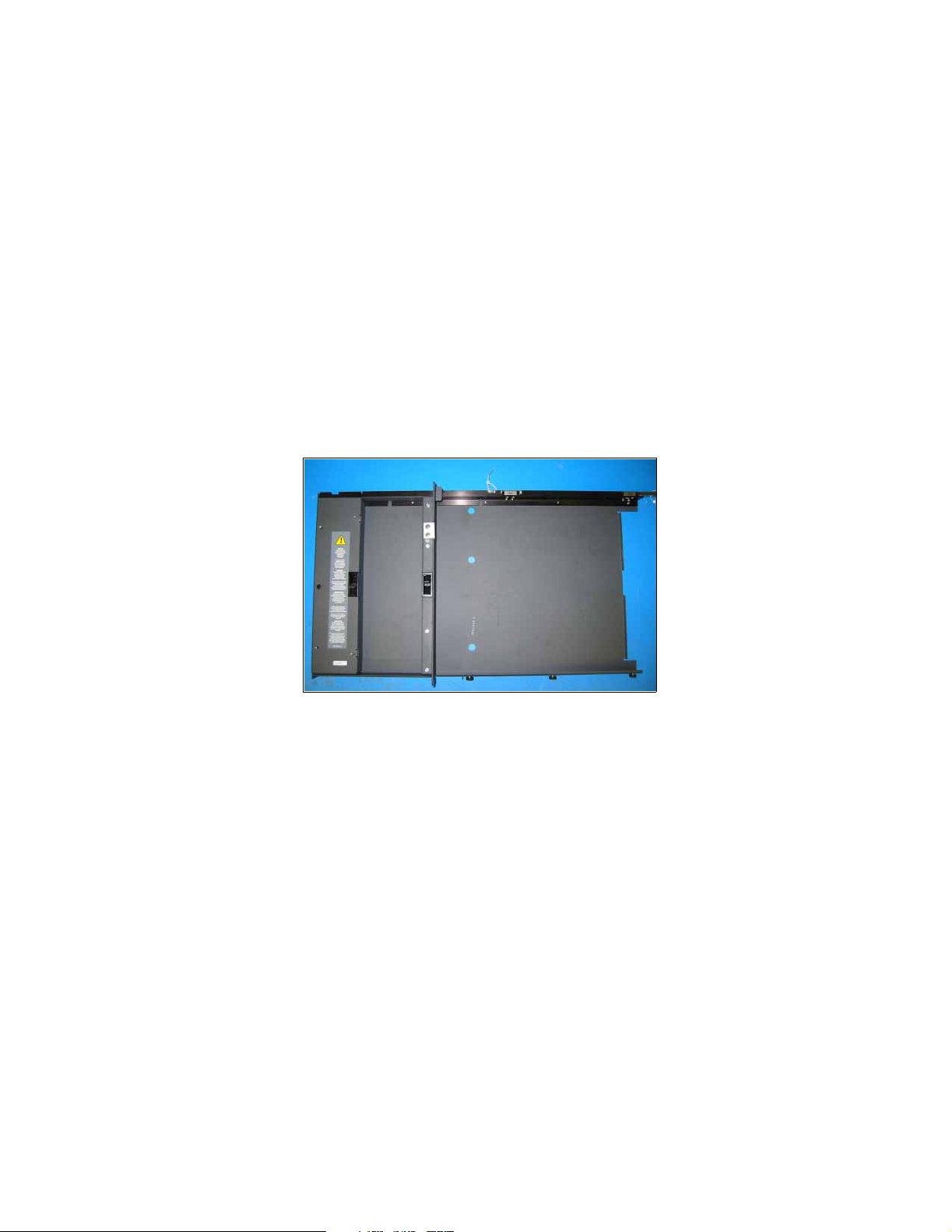
About the E/E Port Slider
The E/E port slider enables the E/E port to move in and out to load and unload tape
cartridges.
Figure 1 The E/E port slider.
Estimated Time Required
This procedure should take approximately two hours.
4
Page 5

Entry/Exit Port Slider Replacement Guide
Materials Required
You will need an E/E port slider assembly from Spectra Logic or an authorized reseller:
• E/E port slider assembly, P.N. 90919043 (top) or
• E/E port slider assembly, P.N. 90910044 (bottom)
You will also need the following tools:
• A #1 Phillips screwdriver
• A #2 Phillips screwdriver
• A 3/32-inch hex wrench
• A 2.5-mm hex wrench
• A small flat head screwdriver
• A large flat head screwdriver
• A flashlight
• The library door key
• The key to the rear door of the library (Spectra 64K libraries only)
5
Page 6
Entry/Exit Port Slider Replacement Guide
Prepare the Library and Host System
Shut down the library while keeping the host interface connected to the host system.
1. Disable any backup software that might try to access the library.
Warning: Electric shock inside the library can cause injury or death.
Disconnect AC power before opening the library door.
2. Turn off the power. The power switch is located at the rear of the library on the
lower left. (It is necessary to unlock and open the rear door of Spectra 64K
libraries.)
3. If necessary, move the library to a location where you have full access to the front
of the library.
Caution: The library is heavy. Get help when moving the library.
• The Spectra 12K library weighs approximately 175 lbs.
• The Spectra 64K library weighs approximately 880 lbs.
4. Remove the drives from the drive bay and set them aside in a safe place.
Note: It is not necessary to remove the media.
5. Use the library door key to unlock the front door of the library. You can now open
the door.
6
Page 7
Entry/Exit Port Slider Replacement Guide
Remove the Robotic Rack Assembly
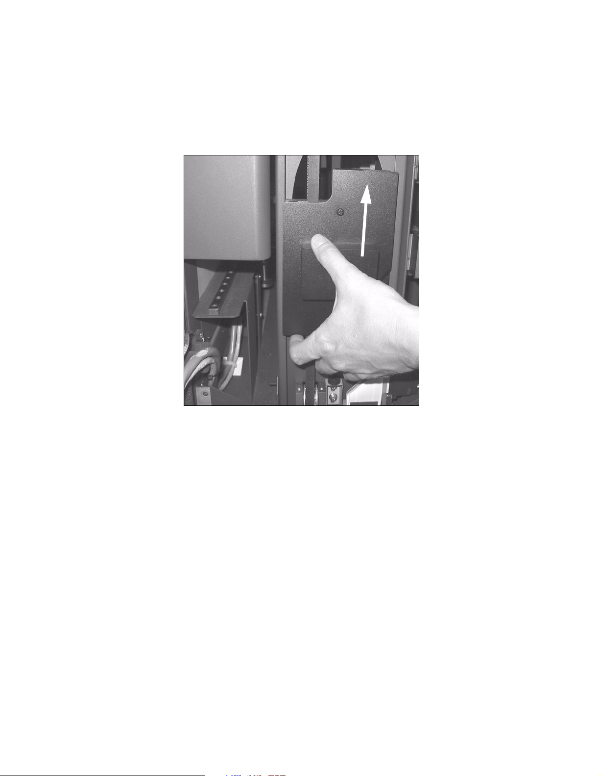
1. Lower the transport tray to bottom of the robotic rack by gently raising the counter
weight (Figure 2).
Figure 2 The robotic rack counter weight is raised.
7
Page 8
Entry/Exit Port Slider Replacement Guide
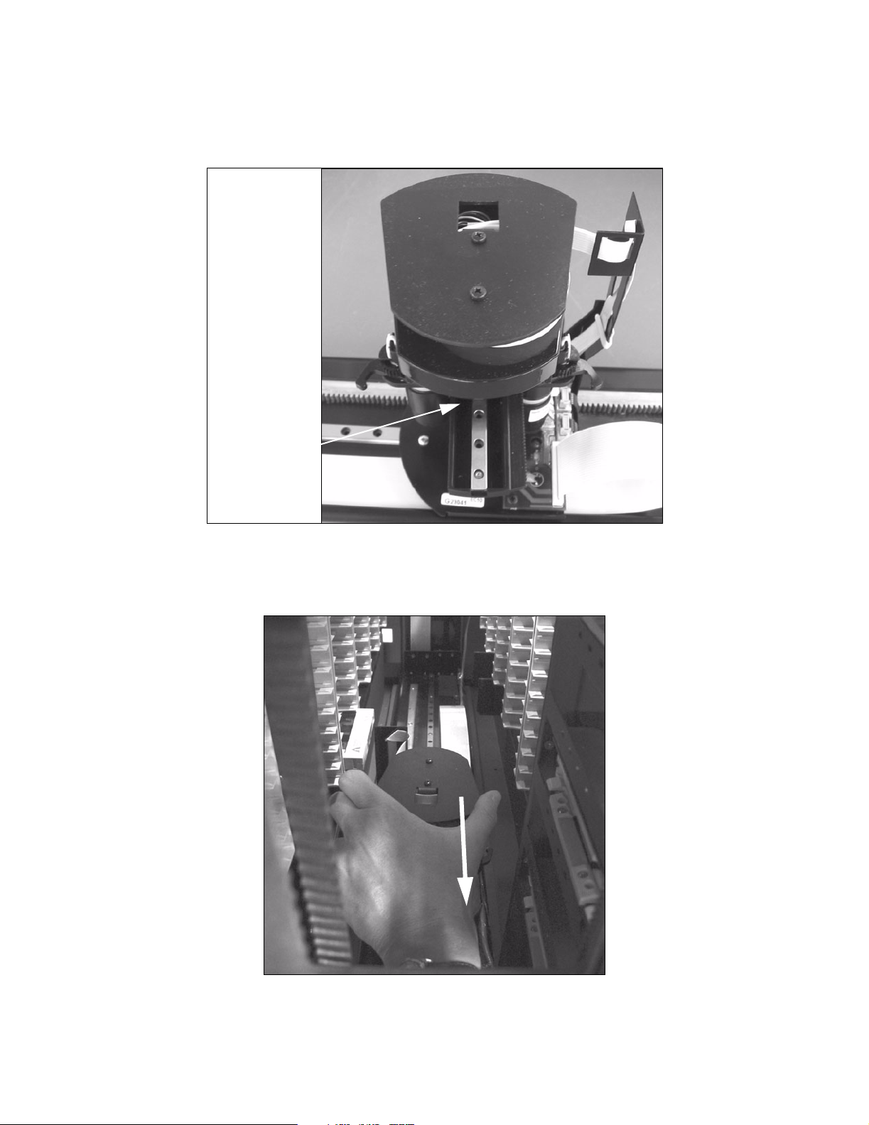
2. Rotate the picker so that the bar code scanner faces the rear of the library.
The location of the bar code scanner is shown in Figure 3.
Location of the
bar code scanner
Figure 3 The location of the bar code scanner.
3. Slide the picker along the transport tray to the front of the library (Figure 4).
Figure 4 The picker is slid to the front of the library.
8
Page 9
Entry/Exit Port Slider Replacement Guide
4. Look at the bottom of the library where the drives are located. If there is a hinge
connecting the left side of the drive slots to the back of the library (Figure 5),
proceed to Step 5.
If your library does not have a hinge (Figure 6), proceed to Step 6.
Figure 5 A library with a hinge. Figure 6 A library without a hinge.
5. Using the appropriate screwdriver, loosen the screws just enough to move the gate
out of the way from the robotic rack assembly (Figure 7).
• Some Spectra 12K libraries have three screws in the gate, and some units will
not have any screws in the gate.
• The Spectra 64K library has five screws in the gate.
Figure 7 The drive slot gate (Spectra 64K library shown).
9
Page 10

Entry/Exit Port Slider Replacement Guide
6. Unplug the 25-wire black connector at the bottom front of the robotic rack
assembly (Figure 8).
Figure 8 The 25-wire black connector (Spectra 12K library
shown).
7. Using the #2 Phillips screwdriver, loosen the screws that hold the robotic rack
assembly to the chassis: first the top three screws, then the bottom two (Figure 9).
Figure 9 The robotic rack with the screws circled
(Spectra 12K library shown). On a 64K library, the
screws will be in the same pattern.
10
Page 11

Entry/Exit Port Slider Replacement Guide
Note: Some Spectra 12K library models have only four screws attaching
the robotic rack to the chassis.
8. From the front of the library, carefully slide the robotic rack assembly outward
about six inches (15.24 cm) (Figure 10).
Figure 10 The robotic rack assembly is moved outward
(Spectra 12K library shown).
11
Page 12

Entry/Exit Port Slider Replacement Guide
9. From the side of the robotic rack assembly, carefully remove the robotic rack
assembly from the library (Figure 11 and Figure 12).
Figure 11 The robotic rack assembly being lifted out of the library
(Spectra 12K library shown).
Figure 12 The robotic rack assembly being
lifted out of the library (Spectra 64K library
shown).
10. Set the robotic rack assembly aside on a level surface away from traffic and the
library.
12
Page 13

Entry/Exit Port Slider Replacement Guide
Remove the Spectra E/E Port Slider
Note: The Spectra 64K library has one E/E port motor for each E/E port.
The motor for the top E/E port is located on the top of that E/E
port; the motor for the bottom E/E port is located on the bottom of
that E/E port. Only remove the E/E port motor that is attached to
the slider you are replacing.
1. Make sure the E/E port door is closed.
2. Disconnect the E/E port motor from both the power source and the motor cables
(Figure 13 and Figure 14).
Figure 13 The E/E port motor power source and motor
cables (Spectra 12K library shown).
Figure 14 The E/E port motor power source and motor
cables (Spectra 64K library shown).
13
Page 14

Entry/Exit Port Slider Replacement Guide
3. Using the appropriate screwdriver, remove the three screws holding the motor in
place (Figure 15 and Figure 16).
Note: Some libraries built before September 2000 may have four screws
attaching the motor to the E/E port. If your motor is installed with
four screws, call Spectra Logic Technical Support at (800) 227-4637
or (303) 449-0160. Inform the support representative that you are
installing an E/E port motor in a Spectra 12K or Spectra 64K
library, and your E/E port motor has four screws attaching it to the
E/E port. Spectra Logic Technical Support will provide you with
information to complete the motor removal.
Figure 15 The three E/E port motor screws (Spectra
12K library shown).
Figure 16 The three E/E port motor screws (Spectra
64K library shown).
4. Pull the motor either straight down or straight up as appropriate, and set the motor
aside.
14
Page 15

Entry/Exit Port Slider Replacement Guide
5. Pull the E/E port out and remove the cartridge pack (Figure 17).
Figure 17 Pull out E/E port and remove magazine pack.
6. Remove the four plastic magazines directly behind the E/E port, and remove the
five magazines directly above the E/E port, if you are replacing the top slider, or
directly below the E/E port, if you are replacing the bottom slider.
Note: Remove the magazine closest to the E/E port first. Make a note of
where each magazine location. They will need to go back in the
exact same location from where they were removed.
7. Note the location of the screws holes that indicate where the five screws that hold
the slider in place are located. You will need to remove these five screws in order
to remove the slider (Figure 18).
Figure 18 Location of screws.
15
Page 16

Entry/Exit Port Slider Replacement Guide
8. Remove the five screws using a 2.5 mm hex screwdriver. You will need to move the
slider back and forth to gain access to all the screws. You may also need to use the
holes within the slider to access some of the screws as shown in Figure 19.
Figure 19 Use the holes on the slider to access screws.
9. Using a flat-head screwdriver, remove the Stop that keeps the E/E port from sliding
all the way out (Figure 20), but do not remove the slider yet.
Figure 20 Remove the Stop.
Caution: Do not pull out the E/E port without holding on to the slider.
The slider is equipped with ball bearings that may fall out if the
slider and E/E port are removed separately.
16
Page 17

Entry/Exit Port Slider Replacement Guide
10. Carefully remove the E/E port and slider while holding on to both parts as
illustrated in Figure 21.
Figure 21 Carefully remove the E/E port and slider.
17
Page 18

Entry/Exit Port Slider Replacement Guide
Replace the E/E Port Slider
1. Remove the new E/E port slider from its packaging. Make sure to remove the
plastic clips holding the slider in place (Figure 22).
Figure 22 Remove slider from packaging and make sure to
remove the plastic clips (identified in picture).
2. Place the slider in carefully and replace the Stop.
Caution: Do not move the E/E port without holding on to the slider. The
slider is equipped with ball bearings that may fall out if the
slider and E/E port are removed separately.
3. Replace the five screws that hold the slider in place using the same method you
used to remove the original slider. Refer to Figure 18 for location of the five screws.
4. Replace the nine magazines you removed. Make sure that they are replaced in the
reverse order in which they were removed.
18
Page 19

5. Replace the E/E port motor.
Entry/Exit Port Slider Replacement Guide
Figure 23 The E/E port motor screws and the EC number
circled (Spectra 12K library shown).
Figure 24 The E/E port motor screws (Spectra 64K
library shown).
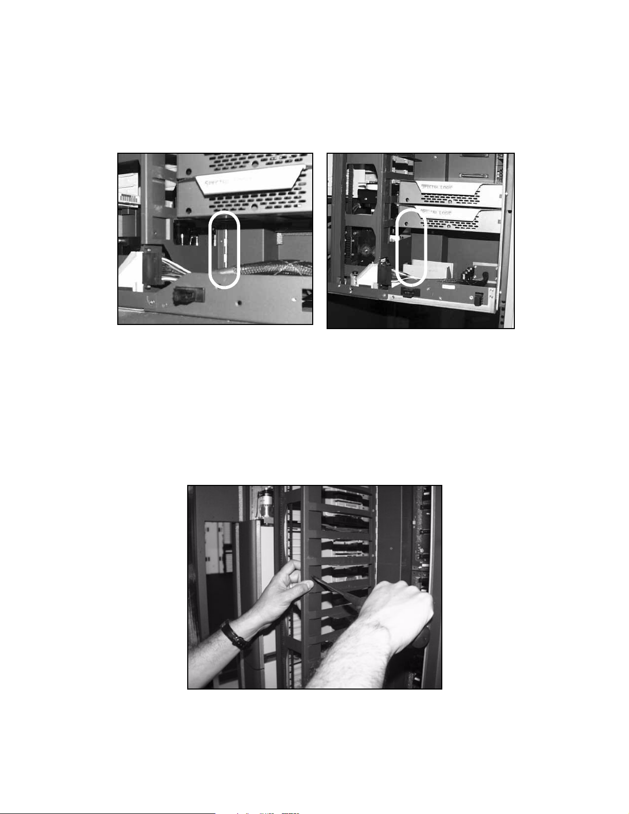
6. Connect the new E/E port motor power source and motor cables (Figure 25 and
Figure 26).
Figure 25 The E/E port motor power source and motor
cables (Spectra 12K library shown).
Figure 26 The E/E port motor power source and motor
cables (Spectra 64K library shown).
7. Gently move the E/E port door back and forth to ensure a smooth motion. If the
motion is not smooth, return to Step 1 and repeat the procedure.
19
Page 20

Entry/Exit Port Slider Replacement Guide
Replace the Robotic Rack Assembly
1. Carefully place the robotic rack assembly into the library (Figure 27 and Figure 28).
Figure 27 The robotic rack assembly being placed in the library (Spectra
12K library shown).
Figure 28 The robotic rack assembly being
placed in the library (Spectra 64K library shown).
20
Page 21

Entry/Exit Port Slider Replacement Guide
2. Carefully slide the robotic rack assembly all the way into the library (Figure 29).
Figure 29 The robotic rack assembly is moved all the way into
the library (Spectra 12K library shown).
3. Using the #2 Phillips screwdriver, tighten the screws that hold the robotic rack
assembly to the chassis: first the bottom, then the top (Figure 30).
Figure 30 The robotic rack with the screws
circled (Spectra 12K library shown).
21
Page 22

Entry/Exit Port Slider Replacement Guide
4. Plug in the 25-pin black connector at the bottom front of the robotic rack assembly
(Figure 31).
Figure 31 The 25-wire black connector (Spectra 12K
library shown).
Note: If you determined that you had a library without a hinge
connecting the left drive slots to the back of the library, proceed to
Prepare the Library for Tests on page 23. Otherwise, proceed to
Step 5.
5. Using the appropriate screwdriver, tighten the screws that hold the gate to the
robotic rack assembly (Figure 32).
Figure 32 The drive slot gate (Spectra 64K library
shown).
6. Proceed to Prepare the Library for Tests on page 23.
22
Page 23

Entry/Exit Port Slider Replacement Guide
Prepare the Library for Tests
1. Replace the drives in the drive bay.
2. Close and latch the library door.
3. If necessary, return the library to its normal operating location.
Caution: The library is heavy. Get help when moving the library.
• The Spectra 12K library weighs approximately 175 lbs.
• The Spectra 64K library weighs approximately 880 lbs.
4. Switch on AC power at the rear of the library. The library initializes and becomes
operational.
Caution: If the host computer or other equipment was restarted while the
library was out of service, you must exit all programs and shut
down all equipment before reconnecting the library.
5. Proceed to Install New Picker on page 24.
23
Page 24

Entry/Exit Port Slider Replacement Guide
Tests
Install New Picker
1. Make sure that you are logged in as a Super User.
2. Select Toolbars, then select Maintenance.
3. Select the Diagnostics icon; the Diagnostics screen displays.
4. From the Diagnostics screen, select Advanced.
5. From the Available Tests list, select Install New Picker (Figure 33).
Figure 33 The Diagnostics screen, showing the Available tests menu.
6. Select Prepare Test.
7. From the Diagnostics Configuration window, select Run Test (there are no
parameters for this test).
8. Once the picker has finished running the test, a message will appear reading
Install New Picker Succeeded; select OK to clear this message.
If this message does not appear, proceed as normal.
9. Proceed to Open the Entry/Exit Port on page 25.
24
Page 25

Entry/Exit Port Slider Replacement Guide
Open the Entry/Exit Port
1. Select Toolbars, then select General.
2. Select the Inventory icon in the upper left corner of the screen; the Library
Inventory screen displays.
3. Select Open/Close in the Entry/Exit Port menu (Figure 34).
Figure 34 The Library Inventory screen, showing the Entry/Exit Port menu.
4. The Confirm Open Entry/Exit Port window displays; select OK.
5. Insert any bar-coded tape into Slot 1 (the top slot) of the DCM in the E/E port.
6. Select Open/Close again to close the E/E port.
7. The Confirm Close Entry/Exit Port window displays; select OK.
8. Wait for the inventory sweep to complete, then verify that the bar code label is
correctly displayed in the Inventory screen.
9. Leave the tape in the E/E port.
10. Proceed to Picker-Slot Calibration on page 26.
25
Page 26

Entry/Exit Port Slider Replacement Guide
Picker-Slot Calibration
1. From the Available Tests list, select Picker Slot Calibration: Long Axis (as shown in
Figure 33 on page 24).
2. Select Prepare Test.
3. Select Run Test (there are no parameters for this test).
This test will calibrate the top and bottom location of each tape pack by loading
the tape in Slot 1 and Slot 15 of each data cartridge magazine.
4. Watch to see that each first and fifteenth slot loads correctly.
The tape will be returned to the E/E port when the test is completed.
Note: This test takes a long amount of time to complete. It could take up
to an hour in a fully-loaded Spectra 64K library.
5. Check the test results.
The test may indicate that retries were made, which is normal.
Caution: Make sure that there are no slots that fail to load. If a slot fails,
contact Spectra Logic Technical Support at (800) 227-4637 or at
(303) 449-0160.
6. Return to the Inventory screen.
7. Select Open/Close to open the E/E port.
8. Remove the tape from the library.
9. Select Open/Close to close the E/E port.
26
Page 27

Entry/Exit Port Slider Replacement Guide
Finish
This concludes the E/E port slider replacement procedure. Enable your backup
software to return the library to normal operations.
Next, be sure to follow the instructions under Package the Old E/E Port Slider Assembly
for Return to Spectra Logic on this page.
Package the Old E/E Port Slider Assembly for Return to Spectra Logic
You have five business days to return the exchanged product so that we may properly
credit your account. If the product is not received by Spectra Logic after five business
days, you will receive an invoice for the full purchase price.
1. Use the packaging you had set aside from the new slider to package and send the
old E/E port slider assembly back to Spectra Logic.
2. Secure the box closed with packaging tape and clearly label it for return to Spectra
Logic at the following address:
Spectra Logic Corporation
ATTN: {RMA Number}
Suite B
5571 Arapahoe Avenue
Boulder, CO 80303
Note: Make sure that you list the RMA number for this shipment in the
ATTN: line of the above address. If you do not know your RMA
number, call Spectra Logic Technical Support at (800) 227-4637 or
(303) 449-0160. All products shipped to Spectra Logic without an
RMA number will be returned to the customer after five days.
If You Have Difficulty
If you need assistance with this procedure, call Spectra Logic Technical Support at
(800) 227-4637 or (303) 449-0160. Inform the support representative that you are
installing an E/E port slider in a Spectra 12K, or Spectra 64K library.
27
 Loading...