

Page 1
NAStape
User Guide
Spectra Logic
P.N. 90930054 Revision A
Page 2

Notices
Notices
Except as expressly stated herein, Spectra Logic Corporation makes available its products and
associated documentation on an “as is” basis, without warranty of any kind, either expressed or
implied, including but not limited to the implied warranties or conditions of merchantability and
fitness for a particular purpose. In no event shall Spectra Logic be liable for any loss of profits,
loss of business, loss of use of data, interruption of business, or for indirect, special, incidental,
or consequential damages of any kind, even if Spectra Logic has been advised of the possibility of
such damages arising from any defect or error.
Information furnished in this manual is believed to be accurate and reliable. However, no responsibility
is assumed by Spectra Logic for its use. Because of continuing research and development, Spectra Logic
may revise this publication from time to time without notice, and reserves the right to change any
product specification at any time without notice.
Some products or services mentioned in this manual are provided by companies other than Spectra
Logic. Inquiries about one or more of these products or services should be sent directly to the company
in question. These brand or product names, registered trademarks, and trademarks are property of their
respective owners. These trademarks may be registered in this country, other countries, or both.
NAStape User Guide
Copyright © 2003 Spectra Logic Corporation. All rights reserved.
How to Contact Spectra Logic Corporation
United States Office European Office
Mailing Address Spectra Logic Corporation
1700 N 55th Street
Boulder CO 80301
USA
Phone (800) 833-1132 or (303) 449-6400 Phone +44 (0) 870 112 2150
Fax (303) 939-8844 Fax +44 (0) 870 112 2175
Mailing Address Spectra Logic Europe Limited
Magdalen Centre
Robert Robinson Avenue
Oxford Science Park
Oxford
UK OX44 7 RW
Technical Support (800) 227-4637 or (303) 449-0160
Web Site http://www.SpectraLogic.com
2
Page 3

Notices
License
You have acquired Spectra Logic® products that include software owned by or licensed by Spectra
Logic from one or more software licensors (Software Suppliers). Such software products, as well
as associated media, printed materials and “online” or electronic documentation (Software) are
protected by copyright laws and international copyright treaties, as well as other intellectual
property laws and treaties. The Software is licensed, not sold.
If you do not agree to this End User License Agreement (EULA), do not use the Spectra Logic product.
Instead, promptly contact Spectra Logic for instruction on return of the product for a refund. Any use of
the Software, including but not limited to use of the product, will constitute your agreement to this EULA
(or ratification of any previous consent).
GRANT OF LICENSE. The Software is licensed, not sold. This EULA grants you the following rights to the
Software:
• You may use the Software only on the Product with which it was sold.
• Not fault tolerant. The Software is not fault tolerant. Spectra Logic has independently determined how
to use the Software in the product, and suppliers have relied upon Spectra Logic to conduct sufficient
testing to determine that the Software is suitable for such use.
• No warranties for this software. The Software is provided “as is” and with all faults. The entire risk as
to satisfactory quality, performance, accuracy, and effort (including lack of negligence) is with you.
Also, there is no warranty against interference with your enjoyment of the Software or against
infringement. If you have received any warranties regarding Software, those warranties do not
originate from, and are not binding on, Software Suppliers.
• Note on Java support. The Software may contain support for programs written in Java. Java technology
is not fault tolerant and is not designed, manufactured, or intended for use of resale as online control
equipment in hazardous environments requiring fail-safe performance, such as the operation of
nuclear facilities, aircraft navigation or communication systems, air traffic control, direct life support
machines, or weapons systems, in which the failure of Java technology could lead directly to death,
personal injury, or severe physical or environmental damage.
• No liability for certain damages. Except as prohibited by law, Software Suppliers shall have no liability
for any indirect, special, consequential or incidental, damages arising from or in connection with the
use or performance of the Software. This limitation shall apply even if any remedy fails of its essential
purpose. In no event shall Software Suppliers, individually, be liable for any amount in excess of U. S.
two hundred fifty dollars (U.S. $250.00).
• Limitations on reverse engineering, decompilation, and disassemly. You may not reverse engineer,
decompile, or disassemble the Software, except and only to the extent that such activity is expressly
permitted by applicable law notwithstanding this limitation.
• Software transfer allowed with restrictions. You may permanently transfer rights under this EULA only
as part of a permanent sale or transfer of the Product, and only if the recipient agrees to this EULA. If
the Software is an upgrade, any transfer must also include all prior versions of the Software.
• Export restrictions. Export of the Software from the United States is regulated by Export
Administration Regulations (EAR, 15 CFR 730-744) of the U. S. Commerce Department, Bureau of
Export Administration. You agree to comply with the EAR in the export of re-export of the Software:
(i) to any country to which the U.S. has embargoed or restricted the export of goods or services,
which as of May 1999 include, but are not necessarily limited to Cuba, Iran, Iraq, Libya, North Korea,
Sudan, Syria, and the Federal Republic of Yugoslavia (including Serbia, but not Montenegro), or to any
national or any such country, wherever located, who intends to transit or transport the Software back
to such country; (ii) to any person or entity who you know or have reason to know will utilize the
Software or portion thereof in the design, development or production of nuclear, chemical, or
biological weapons; or (iii) to any person or entity who has been prohibited from participating in U.S.
export transactions by any federal agency of the U.S. government. You warrant and represent that
neither the BXA nor any other U.S. federal agency has suspended, revoked or denied your export
privileges. For additional information see: http://www.microsoft.com/exporting/.
3
Page 4

Warnings and Cautions
AC Power
Warning: Risk of electrical shock. To remove AC power from the NAStape
unit, unplug the power cord from the power inlet. There are no
user serviceable parts within the unit.
High Voltage
Warning: The NAStape unit contains high-voltage components that can
cause injury or death. Only qualified electricians should replace
or install high-voltage components.
Notices
Tapes
Caution: Use only the data cartridges approved for use with the drive
installed in the NAStape unit. Improper data cartridges can cause
damage to the NAStape, drive, and tape cartridges.
4
Page 5

Contents
Notices . . . . . . . . . . . . . . . . . . . . . . . . . . . . . . . . . . . . . . . . . . . . . . . . . . . . . . . . . 2
How to Contact Spectra Logic Corporation . . . . . . . . . . . . . . . . . . . . . . . . . . . . . . 2
License . . . . . . . . . . . . . . . . . . . . . . . . . . . . . . . . . . . . . . . . . . . . . . . . . . . . . . . . . 3
Warnings and Cautions . . . . . . . . . . . . . . . . . . . . . . . . . . . . . . . . . . . . . . . . . . . . . 4
Chapter 1. Introduction 9
About NAStape . . . . . . . . . . . . . . . . . . . . . . . . . . . . . . . . . . . . . . . . . . . . . . . . . . . 9
Flexible Connectivity . . . . . . . . . . . . . . . . . . . . . . . . . . . . . . . . . . . . . . . . . . . . . . . 9
About This Guide . . . . . . . . . . . . . . . . . . . . . . . . . . . . . . . . . . . . . . . . . . . . . . . . 12
Chapter 2. Installing NAStape 13
Preparing for Installation . . . . . . . . . . . . . . . . . . . . . . . . . . . . . . . . . . . . . . . . . . . 13
Unpacking the NAStape . . . . . . . . . . . . . . . . . . . . . . . . . . . . . . . . . . . . . . . . . . . . 14
Connecting the NAStape . . . . . . . . . . . . . . . . . . . . . . . . . . . . . . . . . . . . . . . . . . . . 16
Chapter 3. Using the HTTP Interface 17
Connecting to the HTTP Interface . . . . . . . . . . . . . . . . . . . . . . . . . . . . . . . . . . . . 17
Status . . . . . . . . . . . . . . . . . . . . . . . . . . . . . . . . . . . . . . . . . . . . . . . . . . . . . . . . . 19
Configuration . . . . . . . . . . . . . . . . . . . . . . . . . . . . . . . . . . . . . . . . . . . . . . . . . . . . 21
Maintenance . . . . . . . . . . . . . . . . . . . . . . . . . . . . . . . . . . . . . . . . . . . . . . . . . . . . 27
Security . . . . . . . . . . . . . . . . . . . . . . . . . . . . . . . . . . . . . . . . . . . . . . . . . . . . . . . . 28
Logout . . . . . . . . . . . . . . . . . . . . . . . . . . . . . . . . . . . . . . . . . . . . . . . . . . . . . . . . . 28
5
Page 6

Contents
Chapter 4. Using the Serial Port Interface 29
Serial Port Connection . . . . . . . . . . . . . . . . . . . . . . . . . . . . . . . . . . . . . . . . . . . . . 29
Password Configuration . . . . . . . . . . . . . . . . . . . . . . . . . . . . . . . . . . . . . . . . . . . . 32
Ethernet Configuration . . . . . . . . . . . . . . . . . . . . . . . . . . . . . . . . . . . . . . . . . . . . . 33
iSCSI . . . . . . . . . . . . . . . . . . . . . . . . . . . . . . . . . . . . . . . . . . . . . . . . . . . . . . . . . . 35
NDMP Setup . . . . . . . . . . . . . . . . . . . . . . . . . . . . . . . . . . . . . . . . . . . . . . . . . . . . 37
Enabling Options . . . . . . . . . . . . . . . . . . . . . . . . . . . . . . . . . . . . . . . . . . . . . . . . . 39
Jumbo Frames . . . . . . . . . . . . . . . . . . . . . . . . . . . . . . . . . . . . . . . . . . . . . . . . . . . 40
NDMP Backup Application Notes . . . . . . . . . . . . . . . . . . . . . . . . . . . . . . . . . . . . . 42
Chapter 5. Using the NAStape 43
Powering On and Off . . . . . . . . . . . . . . . . . . . . . . . . . . . . . . . . . . . . . . . . . . . . . . 43
Checking Connection Status . . . . . . . . . . . . . . . . . . . . . . . . . . . . . . . . . . . . . . . . . 43
Upgrading Firmware . . . . . . . . . . . . . . . . . . . . . . . . . . . . . . . . . . . . . . . . . . . . . . 44
Purchasing Media and Cleaning Cartridges . . . . . . . . . . . . . . . . . . . . . . . . . . . . . . 44
Chapter 6. NAStape 100 Tape Drives and Media 45
AIT Tape Drives . . . . . . . . . . . . . . . . . . . . . . . . . . . . . . . . . . . . . . . . . . . . . . . . . . 45
Chapter 7. NAStape 200 Tape Drives and Media 51
HP Ultrium Generation 1 Tape Drives . . . . . . . . . . . . . . . . . . . . . . . . . . . . . . . . . 52
IBM Ultrium Generation 2 Tape Drives . . . . . . . . . . . . . . . . . . . . . . . . . . . . . . . . . 56
Quantum SDLT 320 Tape Drives . . . . . . . . . . . . . . . . . . . . . . . . . . . . . . . . . . . . . 62
Chapter 8. Warranty and Repair 67
Limited Warranty . . . . . . . . . . . . . . . . . . . . . . . . . . . . . . . . . . . . . . . . . . . . . . . . . 67
Contacting Spectra Logic . . . . . . . . . . . . . . . . . . . . . . . . . . . . . . . . . . . . . . . . . . . 70
6
Page 7

Appendix A. Specifications 71
NAStape Power Requirements . . . . . . . . . . . . . . . . . . . . . . . . . . . . . . . . . . . . . . . 71
NAStape Safety Specifications . . . . . . . . . . . . . . . . . . . . . . . . . . . . . . . . . . . . . . . . 72
NAStape Environmental Specifications . . . . . . . . . . . . . . . . . . . . . . . . . . . . . . . . . 73
Sony AIT Specifications . . . . . . . . . . . . . . . . . . . . . . . . . . . . . . . . . . . . . . . . . . . . 74
HP LTO Ultrium Generation 1 Specifications . . . . . . . . . . . . . . . . . . . . . . . . . . . . 75
IBM LTO Ultrium Generation 2 Specifications . . . . . . . . . . . . . . . . . . . . . . . . . . . . 76
Quantum SDLT 320 Specifications . . . . . . . . . . . . . . . . . . . . . . . . . . . . . . . . . . . . 77
Appendix B. Regulatory and Safety Notices 79
Safety Agency Standards . . . . . . . . . . . . . . . . . . . . . . . . . . . . . . . . . . . . . . . . . . . 79
FCC Notice . . . . . . . . . . . . . . . . . . . . . . . . . . . . . . . . . . . . . . . . . . . . . . . . . . . . . 79
Japan VCCI-A . . . . . . . . . . . . . . . . . . . . . . . . . . . . . . . . . . . . . . . . . . . . . . . . . . . 80
EU Declaration of Conformity . . . . . . . . . . . . . . . . . . . . . . . . . . . . . . . . . . . . . . . . 81
Index 83
7
Page 8

8
Page 9

1 Introduction
About NAStape®
The NAStape provides an interconnection that is easy to install, configure, and use.
Designed specifically for the needs of network-attached storage (NAS) environments,
the NAStape brings Ethernet (iSCSI) and NDMP connectivity to legacy SCSI tape drive
devices. It provides serial and Ethernet in-band management ports, and an easy-to-use
Web-based configuration utility. The NAStape 100 and NAStape 200 support only
single-ended or LVD SCSI tape drives.
Note: Neither NAStape 100 nor NAStape 200 will support high-voltage
differential (HVD) tape drives.
The NAStape 100 supports a single Sony AIT-2 drive or Sony AIT-3 drive, and the
NAStape 200 supports a single Quantum SDLT 320, HP LTO Ultrium, or IBM LTO-2
tape drive. Both the NAStape 100 and NAStape 200 provide the interconnectivity
required in today’s NAS environments.
Flexible Connectivity
Spectra Logic’s flexible connectivity uses an innovative approach to sharing tape
backup resources among hosts. It enables the NAStape to be connected to a storage
network using one of several protocols, including Network Data Management Protocol
(NDMP) and Internet SCSI (iSCSI).
The NAStape comes with a Gigabit Ethernet interface. It supports 10BaseT, 100BaseT,
and 1000BaseT network connectivity, and comes with iSCSI enabled (or you can
purchase the NDMP option).
The NAStape incorporates an in-band HTTP-based application for device configuration
and management.
9
Page 10

Chapter 1. Introduction
iSCSI
The iSCSI standard, as ratified by the Internet Engineering Task Force (IETF) in
February 2003, provides a guideline for supporting the various capabilities of the iSCSI
protocol. There are features that are specified by the governing organization to be
mandatory and other features that can be optional. Spectra Logic supports all required
features of the iSCSI specification for target devices.
Note: The required features for iSCSI could be changed by the iSCSI
governing organization.
NDMP
NDMP is an option that can be purchased and enabled for the i1000 (see the NDMP
product directory at www.ndmp.org/products/index.shtml
applications and NAS devices). The i1000 supports Version 2 and Version 3 of NDMP
(see www.ndmp.org
for more information about NDMP protocol versions).
for supported backup
Sharing Tape Devices
Both iSCSI and NDMP allow a set of tape resources to be shared between multiple
hosts.
Caution: Care must be taken to ensure that multiple requests are not
being sent to the same tape drive at the same time.
With NDMP, there is typically a backup application server that manages access to the
tape drives. Even though multiple NAS devices can access the tape device, these
requests are routed through a single backup server that is responsible for managing
access to the drives. As long as the devices and NAS clients are configured properly in
the software, resource contention is eliminated. Access to NDMP functionality is also
password protected—any host wishing to utilize the NAStape must authenticate
themselves with the correct username and password (set up in the backup software).
With iSCSI, there may be many backup applications on many hosts, all responsible for
managing their own access to the tape drives, and as the NAStape looks like a locally
attached resource to each configured host, each host has no idea that other hosts also
have access.
There are several ways to manage resource contention with iSCSI. First, the NAStape
drive will only be visible to hosts where the individual devices are installed. Next,
devices that are shared among multiple servers can be locked during use by a backup
10
Page 11

Chapter 1. Introduction
application utilizing the SCSI Reserve and Release commands. When a device has been
locked, no other host can gain access to the drive until it is unlocked.
In any case, if multiple hosts will be accessing the NAStape, some access management
scheme must be implemented to prevent stored data written by one host from being
overwritten by another. Check with your software application for this compatibility.
11
Page 12

Chapter 1. Introduction
About This Guide
This guide is written for NAStape owners, and reviews NAStape installation and use.
Conventions Used
This guide uses special conventions to highlight notes, cautions, and warnings.
Note: Read Notes for additional information or suggestions about the
topic or procedure being discussed.
Caution: Read Cautions to learn ways to avoid damaging NAStape, tape
drives or other equipment.
Warning: Read Warnings to learn ways to avoid personal injury.
Equipment Markings
CE Listed Equipment
This symbol advises the operator that the marked equipment has been
rated as a CE approved appliance.
12
Page 13

2 Installing NAStape
This chapter covers the following information:
• Preparing for Installation
• Unpacking the NAStape
• Connecting the NAStape
Preparing for Installation
Before you install a NAStape unit, complete these steps:
• Identify the host that is to be associated with the unit, and its operating system.
• Determine how the NAStape is to be used with your backup software.
• If you will be using the Web-based configuration and management tools, you may
need to obtain an available IP address for the NAStape. NAStape comes with DHCP
and WINS enabled, however you will need to manually configure the IP address if
there is no DHCP server on the local network segment.
Proper Installation Environment
When planning the NAStape installation, note that the unit, the drive, and media must
be maintained in a controlled environment. Environmental extremes and large
quantities of airborne particulates can cause erratic operation of any peripheral,
including the NAStape unit. See Appendix A. Specifications for information on NAStape
operating specifications and tape drive operating specifications.
13
Page 14
Chapter 2. Installing NAStape
Unpacking the NAStape
Before unpacking the NAStape, note that it is shipped with the following items:
• Quick Setup Guide
• CD-ROM, including firmware and User Guide (this guide)
• One media cartridge and one cleaning cartridge
(only for the NAStape 200 configured with and SDLT 320 drive)
•AC power cord
• Serial cable
Note: There is no Ethernet cable included.
Removing the NAStape from Its Packaging
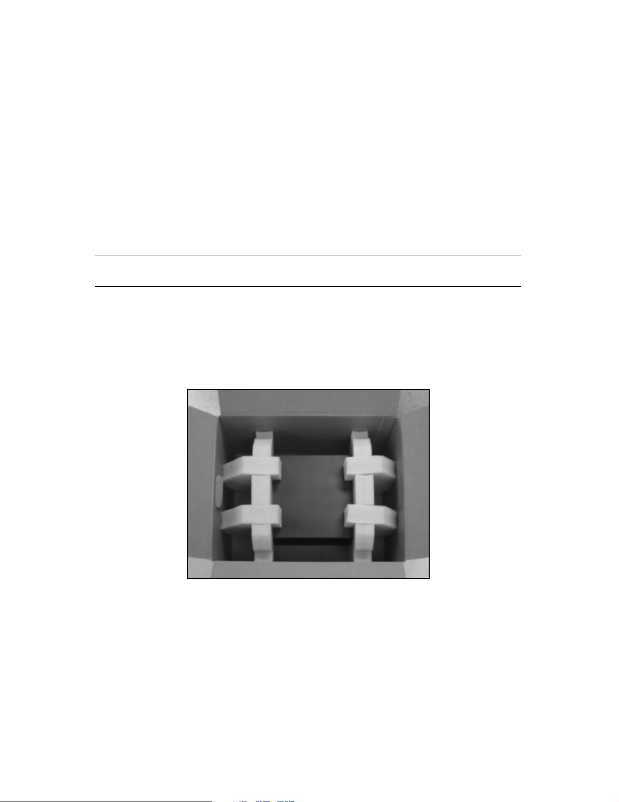
To unpack the NAStape from its box, follow these steps.
1. Remove the NAStape unit and its foam protectors from the box (Figure 2-1).
Figure 2-1 The NAStape with its foam supports inside the box.
14
Page 15
Chapter 2. Installing NAStape
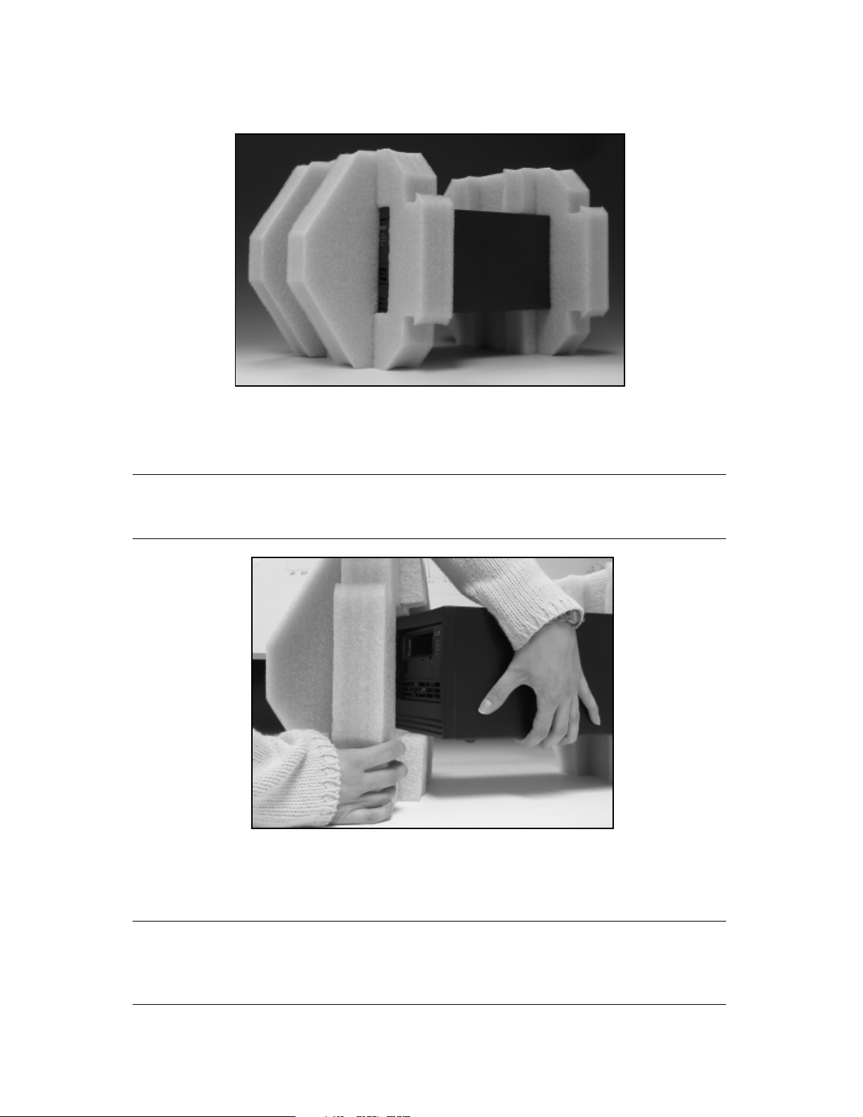
2. Set the protected NAStape on a clean, stable work surface (Figure 2-2).
Figure 2-2 The NAStape in its foam supports.
3. Remove the foam from each end of the NAStape, one end at a time.
Caution: Be sure to support the first end before removing the foam from
the second end.
Figure 2-3 Remove the foam from the NAStape.
4. Move the NAStape to the installation site when you are ready to connect it.
Note: Keep NAStape’s packing materials in a safe place for moving or
shipping the NAStape in the future. Any damage caused to
NAStape due to improper packaging may void its warranty.
15
Page 16

Chapter 2. Installing NAStape
Connecting the NAStape
Follow these instructions to connect the NAStape unit.
1. Plug in the power cord.
2. Turn on the NAStape unit.
Note: The NAStape will make a high-pitched noise upon start up. This is
normal behavior for the low-voltage sensor in the unit.
There are two interfaces available to configure and set up your options: HTTP and
serial port. Select the appropriate method based on your environment.
DHCP Environment To use the HTTP configuration application, proceed to Chapter 3.
Using the HTTP Interface.
Static IP Environment To use the serial port interface, or if you’re unable to use the
HTTP interface, proceed to Chapter 4. Using the Serial Port Interface.
16
Page 17

3 Using the HTTP Interface
This chapter describes how to configure your NAStape using an HTTP interface. This
includes Connecting to the HTTP Interface, as well as using the following screens
within the interface:
• Status
• Configuration
• Maintenance
• Security
• Logout
Connecting to the HTTP Interface
Note: The Ethernet port is assigned a default hostname of
SL<serial number>-0, where <serial number> is the serial number
of the NAStape (located on the rear panel of the NAStape). This
hostname may be changed to avoid duplicate hostnames.
Note: If you are having trouble bringing up the Web page with Internet
Explorer, be sure to check your HTTP proxy settings. To change
your settings:
i. Go to Tools > Internet Options > Connections > LAN Settings >
Advanced.
ii. Add the IP address or hostname of the NAStape to the
Exceptions list.
1. Connect the NAStape to your network; DHCP can assign the IP address, subnet
mask, iSNS, gateway information, and WINS if configured to do so.
If the DHCP service is only supplying the IP address, you can fill in the rest of
the information through the HTTP or serial interface.
17
Page 18
Chapter 3. Using the HTTP Interface
2. Once a network connection is established, open an internet browser and enter
the IP address or hostname for the NAStape.
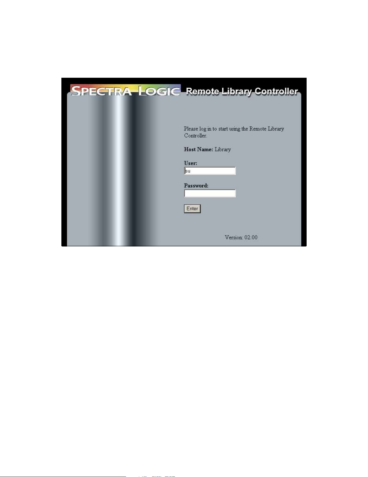
3. The following page will open:
Figure 3-1 The Login screen.
4. Enter the default User of SU and select Enter. Do not enter any password.
If this is the first time using your NAStape, the default super user setting is
username SU with no password.
How to Proceed
If you would like to view the NAStape status, go to Status on page 19.
If you would like to enable NDMP, go to Options on page 21.
If you would like to configure NAStape protocols, go to Protocols on page 24.
If you would like to add or edit users, go to Security on page 28.
18
Page 19
Chapter 3. Using the HTTP Interface
Status
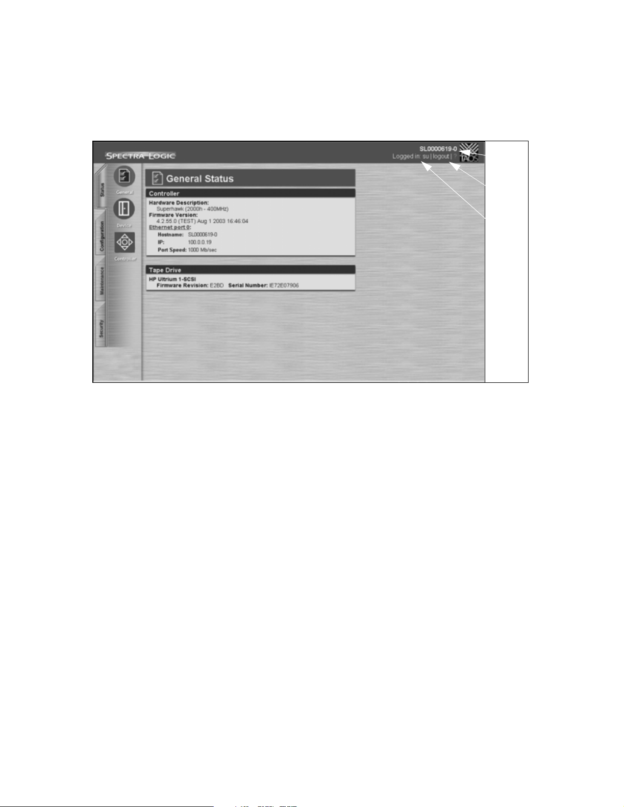
The General Status screen will be the first screen to display after you have logged in.
Host
name
Click to
log out
Current
user
Figure 3-2 The General Status screen.
Use the tabs on the left to navigate sections; use the large icons to navigate screens
within that section.
19
Page 20

Chapter 3. Using the HTTP Interface
General Status
The General Status screen details information on the following:
Controller
This section of the screen details information specific to the NAStape controller.
Firmware Version Identifies the current controller firmware version and the date it was
built.
Ethernet Port Identifies the Hostname, the IP address and the Ethernet port speed. Click
on Ethernet Port to configure. For more information on configuring the ethernet
interface, go to Ethernet on page 22.
Tape Drive
This section of the screen identifies the tape drive type, the current tape drive firmware
version, and the tape drive serial number.
Device
This section details information about the NAStape and its drive.
Note: You cannot configure from this screen; it is informational only.
Controller
This section details information about the NAStape interface.
Note: You cannot configure from this screen; it is informational only.
20
Page 21
Chapter 3. Using the HTTP Interface
Configuration
Options
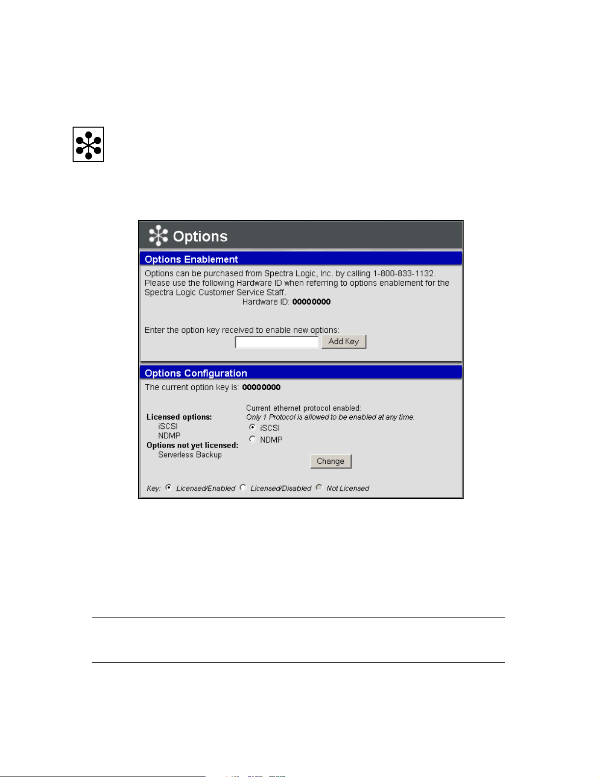
The Options screen offers choices for enabling and configuring the NAStape’s available
options.
Figure 3-3 The Options screen.
Options Enablement
This section identifies the hardware ID that you will need to be able to receive an
option key. Once you have an option key, you can enter it in this section. Enter the
number and select Add Key. You can enable iSCSI and NDMP using this screen.
Caution: Do not enter or save invalid activation keys. This could disable
existing options.
21
Page 22
Chapter 3. Using the HTTP Interface
Options Configuration
This section lists the available licensed options and options not yet licensed. You can
select which licensed option you would like enabled here. Once you have made your
selection, select Change.
Not Licensed This option is not available until purchased and activated with a key code.
Licensed/Disabled The option has been purchased but is currently inactive.
Licensed/Enabled The option is currently licensed and active.
Note: Ethernet storage devices may have only one protocol active at any
given time. Enabling one Ethernet protocol will automatically
disable all other Ethernet protocols that are currently licensed.
Interface
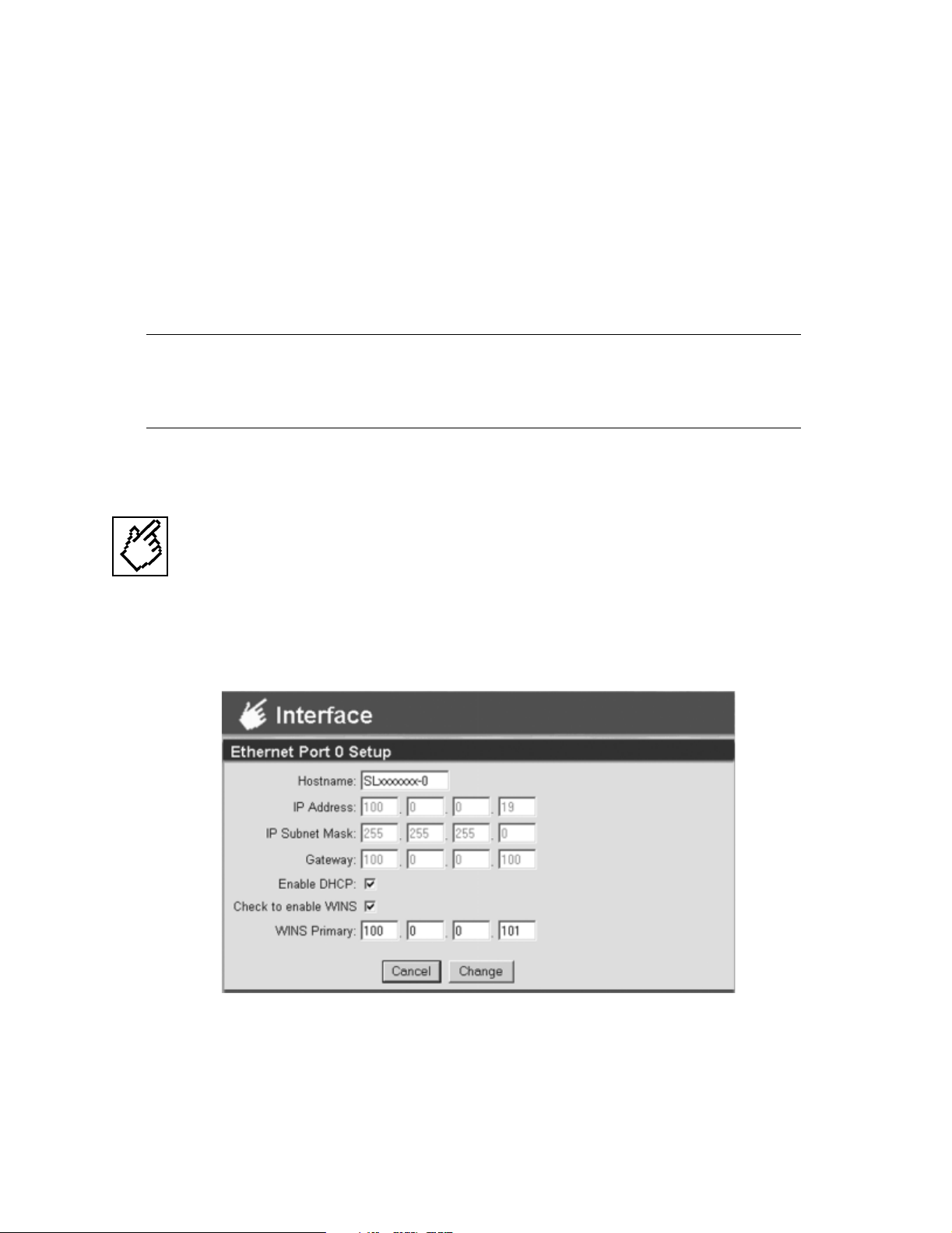
You can configure the Ethernet interface using this screen.
Ethernet
Figure 3-4 Ethernet Port Setup screen.
22
Page 23

Chapter 3. Using the HTTP Interface
The Ethernet Port Setup screen allows you to configure the Hostname, IP Address, IP
Subnet Mask, and Gateway for your Ethernet interface. You can also enable DHCP and
WINS in this screen. Select Change to have the configuration saved.
Hostname: The name for the IP interface. This is used by DHCP, DNS, and other
communications for name resolution. The hostname should be less than 12 characters
to support DHCP and DNS naming conventions.
IP Address: Static IP address. This field is not available while in DHCP mode.
IP Subnet Mask: IP network mask (standard IP parameter).
Gateway: Gateway address (standard IP parameter).
Enable DHCP: Select to enable DHCP. If DHCP is disabled, you must provide a static IP
address.
Note: If DHCP is used, the IP address should never expire. The DHCP
servers should be configured to supply an IP address that will
never change.
Enable WINS: Select to enable WINS.
WINS Primary: IP address for the primary WINS server.
Change: Select Change to save parameters.
23
Page 24
Chapter 3. Using the HTTP Interface
Protocols
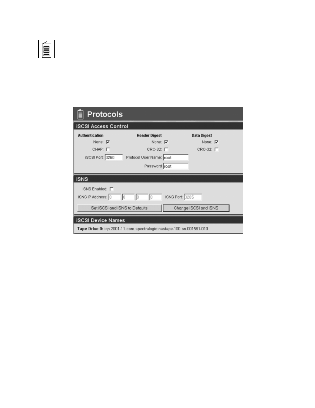
The Protocols screen will display the protocol page for whichever type of licensed
protocol you have enabled (iSCSI, or NDMP).
iSCSI
Figure 3-5 The Protocols screen for iSCSI.
The following parameters should be configured to match the capabilities of the iSCSI
initiators that are connecting to the NAStape. Select Change iSCSI and iSNS to save the
information.
iSCSI Access Control
iSCSI Port The default iSCSI listen port number is 3260. This is the IANA assigned port
for iSCSI and should not be modified under normal conditions.
Authentication Select None if you do not wish to have an authentication method enabled.
Select Challenge Handshake Authentication Protocol (CHAP) authentication which
uses MD5 encrypted passwords and usernames.
Header and Data Digest Select None if you do not wish to have a header or data digest.
Cyclic Redundancy Check 32 (CRC-32) detects data transmission errors.
24
Page 25

Chapter 3. Using the HTTP Interface
Note: Enabling CRC will have an impact on performance.
Protocol User Name Set a User Name for iSCSI.
Password Set a Password for iSCSI.
iSNS
iSNS Enabled Check this box to enable iSNS. When iSNS is enabled it is necessary to
specify the IP address of the iSNS server.
iSNS IP Address Enter the IP address of the iSNS server. This must be a valid server IP
whenever iSNS is enabled.
iSNS Port The default port (3205) is assigned by IANA and should not be modified
under normal conditions.
Set iSCSI and iSNS to Defaults Select if you want the default parameters reset.
Change iSCSI and ISNS Select if you want to save the parameters.
iSCSI Device Names
Tape Drive: This is the tape drive device name.
25
Page 26
Chapter 3. Using the HTTP Interface
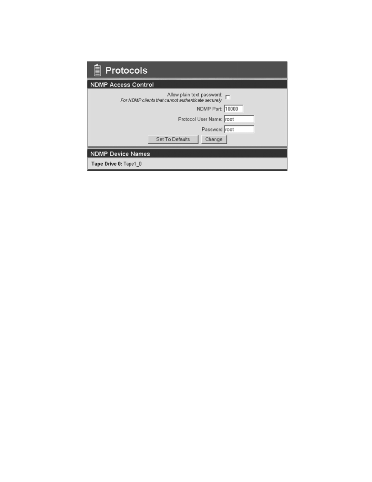
NDMP
Figure 3-6 The NDMP Access Control screen.
Configure the NDMP port, and add a username and password. You can also select to
allow plain text passwords. Select Change to save the information. The NDMP Device
Names are also listed.
26
Page 27
Chapter 3. Using the HTTP Interface
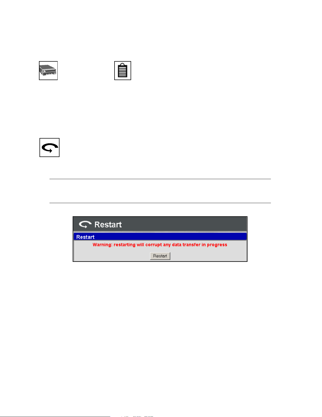
Maintenance
Drive Info Controller Info
Selecting either of these icons will give you detailed information about that specific
device. Use these icons to assist in troubleshooting your device. To view the
information, select the appropriate icon for the device type, select the specific device
from the drop-down menu, and then select GO.
Restart
Selecting the Restart icon will save all configured parameters and restart the NAStape.
Caution: Make sure that there are no data transfers in progress when you
restart the NAStape.
Figure 3-7 The Restart Warning screen.
27
Page 28

Security
Users
Chapter 3. Using the HTTP Interface
Figure 3-8 The Security Users screen.
If this is the first time using your NAStape, the default super user setting is username
SU with no password.
Add User Select a Name, Password, and Security level, and then select Add User.
Edit User Select a current user to edit, update their information, and then select Change.
Delete User Select the user to be deleted, and the select Delete.
Note: You cannot delete the last user with super user permissions.
Logout
To log out, simply select the Logout link located in the upper right-hand corner of the
HTTP interface.
28
Page 29

4 Using the Serial Port Interface
Serial Port Connection
1. Connect a serial cable to the NAStape (the diagnostic port located by the serial
number tag) with a serial port terminal emulation application (like
HyperTerminal) running on a host computer.
2. The serial port settings should be set as follows:
Figure 4-1 Serial port settings.
3. After making sure the serial port settings are correct, select OK.
29
Page 30

Chapter 4. Using the Serial Port Interface
4. Select Enter in HyperTerminal; the TAOS Configuration Menu will display
(Figure 4-2):
Figure 4-2 The TAOS configuration menu.
[1] Management Account: Select to set or change the user name and password for
the serial port configuration menu.
[2] Fibre configuration: Not available in NAStape.
[3] Ethernet configuration: Select to configure the Ethernet settings.
[4] TAOS ITP: Not available in NAStape.
[5] TAOS NDMP: Select to configure the NDMP settings.
[6] TAOS iSCSI: Select to set configure the iSCSI settings.
[7] Enable Device options: Not available in NAStape.
[8] Options Enablement: Select to activate licenses and enable options.
[9] Save changes: Select to save changes. All changes must be saved before they
can take effect.
[a] Discard changes: Select to cancel any changes.
[b] Reboot: Select to reboot the NAStape.
30
Page 31

Chapter 4. Using the Serial Port Interface
How to Proceed
If you need create or reset a password, go to Password Configuration on page 32.
If you would like to configure your Ethernet ports, iSCSI, or NDMP, go to Ethernet
Configuration on page 33.
If you need to enable NDMP, go to Enabling Options on page 39.
31
Page 32
Chapter 4. Using the Serial Port Interface
Password Configuration
As shipped, the serial port configuration menu is not password protected. To prevent
unauthorized changing of NAStape configuration settings, you can enable a password.
1. Select 1 from the TAOS Configuration Menu.
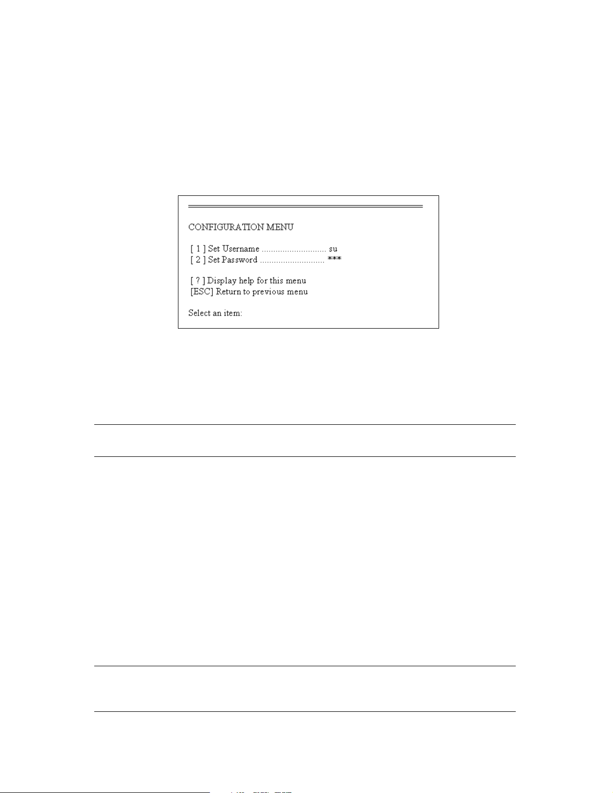
2. The Password Configuration Menu is displayed (Figure 4-3).
Figure 4-3 The Password Configuration Menu.
[1] Set Username: Select to set or change the username.
[2] Set Password: Select to set or change the password. If changing the password,
you will be prompted to enter your password, then to re-enter it.
Note: This password is also used to validate firmware updates using FTP.
[?] Help: Displays help for this menu.
[ESC] Return to previous menu: Returns you to the TAOS Configuration Menu.
3. Select 1 to set a configuration username, then select 2 to set a configuration
password.
4. Press Esc to return to the TAOS Configuration Menu.
There will be an asterisk (*) next to the menu option, indicating that an unsaved
change has been made.
5. Select 9 from the TAOS Configuration Menu to save the changes.
6. Select y when prompted to reboot.
Note: You must reboot the NAStape in order for the username and
password changes to take effect.
32
Page 33
Chapter 4. Using the Serial Port Interface
Ethernet Configuration
The NAStape is shipped with DHCP enabled and a preset hostname based on the serial
number of the board. The Ethernet port is assigned a default hostname of
SL-0000<serial number>-0, where <serial number> is the serial number of the NAStape,
located on the rear panel of the NAStape. This hostname may be changed using the
Ethernet Configuration Menu.
Before attaching the NAStape to your network, these values should be set as
appropriate for your site.
1. To launch the Ethernet Configuration Menu, select 3 from the TAOS
Configuration Menu.
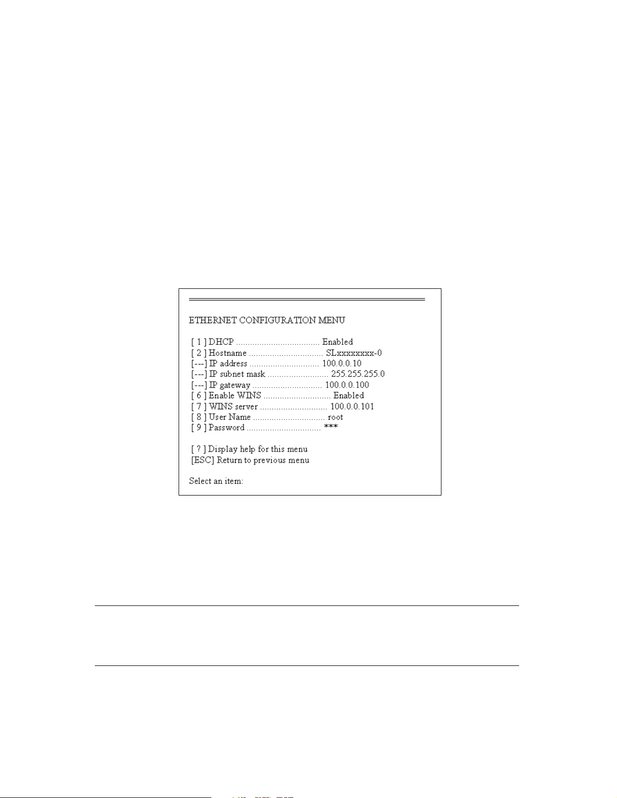
The Ethernet Configuration Menu appears (Figure 4-4).
Figure 4-4 The Ethernet Configuration Menu.
2. To configure the Ethernet port, use the following options:
[1] DHCP: Select to enable DHCP. When DHCP is enabled, the hostname is used as
part of the system identification. If DHCP is disabled, you must provide a static
IP address.
Note: If DHCP is used, the IP address should never expire. The DHCP
servers should be configured to supply an IP address that will
never change.
33
Page 34

Chapter 4. Using the Serial Port Interface
[2] Hostname: The name for the IP interface. This is used by DHCP, DNS and other
communications for name resolution. The hostname should be less than 12
characters to support DHCP and DNS naming conventions.
[3] IP address: Static IP address. This field is not available while in DHCP mode.
[4] IP subnet mask: IP network mask (standard IP parameter). This field is not
available while in DHCP mode.
[5] IP gateway: Gateway address (standard IP parameter). This field is not
available while in DHCP mode.
[6] Enable WINS: Typing 6 will toggle WINS on and off.
[7] WINS server: When WINS is enabled, it is necessary to specify the address of
the WINS server.
[8] User Name: This username parameter is used for authentication for iSCSI and
NDMP protocols. Type 8, then type a new username.
[9] Password: Select or change the password. If changing the password, you will
be prompted to enter your password then to re-enter it.
[?] Help: Displays help for this menu.
[ESC] Return to previous menu: Returns you to the TAOS Configuration Menu.
3. Press Esc to return to the TAOS Configuration Menu.
There will be an asterisk (*) next to the menu option, indicating that an unsaved
change has been made.
4. Select 9 to save the changes.
5. Select y when prompted to reboot.
Note: You must reboot the NAStape in order for the new Ethernet
parameters to take effect.
Procedure Notes
You can continue to configure your NAStape using the serial port, or you can use the
Web interface, which is more user–friendly. Use the information from the Ethernet
Configuration screen to assist with attaching the NAStape to an IP connection. To use
the Web interface, go to Chapter 3. Using the HTTP Interface on page 17.
34
Page 35
Chapter 4. Using the Serial Port Interface
iSCSI
1. To launch the iSCSI Configuration Menu, select 6 from the TAOS Configuration
Menu (Figure 4-5).
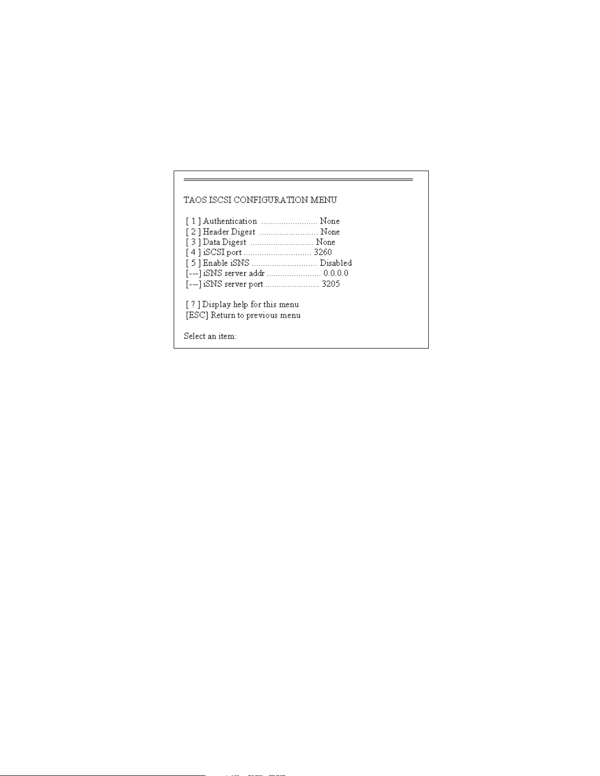
2. Configure iSCSI using the TAOS iSCSI Configuration Menu (Figure 4-5).
Figure 4-5 The TAOS iSCSI Configuration Menu.
The TAOS iSCSI Configuration Menu gives you the following options:
[1] Authentication: Choose an authentication method: CHAP, SRP or None.
[2] Header Digest: Choose a header digest: CRC-32 or None.
[3] Data Digest: Choose a data digest: CRC-32 or None.
[4] iSCSI Port: The default iSCSI port number is 3260. This is the IANA assigned
port for iSCSI and should not be modified under normal conditions.
[5] Enable iSNS: Choose to enable or disable iSNS. When iSNS is enabled it is
necessary to specify the IP address of the iSNS server.
[6] iSNS Server Address: Enter the IP address of the iSNS server. This must be a valid
server IP whenever iSNS is enabled.
[7] iSNS Server Port: The default port (3205) is assigned by IANA and should not be
modified under normal conditions.
[?] Help: Displays help for this menu.
[ESC] Return to previous menu: Returns you to the TAOS Configuration Menu.
3. Press Esc to return to the TAOS Configuration Menu.
There will be an asterisk (*) next to the menu option, indicating that an unsaved
change has been made.
35
Page 36

Chapter 4. Using the Serial Port Interface
4. Select 9 to save the changes.
5. Select y when prompted to reboot.
Note: You must reboot the NAStape in order for the new iSCSI
parameters to take effect.
Check Release Notes for availability of SRP.
36
Page 37
Chapter 4. Using the Serial Port Interface
NDMP Setup
Enabling NDMP
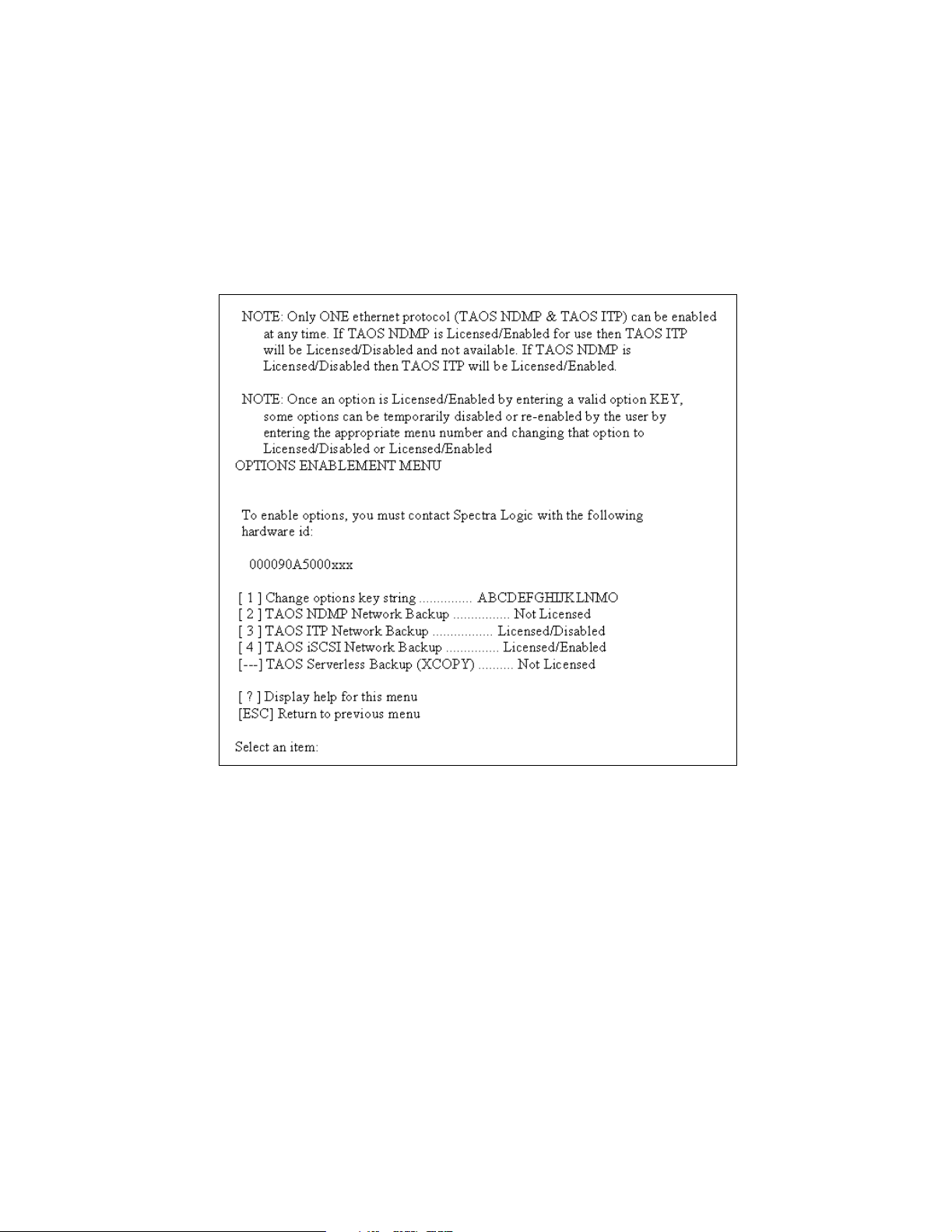
Through the Options Enablement Menu, verify that NDMP is licensed and enabled
(Figure 4-6).
Figure 4-6 The Options Enablement Menu.
•If NDMP Network Backup is not licensed, obtain and enter the activation key from
Spectra Logic.
•If NDMP is not enabled, select 2 to toggle enabled/disabled.
37
Page 38
Chapter 4. Using the Serial Port Interface
Configuring NDMP
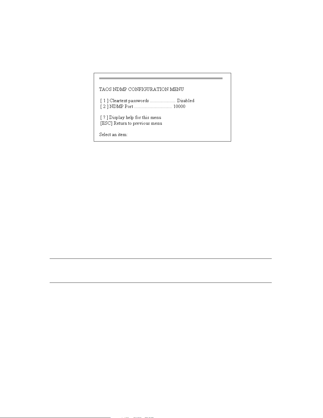
1. Select 5 from the TAOS Configuration Menu to access the TAOS NDMP
Configuration Menu (Figure 4-7).
Figure 4-7 The TAOS NDMP Configuration Menu.
The TAOS NDMP Configuration Menu gives you the following options:
[1] Cleartext passwords Select 1 to either enable or disable cleartext passwords.
[2] NDMP Port Select 2 to set the NDMP port.
2. Press Esc to return to the TAOS Configuration Menu.
There will be an asterisk (*) next to the menu option, indicating that an unsaved
change has been made.
3. Select 9 to save the changes.
4. Select y when prompted to reboot.
Note: You must reboot the NAStape in order for the new NDMP
parameters to take effect.
38
Page 39
Chapter 4. Using the Serial Port Interface
Enabling Options
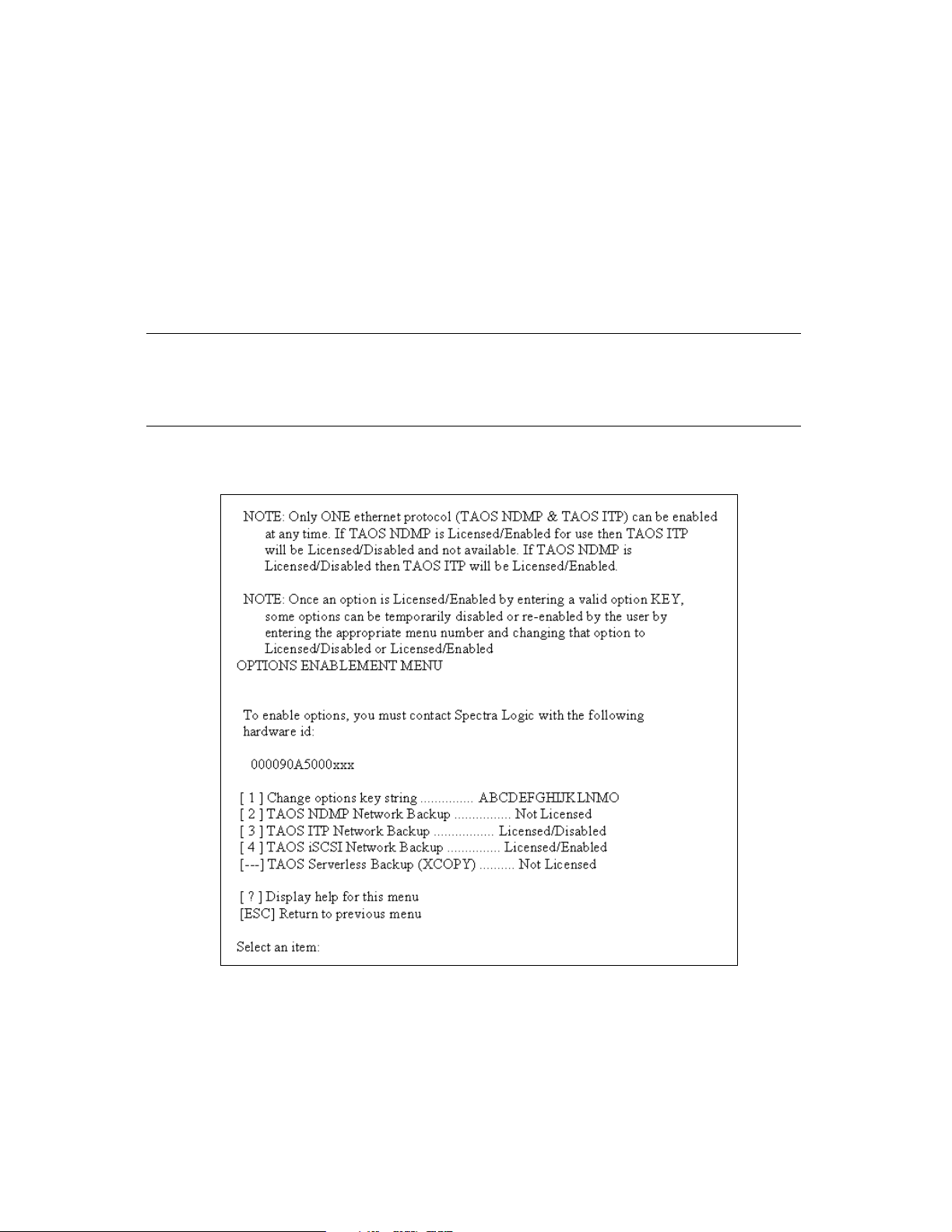
The Option Enablement Menu (Figure 4-8) allows you to enable and disable options on
the NAStape. Looking at the options available on the menu, you will see that the
options exist in the following states:
Not Licensed This option is not available until purchased and activated with a key code.
Licensed/Disabled The option has been purchased but is currently inactive.
Note: Ethernet storage devices may have only one protocol active at any
given time. Enabling one Ethernet protocol will automatically
disable all other Ethernet protocols that are currently licensed.
Licensed/Enabled The option is currently licensed and active.
[
Figure 4-8 The Options Enablement Menu.
1. To launch the Options Enablement Menu, select 8 from the TAOS Configuration
Menu.
2. Contact Spectra Logic with the identifier of the device, as shown in Figure 4-8,
to obtain an activation code that will enable options for this device.
39
Page 40

Chapter 4. Using the Serial Port Interface
The Option Enablement Menu gives you the following options:
[1] Change options key string: Enter the activation key code from Spectra Logic to
enable options for this NAStape.
Caution: Do not enter or save invalid activation keys. This could disable
existing options.
Backup Options [2-5]: Typing in the option number will toggle the option between
the enabled state and the disabled state.
[?]: Displays help for this menu.
[Esc]: Returns you to the TAOS Configuration Menu
3. Press Esc to return to the TAOS Configuration Menu.
There will be an asterisk (*) next to the menu option, indicating that an unsaved
change has been made.
4. Select 9 to save the changes.
5. Select y when prompted to reboot.
Note: You must reboot the NAStape in order for the new options to take
effect.
Jumbo Frames
The use of Jumbo Frames on the Gigabit Ethernet network can enhance performance.
Enlarging the packet size, or maximum transfer unit (MTU), from 1,500 bytes to 9,000
bytes reduces the overhead in the processing of the data over the Ethernet. Fewer
packets are processed, and the CPU load is decreased. Additionally, tape drives
perform better when they are kept fed (streaming) with data. To enable Jumbo Frames,
increase the MTU on the filers, Gigabit Ethernet switch, and the backup host’s Ethernet
adapter. The Ethernet interface on the NAStape will automatically negotiate for the
MTU size.
40
Page 41

Chapter 4. Using the Serial Port Interface
Host Bus Adapters
To enable Jumbo Frames, the MTU parameter should be increased on the Gigabit
Ethernet host bus adapter (HBA) or on the network interface card (NIC) on the unit
and on Network Appliance. You can do this through the ifconfig command on
Solaris and Network Appliance systems. On Windows NT and Windows 2000 systems,
the MTU size is configured in the driver. Check the Network Settings for the adapter
under the Control Panel. Each manufacturer implements this differently, so be sure to
check the HBA documentation for details on support of Jumbo Frames.
41
Page 42

Chapter 4. Using the Serial Port Interface
NDMP Backup Application Notes
Most NDMP backup applications work in a three-way configuration. A host computer
runs the backup application, one or more filers contain the data to be backed up, and
a tape server contains the NAStape and device resource. All three of these components
must be present and must be able to communicate with each other over the network.
Whenever possible, all three components should be on the same subnet.
To configure most backup applications, you must know about the devices attached to
the NDMP tape server. In the NDMP environment, the NAStape device is named as
Tape1_0.
The backup application will also want to know the host name of the NDMP tape
server. This hostname is the name that was assigned in the Ethernet setup section of
this manual. The backup application will also need to know the user name and
password that it should use for the tape server device. This is the same user name and
password assigned to the NAStape in NDMP Setup on page 37.
The recommended user name and password for this purpose is root.
Most backup applications will need the full pathname to the device. The pathname will
be <hostname>:Tape1_0, where the hostname is the name assigned in the Ethernet
setup section; for example: spectra0:Tape1_0.
Network Appliance Filer Setup
The filer will need some setup in order to interact with the NDMP agent. Since data
will flow to the NAStape on a backup, there are steps that are required to authorize
access to the data on the filer.
First, the filer must recognize the NAStape by its hostname. This is accomplished by
adding an entry to the /vol/vol0/etc/hosts file on the filer. The format is the
same as the hosts file on the backup host; for example: 10.0.0.254 spectra0.
Verify that the filer can successfully ping each NAStape to which it will be backing up;
for example: ping spectra0.
42
Page 43

5 Using the NAStape
This chapter covers the following information:
• Powering On and Off
• Checking Connection Status
• Upgrading Firmware
• Purchasing Media and Cleaning Cartridges
Powering On and Off
The NAStape unit power switch is located on the NAStape’s rear panel, just to the right
of the fan (Figure 5-1).
Power switch
Figure 5-1 The NAStape power switch (NAStape 100 shown).
Checking Connection Status
To review the status of NAStape unit connections, use the configuration tools described
in Configuration.
43
Page 44

Chapter 5. Using the NAStape
Upgrading Firmware
For specific information on upgrading NAStape firmware, contact Spectra Logic
Technical Support at (800) 227-4637 or (303) 449-0160.
Purchasing Media and Cleaning Cartridges
Certified media and cleaning cartridges can be purchased directly from Spectra Logic’s
Web site or by calling your sales representative.
Contacting Spectra Logic
Information
Web Site http://www.spectralogic.com
Supplies and Accessories Sales
United States Sales Phone: (800) 833-1132 or (303) 449-6400
Fax: (303) 939-8844
E-mail: sales@spectralogic.com
European Sales Phone: +44 (0) 870 112 2150
Fax: +44 (0) 870 112 2175
E-mail: eurosales@spectralogic.com
Ordering Media Web Site: http://www.SpectraLogic.com/media
E-mail: media@spectralogic.com
44
Page 45

6 NAStape 100 Tape Drives and Media
The NAStape 100 uses a Sony AIT tape drive, either AIT-2 or AIT-3. The Sony AIT tape
drive is a high-performance, low-maintenance tape drive. This chapter covers the
following information:
• AIT Tape Drives
• AIT Tape Drive LEDs
• Maintaining the AIT Tape Drive
• Caring for AIT Data Cartridges
• Handling of Tape Cartridges
AIT Tape Drives
The AIT tape drive has an internal, variable-speed fan that cools the baseplate and
other drive components without introducing airborne dust into the tape path. The fan,
visible from the outside of the NAStape, is also a critical part of the drive-cooling
mechanism.
The Sony AIT drive uses a built-in head cleaner designed to last for the life of the drive.
This built-in cleaner works well, but it should not be relied upon as the only drivecleaning mechanism, particularly in environments where more excessive drive head
contamination may occur. Spectra Logic recommends that drives be cleaned after every
100 hours of use in normal data center environments. If excessive read or write errors
occur while the drives are being cleaned with that frequency, Spectra Logic
recommends cutting the cleaning time to every 50 hours of drive use.
Caution: Drive cleaning should be performed using only approved Sony
SDX-TCL cleaning cartridges. For ordering information, see
Purchasing Media and Cleaning Cartridges on page 44.
For more information about cleaning your drives, see Tape Drive Head Cleaning on
page 48.
45
Page 46

Chapter 6. NAStape 100 Tape Drives and Media
AIT Tape Drive LEDs
The AIT tape drive has three light emitting diodes, or LEDs, on the front of the drive,
as shown in Figure 6-1
.
LEDs
Figure 6-1 The AIT drive sled, showing its faceplate and LEDs.
Busy Indicates drive read and write activity.
Tape Indicates tape load, unload activity and error rate information.
Status Indicates the status of the tape drive including whether the tape inside is write
protected, is a cleaning tape, or if the drive failed a self test.
46
Page 47

Chapter 6. NAStape 100 Tape Drives and Media
Getting Information from the LEDs
The following table summarizes the information carried by the blinking methods of the
different drive LEDs:
LED Type
Type of Blink
a
Off
b
On
Fast Blink
Slow Blink
c
d
Busy Tape Status
Not Busy Unloaded N/A
SCSI Active Loaded Write protected
Drive active Loading/Unloading Cleaning tape at EOM
N/A Error Rate Warning: data may
be written incorrectly
Single Pulse
Double Pulse
a. Off: no color in the LED
b. On: green* and not blinking
c. Fast blink: blinks green* for 1/4 second and off for 1/4 second
d. Slow blink: blinks green* for 3-1/2 seconds and off for 1/2 second
e. One pulse: blinks green* for 1/4 second and off for 1 second
f. Two pulse: blinks green* for 1/4 second twice in a row then off for 1 second
* A green light on an AIT-2 drive is equivalent to a blue light on an AIT-3 drive.
e
f
Waiting for reset Waiting for eject N/A
N/A N/A Self-test failure: power
Cleaning request
cycle the NAStape to reset
If the drive’s Tape LED indicates possible errors with the data on that tape, the errors
may be caused by old media or physical damage to the media. Resolve the problem by
copying the data to another tape and discarding the old tape.
47
Page 48

Chapter 6. NAStape 100 Tape Drives and Media
Maintaining the AIT Tape Drive
The AIT tape drive is an extremely reliable media storage subsystem; performing a few
simple maintenance procedures will keep the drives reading and writing reliably for
many years.
• For best performance with AIT tape drives, perform a read/write confidence test
with your backup software regularly. For information about performing this
operation, see the documentation for your backup software.
• As explained in AIT Tape Drives on page 45, the drive cleans itself when necessary.
If further cleaning is necessary, as indicated by the drive LED light and/or by the
read/write confidence test, use only Sony SDX-TCL cleaning cartridges. For
ordering information, see Purchasing Media and Cleaning Cartridges on page 44.
Tape Drive Head Cleaning
Head cleaning with a Sony SDX-TCL cleaning cartridge should be performed in the
following situations:
• Every 100 hours of drive use (or less) in the following situations:
• When the NAStape has been installed in areas having high amounts of airborne
particulates.
• When the drive fails to write or read data correctly.
• When the drive fails to eject a data cartridge.
Note: Damaged media can also cause read/write errors and failures.
Most installations require scheduled cleaning using SDX-TCL cleaning cartridges.
Scheduled cleaning is definitely required in installations having high amounts of
airborne particulates.
To clean your AIT tape drives, follow these steps:
1. Power on the NAStape.
2. Carefully insert the Sony SDX-TCL cleaning tape into the drive with the window
facing the top of the drive. The cleaning tape performs automatic cleaning and
ejects the cartridge when complete.
Caution: Do not use the cleaning cartridge for more than the number of
specified cleaning cycles indicated on the cartridge label. Mark
the cleaning cartridge each time you use it or use backup
software to track cleaning cartridge usage.
48
Page 49

Chapter 6. NAStape 100 Tape Drives and Media
Caring for AIT Data Cartridges
Although AIT cartridges are ruggedly built, they must be handled with care to preserve
the data that they contain. The following are guidelines for storing and using AIT
cartridges:
• Do not open the tape access door of the cartridge or touch the magnetic tape; one
fingerprint can prevent a drive from reading the tape. Handle only the plastic tape
cartridge.
• Keep the cartridge away from sources of electromagnetic fields such as telephones,
dictation equipment, mechanical or printing calculators, motors, stereo speakers,
and bulk erasers. Do not lay cartridges on a computer monitor or on the base unit
of a computer.
• Keep the cartridge away from direct sunlight and heat sources, such as radiators
and warm air ducts.
• Keep the cartridge free of moisture. Do not wet or submerge a cartridge in liquid.
• Do not expose the cartridge to temperature extremes. Allow the cartridge to reach
room temperature slowly.
Handling of Tape Cartridges
Proper handing of tape cartridges is essential to insuring data integrity.
• Tape cartridges must be kept in a clean, dust-free environment. Store tape
cartridges in a sealed container (the individual tape case or the 15-slot cartridge
packs with the dust cover installed) when they are not loaded in the NAStape. The
Spectra Logic Pack RackTM cartridge storage system is recommended when using
the 15-cartridge pack.
• Avoid abusive handling or dropping of tape cartridges. If a cartridge is
inadvertently dropped, inspect it for damage. The dust cover on the cartridge must
be properly seated or it could cause a jam condition in the tape drive.
• Cartridges should be used within the environmental specifications described in
Appendix A. Specifications on page 71.
Note: Extreme changes in temperature and humidity should be avoided
whenever possible.
Conditioning Cartridges
Before use, the cartridge should be conditioned by exposure to the operating
environment for a time at least equal to the period during which it has been out of the
operating environment (up to a maximum of 24 hours).
49
Page 50

Chapter 6. NAStape 100 Tape Drives and Media
50
Page 51

7 NAStape 200 Tape Drives and Media
The NAStape 200 uses a half-inch tape drive that could be any of the following:
• HP First Generation Linear Tape Open (LTO-1) Ultrium
• IBM Second Generation Linear Tape Open (LTO-2) Ultrium
• Quantum Super Digital Linear Tape (SDLT) 320
The following sections provide detailed information about the care and use of the tape
drive inside the NAStape 200, as well as the media used in that tape drive. See
Appendix A. Specifications on page 71 for tape drive specifications.
51
Page 52
Chapter 7. NAStape 200 Tape Drives and Media
HP Ultrium Generation 1 Tape Drives
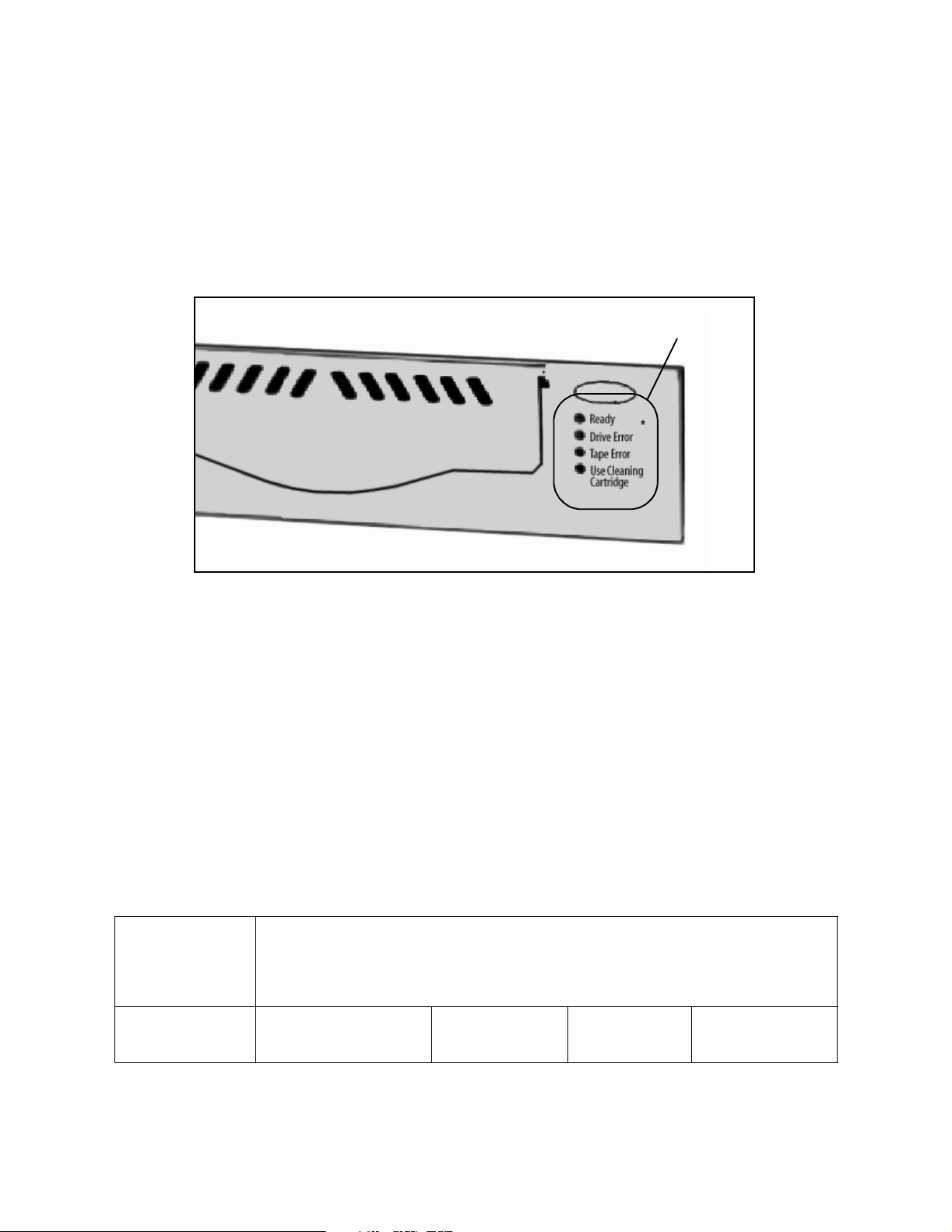
HP Ultrium Tape Drive LEDs
The HP Ultrium tape drive has four light emitting diodes (LEDs) on the front of the
drive, as shown in Figure 7-1.
LEDs
Figure 7-1 The HP LTO-1 drive face, showing its LEDs.
Ready This green LED indicates power and activity.
Drive Error This amber LED indicates an error in the drive.
Tape Error This amber LED indicates an error in the tape cartridge.
Use Cleaning Cartridge This amber LED indicates when a cleaning cartridge should be used.
Getting Information from the LEDs
The following table summarizes the information carried by the blinking methods of the
different drive LEDs:
LED Type
Use Cleaning
Type of Blink
Off Power is off, or there was a
Ready Drive Error Tape Error
failure during self-test.
No fault has been
detected.
No fault has been
detected.
Cartridge
Drive does not require
cleaning.
52
Page 53

Chapter 7. NAStape 200 Tape Drives and Media
LED Type
Use Cleaning
Type of Blink
On Ready for use. N/A N/A Cleaning cartridge in
Ready Drive Error Tape Error
Cartridge
use; the Ready LED
will also flash.
Flashing Active. Unrecoverable hard-
ware failure.
Flashing Pattern In OBDR mode. N/A N/A N/A
a. A power cycle or a successful tape load will turn off the LED; but if the hardware fault is still present, it will come on again if the same
operation is performed.
b. This LED could come on for a number of reasons. Do not use the cartridge; replace it. The LED will go out when a new tape load is started.
c. The LED will continue to flash if power is cycled; it will only go out after an approved cleaning cartridge has been used.
a
Tape cartridge is
b
faulty.
Drive needs cleaning.
c
Maintaining the HP Ultrium Tape Drive
HP Ultrium tape drives have been developed to require minimal cleaning. The amber LED for Use
Cleaning Cartridge will flash when the drive needs to be cleaned. Only insert a cleaning cartridge
into the drive when the LED indicates to do so.
Note: Drive cleaning should be performed using only approved HP
Ultrium cleaning cartridges; other cleaning cartridge formats will
not load or run.
To order approved cleaning cartridges from Spectra Logic, see
Purchasing Media and Cleaning Cartridges on page 44.
Manually Cleaning the HP Ultrium Tape Drive Head
To clean your HP Ultrium tape drives, follow these steps:
Note: Use only HP Ultrium cleaning cartridges.
1. Power on the NAStape.
2. Carefully insert the cleaning tape into the drive with the window facing the top
of the drive.
The cleaning tape performs automatic cleaning; this takes approximately five
minutes.
53
Page 54

Chapter 7. NAStape 200 Tape Drives and Media
Note: If the cartridge ejects immediately, it has either expired or it is not
an approved cleaning cartridge. In this case, discard the cartridge
and begin the cleaning procedure with a new cartridge.
During the cleaning cycle, the amber Use Cleaning Cartridge LED will remain on
and the green Ready LED will flash.
3. The drive ejects the cartridge when complete; remove the cleaning cartridge
from the drive.
Caution: Do not use the cleaning cartridge for more than the number of
specified cleaning cycles indicated on the cartridge label. Mark
the cleaning cartridge each time you use it or use backup
software to track cleaning cartridge usage.
Caring for HP Ultrium Media
Choosing Media
Use only LTO Ultrium cartridges. Compatible media is recognizable by the Ultrium
logo, which is the same as the logo on the front of the drive.
Caring for HP Ultrium Media
In optimal environments, LTO cartridges are should last for 1,000,000 passes over any
part of the tape (this equals approximately 2,000 complete backup and restore
operations). These numbers should, however, be limited in harsher environments.
Caution: If you are using bar code labels, make sure that only one label is
attached to the label area.
Never use non-standard labels, and never attach anything to the
cartridge other than in the label area.
Using HP Ultrium Media
Only use LTO Ultrium media within its operating range requirements (see Appendix A.
Specifications). If you expose the media to conditions that exceed these limits, stabilize
the media before use. To do this, keep the media out of use in the operating
environment for at least 24 hours.
54
Page 55

Chapter 7. NAStape 200 Tape Drives and Media
Storing HP Ultrium Media
Only store LTO Ultrium media within its operating range requirements (see Appendix
A. Specifications). Make sure that the environment is clean, and always store cartridges
in their plastic cases.
Maximizing HP Ultrium Media Life
To maximize the life of your HP Ultrium media, follow these guidelines.
• Do not touch the surface of the tape inside the cartridge.
• Do not attempt to clean the tape path or the tape guides inside the cartridge.
• Do not expose the tapes to excessively dry or excessively humid conditions.
• Do not leave the cartridges in direct sunlight.
• Do not leave the cartridges in places where magnetic fields are present (such as
under telephones, next to monitors, or near transformers).
• Do not drop the cartridges or handle them roughly.
Avoiding Condensation
Condensation can cause problems for tape drives and media. To minimize the chance
of condensation, stay within specifications and observe the following guidelines.
• Make sure that the operating environment is stable (away from windows, doors,
and heating or cooling sources).
• Avoid leaving cartridges in severe temperature conditions (such as in a car).
• Avoid transferring data when the temperature is changing by more than 18oF (16oC)
per hour.
• If you bring a cold cartridge into a warm room, allow time for the cartridge to
adjust to room temperature before use (up to 24 hours).
55
Page 56
Chapter 7. NAStape 200 Tape Drives and Media
IBM Ultrium Generation 2 Tape Drives
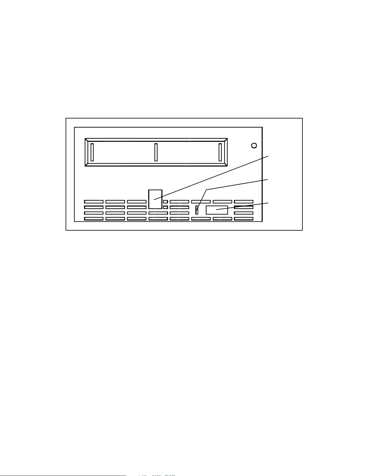
IBM Ultrium Tape Drive LEDs
The IBM Ultrium tape drive has four light emitting diodes (LEDs) on the front of the
drive, as shown in Figure 7-1.
Single
character
display
Status
light
Unload
button
Figure 7-2 The IBM LTO-2 drive face, showing its LEDs.
Single-character display This LED presents a single-character code for:
• Error conditions and informational messages
• Diagnostic or maintenance functions (while in maintenance mode only)
Status light This LED provides information about the state of the drive. The light can be
green or amber, and (when lit) solid or flashing.
Unload button This button is used for ejecting tapes from the unit as well as for initiating
various maintenance functions.
Getting Information from the LEDs
When the LED is off, it means that the unit has no power or is powered off.
56
Page 57

Chapter 7. NAStape 200 Tape Drives and Media
The following table summarizes the information given by the blinking methods of the
status light LED:
LED Color
Indication
Green Amber
Solid The drive is powered on.
If a solid C appears in the single-character display, the drive needs cleaning.
Flashing The drive is reading from the tape, writing to the
tape, rewinding the tape, locating data on the
tape, loading the tape, or unloading the tape.
The status light also flashes green if the drive
contains a cartridge during the power-on cycle.
In this case, the drive completes writing the current data and slowly rewinds the tape (the process may take up to 13 minutes). The light stops
blinking when the drive completes the recovery
and is ready for a read or write operation.
Getting Information from the Single-Character Display
The drive is powering on or is in maintenance mode.
One of the following applies:
- If the light flashes once per second, an error occurred
and the tape drive or media may require service. (Note
the code on the single-character display, then go to
Error Conditions and Informational Messages on page
57 to determine the action that is required.)
- If the light flashes twice per second, the tape drive is
updating firmware.
- If the light flashes four times per second, the tape
drive detected an error and is performing a firmware
recovery. It resets automatically.
Error Conditions and Informational Messages If multiple errors occur, the code with the highest
priority (represented by the lowest number) displays first. When the error is corrected,
the code with the next highest priority displays, and so on until no errors remain.
Code Cause and Solution
No error occurred and no action is required. This code displays:
- When power is cycled.
0
- When diagnostics have finished running and no error occurred.
Cooling problem. The tape drive detected that the recommended operating temperature was exceeded.
Perform one or more of the following actions:
- Ensure that the cooling fan is rotating and is quiet.
- Remove any blockage that prevents air from flowing freely through the tape drive.
- Ensure that the operating temperature and airflow is within the specified range.
- If the operating temperature is within the specified range and the problem persists, replace the drive.
1
The error code clears when you power-off the tape drive or place it in maintenance mode.
57
Page 58

Chapter 7. NAStape 200 Tape Drives and Media
Code Cause and Solution
Power problem. The tape drive detected that the externally supplied power is approaching the specified
voltage limits (the tape drive is still operating) or is outside the specified voltage limits (the tape drive is
not operating). Perform the following:
- Ensure that the power connector is properly seated.
- Ensure that the proper dc voltages are being applied within the tolerances allowed.
- If the proper voltages are being applied but the problem persists, replace the drive.
2
The error code clears when you power-off the tape drive or place it in maintenance mode.
Note: The single-character display is blank during normal operation.
Diagnostics and Maintenance To initiate a function, you must be in maintenance mode. For
more information, see Functions of the Unload Button on page 59.
Function Code
Run Tape Drive Diagnostics
Runs tests and determines whether the drive can properly load and unload cartridges and read and write data. 1
Update Tape Drive Firmware from FMR Tape
Load updated firmware from a field microcode replacement (FMR) tape. 2
Create FMR Tape
Copies the drive’s FMR data to a scratch (blank) data cartridge. 3
Force a Drive Dump
Performs a dump of data (also known as saving a microcode trace). 4
Copy the Drive Dump to Tape (at Beginning of Tape)
Copies data from a drive dump (captured by using Function Code 4) to the beginning of a scratch (blank) tape. 5
Run SCSI Wrap Test
Performs a check of the SCSI circuitry from and to the SCSI connector. 6
Run RS-422 Wrap Test
Not available. 7
Unmake FMR Tape
Erases the FMR data on a scratch (blank) tape and rewrites the cartridge memory on the tape.
This turns the cartridge into a valid scratch data cartridge. 8
a
Display Error Code Log
Display the last 10 error codes, one at a time (the most recent is presented first and the oldest is presented last). 9
Clear Error Code Log
Erases the contents of the error code log. A
58
Page 59

Chapter 7. NAStape 200 Tape Drives and Media
Function Code
a
Insert Cartridge into Tape Drive
This function cannot be selected by itself; it is a part of other functions that require a tape be loaded. C
Test Cartridge & Media
Performs tests to ensure that a suspect cartridge and its magnetic tape are acceptable. E
Fast Read/Write Test
Performs tests to ensure that the drive can read from and write to tape. F
Test Head
Performs tests to ensure that the tape drive’s head and tape-carriage mechanics are working correctly. H
Exit Maintenance Mode
The drive becomes available for reading and writing data. 0
a. The single-character display is blank during normal operation.
Functions of the Unload Button
The Unload push button enables you to perform several functions. The following table
lists the functions and explains how to initiate them.
Function How To Initiate
Rewind the tape into a cartridge
and eject the cartridge from the
tape drive.
Place the tape drive in maintenance mode.
Press the unload button once.
Note: During a rewind and eject operation, the drive will not accept SCSI commands from the server.
Ensure that the tape drive is unloaded. Then, within two seconds push the unload
button three times.
The drive is in maintenance mode when the status light becomes solid amber and
a 0 appears in the single-character display.
Note: While in maintenance mode, the drive will not accept SCSI commands from
the server.
Scroll through the
maintenance functions.
While in maintenance mode, push the unload button once per second to increment the characters on the single-character display by one. When you reach the
character of the diagnostic or maintenance function that you want (see Diagnos-
tics and Maintenance on page 58), press and hold the unload button for three seconds.
Exit maintenance mode. Press the unload button once per second until a 0 appears in the single-character
display. Then press and hold the unload button for three seconds.
The drive has exited maintenance mode when the status light becomes solid
green and the single-character display becomes blank.
59
Page 60

Chapter 7. NAStape 200 Tape Drives and Media
Note: If you press the Unload button during operation, the drive ends
the command that is being processed, then unloads and ejects the
tape. Depending on its location on the reel, the tape may take as
long as 20 minutes to completely rewind and eject.
Maintaining the IBM Ultrium Tape Drive
Note: When cleaning the IBM Ultrium tape drive head, use only IBM LTO
Ultrium cleaning cartridges. You may use another LTO cleaning
cartridge, but it may not meet the standards of reliability
established by IBM.
To order approved cleaning cartridges from Spectra Logic, see
Purchasing Media and Cleaning Cartridges on page 44.
Cleaning the Drive Head
Clean the drive head whenever C displays on the single-character display and the status
light is solid green. IBM does not recommend that you clean the drive head on a
periodic basis, but only when C displays.
To clean the head:
1. Insert the cleaning cartridge into the tape load compartment.
The tape drive performs the cleaning automatically. The cleaning cycle takes less
than two minutes.
2. When the cleaning is finished, the drive ejects the cartridge. Remove the
cartridge.
Note: If you insert a cleaning cartridge when the drive does not need to
be cleaned or if you insert a cleaning cartridge that has expired,
the drive will automatically eject the cartridge.
The IBM LTO Ultrium cleaning cartridge is valid for 50 uses. Be sure to mark the
cartridge after each use to keep track of how many times it is used.
60
Page 61

Chapter 7. NAStape 200 Tape Drives and Media
Caring for IBM Ultrium Media
Caring for IBM Ultrium Media
Caution: Do not insert a damaged cartridge into the drive. A damaged
cartridge can interfere with the reliability of the drive and may
void the warranties of the drive and the cartridge.
Before inserting a tape cartridge, inspect the cartridge case, cartridge door, and writeprotect switch for breaks. Incorrect handling or an incorrect environment can damage
the LTO Ultrium tape cartridge or its magnetic tape. To avoid damage to your tape
cartridges and to ensure the continued high reliability of your drive, use the following
guidelines:
• Do not drop the cartridge. If the cartridge drops, slide the cartridge door back and
ensure that the leader pin is properly seated in the pin-retaining spring clips.
Inspect the rear of the cartridge (the part that you load first into the tape load
compartment) and ensure that there are no gaps in the seam of the cartridge case.
• Open only the cartridge door. Do not open any other part of the cartridge case. The
upper and lower parts of the case are held together with screws; separating them
destroys the usefulness of the cartridge.
• Do not handle tape that is outside the cartridge. Handling the tape can damage the
tape’s surface or edges, which may interfere with read or write reliability. Pulling on
tape that is outside the cartridge can damage the tape and the brake mechanism in
the cartridge.
• Before you use a cartridge, let it acclimate for at least 24 hours to the normal
operating environment.
• Ensure that all surfaces of a cartridge are dry before inserting it.
• Do not stack more than six cartridges.
• Do not expose the tape cartridge to moisture or direct sunlight.
• Do not degauss a tape cartridge that you intend to reuse. Degaussing makes the
tape unusable.
• Do not expose recorded or blank tape cartridges to stray magnetic fields (such as
terminals, motors, video equipment, X-ray equipment, or high-current cables or
power supplies). Such exposure can cause the loss of recorded data or make the
blank cartridge unusable.
• Maintain the environmental conditions specified in Appendix A. Specifications.
61
Page 62

Chapter 7. NAStape 200 Tape Drives and Media
Quantum SDLT 320 Tape Drives
SDLT 320 Tape Drive LEDs
The tape drive has three light emitting diodes, or LEDs, on the front of the drive, as
shown in Figure 7-3.
Drive
Density
Status
Cleaning
Required
Eject button
Infrared
Port
Figure 7-3 The SDLT drive sled, showing its faceplate and LEDs.
Density LED This amber LED indicates whether the tape in the drive is of the
SDLT-220 format or SDLT-320 format.
Status LED This green LED indicates the tape drive status.
Cleaning LED This yellow LED indicates cleaning requirements and functions.
Eject This button ejects the tape cartridge from the drive. When the button is pressed,
the drive completes any writing of data to the tape, and then ejects the cartridge.
Infrared Port This infrared port, also known as the Global Storage Link (GSLink),
provides a wireless remote testing base for customers and integrators to access system
diagnostic information.
62
Page 63

Chapter 7. NAStape 200 Tape Drives and Media
Getting Information from the LEDs
The following table summarizes the information carried by the blinking methods of the
different drive LEDs:
LED Type
Indication
Off The tape in the drive is
On The tape in the drive is
Blinking N/A The tape drive is in use. This includes:
If the drive’s Status LED indicates possible errors with the data on that tape, the errors
may be caused by old media or physical damage to the media. Resolve the problem by
copying the data to another tape and discarding the old tape.
Density Status Cleaning
SDLT-320 format.
SDLT-220 format.
The unit has not been turned on or is not plugged
into a power source.
The drive is idle. There may or may not be a cartridge
in the tape drive.
• Calibrating, reading, writing, or rewinding the tape.
• Loading or unloading.
Cleaning is not
required.
Cleaning is
required.
N/A
Maintaining the SDLT Tape Drive
Cleaning Status
The Cleaning Required (yellow) LED on the front panel indicates to the operator that
cleaning is needed.
Note: Use the SDLT cleaning tape if cleaning is indicated through your
backup software or when the yellow alert light is on. Do not clean
the drive unless the drive indicates that cleaning is necessary.
Once illuminated, the yellow LED stays lit until one of the following occurs:
• The drive is cleaned successfully.
• The drive is reset due to a firmware failure or firmware update.
• Power is cycled off and on.
Cleaning the SDLT Tape Drive Head
The SDLT cleaning tape is housed in a plastic case, and is light gray in color. Use only
approved SDLT cleaning cartridges. To order these cartridges from Spectra Logic, see
Purchasing Media and Cleaning Cartridges on page 44.
63
Page 64

Chapter 7. NAStape 200 Tape Drives and Media
A yellow LED located on the front bezel of the tape drive indicates when cleaning is
needed (the location of this LED is shown in Figure 7-3 on page 62).
Clean the NAStape as follows:
1. Power on the NAStape.
2. Carefully insert the cleaning tape into the drive with the window facing the top
of the drive.
3. The cleaning tape performs automatic cleaning and ejects the cartridge when
complete.
Note: Do not use the cleaning cartridge more than 20 times. Mark the
cleaning cartridge each time you use it or use backup software to
track cleaning cartridge usage.
Load Time for Cleaning Cartridge
Load (cycle) times for SDLT cleaning cartridges are as follows; these times are accurate
to ±20 seconds:
• Shortest load time (first pass of cleaning cartridge): 2 minutes 55 seconds
• Longest load time (20th pass of cleaning cartridge): 10 minutes 20 seconds
• Expired load time (expired cleaning tape): 4 minutes 30 seconds
On the last pass, the cleaning process stops, the tape is rewound, but the cartridge is
not ejected. If the tape is loaded again after the 20th pass, it winds all the way to the
end of the cartridge and back again without performing the cleaning sequence; the
tape does not eject.
Caution: Never use a DLT cleaning tape in an SDLT drive; DLT cleaning
tapes are incompatible with the SDLT heads.
64
Page 65

Chapter 7. NAStape 200 Tape Drives and Media
Caring for SDLT Media
Super DLTtape I cartridges are engineered to be reliable, robust, and durable. They are
manufactured to withstand 1,000,000 passes, and have a shelf life of 30 years. For best
results, follow these guidelines for media care:
• Protect cartridges from shock, vibration, moisture, and magnetic fields.
• Keep media in protective cases at all times.
• Store cartridges vertically when not in use.
• Use the sliding labels provided. Do not use adhesive labels and do not write on the
cartridge.
• Never touch the tape or tape leader. Dust and oils from your skin contaminate the
tape and affect performance.
• If you drop a cartridge, perform a visual media inspection before inserting it into
the drive.
Note: The safety of your data relies on proper care and handling of
media cartridges.
Refer to the environmental specifications provided in the plastic
cartridge case, or in Appendix A. Specifications on page 71, for
detailed media information.
Handling SDLT Tape Cartridges
Improper media handling is the primary reason for tape drive problems. Mishandled
and damaged cartridges lead to damaged drives. If the cartridge does not pass the
following criteria, do not use it.
To inspect a cartridge:
1. Inspect the exterior of the cartridge for physical damage, cracks, or broken
parts.
2. Gently shake the cartridge. Listen for rattling of loose pieces.
3. Check to make sure that both reel locks on the cartridge are visible. One reel
lock is located on the end of the cartridge that is inserted into the drive. The
other is on the bottom of the cartridge.
4. Confirm that the spring-loaded hub on the bottom of the cartridge is centered.
Press the hub to ensure that the spring is functioning properly.
5. Verify that the orange write-protect switch is enabled and undamaged.
65
Page 66

Chapter 7. NAStape 200 Tape Drives and Media
Conditioning Cartridges
Before use, the cartridge should be conditioned by exposure to the operating
environment for a time at least equal to the period during which it has been out of the
operating environment (up to a maximum of 24 hours).
66
Page 67

8 Warranty and Repair
This chapter reviews the NAStape warranty and Spectra Logic’s repair policies.
Limited Warranty
Spectra Logic warrants the NAStape unit to be in good working order for a period of
three full years from the date of shipment from Spectra Logic or an authorized Spectra
Logic dealer. Should this product fail to be in good working order at any time during
this three-year period, Spectra Logic will, at its option, repair or replace this product at
no additional charge except as follows:
Suspect parts sent to Spectra Logic will be repaired or replaced. Exchanged parts will
be either reconditioned or new at the option of Spectra Logic. This limited warranty
does not include:
• Service to repair damage resulting from accident
• Disaster, misuse, and abuse
• Non-Spectra Logic modification of the product including, but not limited to,
product expansion through plug-in additions except as provided by Spectra Logic
• Removal of serial number tags
• Physical damage caused by inadequate packaging
• Tape head cleaning performed on drives provided by Spectra Logic with a noncertified cleaning cartridge
• Drives purchased from vendors other than Spectra Logic
If any of the above conditions exist, Spectra Logic reserves the right to repair the unit
at the current fixed price of repair.
Warranty service can be acquired during the three-year period by shipping the product
to Spectra Logic with an invoice and Return Materials Authorization (RMA) number.
Note: No return can be accepted without an RMA number from Spectra
Logic Technical Support. Returns must be shipped prepaid in their
original packing containers; damage incurred in transit is not
covered by Spectra Logic's warranty.
67
Page 68

Chapter 8. Warranty and Repair
Spectra Logic makes no other warranties, expressed or implied, and specifically
disclaims any warranty of merchantability or fitness for a particular purpose or use. If
this product is not in good working condition as warranted above, your sole remedy
shall be replacement or repair as provided above. In no event will Spectra Logic be
liable to you for any damages, including any lost profits, lost savings, or other
incidental or consequential damages arising out of the use of or inability to use such
product, even if Spectra Logic has been advised of the possibility of such damages, or
for any claim by any other party.
Warranty Shipping
The NAStape unit must be returned in the original carton and packed with the original
packing material. Failure to do so will void the warranty. See the label on the inside lid
of the shipping container for instructions on packing the NAStape.
The purchaser is responsible for paying the shipping and insurance charges for
warranty goods to Spectra Logic. Spectra Logic will pay for shipping the repaired item
back to the purchaser.
International warranty repairs must be accompanied by a commercial invoice, a
packing slip, and a carrier waybill. The following must be written on the invoice:
GOODS OF U.S. ORIGIN, RETURN FOR WARRANTY REPAIR, VALUE FOR CUSTOMS USE ONLY.
Import duties assessed on incoming shipments will be prorated to the customer’s
account if proper documentation does not accompany the shipment.
Warranty Turnaround Time
A standard repair turnaround time is two weeks from receipt of the product. Spectra
Logic shall reserve the right to replace the unit if it cannot be repaired within the two
week time frame. A 48-hour turnaround is available for an additional charge.
Warranty Provisions for Units Located in Europe
Spectra Logic has implemented special arrangements for honoring warranties on
libraries located in Europe. Please contact Spectra Logic Technical Support for details.
Out-of-Warranty Repairs
Contact Technical Support for the current fixed repair price for NAStape. The repair is
warranted for ninety days from the date the unit is shipped to a customer.
Out-of-Warranty Shipping
All non-warranty units will be shipped back to the purchaser as determined by the
purchaser. Shipping charges to and from Spectra Logic are the responsibility of the
68
Page 69

Chapter 8. Warranty and Repair
purchaser. International customers with non-warranty units are responsible for
customs and duties charges coming into the United States as well as charges on
returned products into their own countries.
Out-of-Warranty Turnaround Time
The non-warranty turnaround time is two weeks from receipt of the unit. An expedited
turnaround of 48 hours is available for an additional fee. Spectra Logic reserves the
right to either repair or replace the unit.
QuickSwap Service
The QuickSwap program covers the NAStape for the original return-to-factory period
(three years from the date of shipment) at no cost to the customer. The program
includes:
• Access to a Spectra Logic Technical Support representative any business day (not
including evenings, weekends, or holidays) from 8:00 a.m. to 5:00 p.m. Mountain
Time (MT).
• Upon verification that the product has malfunctioned, the replacement part or unit
will be shipped to the customer.
• The replacement arrives within five to seven business days. The replacement can be
expedited from the Spectra Logic manufacturing line for an additional charge.
Contact your sales or service representative for more information.
• The customer returns the defective part or unit within 10 days of receipt of the
replacement.
This program covers the product for the original return-to-factory period (three years
from the date of shipment) at no cost to the customer.
Advanced Service Options
There are three advanced technical support services available on a contractual basis.
• Advanced Replacement Service
• Next Business Day On-Site Service
• Four-Hour On-Site Service
Please contact Technical Support for the contract pricing for these options.
69
Page 70

Chapter 8. Warranty and Repair
Contacting Spectra Logic
Information
Web Site http://www.spectralogic.com
Technical Assistance
Technical Support Phone United States: (800) 227-4637 or (303) 449-60160
Europe: +44 (0) 870 112 2185
Technical Support E-Mail support@spectralogic.com
Knowledge Base http://www.spectralogic.com/support/kbase/index.cfm
RMA Number for Equipment Service and Returns
Technical Support Phone United States: (800) 227-4637 or (303) 449-60160
Europe: +44 (0) 870 112 2185
Technical Support E-Mail support@spectralogic.com
Shipping Information
To ship the NAStape for any reason, reverse the procedure in Unpacking the NAStape,
making sure to use the original packaging materials.
The following table lists the size and weight of the NAStape for shipping purposes.
NAStape 100 NAStape 200
Height 3.5 in. (8.9 cm) 5.9 in. (15.0 cm)
Width 7.4 in. (18.8 cm) 9.8 in. (24.9 cm)
Depth 11.5 in. (29.2 cm) 13.5 in. (34.3 cm)
Weight 8.5 lbs. (3.9 kg) 15 lbs. (6.8 kg)
Caution: Do not ship the NAStape with a cartridge in the tape drive.
70
Page 71

Appendix A. Specifications
This appendix contains the following information:
• NAStape Power Requirements
• NAStape Safety Specifications
• NAStape Environmental Specifications
• Sony AIT Specifications
• HP LTO Ultrium Generation 1 Specifications
• IBM LTO Ultrium Generation 2 Specifications
• Quantum SDLT 320 Specifications
NAStape Power Requirements
Power requirements for NAStape are summarized in the table below.
Source Requirements
Input Voltage 100/240 Volts AC
1.0/.5 A
Input Power 90 Watts minimum
120 Watts maximum
Input Frequency 50/60 Hz
Power Cable
The power cable included with NAStape is a standard, three conductor, 18 AWG power
cord safe for 120-volt use in the United States and Canada. The cable has a molded
NEMA 5-15P male connector to plug in the wall and a molded IEC 60320-type female
connector to plug in the NAStape unit.
Note: To use the NAStape unit outside of the United States or Canada,
the power cord must meet the specifications for that country.
71
Page 72

Appendix A. Specifications
240 Volt-AC Power Cord for Use in North America
The criteria for a U.S. and Canadian 240 volt AC power cord for the NAStape are as
follows:
• Power cord must have a molded NEMA 6-15P attachment plug on one end.
• Power cord must have a molded IEC 60320-type female connector to connect to the
NAStape unit.
• Cordage must be SJT type, three-conductor, 18 AWG minimum.
• Power cord must comply with local electrical code.
200-240 Volt-AC Power Cord for International Use
The criteria for an international 200-240 volt AC power cord are as follows:
• Power cord must have an attachment plug of the proper type, rating, and safety
approval for the intended country.
• Power cord must have a molded IEC 60320-type female connector to connect to the
NAStape.
• Cord must be a flexible, HAR (harmonized) type H05VV-F, three conductor, cord
with minimum conductor size of 0.03 square inches (1.0 square millimeter).
NAStape Safety Specifications
• Indoor use only
• Ordinary Protection: This product is not protected against the harmful ingress of
moisture.
• Pollution Degree 2 for ambient pollution.
• Installation (Overvoltage) Category II for transient overvoltages.
• Mains Supply: Voltage fluctuations are not to exceed ± 10% of the rated nominal
voltage range.
72
Page 73

Appendix A. Specifications
NAStape Environmental Specifications
Place the NAStape unit and media in a reasonably controlled environment that does
not exceed the environment limits listed in the table below.
Condition Minimum Maximum
Ambient Operating Temperature 2
Storage Temperature -40
Relative Humidity (non-condensing) 20% 80%
Max. wet bulb temperature N/A 26
Altitude 0 m (sea level) 3,000 m (9,842 ft)
To allow for proper cooling and to maintain the proper temperature of the NAStape,
leave at least six (6) inches of open space behind the unit.
° C 30° C
° C 65° C
° C
73
Page 74

Appendix A. Specifications
Sony AIT Specifications
Drive Specifications
The following table summarizes the specifications for Sony AIT drives.
Parameter AIT-2 Specification
a
AIT-3 Specification
a
MTBF 300,000 hours @ 100% duty cycle 400,000 hours @ 100% duty cycle
Average file access time Less than 27 seconds Less than 27 seconds
-17
Uncorrectable error rate Less than 1 x 10
Sustained transfer rate
Burst transfer rate
a. All specifications are subject to change without notice.
b. Compression thoughput and capacity depends on the type of data.
c. The actual burst data transfer rate is limited by the performance of the SCSI host bus adapter, the SCSI bus interface controller, and
the buffer control hardware of the drive.
b
c
6 MB/sec native (15 MB/sec compressed) 12 MB/sec native (31 MB/sec compressed)
40 MB/sec Synchronous maximum 160 MB/sec Synchronous maximum
bits Less than 1 x 10
-17
bits
Media Specifications
The table below lists the capacities of the different types of AIT tape cartridges.
Tape Type Length Capacity
AIT-2 (SDX2-36C) 170 meters 36 GB native (94 GB compressed with ALDC)
a
AIT-2 (SDX2-50C) 230 meters 50 GB native (130 GB compressed with ALDC)
AIT-3 (SDX3-100C) 230 meters 100 GB native (260 GB compressed with ALDC)
a. All specifications are subject to change without notice.
Environmental Specifications
The table below lists the environmental specifications of AIT tape cartridges.
a
Factor
Operating temperature
b
Operating humidity 20% to 80% non-condensing
Maximum wet bulb temperature +77°F (+25°C)
a. All specifications are subject to change without notice.
b. The upper limit applies to the drive, not to the NAStape. Be sure there is adequate air flow around NAStape at all times.
Operating Environment
+41°F to +104°F (+5°C to +40°C)
74
Page 75

Appendix A. Specifications
HP LTO Ultrium Generation 1 Specifications
Drive Specifications
Parameter Specification
a
MTBF 250,000 hours @ 100% duty cycle
Average file access time 71 seconds
Uncorrectable error rate 1 x 10
b
Sustained transfer rate
-17
bits
7.5 MB/sec native
15 MB/sec compressed
Burst transfer rate
a. All specifications are subject to change without notice.
b. Compression thoughput and capacity depends on the type of data.
c. The actual burst data transfer rate is limited by the performance of the SCSI host bus adapter, the SCSI bus
interface controller, and the buffer control hardware of the drive.
c
80 MB/sec synchronous maximum
Media Specifications
The table below lists the capacity of HP LTO-1 tape cartridges.
Tape Type Capacity
a
LTO Ultrium Generation 1 100 GB native (200 GB compressed with LTO-DC)
a. All specifications are subject to change without notice.
Environmental Specifications
The table below lists the environmental specifications of HP LTO-1 tape cartridges.
a
Factor
Operating Environment
Temperature +50°F to +95°F (+10°C to +35°C)
Relative Humidity 20% - 80% non-condensing
a. All specifications are subject to change without notice.
b. The upper limit applies to the drive, not to the NAStape. Be sure there is adequate air flow around
NAStape at all times.
b
75
Page 76

Appendix A. Specifications
IBM LTO Ultrium Generation 2 Specifications
Drive Specifications
Parameter Specification
Average file access time 65 seconds
Uncorrectable error rate 1 x 10
Sustained transfer rate b
Burst transfer rate
a. All specifications are subject to change without notice.
b. Compression thoughput and capacity depends on the type of data.
c. The actual burst data transfer rate is limited by the performance of the SCSI host bus adapter, the SCSI bus
interface controller, and the buffer control hardware of the drive.
c
-17
35 MB/sec native
70 MB/sec compressed
80 MB/sec Synchronous maximum
a
bits
Media Specifications
The table below lists the capacity of IBM LTO-2 tape cartridges.
Tape Type Capacity
LTO Ultrium Generation 2 200 GB native (400 GB compressed with DLZ)
a
a. All specifications are subject to change without notice.
Environmental Specifications
The table below lists the environmental specifications of IBM LTO-2 tape cartridges.
a
Factor
Temperature +50°F to +113°F
Relative
Humidity
Wet Bulb
Temperature
a. All specifications are subject to change without notice.
b. The upper limit applies to the drive, not to the NAStape. Be sure there is adequate air flow around NAStape at all times.
Operating
(+10°C to +45°C)
10% - 80% 20% - 80% 20% - 50% 5% - 80%
+79°F (+26°C) +79°F (+26°C) +79°F (+26°C) +79°F (+26°C)
b
Operational Storage Archival Storage Shipping
+61°F to +90°F
(+16°C to +32°C)
76
+61°F to +77°F
(+16°C to +25°C)
-9°F to +120°F
(-23°C to +49°C)
Page 77

Appendix A. Specifications
Quantum SDLT 320 Specifications
Drive Specifications
Parameter Specification
a
MTBF 250,000 hours @ 100% duty cycle
Average file access time 70 seconds
Uncorrectable error rate 1 x 10
b
Sustained transfer rate
-17
bits
16 MB/sec native
32 MB/sec compressed
Burst transfer rate
a. All specifications are subject to change without notice.
b. Compression thoughput and capacity depends on the type of data.
c. The actual burst data transfer rate is limited by the performance of the SCSI host bus adapter, the SCSI bus
interface controller, and the buffer control hardware of the drive.
c
80 MB/sec Synchronous maximum
Media Specifications
The table below lists the capacity of SDLT tape cartridges.
Tape Type Capacity
a
Super DLTtape 1 160 GB native (320 GB compressed with DLZ)
a. All specifications are subject to change without notice.
Environmental Specifications
The table below lists the environmental specifications of SDLT tape cartridges.
a
Factor
Operating Environment
Temperature +50°F to +95°F (+10°C to +35°C) +61°F to +90°F (+16°C to +32°C)
Relative Humidity 20% - 80% non-condensing 20% - 80% non-condensing
a. All specifications are subject to change without notice.
b. The upper limit applies to the drive, not to the NAStape. Be sure there is adequate air flow around NAStape at all
times.
b
77
Storage Environment
Page 78

Appendix A. Specifications
78
Page 79

Appendix B. Regulatory and Safety Notices
This appendix lists the following regulatory and safety notices:
• Safety Agency Standards
• FCC Notice
• Japan VCCI-A
• EU Declaration of Conformity
Safety Agency Standards
The NAStape unit complies with the following regulatory and safety standards, and
bears the CE and VCCI marks:
• EN 60950-1: 2001
• CSA/UL 60950
FCC Notice
This equipment has been tested and found to comply with the limits for a Class A
digital device, pursuant to Part 15 of the FCC rules. These limits are designed to
provide reasonable protection against harmful interference when the equipment is
operated in a commercial environment. This equipment generates, uses, and can
radiate radio frequency energy and, if not installed and used in accordance with the
instruction manual, may cause harmful interference to radio communications.
Operation of this equipment in a residential area is likely to cause harmful
interference, in which case the user will be required to correct the interference at his
own expense.
Shielded cables are required for this device to comply with FCC rules.
79
Page 80
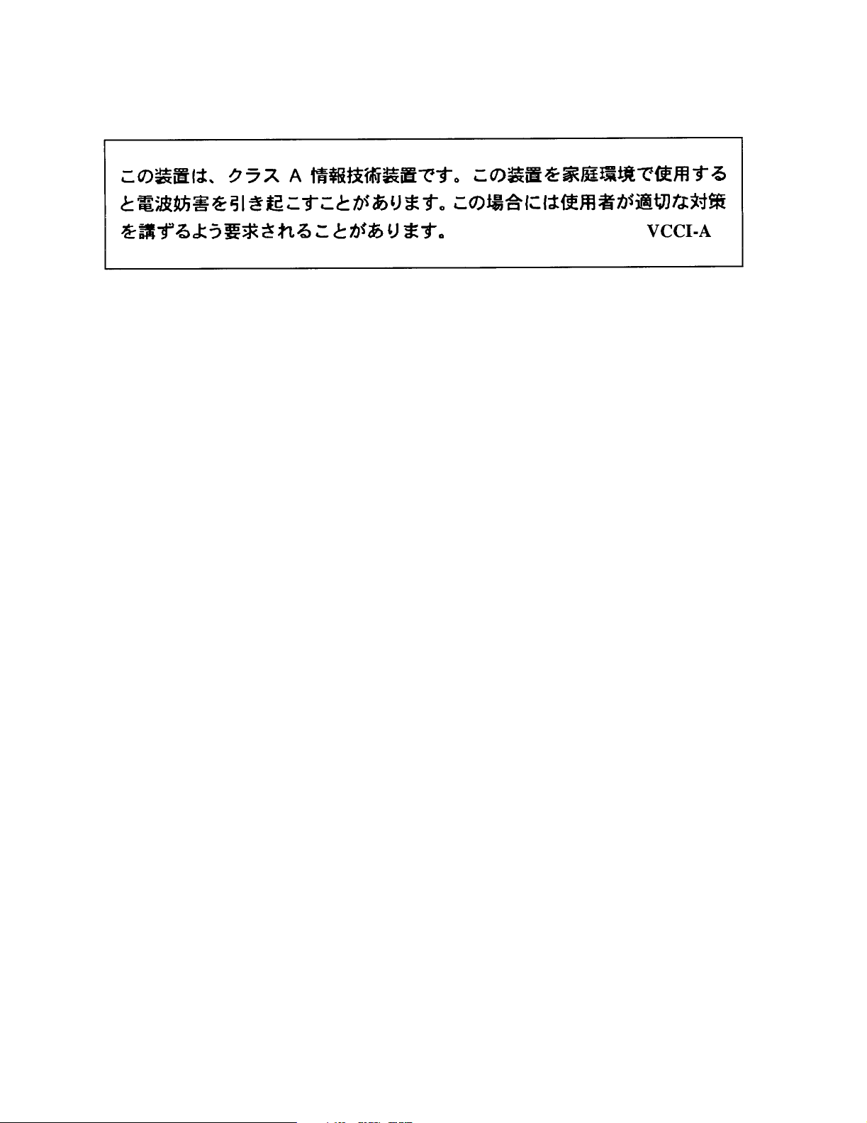
Japan VCCI-A
Appendix B. Regulatory and Safety Notices
80
Page 81

Appendix B. Regulatory and Safety Notices
EU Declaration of Conformity
We, Spectra Logic Corporation
1700 North 55th Street
Boulder, Colorado 80301 USA
declare under sole responsibility that Spectra Logic’s NAStape, to which this declaration
relates,
the EU Directives listed below using the relevant section of the following EU standards
and other normative documents:
EU Low Voltage Directive 73/23/EEC Essential health and safety requirements relating to electrical equipment designed
EN 55022 (CISPER 22) Class A Limits and methods of measurements of radio interference characteristics of
EN 60950-1 (IEC 60950-1) Safety requirements of information technology equipment including electrical
meets the essential health and safety requirements and is in conformity with
for use within certain voltage limits.
information technology equipment.
machines.
EN 61000-4-2 (1995) Electrostatic discharge requirements for industrial process measurement and control
equipment.
EN 61000-4-3 (1996),
ENV 50204 (1995)
EN 61000-4-4 (1995) Electrically fast transients for industrial process measurement and control
EN 61000-4-5 (1995) Electrical surge immunity for industrial process measurement and control
EN 61000-4-6 (1996) Conducted radio frequency immunity for industrial process measurement and control
EN 61000-4-8 (1993) Power frequency magnetic field immunity for industrial process measurement and
EN 61000-4-11 (1994) Immunity to voltage dips, interruptions and variations for industrial process
EN 61000-3-2 (1998) Power Line Harmonics, Class A.
EN 61000-3-3 (1998) Power Line Flicker.
Radiated electromagnetic field requirements for industrial process measurement and
control equipment.
equipment.
equipment.
equipment.
control equipment.
measurement and control equipment.
EU EMC Directive 89/336/EEC Essential health and safety requirements relating to electromagnetic compatibility.
81
Page 82

Appendix B. Regulatory and Safety Notices
The NAStape complies with all safety-relevant provisions referring to:
• Protection against electrical hazards
• Protection against hazards such as:
• Mechanical hazards
• Fire hazards
•Noise
•Vibration
The CE marking has been affixed on the device according to Article 10 of the EU
Directive 89/336/EEC and 73/23/EEC.
82
Page 83

Index
A
about
AIT tape drives 45
iSCSI 10
LTO-1 tape drives 52
LTO-2 tape drives 56
NAStape 9
NDMP 10
SDLT tape drives 62
this user guide 12
AC power 71
accessories
included 14
purchasing additional 44
AIT cleaning cartridges
ordering 44
using 48
AIT media
maintenance 49
purchasing 44
specifications 74
AIT tape drives
about 45
cleaning 48
LEDs 46, 47
specifications 74
using 45
B
C
cautions
as conventions 12
media 4
NAStape 4
cleaning
AIT tape drives 48
LTO-1 tape drives 53
LTO-2 tape drives 60
SDLT tape drives 63
configuring
Ethernet 22
password 32
connecting to
HTTP interface 17
serial port 29
Web interface 17
contact information
Spectra Logic 2, 70
controller information
from HTTP interface 27
conventions used in this guide 12
D
drive information
from HTTP interface 27
drives (see drive type)
backup application notes
NDMP 42
83
Page 84

Index
E
e-mail Spectra Logic
ordering media 44
technical support 70
enable NDMP 37
environmental specifications
AIT tape drives 74
LTO-1 tape drives 75
LTO-2 tape drives 76
NAStape 73
SDLT tape drives 77
Ethernet
configuration 22
jumbo frames 40
serial port configuration 33
F
I
IBM LTO-2 (see LTO-2)
installation 13
environment 13
iSCSI
about 10
protocols 24
serial port configuration 35
J
jumbo frames 40
K
Knowledge Base 70
fax Spectra Logic 2
filer setup
Network Appliance 42
H
hardware environment 13
high voltage
warning 4
HP LTO-1 (see LTO-1)
HTTP interface
connecting 17
device information 27
security 28
using 17
L
LEDs
AIT tape drive 46
LTO-1 tape drive 52
LTO-2 tape drive 56, 57
SDLT tape drive 62
legal
license 3
limited warranty 67
notices 2
repair policy 67
license, legal 3
limited warranty 67
LTO-1 cleaning cartridges
ordering 44
using 53
84
Page 85

LTO-1 media
maintenance 54
purchasing 44
specifications 75
LTO-1 tape drives
about 52
cleaning 53
LEDs 52
specifications 75
using 52
LTO-2 cleaning cartridges
ordering 44
using 60
LTO-2 media
maintenance 61
purchasing 44
specifications 76
LTO-2 tape drives
about 56
cleaning 60
LEDs 56, 57
specifications 76
using 57, 58, 59
M
maintenance
AIT media 49
cleaning tape drives 48
LTO-1 media 54
LTO-2 media 61
SDLT media 65
media
AIT specifications 74
caution 4
LTO-1 specifications 75
LTO-2 specifications 76
purchasing 44
SDLT specifications 77
Index
N
NAStape
about 9
accessories
included 14
purchasing additional 44
cautions 4
environment 13
environmental specifications 73
information from HTTP interface 27
installation 13
repair policy 67
restart 27
returns 70
service 70
shipping 70
unpacking 14
using 43
warnings 4
warranty 67
NDMP 37
about 10
backup application notes 42
enable options 37
protocols 26
Network Appliance
filer setup 42
notes
as conventions 12
NDMP backup application 42
notices, legal 2
O
out-of-warranty repairs 68
85
Page 86

Index
P
password
HTTP interface 28
serial port configuration 32
phone Spectra Logic 2
sales 44
technical support 70
policies
limited warranty 67
repair 67
power
cable 71
international requirements 72
NAStape requirements 71
US requirements 72
warning 4
protocols
about iSCSI 10
about NDMP 10
iSCSI 24
NDMP 26
Q
Quantum SDLT (see SDLT)
R
repair policy 67
out-of-warranty 68
requirements
NAStape power 71
restart NAStape 27
RMA numbers
contacting technical support 70
S
SDLT cleaning cartridges
ordering 44
using 63
SDLT media
maintenance 65
purchasing 44
specifications 77
SDLT tape drives
about 62
cleaning 63
LEDs 62, 63
specifications 77
security 28
serial port
connecting 29
Ethernet configuration 33
iSCSI configuration 35
password configuration 32
using 29
sharing tape devices 10
shipping
NAStape 70
under warranty 68
specifications
AIT media 74
AIT tape drives 74
LTO-1 media 75
LTO-1 tape drives 75
LTO-2 media 76
LTO-2 tape drives 76
NAStape environment 73
NAStape power 71
SDLT media 77
SDLT tape drives 77
86
Page 87

Spectra Logic
contacting 2
Knowledge Base 70
sales 44
technical support 70
e-mail 70
phone 70
Web site 44, 70
T
tape drives
(also see drive type)
about NAStape drives 9
technical support
contacting 70
Knowledge Base 70
RMA numbers 70
warranty policies 67
troubleshooting
Knowledge Base 70
U
unpacking the NAStape 14
user guide
intent 12
using
59
AIT tape drives 45
HTTP interface 17
LTO-1 tape drive 52
LTO-2 tape drives 56
NAStape 43
serial port 29
Web interface 17
Index
V
voltage
warning 4
W
warnings
AC power 4
as conventions 12
high voltage 4
NAStape 4
warranty 67
shipping 68
Web interface
configuration 21
connecting 17
device information 27
logout 28
maintenance 27
restart 27
security 28
status 19
using 17
Web site
Spectra Logic 2, 44, 70
Knowledge Base 70
87
 Loading...