

Page 1
Copyright © 2002 Spectra Logic Corporation. All rights reserved.
P.N. 92844007 Revision C
Page 2

Notices
Notices
Except as expressly stated herein, Spectra Logic Corporation makes available the Spectra 10000 Library and
associated documentation on an “as is” basis, without warranty of any kind, either expressed or implied,
including but not limited to the implied warranties of merchantability or fitness for a particular purpose. In
no event shall Spectra Logic be liable for any loss of profits, loss of business, loss of use or data, interruption
of business, or for indirect, special, incidental or consequential damages of any kind, even if Spectra Logic
has been advised of the possibility of such damages arising from any defect or error.
Information furnished in this manual is believed to be accurate and reliable. However, no responsibility
is assumed by Spectra Logic for its use. Due to continuing research and development, Spectra Logic may
revise this publication from time to time without notice, and reserves the right to change any product
specification at any time without notice.
Some products or services mentioned in this manual are provided by companies other than Spectra
Logic. Inquiries about one or more of these products or services should be sent directly to the company
in question. Where this manual refers to the brand or product names, their registered trademarks and
trademarks may be registered in this country, other countries, or both.
License Agreement
Purchase of a Spectra Logic tape library includes a license to use one copy of the control software. This
software is loaded into non-volatile RAM in the tape library and may be upgraded or reloaded from a
tape. This software may not be copied for use on another machine without the express written consent
of Spectra Logic.
This software license includes unlimited use on the Spectra Logic library hardware for which it was
purchased. The license applies to, but is not limited to, the number of slots in the carousel, the number
of drives in the library, and bar code capabilities.
A license to extend the capabilities or configuration of the software or hardware in this library may be
purchased from Spectra Logic or through an authorized Spectra Logic reseller. Purchase of an upgrade
through Spectra Logic or one of its authorized resellers implicitly includes an extension of the software
license to include the functionality for the component purchased.
Spectra Logic Contact Information
United States Office European Office
Mailing Address
Phone
Fax
Spectra Logic Corporation
1700 N 55th Street
Boulder CO 80301
USA
(800) 833-1132 or (303) 449-6400
(303) 939-8844
Mailing Address
Phone
Fax
Spectra Logic Europe Limited
Hampden House
Monument Business Park
Warpsgrove Lane
Chalgrove Oxon
UK-OX44 7RW
+44 (0) 870 112 2150
+44 (0) 870 112 2175
Web Site
http://www.spectralogic.com
2
Page 3

Warnings and Cautions
Tapes
Caution: Use only the data cartridges approved for use in the particular
drives installed in your Spectra 10000 library. Improper data
cartridges will result in damage to the drives, library and
cartridges.
Bar Code Scanner
Warning: Use of controls or adjustments or performance of procedures
other than those specified herein may result in exposure to
hazardous visible laser light.
Notices
AC Power
Warning: Risk of electrical shock. Do not remove the library cover. To
remove AC power from the library, unplug the power cord from
the power inlet. There are no user-serviceable parts within the
library.
Lithium Battery
Warning: The UCM board in the library contains a lithium battery. The
battery is not serviceable by the user. Return the UCM board to
Spectra Logic for proper service. Improper disposal could result
in an explosion.
3
Page 4

Rack Mounting
Cabling
Caution: Flat SCSI cables need a minimum rack depth of 27 inches, and
the rack must be EMI/RFI shielded. Round SCSI cables need a
minimum rack depth of 29 inches.
Caution: The library unit should be properly grounded to the rack
equipment. This ground connection must be maintained when
the supply connection is other than a direct connection to the
branch circuit.
Operating Environment
Caution: Installing library units in a rack system must not reduce the air
flow within the rack. The maximum recommended ambient
temperature for the library is 89.6°F (32°C).
Notices
Power
Safety
Caution: Make sure the power requirements of the library plus the
cumulative power draw of the other equipment in the rack do
not overload the supply circuit and/or wiring of the rack.
Warning: The library weighs approximately 61 pounds. Use caution when
lifting the library to install it in a rack. Ask for help when lifting
the library.
Warning: Always stack the rack from the bottom up to ensure a stable and
safe rack.
4
Page 5

Contents
Notices . . . . . . . . . . . . . . . . . . . . . . . . . . . . . . . . . . . . . . . . . . . . . . . . . . . . . . . . . 2
License Agreement . . . . . . . . . . . . . . . . . . . . . . . . . . . . . . . . . . . . . . . . . . . . . . . . . 2
Spectra Logic Contact Information . . . . . . . . . . . . . . . . . . . . . . . . . . . . . . . . . . . . . 2
Warnings and Cautions . . . . . . . . . . . . . . . . . . . . . . . . . . . . . . . . . . . . . . . . . . . . . 3
Chapter 1. Introduction 9
About This Guide . . . . . . . . . . . . . . . . . . . . . . . . . . . . . . . . . . . . . . . . . . . . . . . . . . 9
About the Spectra 10000 Library . . . . . . . . . . . . . . . . . . . . . . . . . . . . . . . . . . . . . . 10
Library Components . . . . . . . . . . . . . . . . . . . . . . . . . . . . . . . . . . . . . . . . . . . . . . . 11
Storage Management Options . . . . . . . . . . . . . . . . . . . . . . . . . . . . . . . . . . . . . . . . 18
Professional Services . . . . . . . . . . . . . . . . . . . . . . . . . . . . . . . . . . . . . . . . . . . . . . 20
Chapter 2. Preparing the Host System 21
Before Configuring the Library . . . . . . . . . . . . . . . . . . . . . . . . . . . . . . . . . . . . . . . 21
Selecting a SCSI Bus for the Library
(SCSI Libraries Only) . . . . . . . . . . . . . . . . . . . . . . . . . . . . . . . . . . . . . . . . . . . . . . 22
Determining SCSI ID Usage . . . . . . . . . . . . . . . . . . . . . . . . . . . . . . . . . . . . . . . . . 22
Sony AIT Device Driver Support . . . . . . . . . . . . . . . . . . . . . . . . . . . . . . . . . . . . . . 23
If You Need Assistance . . . . . . . . . . . . . . . . . . . . . . . . . . . . . . . . . . . . . . . . . . . . 23
5
Page 6

Contents
Chapter 3. Preparing the Library 25
Unpacking the Library . . . . . . . . . . . . . . . . . . . . . . . . . . . . . . . . . . . . . . . . . . . . . 25
Selecting an Appropriate Environment for the Library . . . . . . . . . . . . . . . . . . . . . . 26
Preparing to Connect the Library . . . . . . . . . . . . . . . . . . . . . . . . . . . . . . . . . . . . . 28
Selecting the Mode of Library Operation . . . . . . . . . . . . . . . . . . . . . . . . . . . . . . . . 29
Split-Bus Configuration . . . . . . . . . . . . . . . . . . . . . . . . . . . . . . . . . . . . . . . . . . . . 31
Setting SCSI IDs . . . . . . . . . . . . . . . . . . . . . . . . . . . . . . . . . . . . . . . . . . . . . . . . . . 36
Setting the Library Configuration Switch . . . . . . . . . . . . . . . . . . . . . . . . . . . . . . . . 38
Connecting the SCSI Cables and Terminators . . . . . . . . . . . . . . . . . . . . . . . . . . . . 39
Connecting the Serial Cable . . . . . . . . . . . . . . . . . . . . . . . . . . . . . . . . . . . . . . . . . 40
Connecting the Library to Fibre Channel . . . . . . . . . . . . . . . . . . . . . . . . . . . . . . . . 41
Connecting the AC Power . . . . . . . . . . . . . . . . . . . . . . . . . . . . . . . . . . . . . . . . . . 43
Chapter 4. Configuring the Library 45
Configuring Library Software . . . . . . . . . . . . . . . . . . . . . . . . . . . . . . . . . . . . . . . . 45
Setting Library Parameters . . . . . . . . . . . . . . . . . . . . . . . . . . . . . . . . . . . . . . . . . . 47
Fibre Channel Information Screen . . . . . . . . . . . . . . . . . . . . . . . . . . . . . . . . . . . . 51
Configuring Library Tape Drive Settings . . . . . . . . . . . . . . . . . . . . . . . . . . . . . . . . 54
Checking for Correct Operation . . . . . . . . . . . . . . . . . . . . . . . . . . . . . . . . . . . . . . 55
Chapter 5. Operating the Library 57
Inserting Tapes . . . . . . . . . . . . . . . . . . . . . . . . . . . . . . . . . . . . . . . . . . . . . . . . . . 58
Moving Tapes . . . . . . . . . . . . . . . . . . . . . . . . . . . . . . . . . . . . . . . . . . . . . . . . . . . 59
Removing Tapes . . . . . . . . . . . . . . . . . . . . . . . . . . . . . . . . . . . . . . . . . . . . . . . . . 60
Viewing and Enabling Bar Codes . . . . . . . . . . . . . . . . . . . . . . . . . . . . . . . . . . . . . 64
Creating a Backup Firmware Tape . . . . . . . . . . . . . . . . . . . . . . . . . . . . . . . . . . . . 67
Upgrading Library Firmware . . . . . . . . . . . . . . . . . . . . . . . . . . . . . . . . . . . . . . . . 68
Upgrading Drive Firmware . . . . . . . . . . . . . . . . . . . . . . . . . . . . . . . . . . . . . . . . . . 71
Using Passwords . . . . . . . . . . . . . . . . . . . . . . . . . . . . . . . . . . . . . . . . . . . . . . . . . 73
Copying Data From Non-AIT Tapes to AIT Tapes . . . . . . . . . . . . . . . . . . . . . . . . . 76
6
Page 7

Contents
Chapter 6. Maintaining the Library 79
Accessing Library Information . . . . . . . . . . . . . . . . . . . . . . . . . . . . . . . . . . . . . . . 80
Accessing Drive Information . . . . . . . . . . . . . . . . . . . . . . . . . . . . . . . . . . . . . . . . 81
Replacing the Air Filter . . . . . . . . . . . . . . . . . . . . . . . . . . . . . . . . . . . . . . . . . . . . 84
Changing Hosts . . . . . . . . . . . . . . . . . . . . . . . . . . . . . . . . . . . . . . . . . . . . . . . . . . 85
Cleaning Drives . . . . . . . . . . . . . . . . . . . . . . . . . . . . . . . . . . . . . . . . . . . . . . . . . . 86
Handling Tapes . . . . . . . . . . . . . . . . . . . . . . . . . . . . . . . . . . . . . . . . . . . . . . . . . . 88
Packing the Library for Shipment . . . . . . . . . . . . . . . . . . . . . . . . . . . . . . . . . . . . . 89
Additional Media and Accessories . . . . . . . . . . . . . . . . . . . . . . . . . . . . . . . . . . . . . 91
Ordering Media and Accessories . . . . . . . . . . . . . . . . . . . . . . . . . . . . . . . . . . . . . . 92
Chapter 7. Troubleshooting 93
Library Operation Problems . . . . . . . . . . . . . . . . . . . . . . . . . . . . . . . . . . . . . . . . . 94
Tape Drive Problems . . . . . . . . . . . . . . . . . . . . . . . . . . . . . . . . . . . . . . . . . . . . . .101
Bar Code Problems . . . . . . . . . . . . . . . . . . . . . . . . . . . . . . . . . . . . . . . . . . . . . . .103
Chapter 8. Technical Support and Service 105
Important Information . . . . . . . . . . . . . . . . . . . . . . . . . . . . . . . . . . . . . . . . . . . . .105
Spectra Logic Repair Policy . . . . . . . . . . . . . . . . . . . . . . . . . . . . . . . . . . . . . . . . .106
Advanced Technical Support Options . . . . . . . . . . . . . . . . . . . . . . . . . . . . . . . . . .108
Contacting Technical Support . . . . . . . . . . . . . . . . . . . . . . . . . . . . . . . . . . . . . . . .109
Professional Services . . . . . . . . . . . . . . . . . . . . . . . . . . . . . . . . . . . . . . . . . . . . . .110
7
Page 8

Contents
Appendix A. Library Specifications 111
Library Specifications . . . . . . . . . . . . . . . . . . . . . . . . . . . . . . . . . . . . . . . . . . . . . .111
Sony AIT Tape Drive Specifications . . . . . . . . . . . . . . . . . . . . . . . . . . . . . . . . . . .113
Sony AIT Media Specifications . . . . . . . . . . . . . . . . . . . . . . . . . . . . . . . . . . . . . . .116
Bar Code Specifications . . . . . . . . . . . . . . . . . . . . . . . . . . . . . . . . . . . . . . . . . . . .117
The SCSI Bus . . . . . . . . . . . . . . . . . . . . . . . . . . . . . . . . . . . . . . . . . . . . . . . . . . . .118
SCSI Cables and Terminators . . . . . . . . . . . . . . . . . . . . . . . . . . . . . . . . . . . . . . . .119
Appendix B. Regulatory and Safety Standards 125
Safety Agency Standards . . . . . . . . . . . . . . . . . . . . . . . . . . . . . . . . . . . . . . . . . . .125
FCC Notice . . . . . . . . . . . . . . . . . . . . . . . . . . . . . . . . . . . . . . . . . . . . . . . . . . . . .125
Japan . . . . . . . . . . . . . . . . . . . . . . . . . . . . . . . . . . . . . . . . . . . . . . . . . . . . . . . . .126
BMPT Vfg 243/1991 . . . . . . . . . . . . . . . . . . . . . . . . . . . . . . . . . . . . . . . . . . . . . .126
EU Declaration of Conformity . . . . . . . . . . . . . . . . . . . . . . . . . . . . . . . . . . . . . . . .127
Index 129
8
Page 9

1 Introduction
About This Guide
This guide describes the installation and operation of the Spectra 10000 library,
including troubleshooting information.
This guide addresses network administrators who maintain and operate their backup
systems. This guide assumes a familiarity with SCSI and/or Fibre Channel, as well as a
technical knowledge of tasks such as configuring operating systems, installing drivers,
and connecting cables.
Related Publications
These publications are also available from Spectra Logic:
•The Spectra 10000 Library Release Notes (P.N. 92844034) provides the most up-to-
date information about the library, drives, and media.
•The Spectra 10000 Library Developer Guide provides SCSI reference information
useful to application developers. It can be found on the Spectra Logic Web site at
http://www.spectralogic.com/support/index.cfm/fuseaction/displayProductDocs/.
Conventions Used in This Manual
This manual uses the following conventions to highlight extra information and to
emphasize important safety tips:
Note: Read the information marked Note for additional points or
suggestions about the topic or procedure being discussed.
Caution: Read the information marked Caution to learn ways to avoid
damaging the library, tape drives, or other equipment.
Warning: Read the information marked Warning to learn ways to avoid
personal injury.
9
Page 10

Chapter 1. Introduction
About the Spectra 10000 Library
The Spectra 10000 library configured for SCSI operation includes up to four Sony AIT
tape drives and one fixed tape carousel, which can store up to 43 data cartridges. The
robotics, controllable through SCSI-2 commands or through a Serial to SCSI Command
Language (SSCL) interface, are fast and reliable and certified for more than one million
actuations.
SCSI Configuration
When configured to use both wide/ultra LVD SCSI busses, with four AIT-3 drives using
AIT-3 data cartridges, the Spectra 10000 library can store up to 10.4 TB of compressed
data, with a transfer rate (compressed) of up to 124.8 Megabyte per second (MB/sec).
Note: HVD SCSI does not support Ultra-3 transfer rates.
The SCSI library’s reliable network backup lends itself to use in many different storage
management environments. See Storage Management Options on page 18 for some
examples of the different configurations in which the Spectra 10000 library can be
used.
Fibre Channel Configuration
The Spectra 10000 library configured for Fibre Channel offers exceptional data storage
capacity with the speed and flexibility offered by Fibre Channel connectivity. The highspeed Sony AIT drives in the library provide a high standard of performance and
reliability. The library’s integrated Fibre Channel interface board is equipped with a
gigabit interface converter (GBIC) module that allows users choose between copper
and optical cabling. This cabling spans a greater distance than SCSI—up to 10 km with
optical cabling and up to 30 meters with copper cabling—while achieving data transfer
speeds of up to 100 MB/sec.
The Fibre Channel library’s high-speed network backup lends itself to use in many
different storage management environments. See Storage Management Options on
page 18 for some examples of the different configurations in which the Spectra 10000
library can be used.
10
Page 11
Library Components
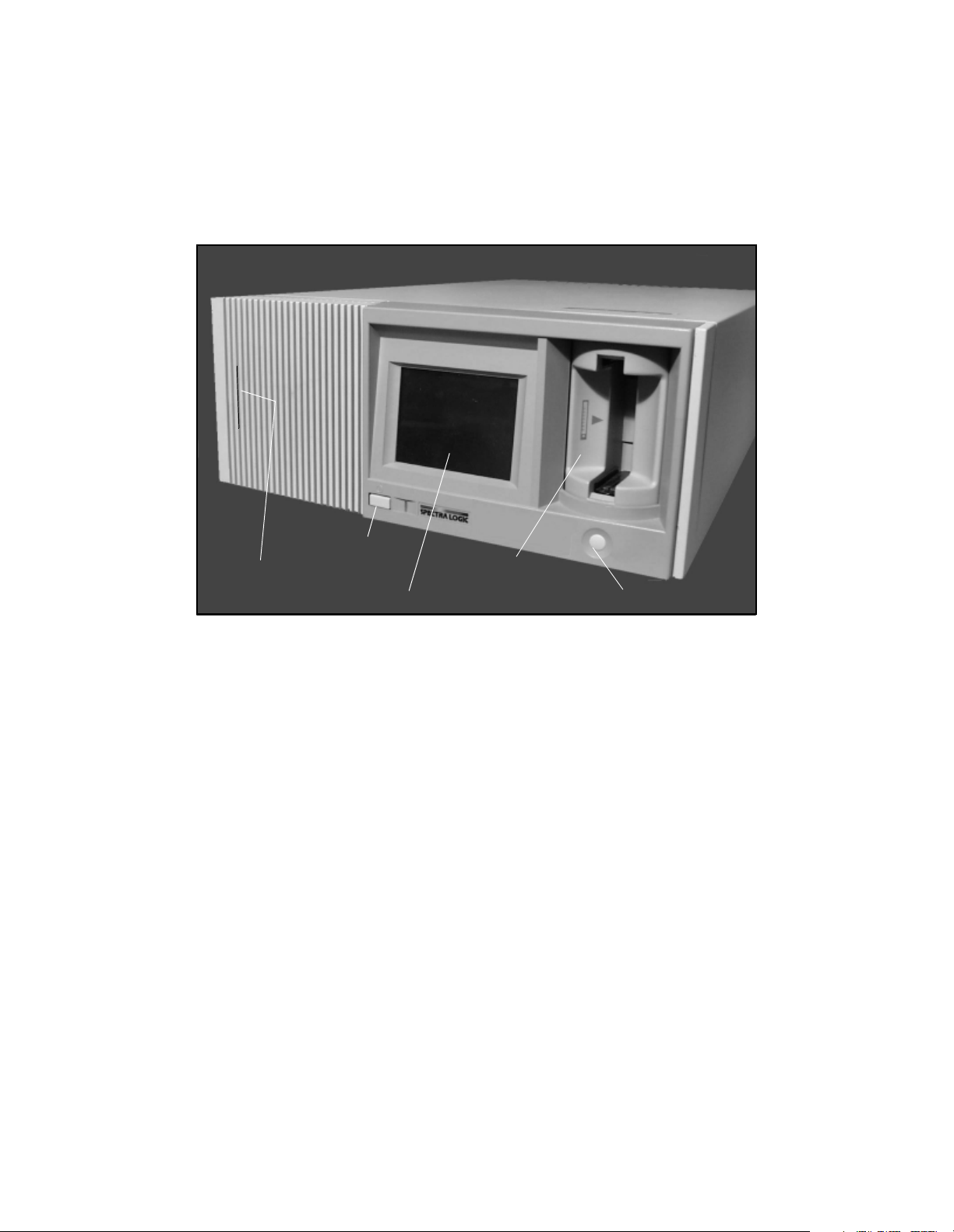
Front Panel Components
Chapter 1. Introduction
Power button
Front panel release
Touchs creen displ ay
Figure 1-1 The library’s front panel components.
Library door
Door button
Front Panel Release This releases the hinged front door panel when a plastic card is slid
through it, allowing you to access the library air filter for inspection or replacement.
Library Door The door allows you to load and unload tape cartridges.
Door Button The door button opens or closes the door, allowing you to insert or
remove cartridges.
Touchscreen Display The touchscreen display enables you to view library information
and access screens from which you can configure library settings. Read the following
section on the library’s menu screens for more information on how these screens can
be navigated.
11
Page 12
Chapter 1. Introduction
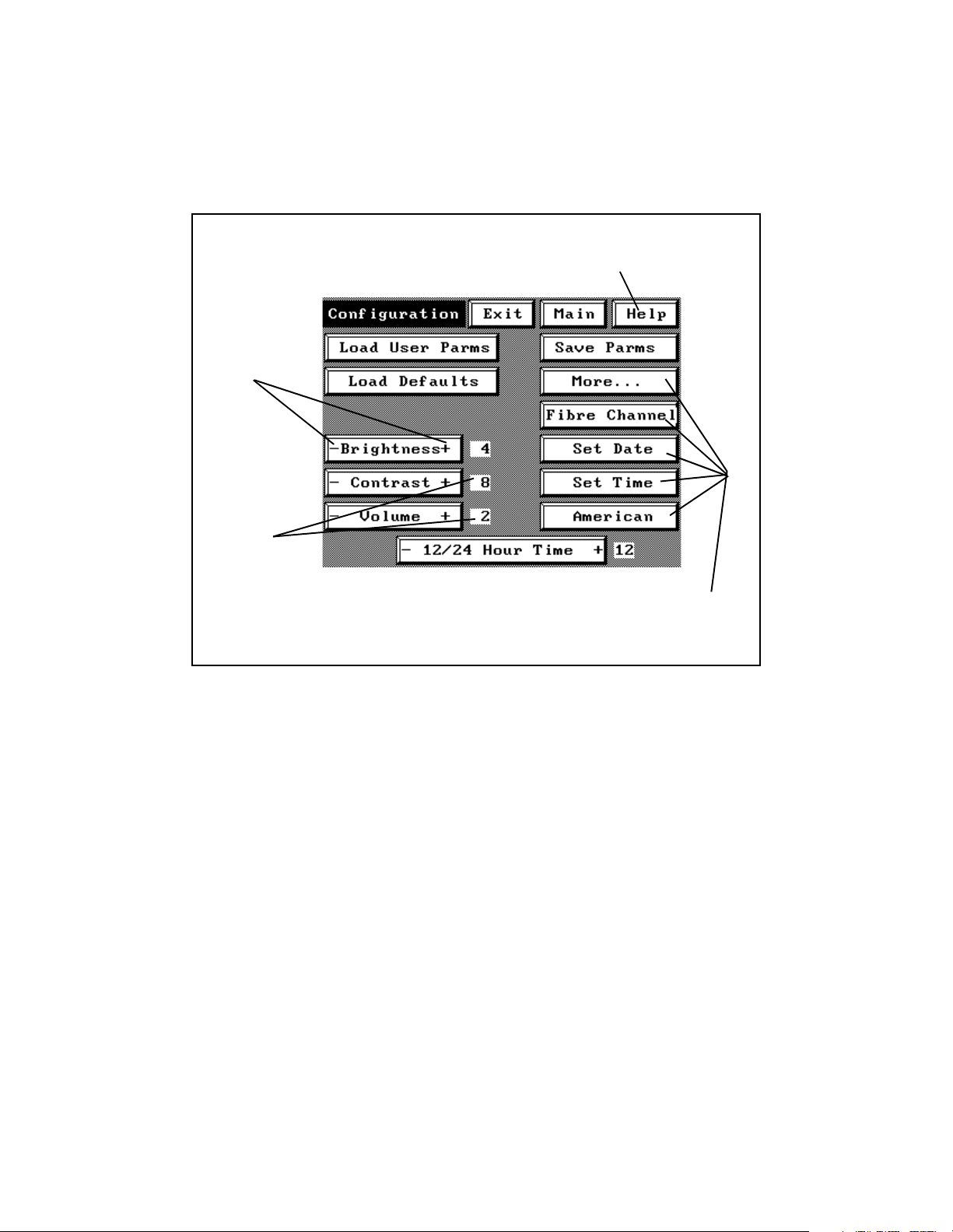
Library Menu Screens
Each menu screen on the library uses interactive buttons, like those shown below. You
can touch these buttons to view other screens or to change library settings.
Press Help to view online help for
the current screen.
Press the +
and - symbols
on buttons to
change
settings.
The
configured
setting is
displayed
beside the
button.
Press buttons to access other screens.
(Fibre Channel button on Fibre
Channel libraries only.)
Figure 1-1 The library’s interactive buttons (first Configuration screen).
Online help is available for all user screens, describing the controls and information
displayed on the screen from which you accessed the online help.
12
Page 13
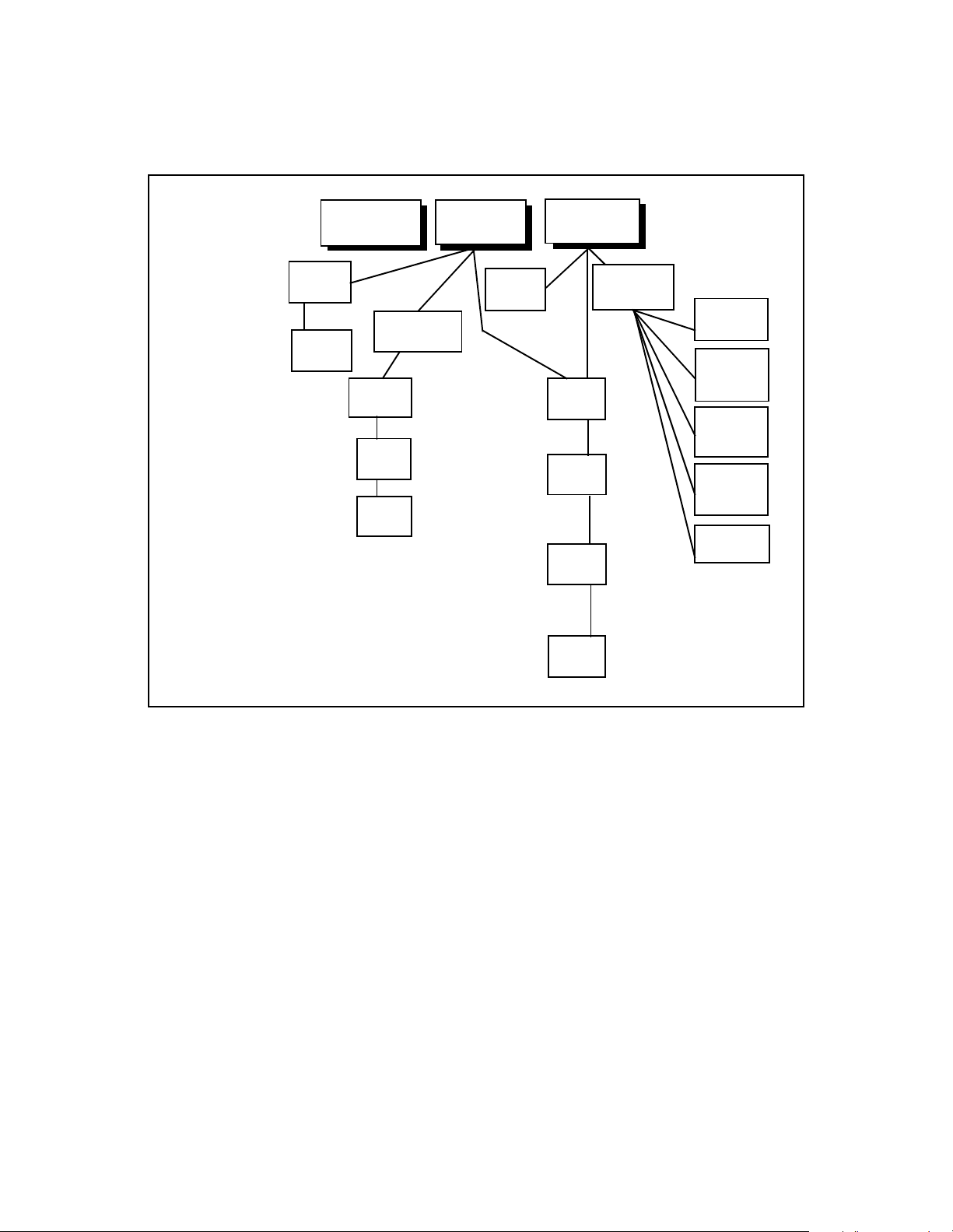
Chapter 1. Introduction
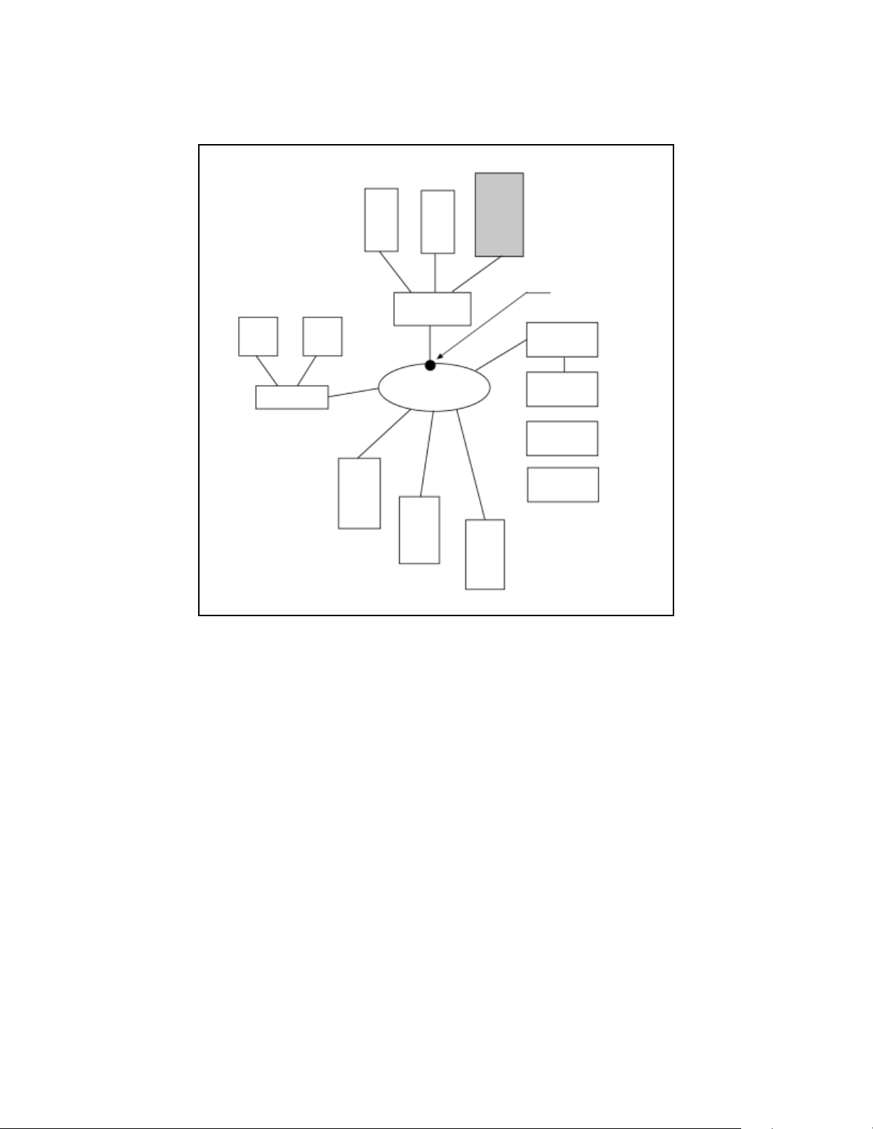
The overall structure of the menu screens is illustrated in the following diagram;
important settings are listed beside the screen from which they can be adjusted
.
SCSI ID
Model
Error Rates
Compre ssion
Serial Number
Rev Number
SCSI Bus Mode
Switch Override
Drive S/N
Spectra 10000
Drive Info
Screen 1
Drive Info
Screen 2
Move Tapes
Screen
Barcodes
Screen
ECC1
Screen
ECC2
Screen
Main Screen
MCE
Screen
Date
Time
Volu me
Brightness
Fibre Channel
RS232
Emulation
SCSI Initiator
ECC Fault Check
Queued Unloads
Library 2 Slots
SCSI Bus 2 ID
SCSI Bus Mode
Emulate 1/2
Emulate 3/4
Barcode Enable
Barcode Chksum
Autoread Barcodes
Menu Screen
Miscellaneous
Screen
Conf ig.
Screen 1
Conf ig.
Screen 2
Conf ig.
Screen 3
Conf ig.
Screen 4
Create Code
Tape Screen
Load
Firmware
Screen
View
Trace
Screen
Change
Password
Screen
Lock
Screen
Figure 1-2 Diagram of the library’s menu screens.
13
Page 14
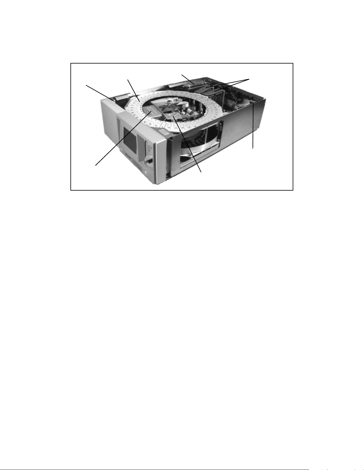
Internal Components
Chapter 1. Introduction
Lid sensor
Tape carou se l
Robotic
picker
Figure 1-3 The library’s internal components.
Power supply
Tape drives
UCM board
(SDC board)
(Fibre Channel board)
Bar code scanner
Tape Drives The library includes up to four Sony AIT tape drives, installed in the library
on customized Spectra Logic drive sleds.
Tape Carousel Depending on the size ordered at time of purchase, the fixed tape
carousel can store either 20 or 40 data cartridges when all four drives are installed.
(When fewer than four drives are installed, the unused drive slots become additional
tape cartridge slots.)
Robotic Picker The picker moves cartridges between tape slots, tape drives, and the
library door. The picker may also include a bar code reader, which scans bar code
labels on data cartridges.
Power Supply The power supply automatically detects the voltage and frequency of the
power source, either 110-volt or 220-volt AC, 50/60 Hz. The power cord shipped with
the library can handle either voltage.
UCM Board The UCM board is the library’s control center.
SDC Board Found only in HVD SCSI libraries, the single-ended to differential converter
(SDC) board translates SCSI signals from single-ended to differential format.
Fibre Channel Board Found only in Fibre Channel libraries, this board translates SCSI
signals to a flexible, high-speed Fibre Channel format.
14
Page 15
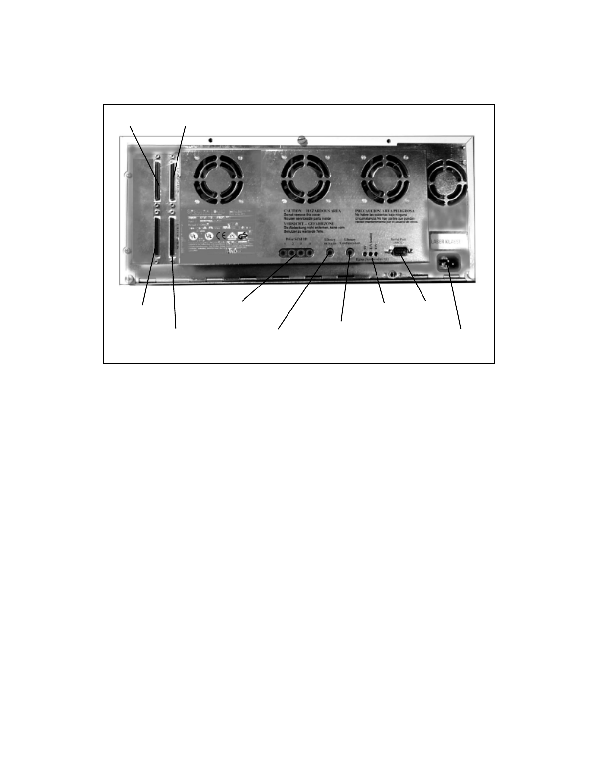
Chapter 1. Introduction
SCSI Library Rear Panel Components
SCSI Port 1 IN SCSI Port 1 OUT
SCSI Port 2 IN
SCSI Port 2 OUT
Figure 1-4 The SCSI library’s rear panel components.
Drive SCSI IDs
Library
SCSI ID
Library
Configuration
Fuse
lights
Serial
port
Power
connector
SCSI Ports The four SCSI ports enable you to connect the library as a device on a SCSI
bus, and attach terminators for proper device termination.
Drive SCSI IDs The SCSI ID switches control the SCSI IDs for installed tape drives. SCSI
ID settings for uninstalled tape drives are ignored by the library.
Library SCSI ID The library SCSI ID switch sets the SCSI ID for the library itself.
Library Configuration The library configuration switch determines the operating mode
of the library. The library configuration switch default setting is 0.
Fuse Lights There are three fuse lights, one for each fuse. When you need to replace
one of the library fuses, the appropriate fuse light will light up.
Serial Port The nine-pin serial port lets you connect a serial cable for diagnostics or
manual robotics control.
Power Connector The power connector provides a port for AC power.
15
Page 16
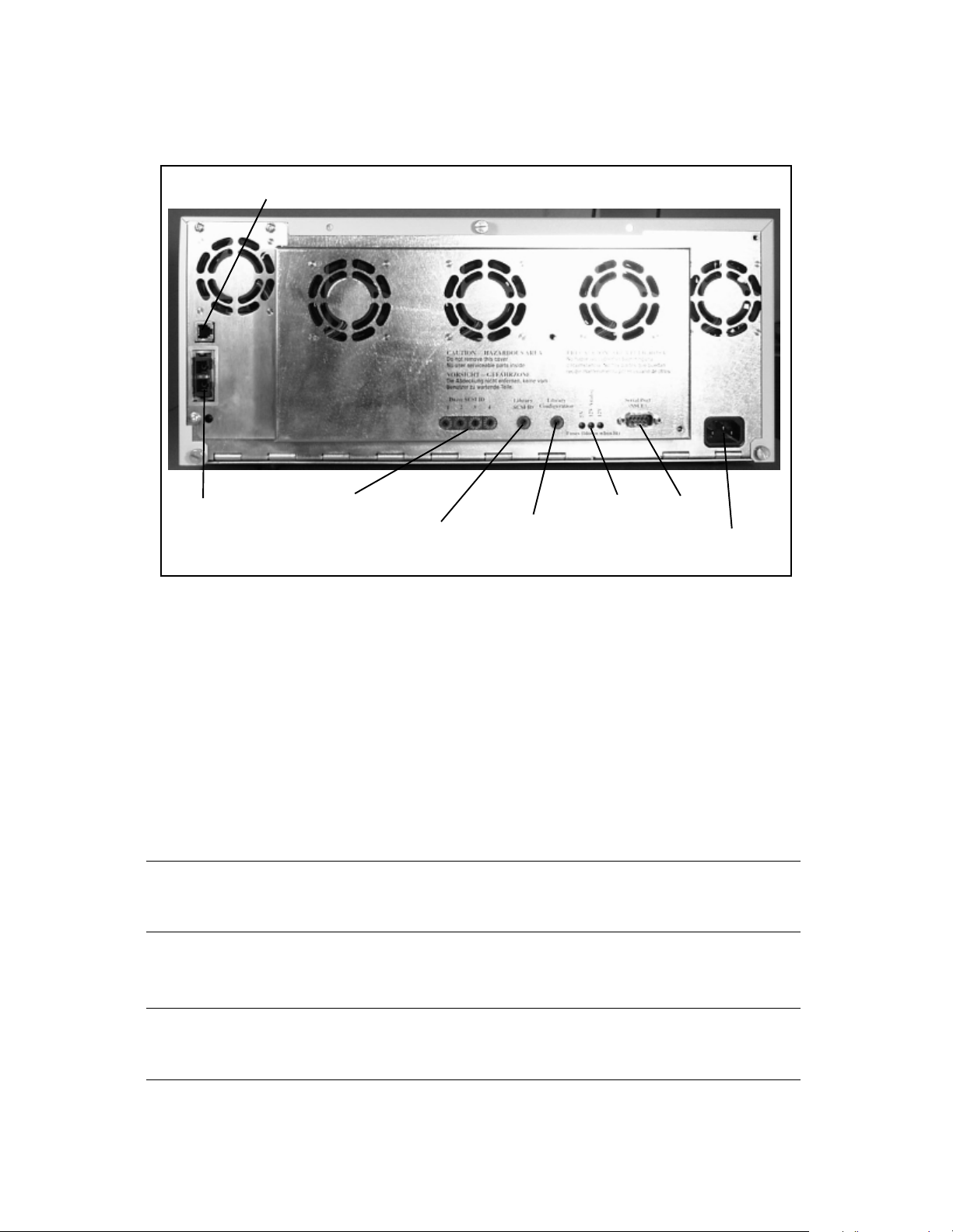
Chapter 1. Introduction
Fibre Channel Library Rear Panel Components
Ethernet port
Fibre
Channel
port
Figure 1-5 The Fibre Channel library’s rear panel components.
Drive SCSI IDs
Library
SCSI ID
Library
configuration
Fuse
lights
Serial
port
Power
connector
Fibre Channel Port The Fibre Channel port allows you to choose between three GBICs
for your library cabling.
Ethernet Port This port allows Spectra Logic support technicians to gain information
about your library.
Drive SCSI IDs The drive SCSI ID switches control the SCSI IDs for installed tape drives.
SCSI ID settings for uninstalled tape drives are ignored by the library.
Note: Do not change the default settings for the drives (2, 3, 4, and 5). If
the default settings are changed, the drives will not be recognized.
Library SCSI ID The library SCSI ID switch sets the SCSI ID for the library itself.
Note: Do not change default SCSI ID (6) for the library. If the default
setting is changed, the robotics will not be recognized.
16
Page 17

Chapter 1. Introduction
Library Configuration The library configuration switch determines the operating mode
of the library. The library configuration switch default setting is 0.
Fuse Lights There are three fuse lights, one for each fuse. When you need to replace
one of the library fuses, the appropriate fuse light will light up.
Power Connector The power connector provides a port for AC power.
17
Page 18
Chapter 1. Introduction
Storage Management Options
Following are a few examples of how the Spectra 10000 library can be used in different
storage management environments.
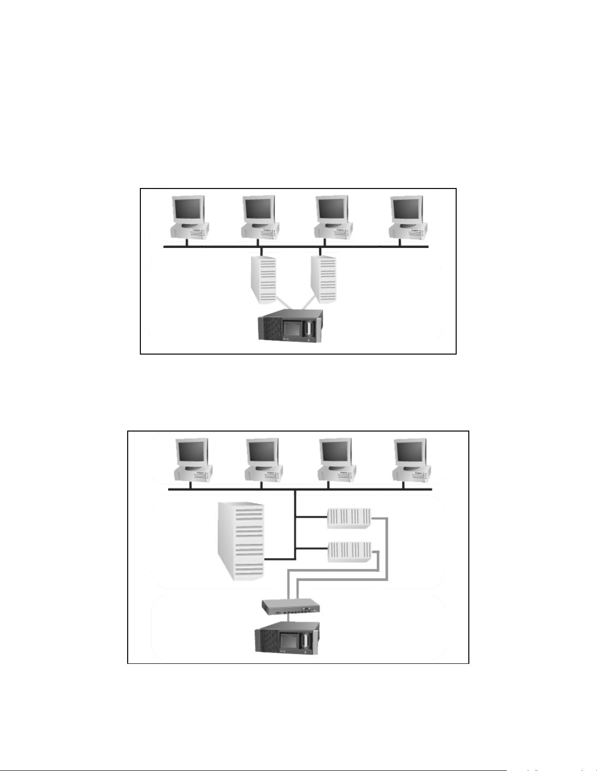
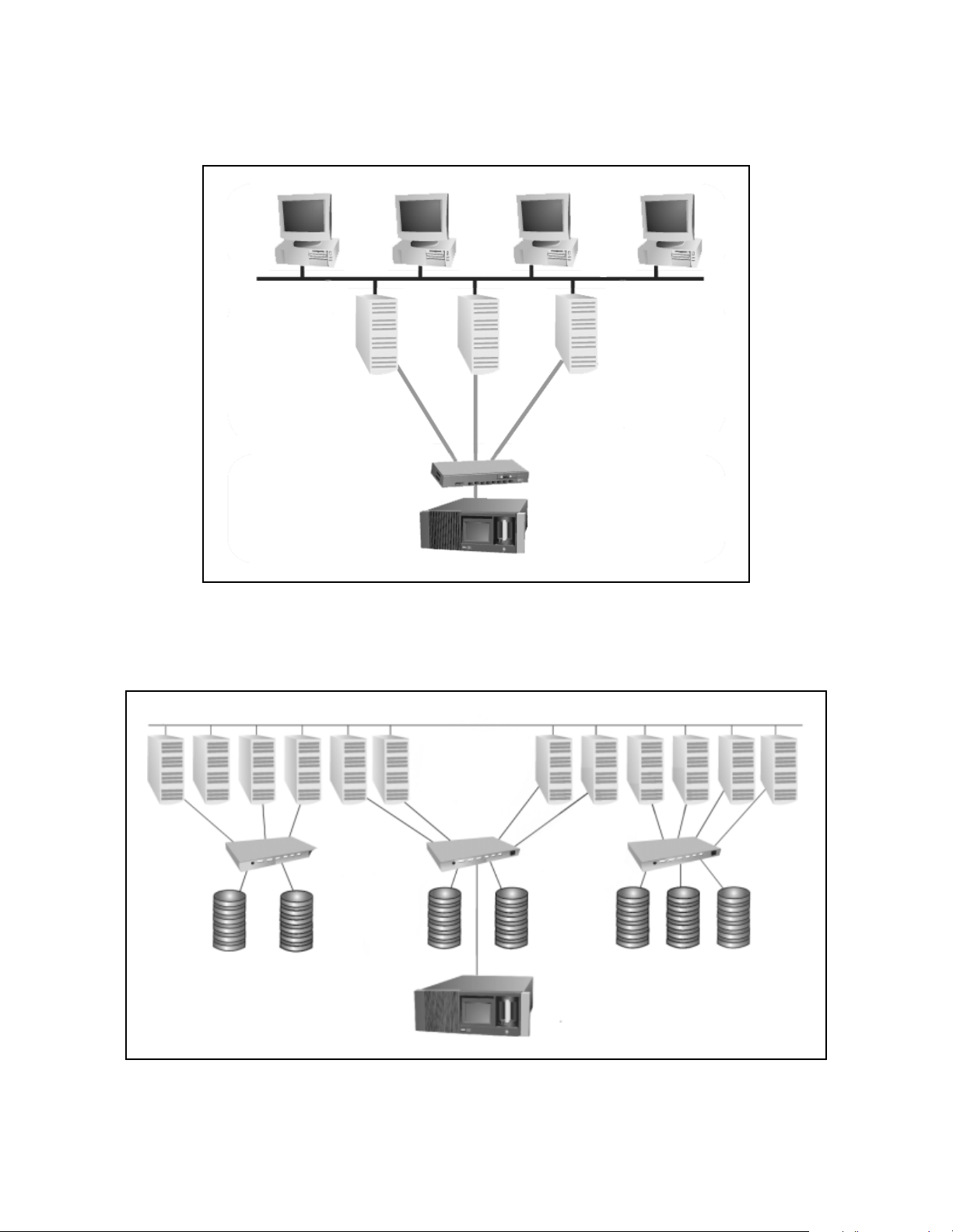
Direct Attached Storage (DAS) Environment
Clients
Servers
SCSI Library
Figure 1-6 A SCSI library in a DAS environment.
Network Attached Storage (NAS) Environment
Clients
Server
Fibre Channel
Switch
Filers
Fibre Channel
Library
Figure 1-7 A Fibre Channel library in a NAS environment.
18
Page 19
Chapter 1. Introduction
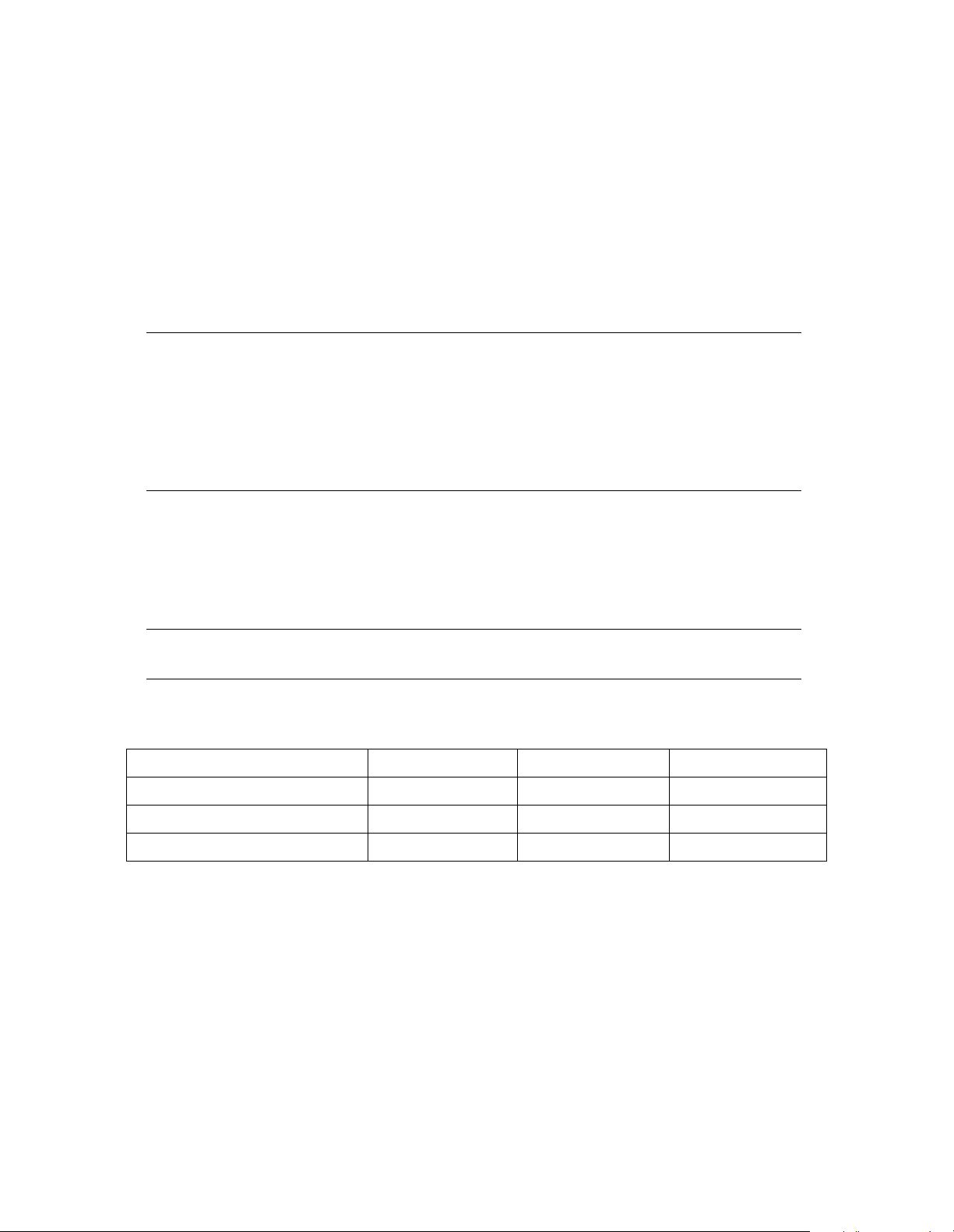
Storage Area Network (SAN) Environment
Clients
Servers
Fibre Channel
Switch
Fibre Channel
Library
Figure 1-8 A Fibre Channel library in one type of SAN environment.
LAN
Servers
Fibre Channel
Switches
Disk Arrays
Figure 1-9 A Fibre Channel library in another type of SAN environment.
19
Fibre Channel
Library
Page 20

Chapter 1. Introduction
Professional Services
Spectra Logic’s Professional Services group provides many services related to Spectra
Logic libraries. These services include installation, relocation, recertification,
consulting, training, maintenance, and more.
Professional Services can help you with new ways to use your library, or with
advanced solutions for your entire storage infrastructure. For more information about
Professional Services, contact your sales representative.
20
Page 21

2 Preparing the Host System
This chapter reviews the following operating system information:
• Selecting a SCSI Bus for the Library (SCSI Libraries Only)
• Determining SCSI ID Usage
• Sony AIT Device Driver Support
Before Configuring the Library
Before you begin configuring the library, you must prepare the host system you want
to use with your library. Preparing the host system may involve the following:
• Determining the SCSI bus on which host the library will be placed
• Determining which SCSI IDs are currently used by the host and any other attached
SCSI devices
• Adding device files for the library, tape drives or both
• Rebuilding the kernel (for some UNIX hosts)
Note: This guide does not include information on specific operating
systems. Refer to your operating system’s documentation for
installation instructions, or see the Server Preparation Document
for Spectra Logic Libraries, an online document located on the
Spectra Logic Web site at http://www.spectralogic.com/support/
index.cfm/fuseaction/displaySupportDocs/.
21
Page 22
Chapter 2. Preparing the Host System
Selecting a SCSI Bus for the Library (SCSI Libraries Only)
The single-ended/low-voltage differential (SE/LVD) library operates in either singleended or low-voltage differential SCSI mode, depending on the type of bus that is
attached. When attached to a single-ended SCSI adapter, it will operate within the
maximum specifications for that bus type.
Note: The entire bus (including host bus adapter, devices and
termination) must be configured for LVD operation in order to
operate in LVD mode. Attaching any single-ended SCSI device to
an LVD bus renders the entire bus (and all attached devices)
subject to the maximum specification requirements for
single-ended SCSI (including maximum cable lengths).
The terminator shipped with the SE/LVD library can function in either mode. To check
the mode in which your library is operating, look at the library terminator and the
terminator’s light-emitting diode (LED). The top of the terminator lists the color of the
LED for each mode.
Note: The HVD library includes an active HVD terminator.
SCSI specifications for LVD, SE, and HVD modes are shown in this table:
SCSI Specifications LVD Mode SE Mode HVD Mode
SCSI Bus Width 16 bits 16 bits 16 bits
Maximum Bus Speed 80 MB/sec 40 MB/sec 40 MB/sec
Maximum Bus Cable Lengths 12 meters
a
Maximum cable length requirements include the internal cabling for each device. (The library contains 60 centimeters [24 inches]
of cabling inside the library.)
a
1.5 meters
a
25 meters
a
Determining SCSI ID Usage
Each device on the SCSI bus to which the library is attached must have its own SCSI
ID. Examine your host system and attached devices to determine which SCSI IDs are
22
Page 23

Chapter 2. Preparing the Host System
already in use, and which SCSI IDs are still available. The library requires one SCSI ID
for each installed drive, as well as a SCSI ID for the library itself.
Sony AIT Device Driver Support
Spectra Logic, working with Sony, has performed system compatibility testing to
ensure operability on most popular operating systems and hardware platforms. On
many platforms, the Spectra 10000 library and Sony AIT drives will function using the
standard device drivers used for other 8mm drives and libraries.
Operating System Compatibility
Some operating system and hardware platforms do not support the Sony AIT tape
drives with standard device drivers. For these instances, Spectra Logic Technical
Support will provide you with detailed installation procedures that will allow the
system to function properly.
Software Compatibility
The Spectra 10000 library is natively supported by most third party software
applications. Current software compatibility information can be found on the Spectra
Logic Web site at http://www.spectralogic.com/support/index.cfm/fuseaction/
displayCompatibility/.
If You Need Assistance
If you have questions regarding your library, drives, operating system, software, or
drivers, you can find most of your answers in the Technical Support Knowledge Base,
located on the Spectra Logic Web site at http://www.spectralogic.com/support/kbase/
index.cfm/.
23
Page 24

Chapter 2. Preparing the Host System
24
Page 25

3 Preparing the Library
Preparing the library includes the following, which are outlined in this chapter:
• Unpacking the Library
• Selecting an Appropriate Environment for the Library
• Selecting the Mode of Library Operation
• Setting SCSI IDs
• Setting the Library Configuration Switch
• Connecting the SCSI Cables and Terminators
• Connecting the Serial Cable
• Connecting the Library to Fibre Channel
• Connecting the AC Power
Unpacking the Library
The Spectra 10000 library is shipped with the following items:
• Spectra 10000 Library Release Notes
• Spectra 10000 Library User Guide (this guide)
• One Spectra Logic screwdriver
• One AC power cord
• Two SCSI terminators (for SCSI libraries only)
• One front panel filter element
Note: Keep the library’s shipping carton and foam inserts. If the library
needs to be shipped for any reason, it must be packaged in its
original box and packing material for the warranty to remain valid.
See Packing the Library for Shipment on page 89 for information
on the correct way to repackage the library.
See the Spectra Logic Repair Policy on page 106 for information on
returning a library for service.
25
Page 26

Chapter 3. Preparing the Library
Selecting an Appropriate Environment for the Library
Media and Hardware Environment
When planning the installation of your library, note that the library, drives and media
must be maintained in a controlled environment. Environmental extremes cause erratic
operation and possible failures. Choose an environmentally controlled location that is
free of smoke and dust. Choose a location that is also temperature and humidity
controlled.
Handle the library with the same care you would use with any computer or computer
peripheral equipment. If the library is mounted in a rack, be sure that the temperature
in the rack does not exceed the maximum ambient operating temperature of the library
and that the library is well ventilated with adequate air flow at all times.
Library operating specifications are:
• Temperature: 41°F to 86°F (5°C to 30°C)
• Relative humidity: 20 percent to 80 percent (non-condensing)
• Maximum wet bulb temperature: 77°F (25°C)
Caution: Before using any new media, condition the data cartridges by
allowing the cartridges to reach ambient temperature for a time
at least equal to the period during which it has been out of the
operating environment (up to a maximum of 24 hours).
See Sony AIT Tape Drive Specifications on page 113 and Sony AIT Media Specifications
on page 116 for additional information on drives and media.
26
Page 27
Chapter 3. Preparing the Library
Air Quality
Large quantities of airborne particles cause erratic operation of the drives and library.
The library comes with an intake air filter behind the front panel to reduce the amount
of airborne particulates entering the library.
The table below shows the maximum amount of particulate contamination per cubic
foot and cubic meter of air which the library’s filter can handle. If you are exceeding
these limits, filter the air in the room where you are using the library.
Number of Particles
Particle Size
0.1 microns 2.5 x 10
0.5 microns 1.0 x 10
5.0 microns 7.0 x 10
≥ Particle Size per Cubic Foot ≥ Particle Size per Cubic Meter
6
6
3
8.8 x 10
3.5 x 10
2.5 x 10
7
7
5
Rack Mount vs. Tabletop Configuration
The standard library configuration uses a 17-inch tabletop chassis. An optional rack
mounting kit is available, using faceplate extenders which extend beyond the width of
the standard front panel and cover the mounting ears on the library and the side rails
of the mounting rack.
Spectra Logic offers a rack mount upgrade kit that allows a user to convert a tabletop
library to either a white or black rack mount library. Contact your sales representative
for more information about these kits.
Installing in Enclosed Equipment Racks To use an enclosed rack for the library, you need
an enclosed rack mount model or an enclosed rack mount conversion kit. To identify
models compatible with enclosed racks, compare the part number from the library’s
serial number sticker (located on the back of the library) to the part number shown
below. Make sure that your library’s serial number contains an M or a 3 in the last
position (shown here).
9284AXXX-X-XM or 9284AXXX-X-X3
An M shown in the part number indicates a white enclosed rack mount model, and a 3
indicates a black enclosed rack mount model.
Spectra Logic offers an enclosed rack mount upgrade kit that allows a user to convert a
non-compatible library for both white and black enclosed rack mount models. Contact
your sales representative for more information about these kits.
27
Page 28

Chapter 3. Preparing the Library
Preparing to Connect the Library
Before connecting the library to the host system, you must prepare the library by
completing the following steps:
1. Select the mode of library operation. See Selecting the Mode of Library
Operation on page 29.
2. If a SCSI interface library, set the library SCSI IDs, or, if a Fibre Channel
interface library, set the library for soft or hard addressing. See Setting SCSI IDs
on page 36.
3. Set the library configuration switch. See Setting the Library Configuration
Switch on page 38.
4. Connect the appropriate cables, terminators, or GBICs. See Connecting the SCSI
Cables and Terminators on page 39, Connecting the Serial Cable on page 40,
and/or Connecting the Library to Fibre Channel on page 41.
5. Connect AC power to the library. See Connecting the AC Power on page 43.
28
Page 29

Chapter 3. Preparing the Library
Selecting the Mode of Library Operation
A SCSI library can operate in either single-bus or dual-bus mode.
Note: The following information on single-bus and dual-bus libraries
only applies to SCSI libraries.
For more information on SE/LVD libraries, see Selecting a SCSI Bus
for the Library (SCSI Libraries Only) on page 22.
Single Bus Mode
If you want to use only one host with one SCSI controller, operate the library in either
one of these single-bus configurations:
Option Settings SCSI Cabling
If you have a
single-ended library
with one to two drives.
If you have a
differential library
(HVD or LVD) with three
to four drives.
If the library is the last device on the SCSI bus, connect terminators to the SCSI output
connectors. If the library connects to another SCSI device, connect the SCSI cable from
the output of the library to the next SCSI device. Terminate the SCSI output of the final
device on the SCSI bus.
If you have decided to operate in single-bus mode, the next step is to set the library
SCSI ID. See Setting SCSI IDs on page 36.
Set the rear panel Library SCSI ID
switch to a unique ID.
Set the SCSI Bus 2 ID setting to OFF.
Set the rear panel Library SCSI ID
switch to a unique ID.
Set the SCSI Bus 2 ID setting to OFF.
Terminate SCSI Port 1 Out.
Attach host SCSI cable to SCSI Port 1 In.
Ensure that drives are installed in Drive Slots 1 and 2.
Use the six-inch external SCSI link (P.N. 4531) to connect
SCSI Port 1 Out to SCSI Port 2 In.
Attach host SCSI cable to SCSI Port 1 In.
Terminate SCSI Port 2 Out or attach a SCSI cable to the
input of another SCSI device.
Note: If you have a single-ended library with three or four installed
drives, you must operate the library in dual-bus mode. See The
SCSI Bus on page 118 for details on SCSI bus lengths.
29
Page 30

Chapter 3. Preparing the Library
Dual Bus Mode
If you want to use two hosts, or if you have a library (either single-ended or
differential) with three or four installed drives and want the fastest transfer rate
possible, operate the library in either of these dual-bus configurations:
Option Settings SCSI Cabling
If you have a
single-ended or
differential library and
want to use one host...
If you have a
single-ended or
differential library and
want to use two hosts
(dual logical library
operation)...
If the library is the last device on the SCSI bus, connect terminators to the SCSI output
connectors. If the library connects to another SCSI device, connect the SCSI cable from
the output of the library to the next SCSI device. Terminate the SCSI output of the final
device on the SCSI bus.
Set the rear panel Library SCSI
ID switch to a unique ID.
Set the SCSI Bus 2 ID setting to
to a unique ID.
Set the rear panel Library SCSI
ID switch to a unique ID.
Set the SCSI Bus 2 ID setting to a
unique ID.
Configure Library 2 slots setting.
Terminate SCSI Port 1 Out.
Attach Host A SCSI cable to SCSI Port 1 In.
Terminate SCSI Port 2 Out.
Attach Host A SCSI cable to SCSI Port 2 In.
The host must have two SCSI controller cards—one for each
input.
Terminate SCSI Port 1 Out.
Attach Host A SCSI cable to SCSI Port 1 In.
Logical Library 1 has exclusive rights to Drives 1 and 2 on SCSI
Port 1.
Terminate SCSI Port 2 Out.
Attach Host B SCSI cable to SCSI Port 2 In.
Logical Library 2 has exclusive rights to Drives 3 and 4 on SCSI
Port 2.
Note: It is possible to connect 8-bit (narrow) SCSI devices to the 16-bit
(wide) SCSI connectors on the library, as long as the library is the
first device after the host on the SCSI bus.
Adapters are available that terminate the upper eight bits of the
wide SCSI bus and interface 68-pin micro-SCSI connectors to 50pin SCSI connectors (see SCSI Cables and Terminators on page
119).
See The SCSI Bus on page 118 for details of SCSI bus configuration.
If you have decided to operate the library in dual-bus configuration with two hosts, see
Split-Bus Configuration on page 31.
30
Page 31
Chapter 3. Preparing the Library
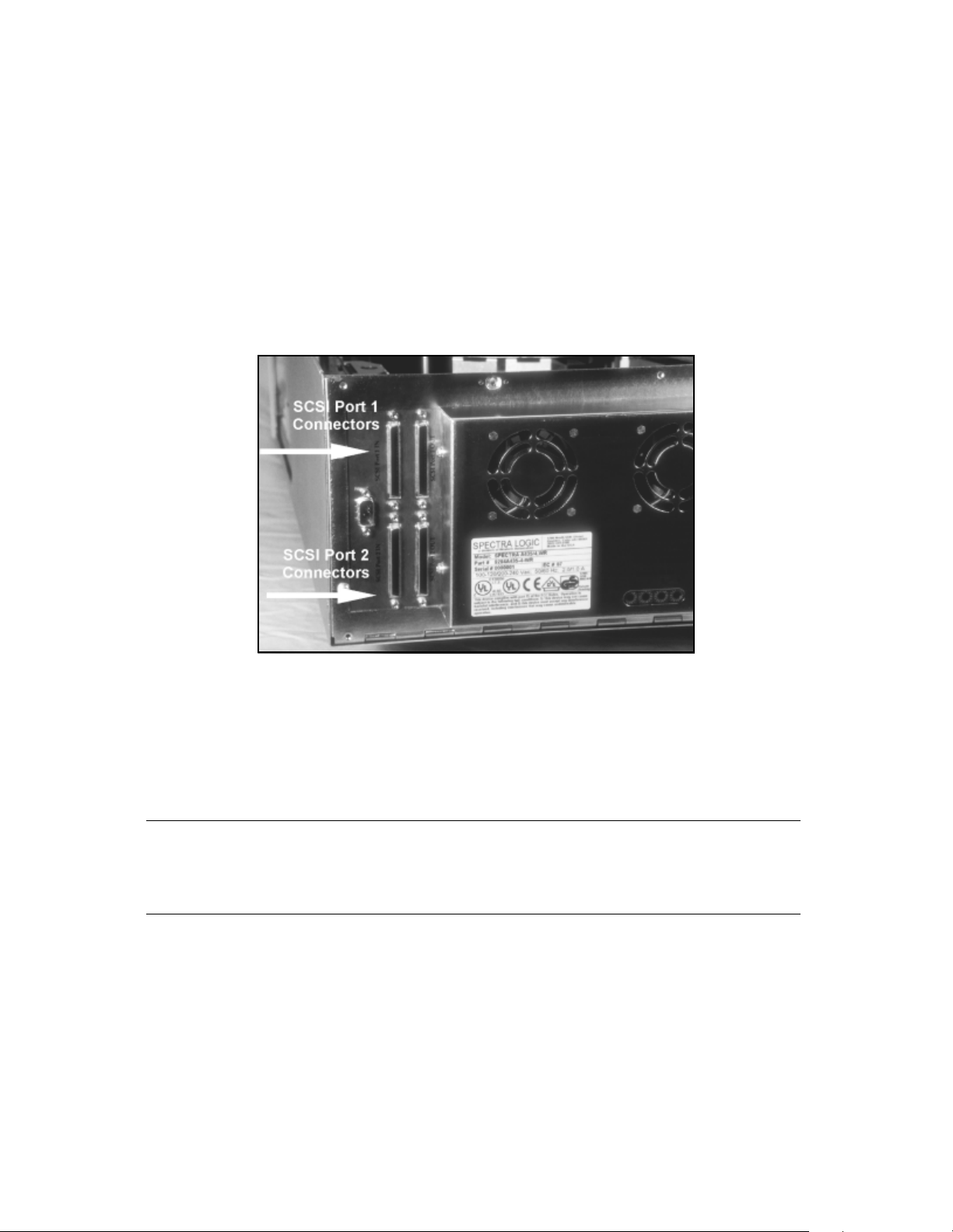
Split-Bus Configuration
The library firmware version 5.00 (and later) has the ability to logically split the library
into two separately addressable logical library systems. This feature allows two host
machines to share the same library hardware. Slots can be split on boundaries of 10.
The tape drive split occurs on the SCSI bus boundary. The D1 and D2 (SCSI Port 1)
drive positions belong to Logical Library 1. The D3 and D4 (SCSI Port 2) drive
positions belong to Logical Library 2. If each logical library is to have a single tape
drive connected, they need to be installed in drive positions D1 and D3.
Figure 3-1 SCSI connectors for Port 1 and Port 2.
The split library feature is supported with both serial and SCSI robotics command
interfaces; you can have both hosts issue commands to each logical library via SCSI
connections, or have one host issue commands to logical Library 1 via a serial port
connection and one host issue commands to logical Library 2 via a SCSI connection.
Caution: For a split logical library with only two drives, install the tape
drives in the first and third drive positions, or the library will not
function correctly.
To enable split bus configuration and configure the number of slots for each logical
library, follow this procedure:
1. From the main screen, press CONFIG > MORE > MORE. The third Configuration
screen appears.
The Library 2 Slots and SCSI Bus 2 ID settings determine the logical library
configuration.
31
Page 32

Chapter 3. Preparing the Library
By default, the Library 2 Slots is set to Off for no split logical library operation
(Figure 3-2).
Figure 3-2 With Library 2 Slots set to off (the default position)
the library is configured as one logical library.
2. Using the Library 2 Slots field, set the number of slots devoted to the second
logical library.
Tape storage slots are assigned in multiples of 10, so the Library 2 Slots will
need to be set to 10, 20, or 30 (for 20-slot libraries, the only option is 10).
Slots not allocated to the second logical library are automatically allocated to the
first logical library.
3. Set the SCSI Bus 2 ID to a unique number on the second SCSI bus.
This ID will need to be set to a SCSI ID different from the other devices
connected to the SCSI Port 2 connection.
4. To save the changes, press SAVE PARMS.
A message displays: PARAMETERS SAVE, RESTART?
5. Select YE S . The library restarts with the new configuration settings.
6. To set the drive emulation settings, read Configuring Library Tape Drive Settings
on page 54.
32
Page 33

Chapter 3. Preparing the Library
Managing the Split-Bus Configuration
A split logical library appears to the host system as two independent physical libraries.
In the example below, the library is configured as two logical libraries, where Logical
Library 2 has 10 slots and its SCSI ID is set to 5.
The SCSI ID
for Logical
Library 2 is
set to 5.
Logical Library 2
is allocated 10
slots.
The remaining
slots in the
library are
allocated to
Logical Library 1.
Figure 3-3 Configuring a library for split-bus mode.
To identify the slots associated with the two logical libraries, the Move Tapes screen
shows a blank row between the slots assigned to each library. In the screen shown
below, slots 1-30 are assigned to Logical Library 1 (SCSI Port 1) and slots 31-40 are
assigned to Logical Library 2 (SCSI Port 2).
Slots allocated
to Logical
Library 1
(SCSI Bus 1)
Slots allocated
to Logical
Library 2
(SCSI Bus 2)
Figure 3-4 The Move Media screen changes in split-bus mode.
Slots allocated
to Logical
Library 2
(SCSI Bus 2)
are separated
from slots
allocated to the
first library.
Physical slot numbers retain the original numerical sequence on the front panel
interface. In this example, the slots in Logical Library 2 are mapped as 1-10 to the host
system, but mapped as 31-40 on the Move Media screen.
33
Page 34

Chapter 3. Preparing the Library
As explained above, each logical library has a separate SCSI bus, separate drives, and
separate slots. The following diagrams illustrate different logical library configurations.
Possible Logical Library Configuration 1 In the example below, a four-drive, 40-slot library
is connected to two machines. Each host is allocated 20 tape slots and exclusive rights
to two tape drives each. A SunOS host machine runs Veritas software with 20 slots and
two drives on SCSI Bus 1; an HPUX host machine running Veritas is allocated the
remaining 20 tape slots and two drives on the second SCSI bus. The Emulate 1/2 field
is set to 10 (Sun running Solaris) and the Emulate 3/4 field is set to 13 (HP9000
running HPUX).
Drive 1
SCSI Bus 1
Drive 2
SunOS Host
SCSI Bus 2
HPUX Host
Figure 3-5 Possible Logical Library Configuration 1.
20 Slots
20 Slots
Drive 3
Drive 4
34
Page 35

Chapter 3. Preparing the Library
Possible Logical Library Configuration 2 In the example below, the division of slots is not
equal between host machines. In this example, a UNIX host running Legato is allocated
two tape drives and 30 slots; a Windows NT machine running Legato is allocated the
remaining 10 tape slots and two tape drives.
SCSI Bus 1
UNIX Host
SCSI Bus 2
Windows NT Machine
Figure 3-6 Possible Logical Library Configuration 2.
Drive 1
Drive 2
30 Slots
10 Slots
Drive 3
Drive 4
35
Page 36

Chapter 3. Preparing the Library
Setting SCSI IDs
First, make sure that the library power is off, then set the library on a work surface
with the rear panel facing you.
Note: The following SCSI ID information only applies to SCSI libraries.
The ID switches on Fibre Channel libraries are preset at the factory
and should not be changed.
Drive SCSI IDs
SCSI ID switches 1 through 4 correspond to the numbered location of the drives in the
library. There are 16 positions for each switch, 0h to Fh, corresponding to 16 possible
SCSI IDs. When setting the tape drive SCSI IDs, note the following:
• Each item on a SCSI bus must have a unique SCSI ID. In dual bus mode, two drives
may have the same SCSI ID if the drives are on different busses.
• If the drive slot is empty, the library ignores the SCSI ID.
Setting the Drive SCSI IDs
Using the Spectra Logic screwdriver included with the library, turn the drive SCSI ID
switches for each installed drive until the arrow on the switch indicates the SCSI ID
you want.
Caution: Identify the SCSI IDs currently in use and determine which SCSI
IDs are available for use with the library and drives. Conflicting
SCSI IDs can cause the system to fail.
36
Page 37

Chapter 3. Preparing the Library
Library SCSI ID
In both single and dual bus mode, the Library SCSI ID switch on the rear panel
determines the SCSI ID for SCSI Bus 1.
In Single-Bus Mode With the library power off, set the SCSI ID for Bus 1 using the
Library SCSI ID switch, then power the library on, and check that the SCSI Bus 2 ID is
set to off (the factory default). The SCSI Bus 2 ID setting is on the third Configuration
screen.
In Dual-Bus Mode With the library power off, set the SCSI ID for Bus 1 using the Library
SCSI ID switch, then power the library on, and set the SCSI Bus 2 ID setting to a
unique SCSI ID. The SCSI Bus 2 ID setting is on the third Configuration screen.
Note: Dual bus units are shipped with SCSI Bus 2 disabled and Drive 3
and Drive 4 will report FAULT until the bus is configured for your
system. Set SCSI Bus 2 ID in the third Configuration screen to an
appropriate setting for the SCSI cable connected to SCSI Bus 2.
Likewise, if the library is in the dual-bus mode and SCSI ID 2 is set
incorrectly, the library will power up with an error until the second
SCSI bus ID is properly configured.
Setting the Library SCSI ID for Bus 1
Using the Spectra Logic screwdriver included with the library, turn the library SCSI ID
switch until the arrow on the switch indicates the SCSI ID you want.
37
Page 38

Chapter 3. Preparing the Library
Setting the Library Configuration Switch
With the library off, use the Spectra Logic screwdriver to set the configuration switch.
The library configuration switch determines the operating mode of the library. The
table below outlines the mode for each switch setting.
Note: Do not change from the default setting (0) unless instructed to do
so by Spectra Logic support personnel.
Config Switch Mode and Description
0 (default) Standard Operation, SCSI Parity Enabled
1 Standard Operation, SCSI Parity Disabled
2 SCSI Target Mode Disabled (SSCL Only)
3 Reserved
4 Reserved
5 Reserved
6 Reserved
7 Force Firmware Upgrade
Turn the library on to have the configuration switch setting change take effect.
Note: See Forcing a Firmware Reload on page 70 before setting the
configuration switch to position 7.
38
Page 39

Chapter 3. Preparing the Library
Connecting the SCSI Cables and Terminators
Four 68-pin micro-SCSI connectors on the rear panel connect the library to the system
SCSI busses. The SCSI connectors are labeled SCSI Port 1 (IN and OUT) and SCSI Port
2 (IN and OUT).
Note: Make sure to review The SCSI Bus on page 118 before connecting
your library.
To attach SCSI connections between the library and the host:
1. Attach the SCSI cable to the library (a dual bus library requires two SCSI cables).
2. Terminate the SCSI bus with a SCSI terminator (or two SCSI terminators if you
are configuring the library as a dual bus library).
Note: All SCSI busses must be terminated at the output of the final SCSI
device on the bus (see SCSI Cables and Terminators on page 119).
39
Page 40

Chapter 3. Preparing the Library
Connecting the Serial Cable
Most backup software packages do not require a serial connection between the library
and the host.
• With the SSCL interface, you will need both serial and SCSI connections between
the host and the library.
• Using SCSI pass-through drivers, you will only need a SCSI connection between the
host and your library (see SCSI Cables and Terminators on page 119).
If the backup software you are using requires a serial connection, attach a serial cable
between the library and the host computer. The DB-9 end of the cable connects to the
library’s RS-232 serial port, and the other end connects to a serial port on the host.
Note: If used, the serial port on the host must be dedicated to the library;
disable all serial port processing programs running on this serial
port.
Also, if hardware handshaking (see RS-232 Handshake on page
49) is enabled on the library, it must also be enabled on the host
serial port. Consult your host documentation for information on
configuring serial ports.
40
Page 41

Chapter 3. Preparing the Library
Connecting the Library to Fibre Channel
Consult the documentation for your host operating systems and Fibre Channel adapter
cards for information on adding new devices. In particular, look for details on creating
and configuring device files or drivers, and whether your system must be restarted
before using new devices.
To connect the library, insert the cable into the GBIC port on the rear of the library
(Figure 3-7).
GBIC
connection
location
Figure 3-7 Rear panel of the library, showing the GBIC connector for data communication.
The library can have one of three different kinds of GBICs, shown below with their
corresponding cables and connectors.
Figure 3-8 Optical cable
and SC connector.
Figure 3-9 Copper cable
and DB-9 connector.
41
Figure 3-10 Copper cable
and HSSDC connector.
Page 42

Chapter 3. Preparing the Library
The library supports arbitrated loop topology with various methods of connectivity.
Connect the other end of the cable according to your Fibre Channel connectivity as
directed in the table below and in Figure 3-11, Figure 3-12 and Figure 3-13.
Loop Connectivity Description Connect the library to...
Private loop Library and computer(s) are connected directly to each
other (direct device-to-device loop) or through a hub
(standalone loop).
Public loop The library is connected to fabric via an FL port, either
direct or via a loop.
Spectra 10000
Server
Library
Figure 3-11 Two-node private loop.
The Fibre Channel adapter in the host
computer or to an available port on the
hub.
An available port on the hub.
Server
1
Wor ks tat ion
Figure 3-12 N-node private loop.
Hub
Server
2
Disk
Array
Spectra
10000
Library
42
Page 43
Chapter 3. Preparing the Library
System Cluster
Hub
Storage Cluster
Spectra
10000
Library
FL Port
Hub
Bridges
Fabric (Switch)
Legacy
Storage
Servers
Figure 3-13 N-node public loop.
Connecting the AC Power
Connect the AC power cord supplied with the library to the AC connector on the rear
of the library. Connect the other end to a 110-volt or 220-volt AC, 50/60 Hz outlet.
The host system must be configured for the library, and the library and all SCSI
peripheral devices must be powered up and ready before you power up and boot the
host system.
43
Page 44

Chapter 3. Preparing the Library
44
Page 45

4 Configuring the Library
After you have prepared and connected the host and the library, you are ready to
power up the library and configure the library settings using the touch screen display.
This chapter describes the following:
• Configuring Library Software
• Setting Library Parameters
• Configuring Library Tape Drive Settings
• Checking for Correct Operation
Configuring Library Software
Selecting the Library Mode
If you configured the library to operate in dual-bus mode, you must configure the SCSI
Bus 2 ID setting using the front panel.
SCSI Bus 2 ID
The default setting for SCSI Bus 2 ID is OFF. Leave this setting off in either of these two
situations:
• Both internal SCSI busses are linked with an external cable (differential SCSI
libraries only).
• Two tape drives are installed in the library and both are connected to SCSI Bus 1
(Positions 1 and 2 in the library).
To set the SCSI ID for the second SCSI bus:
1. Power off the host system, all peripheral equipment, and the library.
2. Disconnect the library SCSI cables and terminate the two SCSI OUT ports.
3. Power on the library and wait for the main screen to appear.
4. From the main screen, press Config > More > More. The third Configuration
screen appears.
The current SCSI Bus 2 ID setting is displayed next to the SCSI Bus 2 ID button.
45
Page 46

Chapter 4. Configuring the Library
5. Touch the + and - symbols next to the SCSI Bus 2 ID button to scroll through
the SCSI IDs and select the appropriate setting.
6. Touch Save Parms > Yes
7. Power off the library and reconnect the system SCSI cables.
8. Power on the library, and, after it comes ready, turn on any other peripheral
equipment and confirm proper operation of the system.
to restart the library and save changes.
Note: If the library is in the dual SCSI mode (SCSI busses are not
connected with the SCSI link) and SCSI ID 2 is off, Drive 3 and
Drive 4 will power up with an error until the second SCSI bus ID is
properly configured.
Split-Bus Operation Only: Library 2 Slots
If you configured the library to be shared by two hosts (as two logical libraries), as
discussed in Selecting the Mode of Library Operation on page 29, you must configure
the Library 2 Slots setting.
Library 2 Slots Defines the slots for the second logical library, allocated in multiples of
10. If you have only configured the library to use one host, leave this setting off.
• Touch the + and - symbols to enable or disable slots, depending on whether you
have configured a second logical library.
• Touch Save Parms > Yes to restart the library and have the changes take effect.
46
Page 47

Chapter 4. Configuring the Library
Setting Library Parameters
Set the library’s operating parameters by using the four library configuration screens.
In these screens, at any point, you can:
• Touch Load Defaults to load factory preset settings for all parameters.
• Touch Load User Parms to reload the last saved parameters, or touch Save Parms to
store changes in the non-volatile memory.
Ensure that the library is idle before saving parameters. When you touch Save Parms,
an interactive information box appears asking if you want to restart the library. Most
parameter changes take effect immediately, so it is not necessary to restart the library,
unless you change:
• SCSI IDs
• Emulations
•Bar code settings
• SCSI Bus 2 ID
• Library 2 slots
Note: Parms are the user-defined configuration parameters. The Save
Parms, Load Defaults and Load User Parms
saving a new parameter saves all current parameters.
options are global;
General Settings
The following General Settings options are set from the library configuration screens:
• Brightness, contrast, and volume
• Date and time
• Library emulation
• RS-232 handshaking
• SCSI initiator and SCSI bus mode
47
Page 48

Chapter 4. Configuring the Library
Brightness, Contrast, and Volume
Set the front panel’s brightness, contrast, and volume from the first Configuration
screen. To access this screen from the main screen, press Config.
To set the brightness, contrast, or volume:
• Touch the + symbol on the right side of the Brightness, Contrast, or Volume buttons
to increase the setting, or touch the - symbol on the left side of the button to
decrease the setting.
• Touch Save Parms > No,
changes to take effect.
because it is not necessary to restart the library for these
Date
Set the front panel’s date from the first Configuration screen. To set the date from the
main screen, press Config.
Note: This procedure sets only the date displayed on the library’s front
panel; it does not affect any date settings used by the host or
backup software.
To set the date:
1. Touch the Set Date button on the first configuration screen.
2. Enter a two-digit number, between 0 and 99, for the current year, then touch OK.
3. Enter the current month, between 1 and 12, then touch OK.
4. Enter the current day, between 1 and 31, then touch OK.
5. Touch Save Parms > No, because it is not necessary to restart the library for these
changes to take effect.
American/European The American/European button toggles between the two styles of
date format:
• The American format is month/day/year. The European format is day/month/year.
• Touch Save Parms > No, because it is not necessary to restart the library for these
changes to take effect.
48
Page 49

Chapter 4. Configuring the Library
Time
Set the time from the first Configuration screen. To get there from the main screen,
press Config. This procedure sets only the time the displayed on the library’s front
panel; it does not affect any time settings used by the host or backup software.
To set the time:
1. Press the + or - symbols on either side of the 12/24 Hour Time button,
depending on the format in which you want the time displayed. The enabled
setting of 12 or 24 appears next to the button.
2. Press the Set Time button. The Set Time dialog appears.
3. Enter the hour (a number between 0 and 23, depending on whether you have
chosen 12-hour or 24-hour time), then touch OK.
4. Enter the minutes (a number between 0 and 59), then touch OK.
5. Enter the seconds (a number between 0 and 59), then touch OK.
6. Touch Save Parms > No; the changes are saved without restarting the library.
Note: Touch Back to backspace over an entered number. Touch Exit to
cancel changes without saving and return to the configuration
screen.
Library Emulation
The library can emulate other library types for compatibility with your host system. Set
the library emulation from the second Configuration screen; to get there from the main
screen, press Config > More.
1. Touch the + or - symbols to view the available choices.
2. Select the emulation you want, then touch Save Parms > Yes; it is necessary to
restart the library for these changes to take effect.
RS-232 Handshake
Set serial port handshaking from the second configuration screen; from the main
screen, press Config > More. If you are not using a backup package which requires a
serial connection between the library and the host, you can ignore this setting.
• Touch + to enable hardware handshaking on the serial port, or touch - to disable
handshaking.
• Touch Save Parms > No, because it is not necessary to restart the library for these
changes to take effect.
49
Page 50

Chapter 4. Configuring the Library
SCSI Initiator
Set the SCSI Initiator mode from the second configuration screen; to get there from the
main screen, press Config > More.
Unless specifically recommended by the backup software vendor, leave the SCSI
Initiator on. When the SCSI Initiator is on, the library communicates with the drives via
the SCSI bus. The library queries the drives before and after tape loads and unloads,
and it returns the status of the drive to the host. When SCSI Initiator is off, the host
system is responsible for determining the status of the drives.
• Touch the + and - symbols to toggle the SCSI Initiator on and off.
• Touch Save Parms > No, because it is not necessary to restart the library for these
changes to take effect.
SCSI Bus Mode
Set the bus mode (most often left at the default of 0) from the second configuration
screen; to get there from the main screen, press Config > More. This setting determines
the maximum data transfer rate.
The following table indicates the maximum SCSI bus transfer rate for specified SCSI
Bus Mode settings. The SCSI Bus Mode setting of 0 is the default.
SCSI Bus Mode AIT-2 Setting AIT-3 Setting
0 40 MB/sec 80 MB/sec
1 20 MB/sec 40 MB/sec
2 16.1 MB/sec 32.2 MB/sec
3 13.2 MB/sec 26.4 MB/sec
4 11.4 MB/sec 22.8 MB/sec
5 10 MB/sec 20 MB/sec
Note: Some HBAs do not function properly with Ultra SCSI transfer rates
(40 MB/sec, AIT-2 libraries only). Libraries with AIT-2 tape drives
are shipped from the factory with the SCSI Bus Mode set to 0.
If your system experiences problems with the higher transfer rate,
you can experiment setting it to SCSI Bus Mode 1 to force fast
wide transfers.
To change the SCSI bus mode, set the configuration option in the third Configuration
screen. Be sure to save the parameters and restart the library.
50
Page 51

Chapter 4. Configuring the Library
Fibre Channel Information Screen
This screen provides information on the Fibre Channel connection and controller. To
access the Fibre Channel information screen, touch the Fibre Channel button on the
first Configuration screen (Figure 4-1).
Loop ID
number
Address
type:
Soft or
Hard
Figure 4-1 The Fibre Channel information screen.
The following describe the buttons on this screen:
Loop
status:
UP or
DOWN
Address Changes the library’s current ID number on the Fibre Channel loop. See Soft
and Hard Addresses on page 53 for information on how Fibre Channel ID numbers are
assigned.
Soft/Hard Fibre Channel devices can either use soft or hard addresses. Soft and Hard
Addresses on page 53 describes the differences between the two.
Targ Fibre Channel devices can operate as a Target or as a combined Target/Initiator.
Currently, the Spectra 10000 library only supports operation as a Target.
51
Page 52

Chapter 4. Configuring the Library
The fields are described here:
Loop ID The library’s current ID number on the Fibre Channel loop. See Soft and Hard
Addresses on page 53 for information on how Fibre Channel ID numbers are assigned.
Fibre Unit Ready Displays the library’s current state: Not Ready or Unit Ready
Fibre processor model number Displays the Fibre processor model number.
Boot rev The Fibre Channel power-up firmware version. This firmware is separate from
the library application firmware, but it is included on one tape with the library
firmware and library application firmware. Spectra Logic may release updates to any
firmware type.
Appl rev The Fibre Channel library application firmware version. This firmware is
separate from the boot firmware, but is included on one tape with the library firmware
and powerup firmware. Spectra Logic may release updates to any firmware type.
Serial port Displays the baud rate, parity, and hardware handshake settings currently
enabled for the diagnostic serial port.
WWN Each Fibre Channel device can be identified with a World Wide Name (WWN).
This number is a world-wide unique identifier used by only that device.
Loop Shows status as UP or DOWN. UP means that the loop is active and data can be
transferred. DOWN means that the loop is not functioning, so the library cannot
communicate with other devices over the Fibre Channel connection.
Use the buttons on the Fibre Channel information screen to:
• Set the Fibre Channel address type to either hard or soft.
• Set the Fibre Channel loop ID number for a hard address to a value from 0 to 125.
Note: Systems using HP HSC A3404A host bus adapters must set the
library’s Fibre Channel ID to a hard address.
52
Page 53

Chapter 4. Configuring the Library
Soft and Hard Addresses
When a Fibre Channel loop initializes, it tries to assign requested ID numbers to
devices that use hard addresses, then dynamically assigns soft addresses to other
devices from remaining available numbers. Each device must have a unique address on
the loop from 0 to 125. Conflicts arise if two devices try to use the same hard address
number, or if more than 126 devices and hosts are connected to the loop.
When the library’s address type is set to soft, the library’s loop ID is assigned
dynamically whenever the Fibre Channel loop is initialized. When the library’s address
type is set to hard, the library always requests the loop ID number you specify in the
Configuration screen. If you assign a hard address to the library, make sure that no
other device on the loop uses the same hard address. If two devices on the same loop
have hard addresses set to the same number, only one of the two devices will be
accessible.
Setting the library address type to soft avoids duplication of addresses, but the library
address is subject to change any time that the fibre loop initializes. If the loop ID
changes, as it would in soft addressing, in an environment where the device drivers are
mapped to the address of the device, then that addressing change would cause
backups to cease functioning.
Spectra Logic recommends hard addressing in Arbitrated Loop environments where the
device drivers are mapped to the SCSI ID and LUN of the device which are derived
directly from the Fibre Channel address. Whe the library is incorporated in a Full
Fabric environment, utilizing intelligent Fabric switches, the device drivers can often be
mapped to a specific port address on the switch or to the device’s WWN. In this
situation, there is no need to set a hard address for the library.
53
Page 54

Chapter 4. Configuring the Library
Configuring Library Tape Drive Settings
Depending on the host you are using with the library, you may need to adjust the drive
emulation settings used by the library drives. From the main screen, press Config >
More > More to access the third configuration screen.
For a list of tape drive emulations, see Available AIT Drive System Compatibility Modes
on page 114. For information on the effects of setting these emulations, see Functional
Changes for Specific Drive Emulation Selections on page 115.
Emulate 1/2
The library’s AIT tape drives can emulate other drive types for compatibility with your
host system. The Emulate 1/2 setting determines the correct emulation for Drives 1 and
2 for your host’s operating system.
• Touch the + and - symbols next to the Emulate 1/2 box to scroll through the 16
available drive emulations.
Emulate 3/4
The library’s AIT tape drives can emulate other drive types for compatibility with your
host system. The Emulate 3/4 setting determines the correct emulation for Drives 3 and
4 for your host’s operating system.
• Touch the + and - symbols next to the Emulate 3/4 button to scroll through the 16
available drive emulations.
54
Page 55

Chapter 4. Configuring the Library
Checking for Correct Operation
Two performance checks should be performed on all new libraries after connecting
and configuring the library and before performing important backup and restore
operations. If either performance check fails, contact Spectra Logic Technical Support.
Performance Test 1: Power Up
When you turn on the library, these three screens should appear in the following
order.
•The boot code screen displaying the library boot code version number.
• The library configuration screen showing the date of manufacture, the serial
number, and the SCSI settings for the busses, drives, and library.
• The main screen, shown in the following illustration.
Proceed to Performance Test 2 when the main screen appears.
Note: If the library main screen does not appear, there is a SCSI bus
conflict. Turn OFF the library and recheck the SCSI IDs and SCSI
bus termination. Correct any problems, then retry the test.
Performance Test 2: Confirm SCSI IDs
1. On the main screen, the drive number in the drive box is highlighted for
installed drives (in the following illustration, Drives 1 and 3 are installed).
Figure 4-2 Drive boxes are highlighted for installed drives.
55
Page 56

Chapter 4. Configuring the Library
2. From the main screen, touch the SPECTRA 10000 button to view the Spectra
10000 screen (Figure 4-3).
• Examine the SCSI ID list. Be sure that the library and drive SCSI IDs on this
screen correspond to the SCSI IDs you need.
• Note the library SCSI IDs (0 and 1 in the second screen in Figure 4-3).
The first ID number indicates the library’s SCSI ID number on the first SCSI
bus. The second number indicates the library’s ID on the second bus. On
libraries with the two busses joined into a single bus (differential only), or a
library with SCSI Bus 2 ID set to OFF, only the first SCSI ID is displayed.
Library SCSI IDs
Figure 4-3 Accessing information on the Spectra 10000 screen.
3. Touch anywhere on the Spectra 10000 screen to return to the main screen.
56
Page 57

5 Operating the Library
This chapter describes common tasks you may perform when operating the library,
including:
• Inserting Tapes
•Moving Tapes
• Removing Tapes
• Viewing and Enabling Bar Codes
• Creating a Backup Firmware Tape
• Upgrading Library Firmware
•Upgrading Drive Firmware
•Using Passwords
• Copying Data From Non-AIT Tapes to AIT Tapes
57
Page 58

Chapter 5. Operating the Library
Inserting Tapes
Individually Loading Tapes
To load a single tape into the library:
1. Insert a tape into the library front door with the write-protect switch down, as
illustrated in the diagram on the library door. The Move Tapes screen appears.
2. Touch the destination to which you want the tape to be moved. The tape is
moved to the specified destination.
Bulk Loading Tapes
This option allows you to quickly move many tapes into the library, starting at the
lowest-numbered empty slot and sequentially filling available slots.
1. Insert a tape into the door slot. The Move Tapes screen appears.
2. If you want to start loading at the next available slot, press the door button
located below the door slot. The library loads the tape into the selected slot.
If you want to start loading at a specific slot, select a slot where the bulk load is
to begin. The library loads the tape into the selected slot.
3. Insert another tape into the door, then press the door button on the front of the
library. The library loads the tape into the next available tape slot.
4. Repeat step 3 as needed. The library continues loading tapes until it fills the
highest-numbered slot, then displays the message No More Slots. Press OK.
Note: If you want to stop loading tapes before the highest-numbered
empty slot is reached, touch the screen after the last tape has been
loaded; this will start synchronization. Alternately, the bulk load
mode will automatically time out if the door button on the front of
library is not pressed within 30 seconds of the last tape load.
If a bar code scanner is installed, the library will resynchronize itself by reading the bar
code information on the tapes. This operation may take a few minutes. See page 65 for
more information on bar code settings.
Note: If a bar code scanner is installed, and the tape has been read by
the scanner, the bar code label will appear in the upper left corner
of the screen.
58
Page 59

Chapter 5. Operating the Library
Moving Tapes
To move a single tape, use the Move Tapes screen. To access this screen, from the main
screen, touch Main > Move Tapes.
To move a tape:
1. Place a tape into the door slot. The door indicator on the Move Tapes screen
darkens, indicating the tape is loaded into the door.
2. Touch the slot or drive to which you want to move the tape. A message appears
in the upper left corner of the screen indicating which source location is
selected.
Note: If a bar code scanner is installed, and the tape has been read by
the bar code scanner, the bar code label will also appear in the
upper left corner of the screen.
3. Touch the screen button corresponding to the destination of the tape. The
library moves the tape.
• If you select an occupied destination, the library displays the message Move
Destination is Full. Touch OK to clear the message. Touch a valid destination
button to re-initiate the move.
• To cancel a move after a source has been selected, press the source button a
second time.
59
Page 60

Chapter 5. Operating the Library
Removing Tapes
There are several different ways to remove tapes from the library, including:
Bulk Unload Emptying all tapes from the library.
Exchange Media Emptying and replacing library tapes.
Queued Unload Emptying tapes tagged as old or vaultable from the library.
Bulk Unload
This option allows you to sequentially move tapes from tape slots in the library to the
library front door. If some of the tapes you are unloading are in tape drives, begin the
unload with the lowest numbered occupied drive.
To start a bulk unload:
1. From the main screen, touch Move Tapes. The Move Tapes screen appears.
2. Touch the source location from which the first tape is to be moved. A message
appears in the upper left corner of the screen showing the bar code label of the
tape or the drive number which has been selected.
3. Press the door button on the front of the library. The library moves the tape
from the source to the door.
4. Remove the tape from the door slot.
5. Press the door button again. The library unloads a tape from the next higher
occupied slot in the library.
To exit, press Main or allow the library to time out after 30 to 60 seconds of inactivity.
If a bar code scanner is installed, the library resynchronizes itself by reading the bar
code information on the tapes. This operation may take a few minutes. See Autoread
Barcodes on page 65 for more information on automatic resynchronization.
60
Page 61

Chapter 5. Operating the Library
Exchange Media
This feature allows you to sequentially replace tapes that were just unloaded using the
bulk unload feature.
To exchange new media for old media as tapes are unloaded:
1. From the main
2. Touch the source location from which the first tape is to be moved. A message
appears in the upper left corner of the screen showing the bar code label of the
tape or the drive number which has been selected.
3. Press the door button on the front of the library. The library moves the tape
from the source to the door.
4. Remove the tape from the door slot.
5. Insert a new tape in the door slot and press the door button on the front of the
library. The library moves the tape from the door to the slot that was just
emptied.
6. Press the door button again to unload tapes from the next highest occupied slot
in the library.
screen, touch Move Tapes. The Move Tapes screen appears.
Queued Unloads
Queued unloads allows multiple tape-unload requests from the host to be queued into
the library for bulk removal. This functionality is very convenient when ejecting
multiple tapes from the library. If enabled (the default is OFF), the library will queue
any move operations moving tapes to the door. The queued tapes can then be accessed
via the Queued Move screen. Only queued tapes will be visible and accessible. This
feature works well with most software packages.
Spectra Logic recommends that this feature be enabled with software packages that
support this feature.
The queued unloads feature tags media elements that need to move out of the library,
whether for long term storage (vaulting) or because they have been used many times
and should be discarded. When this feature is enabled, your backup software tracks
tape use and storage needs, and, when necessary, it notifies the library that certain
tapes must be moved to the front door. Specified tapes are unavailable for library use.
Using your backup software, set the length of time to wait until tapes should be moved
from the library (see your backup software documentation for information on enabling
61
Page 62

Chapter 5. Operating the Library
this feature). When this period expires, the library displays the Queued Unload message
on the main screen (Figure 5-1).
Figure 5-1 The Queued Unload message.
The backup software specifies which tapes are to be moved out of the library.
Note: Performing any export media function via the backup software will
place the piece of media in a queued unload status when this
option is enabled on the library.
Enabling Queued Unloads To use queued unloads, your backup software must support
this feature, and you must enable the Queued Unloads setting.
To enable queued unloads:
1. From the main screen, touch Config > More. The second Configuration screen
displays.
2. On the second Configuration screen, touch the + symbol beside the Queued
Unloads button. Queued unloads are enabled.
3. Touch Save Parms > No, because it is not necessary to restart the library for these
changes to take effect.
Using Queued Unloads If you have enabled the queued unloads settings in the library
and in your backup software, the Queued Unloads button will appear when tapes are
ready to be moved out of the library.
62
Page 63

Chapter 5. Operating the Library
To begin the queued unload:
1. Touch the Queued Unload button in the center of the main screen. The Move
Tapes screen appears. Only the locations of tapes tagged for a queued unload
are shown as occupied. All other slots are shown as empty.
• The locations reserved for a queued unload are grayed out in the normal
Move Tapes screen. Tapes reserved for a queued unload cannot be moved
with the standard move tapes procedures.
• If you attempt to move a tape reserved for a queued unload while in the
standard Move Tapes screen, the library returns the message Slot is Reserved.
Touch OK to clear this message.
2. Touch the number of the tape slot where the unloading is to begin. The library
sequentially unloads tapes from this slot up to the highest-numbered tape
reserved for the queued unload.
3. Press the door button on the front of the library to begin unloading tapes. The
library retrieves the tape from the selected location and moves it to the door.
4. Remove the tape from the door slot.
5. Press the outside door button again to remove the next tape in the queue.
Note: You may exchange the recently unloaded tape with a new one.
When a tape appears at the library door, remove that tape and
insert a new tape in the library door slot and press the outside
door button. The library moves this tape to the slot just emptied.
Press the outside door button again to remove the next tape in the
queued unload.
6. Continue unloading (and if desired, reloading) tapes until all queued tapes have
been unloaded or exchanged.
7. The library returns the message: Move Slot Empty. Touch OK to clear this
message.
8. When all queued unload tapes are removed from the library, the standard Move
Tapes screen is displayed.
If you are not sure if the queued unload request is cleared, touch Main to return
to the main screen. If all queued tapes are removed, the Queued Unload button is
gone.
9. To exit a queued unload, press Main or wait 60 seconds for the library to time
out.
If the bar code scanner is installed and enabled, the library resynchronizes itself
by reading the bar code labels on all unknown tapes.
63
Page 64

Chapter 5. Operating the Library
Viewing and Enabling Bar Codes
Enable bar code scanning options using the library’s fourth Configuration screen,
shown below. To view the fourth Configuration screen, press More from the third
Configuration screen.
• If the library does not have a bar code scanner installed, or if it is not detected, this
screen will not appear.
• Save parameters and restart the library after changing bar code options to allow the
library to rescan inventory.
View bar code information using the Bar Code Configuration screen (Figure 5-2). For
information on bar code types and standards, see Bar Code Specifications on page 117.
Figure 5-2 The bar code Configuration screen.
If you have installed a bar code scanner, set the following options:
Barcode Enable Enables or disables the bar code scanner. The current setting is
displayed next to the Barcode Enable button.
• Touch the + symbol to enable the bar code scanner, or the - symbol to disable the
bar code scanner.
• Touch Save Parms > Yes to save changes and rescan the library’s inventory.
64
Page 65

Chapter 5. Operating the Library
Barcode Chksum The library supports Code 39 bar code labels, with or without a
checksum digit. Configure the library for the type of bar codes you are using:
• If you are using bar codes with a checksum character, touch the + symbol to enable
Barcode Chksum.
• If you are using bar codes with no checksum digit, ensure that Barcode Chksum is
disabled.
• Touch Save Parms > Yes to save changes and rescan the library’s inventory.
Autoread Barcodes This option forces the library to automatically resynchronize the
media inventory by reading media bar codes after every bulk load or unload media
operation. If this option is disabled, the library only resynchronizes (by reading bar
code information) when prompted by the host software.
• Touch the + symbol to enable Autoread Barcodes, or the - symbol to disable
Autoread Barcodes.
• Touch Save Parms > Yes to save changes and rescan the library’s inventory.
Barcodes Screen
If a bar code scanner is installed, the BC button is visible on the move tapes screen.
• If a bar code scanner is installed but not enabled, the BC button is available, but
tapes are not automatically scanned.
• If a bar code scanner is not installed, the ER button is shown in place of the BC
button. The ER button allows access to the first ECC screen (see ECC Screens on
page 83).
From the main screen, select Move Tapes > BC to display the bar code screen (shown in
Figure 5-3).
Figure 5-3 The Barcodes screen.
65
Page 66

Chapter 5. Operating the Library
The bar code screen displays the bar code numbers and slots of bar coded media as
follows:
• The first column (Slot) displays the number of the slot in which the tape is located.
If the tape is located in a tape drive, this column displays a D and the drive number;
for example, D1 corresponds to Drive 1.
• The second column (ID) displays the bar code information for the tape. Only the
first nine characters of a bar code label are tracked and displayed by the library. If a
tape has no bar code label, Unknown is displayed in this column.
• If a bar code scanner is installed but is disabled, the screen returns the slot
locations of all tapes in the library followed by Unread.
For additional information on bar code labels, see Bar Code Specifications on page
117.
66
Page 67

Chapter 5. Operating the Library
Creating a Backup Firmware Tape
You should always have a backup code tape on hand before you upgrade to newer
firmware, or for backing up or replacing corrupted library firmware.
Before creating a code tape, the following are required:
• Any backup software applications must be shut down and Drive 1 must be empty.
• When creating a code tape, the library overwrites any existing data on the tape.
• The tape must originate from the library door.
To create a code tape:
1. From the main screen, touch Menu > Miscellaneous > Create Code Tape. The Code
Tape screen appears (Figure 5-4).
Figure 5-4 The Code Tape screen.
2. A message confirms creating a current firmware code tape. Touch OK to
continue.
3. Place a tape in the library door, then touch OK. The library moves the code tape
into Drive 1 and creates the code tape (this takes approximately two minutes).
Note: An abort is not possible once the message Rewinding is displayed.
The version number of the current code displays, and one CRC (checksum) is
shown. After the message Removing Code Tape is displayed, the library moves the
tape from the drive to the library door.
4. Remove the new code tape and label it with the volume number and creation
date.
67
Page 68

Chapter 5. Operating the Library
Upgrading Library Firmware
You can upgrade the library firmware to take advantage of new features or system
compatibility developed for the library. Always have a backup code tape on hand
before you upgrade library firmware. Before beginning a firmware upgrade, you
should have both a Spectra Logic upgrade tape and a copy of the current library
firmware. See Creating a Backup Firmware Tape on page 67 for instructions.
Caution: Do not interrupt the AC power or reset the library during the
load firmware process; the shell code will be corrupted and the
library will not operate. Should the shell code become
corrupted, you can force a firmware reload. See Forcing a
Firmware Reload on page 70.
Note for Fibre Channel Libraries
If you have a library with a Fibre Channel interface, the library firmware tape will load
both robotics and fibre application data. Before loading new library firmware, check
that your code tape matches your library model number. As well as designating the
robotics firmware version, the code tape will be marked either 2100 or 2200.
To determine which processor model the library has, check the Fibre information
screen in the Configuration Menu. From the main menu, press Menu > Configuration >
Fibre Channel. The display line marked Spectra 10000F Firmware will indicate either
2100 or 2200.
68
Page 69

Chapter 5. Operating the Library
Loading Library Firmware
1. If a tape is present in Drive 1, unload it from the drive.
2. From the main screen, select Menu > Miscellaneous > Load Firmware. The Code
Tape screen appears (Figure 5-5) and returns the following message:
WARNING: This changes your firmware!
Abort to keep current code. Press OK to continue.
Figure 5-5 The Code Tape screen.
Note: Before proceeding with the firmware upgrade, you must have:
• A Spectra Logic firmware upgrade tape
• A backup code tape on hand (see Creating a Backup Firmware
Tape on page 67).
3. Insert the upgrade or backup firmware code tape into the door slot, then touch
OK. The library loads the tape into Drive 1.
If the tape is valid, the screen displays the following additional information:
*** KEEP POWER ON UNTIL FINISHED! ***
Rewinding
Reading Header
Version of code on tape is #.##.##
Reading Firmware
CRC: ####
Rewinding
Current Code Version is #.##.##
Press OK to load new version, else Abort.
69
Page 70

Chapter 5. Operating the Library
4. Touch OK to begin the firmware upgrade. Library control reverts to the boot
code and the FPROMs are updated with the new code.
After a successful code dump, the library reboots with the new code (this takes
approximately two minutes).
After the library comes ready, the library moves the code tape from the drive to
the door slot.
Note: If power is lost during the upgrade, the process should restart
when the library power is restored. If power is cycled and the
upgrade operation does not restart, turn off the library and set the
configuration switch to 7 (see Setting the Library Configuration
Switch on page 38 for details of switch settings), then turn the
library on again.
Forcing a Firmware Reload
Use this procedure if the library firmware becomes corrupted and the normal codeloading procedure cannot be used. This can happen if power is lost or if the library is
reset while upgrading the firmware.
To force the library to load new shell code from a code tape:
1. Move the code tape from the door to Drive 1 (if necessary, see Moving Tapes on
page 59 for details).
Note: If the FPROM code is corrupted, the move command may not
respond; you will need to load the tape into Drive 1 manually.
Contact Spectra Logic Technical Support for assistance if you are
unsure about how to do this.
2. Note the current setting of the library configuration switch, then set the switch
to position 7. See Setting the Library Configuration Switch on page 38.
3. Power cycle the library. The library automatically reloads the shell code.
4. Turn the library off and reset the configuration switch to the previous setting.
5. Power cycle the library.
6. After the library becomes ready, move the library code tape from Drive 1 to the
library door and remove the tape.
70
Page 71

Chapter 5. Operating the Library
Upgrading Drive Firmware
To upgrade the drive firmware, you need an AIT code tape containing the latest drive
firmware; you can obtain this from Spectra Logic.
Before you update firmware, ensure that:
• The drive to be updated is empty.
• The door is empty.
• No system processes are running which may interrupt the change. To ensure this,
shut down the backup software.
• The carousel has at least one empty slot.
• The Emulate 1/2, Emulate 3/4, and SCSI Bus Mode settings have been recorded
from the third Configuration screen. To reach the third Configuration screen from
the main menu, choose Config > More > More.
Upgrading Drive Firmware
1. From the main screen, press the drive button for the drive you wish to update.
2. Press Upgrade, and then follow the instructions on the screen. When the drive
firmware has been updated, the code tape is returned to the door.
3. Repeat Steps 1 and 2 for each drive that needs upgrading.
Confirming Correct Firmware
1. On the main screen, press the drive button for the drive you just upgraded.
2. Press Reset. The drive resets (taking about 30 seconds), and the version number
of the new drive code is displayed.
3. Confirm that the Rev field shows the updated firmware version.
If any of the drives do not show the latest code:
• Reset that drive again, or
• Follow the steps to upgrade the drive once more, then verify the Rev setting.
4. Once each drive has been reset, the drives may report a Drive Fault. If so, reset
the drive emulation for each drive you have upgraded.
71
Page 72

Chapter 5. Operating the Library
Resetting Drive Emulation
1. Go to the main Configuration screen and touch More > More > More to get to the
Emulate 1/2 and Emulate 3/4 buttons.
2. Confirm that the values are set the same as recorded at the beginning of this
procedure.
3. Press Save Parms to save the current settings, then press No to avoid restarting
the system.
4. Confirm that the emulation settings are set correctly by going back to the main
screen and selecting each drive button.
5. On the second Drive Info screen (press a drive button, then More), check the
Switch Override setting. This setting should match the settings of the Emulate
buttons.
6. Also on the Drive Info screen, verify the SCSI Bus Mode setting; this should
match what you have set in the Configuration screen.
Note: There is one exception. Emulation settings for 16, STK 9490 will be
indicated with the Switch Override Value as 0.
Confirm the correct emulation by pressing each drive button and
checking that the Manuf setting is STK and the Model setting is
9490.
Caution: The drive firmware tape cannot be used as a data tape, nor can it
be copied. Store the tape in a safe location to prevent using it for
anything other than firmware upgrades.
72
Page 73

Chapter 5. Operating the Library
Using Passwords
Spectra 10000 libraries have three levels of password protection.
System Administrator This person has the highest level of access to the library. Each
library is shipped with a unique system administrator’s password. The system
administrator can access all screens and library functions. You need the system
administrator’s password to set the user password.
User This password is set by the system administrator and allows the user access to all
library functions except the change password screen.
Non-user This person cannot access any screens or library functions when security is
enabled.
Note: The library is shipped without a user password; no security is
enabled and everyone has access to all library functions.
To use the library’s security features, you must first create a user
password, then use that password to control access to the library
functions by locking the library screens.
Creating a User Password
The system administrator sets the user password and gives it to the appropriate
individuals. The system administrator can change the user password at any time.
However, simply setting the user password does not enable library security. See
Locking Screens on page 74.
To set or change the user password:
1. From the miscellaneous menu, touch Change Password. The password screen
appears.
2. Enter the System Administrator password, then touch OK. The library prompts
you to enter a new password.
Note: You are not changing the System Administrator password, you are
entering or changing the User password.
3. Enter a numeric password between 0 and 32767; touch OK.
4. Enter the password again to confirm the previous entry; touch OK.
73
Page 74

Chapter 5. Operating the Library
Locking Screens
Anyone with the User password can lock the library screens and prevent a non-user
from accessing the library functions.
To lock library screens:
1. From the Miscellaneous screen, touch Lock Screen. A dialog appears for you to
enter your password.
2. Enter the user password; touch OK. Another dialog box appears, prompting you
to confirm that the screens are locked (Figure 5-6).
Figure 5-6 Confirm that the screens are locked.
3. Touch OK. The library screens are now locked, requiring you to use a password
to access any screen.
74
Page 75
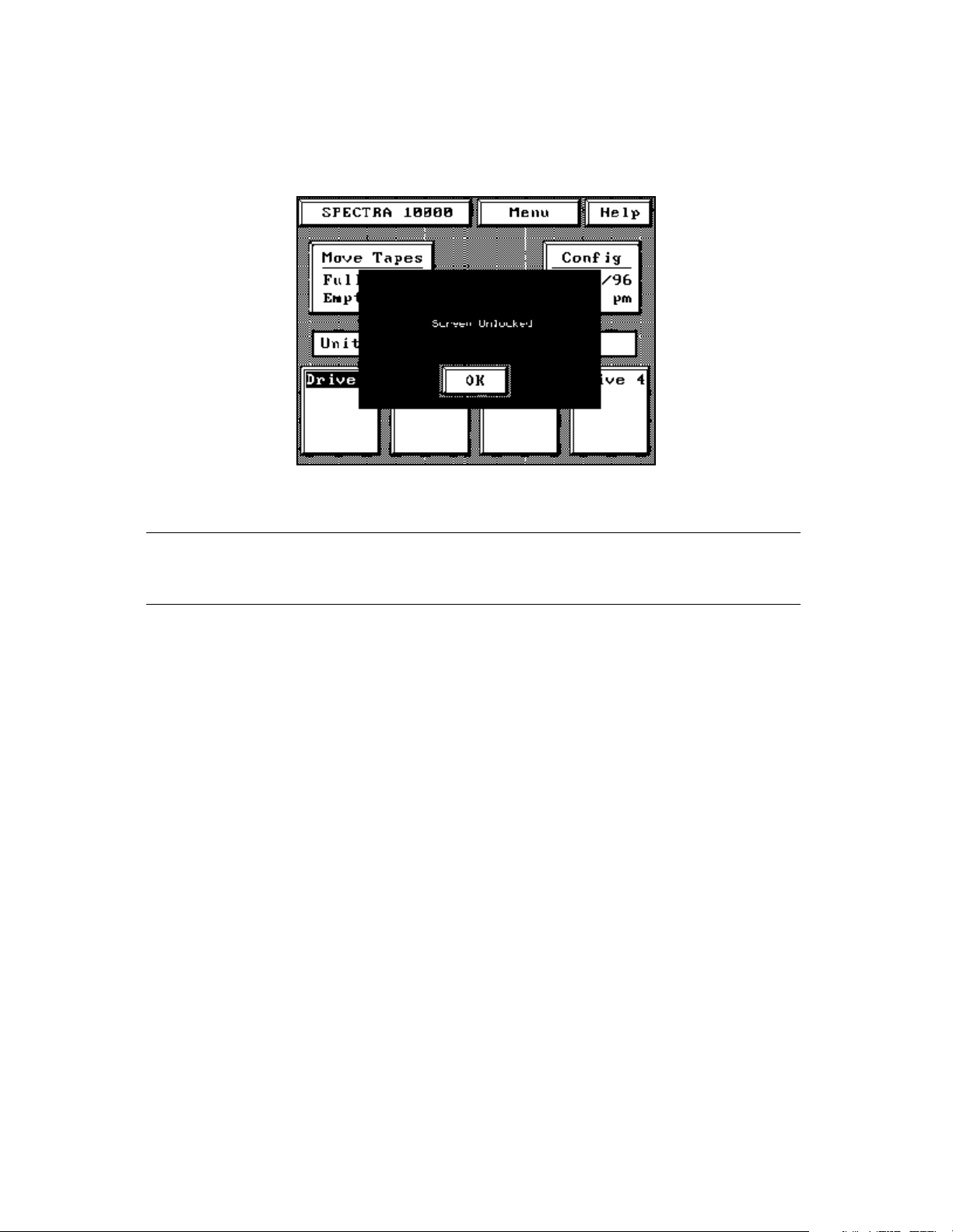
Chapter 5. Operating the Library
4. To access library functions, enter the user password when prompted. The
Screen Unlocked dialog box appears, prompting you for confirmation. Touch
OK. All library screens are unlocked (Figure 5-7).
Figure 5-7 The Screen Unlocked dialog box.
Note: The System Administrator password also unlocks the library
screens.
75
Page 76

Chapter 5. Operating the Library
Copying Data From Non-AIT Tapes to AIT Tapes
The media compatibility engine (MCE) allows you to copy data from one non-AIT data
tape to an AIT tape. From the main menu screen, touch MCE to access the MCE utility.
Note: The scope of the MCE utility is limited; use it only if no other
automated solution is available. The MCE is a raw copy utility that
only transfers the data from one tape to another; no other data
formatting is done. Not all source formats have been tested for
compatibility with the MCE utility.
The destination drive is one of the Sony AIT drives in the library. The source drive may
be an external stand-alone unit or it can be a drive in some other library. Generally,
any sequential access device on the SCSI bus can be the source.
Note: If you have data on tapes created in an Exabyte 8505 tape drive,
you can install an Exabyte 8505 tape drive in the library. This
makes the process easier.
Contact Spectra Logic Technical Support for information about the
Exabyte drive installation procedure.
Before continuing with an MCE data transfer, note the following:
• You must manually start each data transfer.
• If an Exabyte 8505 drive is installed in the library, and you are using this drive as
the source drive, the source tape must originate in the library door.
• Transfers can only happen on a one-tape-to-one-tape basis. You cannot piggyback
multiple source tapes onto the AIT destination tape even if significant space is
available on the destination tape after a transfer is completed.
• The data transfer will continue until either the source or destination tape ends, or
until no more data is found on the source tape.
Caution: If more data is on the source tape than will fit on the Sony tape,
the extra data on the source tape will not be copied.
• Data transfer rate is estimated at 500 MB per hour.
• The block size on the source tape must be 64 KB or less.
• File marks are copied as is to the destination tape; the data is not reformatted
during the transfer.
76
Page 77

Chapter 5. Operating the Library
Using the MCE Utility
To access the MCE screen, touch the MCE button from the main menu screen. The MCE
Select screen appears (Figure 5-8).
Figure 5-8 The MCE Select screen.
To copy a non-AIT tape to an AIT tape:
1. Select the location of the source tape. Touch the + or - symbols on the Source ID
box to scroll through the list of drives, and select one as the source drive.
The information box to the right of the Source ID selection box shows the
source of the data. Your source can be any of the drives in the library or any
device on either of the SCSI busses attached to the library.
2. Select the location of the destination tape. Touch the + or - symbols on the
Destination box to select the destination drive.
The information box to the right of the Destination box shows the destination
for the data. The destination drive can be any library drive.
3. Touch Copy to begin copying from the source tape to the destination tape.
Selection Box Information Box Meaning
– Source ID + 4 Bus 1 The source tape is in a device with SCSI ID 4 on Bus 1.
– Destination + Drive 1 The destination tape is in Drive 1 in the library.
77
Page 78

Chapter 5. Operating the Library
78
Page 79

6 Maintaining the Library
This chapter describes tasks you may perform when maintaining the library, including:
• Accessing Library Information
• Accessing Drive Information
• Replacing the Air Filter
• Changing Hosts
• Cleaning Drives
•Handling Tapes
• Packing the Library for Shipment
• Additional Media and Accessories
• Custom Bar Code Label Sequences
79
Page 80

Chapter 6. Maintaining the Library
Accessing Library Information
To access detailed library information, check the statistics and information located on
the Spectra 10000 screen.
Spectra 10000 Screen
From the main screen, touch SPECTRA 10000 to access this screen. To return to the
screen, touch anywhere on the Spectra 10000 screen (Figure 6-1).
main
Figure 6-1 The Spectra 10000 screen.
The Spectra 10000 screen lists:
• The address and phone number for Spectra Logic Corporation
• The application firmware code version (shell)
• The number of tape slots in the library
• The SCSI IDs for each installed drive and library SCSI bus
• The setting for the library configuration switch
• The serial number of the library
• The date the library was manufactured
80
Page 81

Chapter 6. Maintaining the Library
Accessing Drive Information
There are several ways to access detailed library information, including checking the
statistics and information located on:
• The Drive Information screens
• The ECC screens.
Drive Information Screens
The Drive Information screens show configuration, operation, and error information
for each drive. Highlighted drive buttons on the main screen represent installed drives.
Touch the drive button for the drive that you want to know more about.
First Screen: The Drive Info Screen
After touching the drive button, the Drive Info screen appears (Figure 6-2).
Figure 6-2 The first Drive Info screen.
SCSI ID / Bus The SCSI ID and the SCSI bus where the drive is connected.
Manuf The drive manufacturer.
Model The drive model.
Rev The drive’s firmware version.
Loaded Whether the drive is loaded with a tape.
W/P Whether the tape is write-protected.
Read Error Rate / Write Error Rate The read/write error statistics for that drive.
81
Page 82

Chapter 6. Maintaining the Library
From the Drive Info screen, you can:
• Touch the Upgrade button to move a firmware upgrade tape from the library door
into the drive. When the drive finishes reading the tape, the tape moves back to the
library door. See Upgrading Drive Firmware on page 71 for more information.
• Touch the Clean Drive button to move a cleaning tape from the library door into the
drive. Once cleaning is done, the tape moves from the drive back to the library
door.
• Touch the Reset button to reset a malfunctioning or non-responding drive.
Caution: Do not press Reset when a backup is in progress.
Second Screen: The Information Screen
From the Drive Info screen, touch More to access the second Information screen
(Figure 6-3). Touch either Exit or Main to return to the main screen.
Figure 6-3 The second Drive Information screen.
The second Information screen lists more information about the selected drive and the
way it is configured, including:
ALDC Drive or Compression Drive Drive is capable of data compression; all AIT drives
support hardware compression.
ALDC Enabled or Compression Enabled Whether drive is currently operating in hardware
data compression mode.
Time on Drum, Number Loads, Number Threads, Mechanism Motion Statistical information
about the selected drive.
Time Since Clean Calculation of time elapsed since the drive was last cleaned; this may
also be tracked through backup software and the two values may not match.
82
Page 83

Chapter 6. Maintaining the Library
MD S/N Drive information.
Revision Number Used only for diagnostic troubleshooting.
Drive S/N Drive serial number.
SCSI Bus Mode The mode sets the maximum data transfer rate.
Drive Switches Physical DIP switch configuration on the drive; the Emulate 1/2 and
Emulate 3/4 settings override the drive switch value.
Switch Override The drive configuration switch setting; confirm that this value matches
the values in the Emulate 1/2 and Emulate 3/4 configuration fields.
ECC Screens
The ECC1 and ECC2 screens display real-time error code correction information
compiled by the library when tapes finish unloading from a drive. If you enable ECC
Fault Check, an error report is sent to the host if drive error rates exceed certain levels.
To view the ECC screens:
1. Touch ECC1 on the Barcode screen or ER on the main screen to see the ECC1
screen.
2. From the ECC1 screen, touch ECC2 to see the ECC2 screen.
ECC Fault Check
The ECC fault check is a real-time error rate monitor. If you suspect that you may have
a tape problem or a drive problem, enable ECC Fault Check to check the performance
of the tape or the drive. When you enable ECC Fault Check, the library issues a Media
Warning error when certain conditions are met:
• More than 1,024 RAW retries per 1,024 groups written
• More than 11 read retries or 11 C3 (third-level ECC) errors per 1,000 groups read
The data for this warning is calculated using an average value of 1024 groups
(approximately 820 MB) of read or write data.
If the library displays a media warning, the data on the tape should be copied onto a
new tape, and the old tape should be discarded.
ECC Fualt Check is off by default. To enable ECC Fault Check:
1. Touch the + symbol to enable the ECC fault check to return an error report to
the host, or touch the - symbol to disable error reporting.
2. Touch Save Parms > No; it is not necessary to restart the library for these changes
to take effect.
83
Page 84

Chapter 6. Maintaining the Library
Replacing the Air Filter
Spectra 10000 libraries have a front panel with a removable air filter. Inspect these
filters every three to four months and replace as necessary. If the filter is contaminated,
replace it. A clogged air filter may cause operational errors due to excessive
temperatures inside the library.
To order replacement filters, contact your sales representative.
Caution: Some environments may require more frequent filter inspection
and replacement. If library filters get clogged quickly, you
should consider moving the library to a more dust free location
or improve the environment where it is located.
If air filters have excessive clogging due to neglect, it is
recommended that the filter be replaced immediately. After
replacing the filter, all tape drive heads should be cleaned. The
inside of the library, including the tape cartridges, should also be
cleaned with a low-pressure vacuum.
To check and replace the filter:
1. Insert a plastic card into the front panel release on the left side of the faceplate’s
slotted grill (Figure 6-4).
Figure 6-4 The front panel release.
84
Page 85

Chapter 6. Maintaining the Library
2. Swing the grill open (Figure 6-5).
Figure 6-5 Release the grill and swing it open.
3. Inspect the filter, replacing if necessary.
4. Close the grill, making sure that it snaps shut.
Changing Hosts
If you change the host system to which the library is attached, you will have to repeat
many of the steps described in previous chapters, including:
• Selecting a SCSI bus for the library
• Selecting the mode of library operation
• Setting up SCSI and power connections
• Adjusting drive emulation and library configuration
For lists and diagrams of the different SCSI cables available from Spectra Logic, see
SCSI Cables and Terminators on page 119.
85
Page 86

Chapter 6. Maintaining the Library
Cleaning Drives
Built-In Cleaning Feature
The Sony AIT drive uses a built-in head cleaner designed to last for the life of the drive.
This built-in cleaner works well, but it should not be relied upon as the only
drive-cleaning mechanism, particularly in environments where more excessive drive
head contamination may occur.
Spectra Logic recommends that drives be cleaned after every 100 hours of use in
normal data center environments. If excessive read or write errors occur while the
drives are being cleaned with that frequency, Spectra Logic recommends cutting the
cleaning time to every 50 hours of drive use.
Caution: Drive cleaning should be performed using only approved Sony
SDX-TCL cleaning cartridges. For ordering information, see
Purchasing Additional Library Accessories on page 64.
The AIT tape drive is an extremely reliable media storage subsystem; performing a few
simple maintenance procedures will keep the drives reading and writing reliably for
many years.
• For best performance with AIT tape drives, perform a read/write confidence test
with your backup software regularly. For information about performing this
operation, see the documentation for your backup software.
• As previously explained, the drive cleans itself when necessary. If further cleaning
is necessary, as may be indicated by the read/write confidence test, use only Sony
SDX-TCL cleaning cartridges. For ordering information, contact your sales
representative.
For more information about cleaning your drives, see Tape Drive Head Cleaning on
page 87.
86
Page 87

Chapter 6. Maintaining the Library
Tape Drive Head Cleaning
Head cleaning with a Sony SDX-TCL cleaning cartridge should be performed every 100
hours of drive use or less. Greater frequency is required in the following situations:
• When the library is installed in areas having high amounts of airborne particulates.
• When the drive fails to write or read data correctly.
• When the drive fails to eject a data cartridge.
Note: Dirty drive heads are not the only cause for read or write failures.
Damaged media can also cause this type of failure.
Most installations require scheduled cleaning using SDX-TCL cleaning cartridges.
Scheduled cleaning is definitely required in installations having high amounts of
airborne particulates. Most software applications have features that allow scheduled
automatic head cleaning of tape libraries.
Manual Drive Head Cleaning Operation
To manually clean your AIT tape drives, follow these steps:
Note: Use only Sony SDX-TCL cleaning cartridges.
1. Insert a cleaning tape into the front door of the library.
2. Select the drive that you would like to clean.
3. Press the Clean Drive button at the bottom of the Drive Info screen.
The library loads the tape and cleans the drive. When the cleaning cycle is
finished, the library returns the cleaning tape to the door.
4. After cleaning the drive, remove the tape from the library and check off one of
the boxes on the cleaning tape’s label (each check box represents one cycle for
which the cleaning tape can be used).
Caution: Do not use the cleaning cartridge for more than the number of
specified cleaning cycles indicated on the cartridge label.
5. Repeat Steps 1 through 4 for each drive in the library as necessary.
87
Page 88

Chapter 6. Maintaining the Library
Handling Tapes
Proper handling of tape catridges is essential to ensuring data integrity.
• Tape cartridges must be kept in a clean, dust-free environment. Store tape
cartridges in a sealed container when they are not loaded in the library.
• The individual tape case works for individual cartridges, and Spectra Logic’s
15-slot data cartridge magazine (DCM) with the dust cover installed works well
for storing multiple cartridges. (The Spectra Logic PackRack™ magazine shelf is
very convenient for storing multiple DCMs.)
• Avoid abusive handling or dropping of tape cartridges. If a tape is inadvertently
dropped, inspect it for damage. The dust cover on the tape must be properly seated
or it could become stuck in the tape drive.
• Condition the tape catridge. Before use, the tape should be conditioned by
exposure to the operating environment for a time at least equal to the period
during which it has been out of the operating environment (up to a maximum of 24
hours).
Use the following operating conditions for optimal tape performance.
• Temperature: 41°F to 113°F (5°C to 45°C)
• Relative Humidity: 20 percent to 80 percent (non-condensing)
• Maximum Wet Bulb Temperature: 77°F (25°C)
Extreme changes in temperature and humidity should be avoided whenever possible.
88
Page 89

Chapter 6. Maintaining the Library
Packing the Library for Shipment
If you are shipping the library:
From One Location to Another Note the packing procedures outlined under Packaging,
below.
To Spectra Logic for Service First contact Spectra Logic Technical Support to obtain a
Return Materials Authorization (RMA) number and the correct shipping address (see
Chapter 8. Technical Support and Service). Then follow the instructions under
Packaging, below.
Caution: The library warranty is voided by shipping the library without
the proper original packaging (for full warranty details, see
Limited Warranty on page 106). The following steps describe
how to properly pack the library for shipment.
Packaging
To pack the library for shipping:
1. Unload all tapes from the library, including tapes in the tape drives as well as
any tapes in the carousel slots.
2. Power off the library.
3. Remove all attached power, SCSI, and serial connections, including SCSI
terminators or Fibre Channel connections.
4. Place the anti-static bag over the library.
5. Place the library on top of the bottom foam cushions in the box (see Figure 6-6
on page 90).
89
Page 90
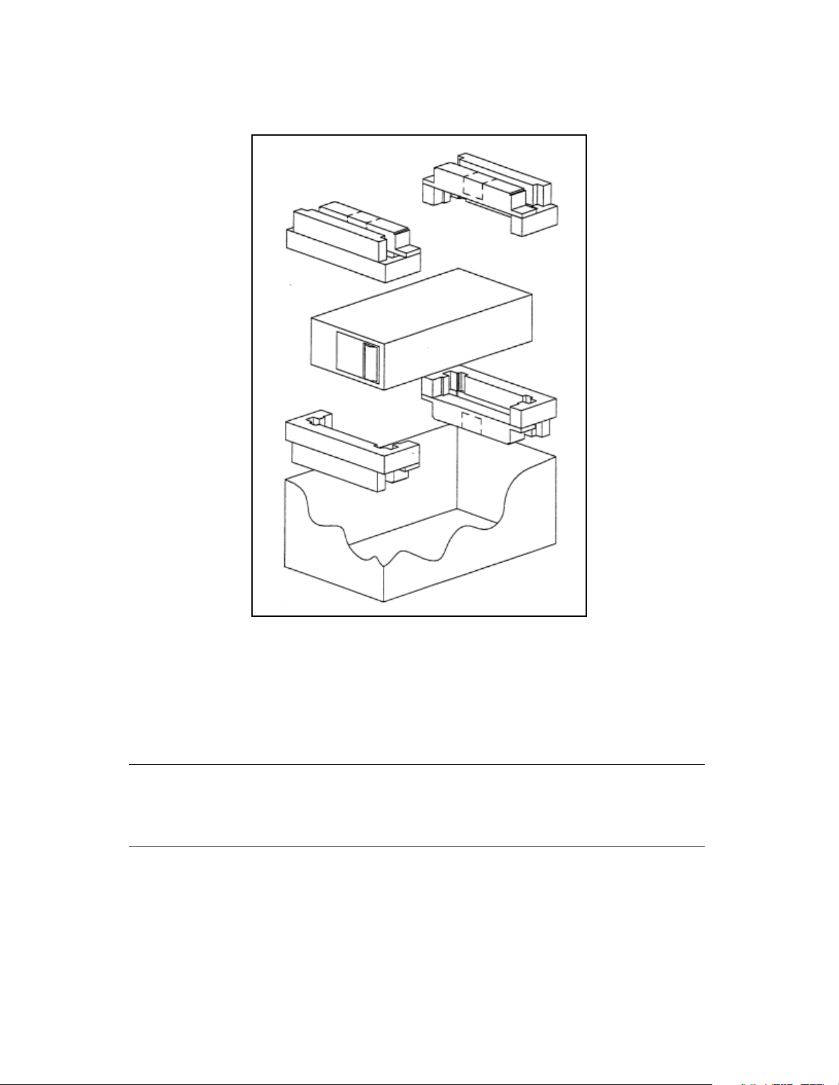
Chapter 6. Maintaining the Library
6. Place the top foam cushions over the library (Figure 6-6).
Figure 6-6 Correct packaging of the library.
7. Lay the necessary paperwork in the library box.
8. Seal the box with heavy packing tape.
9. Place the shipping label on the box.
Caution: Make sure that you use a shipping company approved by Spectra
Logic. (Contact Spectra Logic Technical Support for
recommendations.)
90
Page 91

Chapter 6. Maintaining the Library
Additional Media and Accessories
Certified Media
High-Quality Media Spectra Logic certifies only Sony AIT Advanced Metal Evaporated
(AME) cartridges, received directly from the manufacturer.
Lifetime Guarantee Spectra Logic provides a lifetime guarantee on all Certified Media.
Cartridge Packs Included with every 15-piece Certified Media order, cartridge packs
offer a simple, dust-free method of storing media outside the library. Each cartridge
pack stores up to 15 cartridges and has an integrated dust cover. (The 20-piece
Certified Media packs do not come with the cartridge packs to hold them.)
Bar Code Labels Every Certified Media order provides uniquely numbered, sequential
color bar code labels pre-applied to each cartridge, which ensures that you will never
have to deal with a duplicate bar code problem. These bar codes carry the same
lifetime guarantee that protects each Certified Media cartridge.
Bar Code Labels
Spectra Logic offers high-contrast and high-resolution bar code labels for the most
reliable operation. Bar code labels are sold in packages of:
• 10 (numbered by Spectra Logic)
• 180 (within the range of 000000 to 000179)
• 720 (within the range of 000000 to 000719)
Custom Bar Code Label Sequences Custom bar code labels are sold through distribution.
See the Spectra 10000 Library Release Notes for a list of suppliers.
For information on the required specifications, refer to Bar Code Specifications on
page 117.
PackRack Magazine Shelf
The PackRack magazine shelf makes the cartridge pack easier to use. A single
PackRack magazine shelf holds four cartridge packs (60 cartridges). The PackRack
magazine shelf’s simple design allows you to easily combine PackRack magazine
shelves as your storage needs grow.
91
Page 92

Chapter 6. Maintaining the Library
Ordering Media and Accessories
To take advantage of the many benefits offered by approved Spectra Logic media and
accessories, contact your sales representative, and reference the part numbers below.
To order Certified Media, you can also use the Certified Media order form found at
http://www.spectralogic.com/products/media/index.cfm/fuseaction/displayIndex/
Accessory Part Number
AIT-2 Media: Single Tape 5122
AIT-2 Media: 15-Tape Cartridge Pack * 90870670
AIT-2 Media: 20 Cartridges * 90870671
AIT-3 Media: Single Tape 5877
AIT-3 Media: 15-Tape Cartridge Pack * 90870721
AIT-3 Media: 20 Tape Cartridges * 90870673
AIT SDX-TCL Cleaning Cartridge 4569
10 AIT Bar Code Labels 92844103
180 AIT Bar Code Labels 92844100
720 AIT Bar Code Labels 90840260
AIT 15-Slot Cartridge Tray with Dust Cover 90870652
PackRack Magazine Shelf 90870676
* Certified Media
Contacting Spectra Logic Sales
United States Office
European Office
Phone: (800) 833-1132 or (303) 449-6400
Fax: (303) 939-8844
E-mail: sales@spectralogic.com
Phone: +44 (0) 870 112 2150
Fax: +44 (0) 870 112 2175
E-mail: eurosales@spectralogic.com
Ordering Media
media@spectralogic.com
92
Page 93

7 Troubleshooting
This chapter provides suggestions for solving problems that you might encounter when
configuring or operating the library.
Troubleshooting problems is divided into three sections:
• Library Operation Problems
• Tape Drive Problems
• Bar Code Problems
Note: If an error code is displayed on the library’s front panel, use
Spectra Logic’s interactive Sense Code Lookup to obtain the code’s
definition. This utility is located at http://www.spectralogic.com/
support/senselookup/index.cfm/fuseaction/DisplayIndex/.
Use this chapter to find solutions to the most common problems encountered with the
Spectra 10000 library. For additional suggestions, you can also search the Spectra Logic
Technical Support Knowledge Base at http://www.spectralogic.com/support/kbase/
index.cfm/.
Spectra Logic recommends trying these troubleshooting suggestions before opening a
support ticket with Spectra Logic Technical Support.
93
Page 94

Chapter 7. Troubleshooting
Library Operation Problems
Library hangs, will not boot, or does not communicate with host
1. Check that the library power cord is plugged into an active 120-volt or 220-volt
AC power source.
Newer power supplies switch voltages automatically, but older power supplies
have a switch that must be set to the current power source output or the power
supply may be damaged.
2. SCSI considerations:
• Ensure that all attached SCSI devices are using unique SCSI IDs.
• Ensure that all SCSI cables are attached and secure.
• Ensure that proper cables are used (proper termination of cables, proper
pinout of cables). Many non-Spectra Logic SCSI cables have impedance
qualities which do not meet SCSI standards.
• Ensure that the SCSI bus is terminated properly. Make sure that the host
controller card used automatic/manual termination, and that it is terminated
correctly. Terminators used on the library should be labeled Active for
single-ended libraries and Differential for differential libraries.
• Ensure that all devices attached to bus have the same SCSI configuration
(either single-ended or differential).
• Ensure that the SCSI cabling is of proper length for that number of attached
devices and SCSI configuration (single-ended or differential). Make sure you
take into account both internal and external SCSI cabling for all devices
(check the bus length limits in Selecting a SCSI Bus for the Library (SCSI
Libraries Only) on page 22).
3. Make sure that the library firmware is not corrupted.
lost or the library is reset while upgrading the firmware. To solve this, use the forced
firmware reload procedure as
70.
described in Forcing a Firmware Reload on page
This can happen if power is
Library boots, but will not come to Unit Ready state
1. Check all power and SCSI connections as described in the previous problem
description.
2. If you are using an Adaptec 2944 SCSI controller card, download the latest
Adaptec drivers from the Adaptec Web site.
Install them on your host system, then reboot the host and restart the library.
94
Page 95

Chapter 7. Troubleshooting
Library powers up with drive faults
If the library powers up, but registers faults on installed drives, touch one of the drive
buttons showing a fault to see a detailed display of error information.
If the error described is No response from SCSI target:
1. Check all SCSI cables and terminators on the library and host. All cables and
terminators must be of the correct type, termination, and pinout, and the
connections must be tight.
2. Check if the library SCSI IDs are properly configured. The library is shipped
with SCSI Bus 2 inactive, regardless of how many drives are installed. If three or
four drives are installed and the SCSI Bus 2 ID is not configured, Drives 3 and 4
will display faults when the library is powered up. If you are using SCSI Bus 2,
ensure that it has a unique SCSI ID.
Library powers up with screen blank
Check the library rear panel to see if one of the fuse lights is lit. If a fuse is blown, the
appropriate light illuminates for each of the three library fuses.
Replacing a Fuse:
1. Turn the library off and remove the power connection.
2. To remove the library cover, use a flat head screwdriver to remove the three
library cover screws on the rear of the library.
Figure 7-1 Remove the three cover screws.
95
Page 96

Chapter 7. Troubleshooting
3. Slide the cover back about one-half inch, then lift the cover off the library.
Figure 7-2 Slide the cover back. Figure 7-3 Lift the cover.
4. Check if you have a drive installed in the Drive 3 slot position.
• If you do not have a drive in the Drive 3 slot position, skip to Step 6.
•If you do have a drive in the Drive 3 slot position, proceed to Step 5.
5. If a drive is installed in the Drive 3 position, you need to remove it before you
can replace the fuses. To remove the drive:
i. Disconnect all the connectors from the rear of the drive.
ii. Unscrew the two captive screws fastening the drive sled to the base plate.
iii. Slide the drive sled toward the rear of the library, then lift the drive out.
96
Page 97

Chapter 7. Troubleshooting
6. The fuses are visible through the fuse cutout in the library base plate. Replace
the blown fuse with a fast-blow (standard) fuse.
5-volt fuse:
5V 8A-FB
D
r
i
v
e
3
S
l
o
t
12-volt fuse:
12V 2A-FB
D
r
i
v
e
4
S
l
o
t
Figure 7-4 The fuses visible through the cutout in the base plate.
7. If necessary, re-install Drive 3.
i. Slide the drive back into its slot on the base plate.
ii. Tighten the screws that secure the drive to the base plate.
iii. Carefully reconnect the SCSI and power cables.
8. Replace the library cover.
9. Reconnect all of the library cables.
10. Reboot the library.
12-volt
analog
fuse:
12V 8A-FB
Library screens are locked
Screens may have been locked using the User or System Administrator password. See
the administrator for the correct password.
Library screen does not respond to touch
You may have to power cycle the library to clear this error. Wait for the drive messages
Loaded and/or Active to clear before cycling power. Once the library and drives are no
longer active, power cycle the library and allow it to come ready. Retry the operation.
97
Page 98

Chapter 7. Troubleshooting
Drive fault displayed
Touch the drive button for the drive showing the fault (Drive 4 in Figure 7-5) to view
the detailed fault error information on the first Drive Info screen.
Figure 7-5 Drive fault displayed.
The Drive Info screen describes the cause of failure or displays an error code.
To find the best method for clearing the fault, find the error code in Spectra Logic’s
online Sense Code Lookup at http://www.spectralogic.com/support/senselookup/
index.cfm/fuseaction/DisplayIndex.
98
Page 99

Chapter 7. Troubleshooting
Drive alert displayed
Touch the drive button showing the alert (Drive 3 in Figure 7-6) to view the detailed
alert information on the first Drive Info screen.
Figure 7-6 Drive alert displayed.
The Drive Info screen describes the cause of the alert:
Tape Life The tape being used may be at the end of its usable life. If possible, replace
the tape and retry the store or restore operation.
Tape Drive Error Rates The alert may be caused by excessive drive error rates. Clean the
drive using a Sony SDX-TCL cleaning cartridge, as described in Cleaning Drives on
page 86. Then retry the store or restore operation
.
System fault displayed
Touch the System Fault button for information on the cause of the error. If an error
code is given, find the error code in Spectra Logic’s online Sense Code Lookup at
http://www.spectralogic.com/support/senselookup/index.cfm/fuseaction/
DisplayIndex. Use the suggestion given there to clear the fault.
After clearing the fault, power cycle the library, then verify that the unit comes to a
Unit Ready state. If the fault still does not clear, contact Spectra Logic Technical
Support for assistance.
99
Page 100

Chapter 7. Troubleshooting
System Fault with Drive Fault
A system fault may be concurrent with a drive fault. In Figure 7-7, the Drive 2 is also
showing a FAULT indication. For additional information on drive faults, see Drive fault
displayed on page 98. For additional library error code information, see the error codes
in Spectra Logic’s online Sense Code Lookup at http://www.spectralogic.com/support/
senselookup/index.cfm/fuseaction/DisplayIndex. .
Figure 7-7 System fault displayed.
Library does not respond to move commands
If the library does not respond to a move command and the initial source is a drive, the
tape may be stuck in the drive. See Tape stuck in drive on page 102.
Power is lost during firmware upgrade, and upgrade process will not restart
If power is lost during the upgrade, the process should restart when the library power
is restored. If power is cycled and the upgrade operation does not restart, perform the
steps described in Forcing a Firmware Reload on page 70.
100
 Loading...