


Series 800 Camera System User's Manual
2002
Spectral Instruments, Inc.
TUCSON, ARIZONA
P/N 2500

Spectral Instruments
Pt # 2500- 2

Spectral Instruments
TABLE OF CONTENTS
1 INTRODUCTION 7
1.1 S800 Series Camera System Overview 7
1.1.1 SICCD - The Important Distinction 8
1.1.2 CCDs And How They Work 8
1.1.3 Cooling The CCD - Why 10
1.1.4 Sensitivity Of The Camera 10
1.2 The S800 Camera 10
1.2.1 The Camera Head And Electronics 12
1.2.2 The Camera Power Supply 14
1.2.3 Camera Interface Module 14
1.2.4 Hooking Up Your Camera To Your Equipment 14
1.2.5 TDI Operation 15
1.2.6 Shutters And Timing Considerations 15
1.2.7 Lenses, Light Paths and Vignetting 16
1.3 The S800 Power Supply 16
1.3.1 Power Requirements 16
1.3.2 Power-On Startup Sequence 16
1.3.3 Externally Supplied Power 17
1.4 The S800 Camera Cable Set 17
1.4.1 Camera To Computer 17
1.4.2 Shutter Connector 17
1.4.3 The Auxiliary Port 18
1.5 The Cooling System 18
1.5.1 System Description 18
1.5.2 Hooking Up A Cooler 18
1.5.3 Cooling Cycle 19
2. RECEIVING YOUR S800 CAMERA SYSTEM 21
2.1 Shipping Configuration 21
2.1.1 Incoming Inspection Of Cartons 21
2.1.2 Opening The Cartons 21
2.2 Environment Requirements For S800 Cameras 21
2.2.1 Temperature - Humidity - Pressure 21
2.2.2 Electrical Requirements 21
2.2.3 Other Requirements 21
2.3 Assembly Of The Camera System 22
2.3.1 Assembly Of The Camera 22
2.3.2 Assembly Of The Camera Power Supply 22
2.3.3 Digital Camera Interface 23
2.3.4 Software Installation 24
2.3.5 Software Operation 24
2.4 Startup 24
2.4.1 Power-On Condition And Indicators 24
Pt # 2500- 3

Spectral Instruments
2.5 Commanding The Camera 25
2.6 Initial Tests 25
2.6.1 Types Of Images 26
2.6.2 Default Camera Readout Format 26
2.6.3 Dark Image 28
3. RUNNING THE COOLED CAMERA 31
3.1 Image Quality 31
3.2 Performance Metrics 31
3.2.1 Noise 31
3.2.2 Dark Signal Generation Rate 32
3.3 Other Metrics 32
4. USING THE CAMERA 33
4.1 Kinds Of Images 33
4.1.1 Bias Images 33
4.1.2 Dark Images 33
4.1.3 Light Images 34
4.2 Fixing Problems With Images - The Master Image Solution 35
4.2.1 Master Bias Images 35
4.2.2 Master Dark Images 35
4.2.3 Master Flat Images 36
4.3 Correcting Images 37
4.3.1 Why Correct At All? 37
4.3.2 How 38
4.3.3 Limitations On The Flat Field Process 38
4.3.4 Understanding The Scaling Effects 39
5. CAMERA SYSTEM WARRANTY AND SERVICE 41
5.1 The Warranty Conditions 41
5.2 Returning A Camera For Service 41
5.3 Diagnosing A Camera Problem 41
5.3.1 No Response 41
5.3.2 Fuses 41
5.4 Determining When To Refresh The Vacuum 42
5.4.1 Measuring The Camera Head Pressure 42
5.4.2 Why Pump 42
5.5 Refreshing The Camera Vacuum 42
5.5.1 Equipment Required 43
5.5.2 The Refresh Process 45
5.6 Cleaning The Window 46
Pt # 2500- 4

Spectral Instruments
5.6.1 Equipment Required 46
5.6.2 The Process 47
6. FIELD REPLACEABLE COMPONENTS 49
6.1 Cables 49
6.1.1 Camera Cables 49
6.1.2 Camera To PDCI Cable 49
6.2 The PDCI Card 49
6.3 The Camera 49
7. SYSTEM OPERATION AND SAFETY 51
7.1 Electrical Requirements 51
7.1.1 Incoming Power 51
7.1.2 Power Cords 51
7.1.3 Power Required 51
7.2 Physical Operating Conditions 51
7.2.1 Temperature 51
7.2.2 Humidity 51
7.2.3 Altitude 51
7.2.4 Vibration 51
7.2.5 Aggressive Vapors 52
7.3 Warnings 52
7.3.1 Electrical System 52
7.3.2 Camera Head 52
7.3.3 Opening The System 52
7.3.4 Refreshing The Vacuum 52
7.3.5 The Camera Window 52
8. TROUBLESHOOTING 53
8.0 Power Problems 53
8.0.1 Main Power Failure 53
8.0.2 DC Voltage Failure 53
8.1 Image Quality Issues 53
8.1.1 No Image 53
8.1.2 Streaks In The Image 54
8.1.3 Noisy Image 55
8.2 The Camera Seems Not To Be Stable 56
8.3 Camera Reports The Proper Temperature But Dark Is High 56
8.4 Camera Does Not Cool 57
8.5 Condensation On The Camera Window 57
Pt # 2500- 5

Spectral Instruments
APPENDIX A 58
CCD Readout Format 58
APPENDIX B 61
Multi-Port CCD Readout Parameters 61
Multi-Port CCD Image Pixel Data Format 61
Single-Port CCD Image Orientation 61
Over-Scan in Multi-Port CCD Readout 62
APPENDIX C 65
Sensitivity And Attenuation 65
Dual Slope Integrator Sensitivity 65
APPENDIX D 67
APPENDIX E 68
External Trigger 68
APPENDIX F 70
S800 DC Power Specification 70
Pt # 2500- 6
1 Introduction
This manual documents the standard Series 800 (S800) camera. Features that pertain
to a specific version of a camera are described in detail in Appendix G. It is
recommended that you read that section before operating your camera.
The S800 is a multi-port (from one to four ports) 14- or 16-bit camera where the
CCD can be cooled to temperatures in the range of –40oC using a thermoelectric
cooler. This camera system can read out at up to 1,000,000 pixels per second from
each port for multi-port CCDs. It reads out at up to 4,000,000 pixels per second as a
single port camera. It offers high precision, high stability and relatively short
readout times.
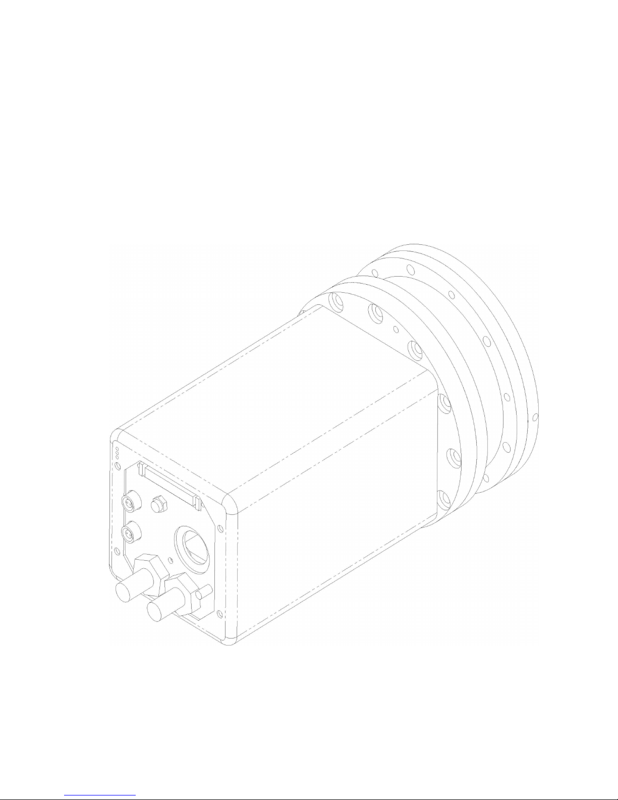
1.1 S800 Series Camera System Overview
A typical form of the S800 camera is shown in Figure 1. It consists of an evacuated
and sealed camera head chamber with the CCD inside and an attached module that
contains all of the electronics required to operate the camera. An external camera
Figure 1.

Spectral Instruments
power supply and a re-circulating water-cooler are also provided. The preamplifier
and analog processing circuits as well as the clock drivers, temperature and pressure
measurement hardware and digital image output driver circuits are all located inside
the electronics module.
The camera system is “self-aware” – that is, the camera knows, and reports to the
application software, all the information required to properly operate the camera
regardless of the type of CCD or the number of ports.
1.1.1 SICCD - The Important Distinction
Spectral Instruments manufactures precision digital imaging systems utilizing
scientific-grade CCDs. Innovative and detailed mechanical and electronic design
coupled with careful component specification and system manufacture provides
the ultimate in stable, high dynamic range digital imaging. Spectral Instruments
has invented the term Scientific Imaging CCD with SICCD as the symbol that
captures this high precision and high quality character of your camera. This
symbol occurs throughout our documentation as a shorthand reminder of those
high precision and high quality aspects of your camera system.
1.1.2 CCDs And How They Work
CCDs are used in a variety of consumer electronic products. A large assortment
of CCD sizes and types are available because of the popularity of this type of
sensor for low-cost digital imaging cameras. Most of these CCDs are not
scientific grade. Moreover, they are operated so as to give you a “TV” image.
CCD cameras that produce high quality digital images are designed to produce a
precision digital image and not a TV image. They are cooled well below ambient
temperature to reduce dark signal and they are operated in “slow readout mode”
to minimize readout noise.
Digital images are organized in a row/column format. Image elements (pixels)
emerge from a corner of the sensor. A sensor with more than one active corner
produces more than one stream of pixels during readout. Figure 2., below,
illustrates a single-port and a four-port CCD.
Referencing the left-hand portion of Figure 2., the checkered center region is the
imaging area. It is called the parallel register. To read out the CCD, the grid of
pixels is moved, one row at a time to the left, along columns, into the serial
register, labeled SR. Once a row is moved into the serial register, it is then
moved, one pixel at a time to the output node, shown as a triangle and labeled A.
A column is a line of pixels consisting of one pixel from each row. The CCD
does not read out columns, it reads out rows. But many characteristics of the
image that results are shared by all of the pixels at the same location in each row
(the same column) so they are analyzed as columns of information. Defects
involving multiple pixels are almost always column defects.
Pt # 2500- 8

Spectral Instruments
The address of the first pixel out of a CCD camera is row 0 column 0. Readout
occurs along rows, so the second pixel address is row 0 column 1. For a sensor
with 512 imaging pixels in a row and 512 rows, pixel 513 has the address row 1,
column 0. The last pixel out is row 511, column 511
.
One Port CCD Four Port CCD
Figure 2.
It is possible to move more than one row into the serial register before the serial
register is moved into the output node. It is also possible to move more than one
pixel at a time from the serial register into the output node before it is digitized.
This process is called binning. The total number of pixels is reduced in each
direction by the amount of binning in that direction. The effective size, on the
parallel register, of each binned “super” pixel is enlarged. This decreases the
resolution of the image by the binning factors (which may be different for rows
and columns).
Referencing now the right-hand side of Figure 2., the CCD illustrated supports
four-port readout so there are two serial registers labeled SR1 and SR2. Each
serial register is divided into two halves, which is shown figuratively as a black
line in the parallel register. The parallel register is also divided and that is shown
as a vertical black line. Neither black line exist in the CCD nor in the image that
is read out four ports, the divisions are presented as black lines for clarity in
showing how the single sensor is effectively divided into quadrants for four-port
readout. The first pixel comes out A, B, C and D at the same time. They are
combined into a single data stream with pixel data from A then pixel data from B
then C and finally D. This pixel data stream has pixels from all of the quadrants
interleaved. Software must sort them out so they are presented properly.
Spectral Instruments’ SI-Image software performs this task automatically. The
columns are still horizontal and rows are vertical in the final image just as if they
came out of a single port. SI-Image software displays the first pixel, the 0,0
pixel, at the lower left-hand side of your display. The pixels in each row are
displayed vertically. Row numbers increment from left to right in the display.
Pt # 2500- 9

Spectral Instruments
1.1.3 Cooling The CCD - Why
SICCD cameras are cooled to reduce the image contaminant called dark signal.
Images accrue this unwanted signal at a rate that decreases as the temperature of
the CCD is lowered. It is not the dark signal that is the problem (it could be
subtracted from the image), it is the noise associated with the dark signal. That
noise cannot be subtracted; it must be prevented.
The S800 camera system employs a thermoelectric cooler that is capable of
lowering the temperature of a typical CCD to -40
of the TEC is removed by a liquid heat exchanger that is connected to the camera
head. As long as the temperature of the camera is not reduced below the local
dew point, it is possible to lower the operating temperature of the CCD by using
chilled water in the heat exchanger rather than water at room-air temperature.
1.1.4 Sensitivity Of The Camera
SICCD cameras are designed to “see in the dark”. They do so quite well. You
can’t permanently hurt your camera by exposing it to too much light although, if
you have done so, it will affect your ability to make precise measurements of low
light level scenes until after you have warmed up the camera and then cooled it
back down again.
Dark images are a good way to find out how much light is leaking into your
equipment. An image obtained with no external light coming through the normal
path provides a view of how much light is coming from extra-normal paths. This
camera can see light leaks very well! To realize the full potential of your SICCD
camera, it, and the equipment to which it is attached, must be light tight.
o
C. The heat from the hot side
1.2 The S800 Camera
The camera is shown in profile in Figure 3. In this view, the position of the CCD
relative to the front flange, or plate, of the camera is shown. Also shown are the
overall dimensions of the camera. The camera back-view is shown in Figure 4.
Several different connections are required to integrate the camera into your
application. The dimensions are all millimeters.
Power is provided through a 14-pin twist-lock connector. The DC voltages to
operate the camera are supplied at this connector. The source of power may be a
Spectral Instruments S800 rack mount power supply or a DC source in your
application (typically through a DC - to - DC converter package supplied by
Spectral). In either case, a power sub-system is an integral part of a S800
camera. Connection to the computer is either through a 50-pin sub-miniature D
(looks like a SCSI) connector (as shown in Figure 4.) or by a MT-RJ type of fiber
optic data and communication connector.
The computer interface module will have a matching connector. Adapters are
available that split the twin MT-RJ fiber pair into two ST type of fibers. The
dual ST to MT-RJ combining equivalent is also available for use at the data
interface card. The data rate is limited to a maximum of 4,000,000 pixels per
Pt # 2500- 10

Spectral Instruments
second. If a multi-output CCD is used, the rate per output port is appropriately
lower.
Figure 3
Pt # 2500- 11
Figure 4

Spectral Instruments
Coolant is supplied to a pair of ¼" Swagelock VCO couplings. The appropriate
part numbers for the mating connector is: SS-4-VCO-3-4TA “Tube Gland
Adapter” and SS-4-VCO-4 “Female Nut”. Other gland forms are available if
flexible tube is not your choice for the cooling hose connection. Coolant can be
supplied by your application or by a refrigeration unit provided by Spectral
Instruments. It is necessary to maintain the back plate of the camera just above
the dew point to avoid condensation. It is important to monitor the supply line
temperature where chilled liquid is supplied to the camera so that no moisture
forms inside the camera electronics chamber.
The camera operates a shutter. Two types of signals for driving a shutter are
provided. The two-pin Lemo connector labeled shutter is designed to drive a 6-v
shutter from Vincent Associates or from Melles Griot. A suitable shutter can be
supplied by Spectral as an option. The 4-pin Lemo connector, labeled AUX,
provides a TTL or Opto isolated signal that indicates the shutter status across
pins 1 and 2. When the shutter is open the voltage across these pins is +5v.
When the shutter is closed the signal is 0 volts. The mating Lemo connector
specification is given in Section 1.4.2.
The camera can activate an exposure cycle in conjunction with an external event
through the trigger input signal across pins 3 and 4 of the 4-pin Lemo connector
labeled AUX. The signal can either be a TTL switch closure or an Opto isolated
version of the same switch closure. Details are shown in Appendix E.
Three small LEDs indicate: that the camera is receiving DC power, “PWR”;
whether the camera head internal vacuum needs to be refreshed, “VAC”; and
whether the camera temperature regulation is active, “COOL”, by, respectively,
green yellow and green lights. The light comes on when the condition is true.
1.2.1 The Camera Head And Electronics
The camera consists of a camera head chamber and an electronics module that is
physically attached to the camera head. All of the electronics required to operate
the camera are located in the electronics module.
As mentioned in Section 1.1.3, the CCD is cooled to reduce dark signal. Just as
your eyeglasses fog when you come out of the cold into a warm room, cold
objects condense moisture from the surrounding air. The CCD is maintained
inside a sealed evacuated camera head chamber to insure that moisture does not
condense on the cold CCD.
In a lens-based camera, the camera head chamber aperture seal is a fused-silica
window large enough that the CCD sensor is not shaded from the incoming
beam. The CCD sensor is typically located 14.85 mm behind the front surface of
the window. The window thickness is typically 3 mm. Other back-distances and
window thickness options are available for custom applications.
Pt # 2500- 12

Spectral Instruments
Fiber-optic based cameras seal the camera head chamber at the fiber optic. The
fiber optic protrudes a few millimeters in front of the chamber so the camera can
be coupled to other optics.
The S800 camera is cooled by a thermoelectric cooler. That cooler is capable of
o
cooling the CCD below –40
C for small size CCDs that are not connected to a
fiber optic. The cold end of the TEC is inside the camera head vacuum chamber.
The amount of current flowing to the CCD is regulated to maintain the CCD at
the operating temperature, which is typically between –20
o
C and –40oC.
As shown in Figure 5., a 6X M5 115 mm clearance bolt circle pattern is provided
for mounting the camera to your application. As shown in Figure 4., a 4X M5
tapped bolt circle is also available on the back plate if mounting the camera by
the back plate is appropriate.
Pt # 2500- 13
Figure 5.
Front Plate

Spectral Instruments
1.2.2 The Camera Power Supply
The DC voltages necessary to operate the camera are provided through a separate
power supply module. This module is connected to the camera head by a 14-pin
Twist-lock connector. The power supply pin-out is shown in Appendix F.
WARNING: Turn off the power to the camera power supply before connecting
or disconnecting the camera power connector either at the camera head or at the
power supply!
The SICCD camera is buffered against electrical transient events - radiated or
conducted - through the power connection. This buffering suffices for
coexistence of the camera with typical laboratory equipment.
WARNING: The camera system incoming power mains must be filtered against
exceedingly strong transients such as that produced by lightning.
1.2.3 Camera Interface Module
The camera communicates to the host computer either through a proprietary
AIA-style communications and data transfer protocol or by a MT-RJ fiber optic
link. The two different communication protocols utilize different host interface
cards. Both types of connection permit the camera to receive instructions from
application software and to read the status of the camera through a serial
protocol. The data transfer is different between the two options.
The copper-wire AIA connection transfers image data down the AIA cable as 16bit parallel pixel values over differentially driven lines. The communication
signal is RS422 bi-directional with control characters and parameters transmitted
to the camera and status and configuration parameters transmitted back to the
host computer.
The optional fiber optic communication and data protocol replaces the AIA
drivers and receivers on both ends of the communication with a two-fiber bundle.
The communication is still serial but the pixel data is also transferred serially and
reconstructed at the fiber optic interface module.
1.2.4 Hooking Up Your Camera To Your Equipment
A detailed description of the system setup and interconnect process is provided
in Section 2.3. An important system aspect of connecting the camera to your
application is minimizing ground loops. Ground loops result from small voltage
differences among grounds of different power sources. They can have a serious
effect on images obtained from your SICCD camera. If ground loops are present,
various lines, bars, chevrons or wood-grain patterns can occur in the background
of low light images (they show up especially well in a bias image). The patterns
are of no significance when imaging high light level scenes but can disturb low
light images and are exceedingly annoying as the eye is very good at picking out
such patterns even if the amplitude is not statistically measurable.
Pt # 2500- 14

Spectral Instruments
Spectral Instruments has designed a camera that is essentially bias-pattern-free
when it is operated from a suitable power source as directed in Section 2.3. If
that camera is mechanically connected to some apparatus that is at a different
ground potential than the power source, small currents flow through the camera
body. These small currents are always visible in the image; they are always
undesirable!
If the camera and the equipment cannot be grounded to the same point, it may be
necessary to introduce an electrical insulator (including screws) where the
camera physically is attached to your equipment.
1.2.5 TDI Operation
Spectral Instruments cameras can image in conjunction with a moving field. In
this mode the camera operates either through a timed delay or by synchronizing
the shifting of the image on the sensor to an external event. In the latter case, the
trigger input provides the synchronization. In TDI mode, a frame is discarded at
each end, which is overhead for this imaging mode.
1.2.6 Shutters And Timing Considerations
The camera provides millisecond resolution in timing your SICCD camera. That
resolution is useful when the camera is shuttered by equipment that responds in
tens of milliseconds.
The camera is also designed to obtain “images upon external signal”. This is
known as “triggered mode”. In this mode the camera is programmed to clear
charge continuously with the CCD staring into the application waiting for a
trigger event. The trigger event is provided by the application. The camera
ceases clearing immediately (within 5 milliseconds depending upon the CCD)
upon receipt of the trigger and stares into the application accumulating an image.
The camera stares for the currently set integration time and then it reads out.
When a SICCD camera is shuttered by any conventional multi- or twin-blade
shutter mechanism, the shutter requires some time to open and to close. These
shutter open and close delays must be considered when obtaining short
exposures. A user changeable shutter-close delay is programmed into the
exposure readout so readout does not start until the shutter is fully closed.
However, a good twin-blade shutter requires at least ten milliseconds to open as
well as close. A 10-millisecond exposure with such a shutter means that the
integration time is effectively 20 milliseconds for the center of the image and is
much less for the edge of the image. The resulting variation in effective
exposure is noticeable. The exact pattern observed depends upon the type of
shutter. In every instance, you must not expect uniformly exposed images when
the exposure times are within a factor of 10 of the shutter delay times. Large
shutters can take more than 50 milliseconds to open and close.
Pt # 2500- 15

Spectral Instruments
While it is possible, in principle, to correct for shutter-caused patterns in a flat
field image, shutters are electro-mechanical devices that are not very stable so
one flat field may not suffice for effective shutter shading correction.
1.2.7 Lenses, Light Paths and Vignetting
Spectral Instruments usually does not provide a lens. This is because most
applications that can utilize the precision of a SICCD camera already provide an
image plane at which the SICCD camera is positioned. Typically, a lens is only
useful for imaging with the camera “straight out of the box” and is usually
discarded soon thereafter.
There is always some variation across the image of a “uniformly illuminated”
application. It is exceedingly difficult to obtain a uniform illumination field and
most equipment vignettes to some extent. There are methods to compensate for
this vignetting and they are discussed in Section 4.
One type of application that is frequently troubled by imaging artifacts is the
“long focal ratio”. When the camera is exposed to light that is nearly collimated,
that beam acts to reveal very small dust specks on the window. The camera is
assembled with great care to eliminate any dust on the inside of the window. The
outside of the window is also cleaned and the camera is shipped with a protective
cover to keep the window clean. Life conspires to change that. Dust particles
collect on the outside of the window. Only those customers with applications
involving highly collimated incoming beams will notice. What they will notice
are “little donuts”. These are shadows of the dust particles on the outside of the
window. They can be corrected using a process discussed in Section 4., but if
your application does not include image correction you will see the dust in a
collimated beam illumination of the camera.
Although cleaning the outside of the window is not recommended; Section 5.6
describes how to clean the window of your camera if such activity is really
necessary.
1.3 The S800 Power Supply
The round 14-pin power connector (POWER) connects to a cable leading to the
camera head. This connection provides critical voltages to operate the CCD and
must supply completely noise-free DC voltages to the camera.
1.3.1 Power Requirements
The power supply operates on incoming AC power in the 48 to 62 Hz frequency
range and can run on 100, 120, 230 or 240 volts. A power entry module allows
the power selection to be changed. The fuses required for the incoming mains
are located in the power entry module.
1.3.2 Power-On Startup Sequence
When power is applied to the camera head the DSP turns on, reads stored
parameters from a local flash RAM and is ready to operate the CCD. The DSP
Pt # 2500- 16

Spectral Instruments
flashes the power LED three times to indicate that it is ready. Static voltages are
applied to the CCD. Continuous clearing of the CCD is started. The camera is
not caused to expose and readout without an application command to do so.
1.3.3 Externally Supplied Power
The camera may be operated from an application-supplied DC power source. In
principle, it is possible for the application to provide all of the DC voltages
required by the camera. These voltages are detailed in Appendix F.
More likely, your application has a 28-volt or 24-volt DC power source that is
preferred for operating the camera instead of sourcing 110- or 230-volt AC
power to a Spectral Instruments power supply. Spectral Instruments provides
DC - DC converter modules (two modules, one for the camera and the other for
the TE cooler) that have two-pin input connectors to receive the incoming DC
power. Each module produces all of the camera-specific DC voltages which
“wye” into a standard 14-pin output power cable. The length of the cable to the
camera head should be short when the DC - DC converter is used in order to
minimize line drop. Such converter modules should be located somewhere near
the camera head and mounted according to the requirements of the application.
1.4 The S800 Camera Cable Set
1.4.1 Camera To Computer
The camera communicates with the computer either by a copper-wire 50-pin
parallel digital connection or by a two-fiber fiber-optic serial connection. In
either case, a communication link is included within the cable along with the data
lines. The copper-wire cable to the computer connects to the Spectral
Instruments proprietary PDCI AIA digital imaging module by a 50- to 68-pin
AIA cable.
The fiber optic connection connects to a Spectral Instruments proprietary PDCI
FO fiber optic input module. This module presents the identical interface
register set and I/O addresses as the PDCI AIA module. The host computer
drivers are identical for the two interface modules.
The fiber optic communication configuration provides “fiber active” indicators at
each end of the fiber that are turned on if the fiber is not properly connected.
Indicators are located at the camera head next to the link and at the computer
interface module.
1.4.2 Shutter Connector
If a shutter is supplied, that cable is also included with the camera system. At the
back of the camera head, a 2-pin shutter connector port, labeled SHUTTER, is
provided for cameras that use a standard 6-volt shutter. The camera head end
varies to meet the application requirements and/or physical shutter selected.
Pt # 2500- 17

Spectral Instruments
The camera shutter connects to a Lemo connector that is available as LemoUSA
part number FGG.0B.302.CLAD52Z. The wire must not be bigger than 22gauge and the cable must be between 4.1 and 5.0 mm in diameter.
1.4.3 The Auxiliary Port
A 4-pin Lemo connector at the camera head provides for external control out of
and in to the camera. The current status of the camera shutter is provided as a
signal between pins 1 and 2 of the auxiliary port. When the shutter is open the
signal is + 5 volts. Otherwise it is 0 volts. A switch closure between pins 3 and
4 on the auxiliary port sends a signal to initiate an exposure when the camera is
in the "triggered exposure" mode.
The auxiliary connects to a Lemo connector that is available as LemoUSA part
number FGG.0B.304.CLAD56Z. The wire must not be bigger than 22-gauge
and the cable must be between 5.1 and 5.5 mm in diameter.
1.5 The Cooling System
1.5.1 System Description
The thermoelectric cooler that lowers the temperature of the CCD is sized
according to the load provided by the camera head configuration. The design
load is determined by the size of the CCD, the presence of a fiber optic
attachment or the distance between the CCD and the window. The operating
load is very much affected by the pressure inside of the camera head chamber.
The watts to be removed from the camera head by an external cooling liquid
supply vary according to the size of the TEC. TE coolers run between 30 and
150 watts. Cooling liquid at +20oC flowing at rates between 3 and 10 liters per
minute are sufficient for TE coolers at 30 and 150 watts respectively.
It is possible to supply cooling liquid at a controlled temperature by use of a
closed cycle refrigeration system. This is necessary in the event that the ambient
temperature is high. It is important to avoid bringing the inlet tube to the camera
head below the dew point because condensation would result and condensation is
always bad.
1.5.2 Hooking Up A Cooler
The camera is fitted with two ¼” Swagelock VCO fittings. Spectral Instruments
supplies a closed cycle refrigeration system as a cooling option. The liquid is a
50% ethylene glycol and 50% de-ionized water mixture. It is important that the
fluid used be non-corrosive to the metal camera head chamber. As a minimum, a
buffered solution must be used. Glycol is not required unless the system is
exposed to temperatures that could freeze.
Pt # 2500- 18

Spectral Instruments
1.5.3 Cooling Cycle
The camera will start to cool immediately when the TE cooler is turned on. It
requires a few minutes (for a small CCD camera) to stabilize and it will only
stabilize if the temperature requested is at least five degrees warmer than the
open-loop temperature.
If the camera is started running with the stabilization temperature requested to be
colder than the TEC can provide, the temperature of the CCD will lower to an
initial minimum and then rise again to the "open loop" temperature. This small
rise in temperature reflects the attainment of a thermal equilibrium throughout
the mechanical parts of the camera head.
To disable cooling the camera, set the stabilization temperature above the current
ambient temperature. Alternatively, the cooling On/Off configuration parameter
can be used to enable or disable power to the TEC.
Pt # 2500- 19


2. Receiving Your S800 Camera System
The camera system is shipped in double-walled heavy weight cardboard boxes that are
industry standard for fragile electronic equipment. Do not discard these cartons if the
equipment is to be transported.
2.1 Shipping Configuration
The camera and the computer interface module, with its cable, are shipped in one box.
The DC power supply, with its cable, is shipped in a second carton. A cooler, if
provided by Spectral, is in another carton. The test report and the SI-Image software
are shipped in the box with the camera.
2.1.1 Incoming Inspection Of Cartons
Inspect the cartons to make certain that there is no visible damage. Check for
puncture-type damage. If there is any evidence of damage, have the packages
inspected by your local freight carrier so that responsibility for damage to the camera
components is borne by the carrier.
2.1.2 Opening The Cartons
Open the cartons in such a manner that they can be reused. It is important to use these
or equivalent packing materials if the camera system is to be transported.
2.2 Environment Requirements For S800 Cameras
2.2.1 Temperature - Humidity - Pressure
The camera system operates at temperatures from 60oF (15oC) to 95oF (35oC). The
camera system operates at relative humidity from 10% to 60%. The camera is rated to
operate from sea level to 10,000 feet.
2.2.2 Electrical Requirements
The camera system runs on regular AC power as long as the frequency is between 48
Hz and 62 Hz and the voltage is 100, 120, 230 or 240 volts. The requirements for the
fuses are described in Section 2.3.2. The system must be protected against line surges
by using a surge-suppresser in the incoming AC power line.
2.2.3 Other Requirements
The camera components must be protected from aggressive atmospheric conditions
such as are the result of operating in salt laden air or in air that contains corrosive
chemical vapors.

Spectral Instruments
2.3 Assembly Of The Camera System
Camera assembly consists of verifying proper AC line voltage setting, connecting AC
line power to the power supply, connecting the power cable between the power supply
and camera, and connecting the computer interface cable between the camera and the
computer interface card.
Figure 6.
S800 Interconnect Diagram
Figure 6. shows how the components connect and how the main power must be
connected.
2.3.1 Assembly Of The Camera
Assembly of the camera involves mounting the head onto a test fixture or onto your
equipment. Normal precautions should be taken against handling damage.
2.3.2 Assembly Of The Camera Power Supply
The AC power setting must be verified or set to the proper configuration before power
is applied to the camera. The power-entry module has a recessed IEC male connector
for the power cord. To the right of this recessed male plug is a fuse module that has an
indicator for the current power configuration. The indicator is a white dot that appears
to the right of one of the four power settings marked in the black plastic on the fuse
holder. The indicator MUST agree with the mains power that will be used. If the
indicator does not show that the camera power supply is set to the proper AC power, it
must be changed. All of the output fuses must also be changed whenever the incoming
power setting is changed from 100/120 to 230/240 volt configurations. The fuse
Pt # 2500- 22

Spectral Instruments
requirements are given below and are labeled on the back of the power supply. Power
and fuse changes are accomplished as follows:
1) Make certain that the power cord is not plugged into the power supply!
2) Using a small flat-head screw driver, insert it into the small recess on the left hand
side of the fuse holder module. Gently pry the fuse holder out of the module. Inside,
fuses are visible. Inspect the fuse values. For 230-240 mains, the fuses must be T1.0
fuses or T1.5 depending upon the TEC power supply installed. For 100-120 mains the
fuses must be T2.0 or T3.0 fuses, again depending upon the TEC supply installed. All
of the fuses are 5-20 (metric) fuses and they must be TUV approved.
3) Using a small pair of pliers or strong tweezers, carefully remove the very small
circuit board assembly that resides on the right hand side of the cavity exposed when
the fuse holder was removed. This is a 2-part power selector. The circuit board,
inserted with the correct power indicated at the leading edge of the circuit board,
actually makes the proper power connection to the power entry module. The small
plastic indicator can be “wiggled around” so as to point its dot in the opposite
direction. The effect of repositioning the dot is to move it up or down to indicate the
proper power selection when the unit is reassembled. Once the dot is opposite the
power label you selected, replace the circuit board assembly.
4) Insert the fuse holder module and inspect the power setting now indicated by the
white dot. If it is not correct then redo steps 2 and 3 until it is correct.
5) The six fuses (labeled F1, F2, F3, F4, F5 and F6) for the DC power must be correct
for the incoming line voltage. The first three fuses are identical and are T0.5A for
100/120 volts incoming power. The second set of fuses are also identical and are
T1.5A for 100/120 voltage. For 230/240 the two sets are 1.4A and 0.75A
respectively.
Once the AC power setting on the electronics unit has been set up for the local AC
power, assembly of the camera consists of connecting the power supply cable to the
camera.
2.3.3 Digital Camera Interface
Spectral provides two versions of the computer interface module. One is the PDCIAIA parallel data card that is a PCI bus interface card for the Spectral Instruments 500,
600 and 800 Series cameras. It accepts camera image data at rates up to 10 MHz and
directs it to computer memory by bus-master direct memory access. It also transmits
and receives RS422 levels for camera communications. The interface card connects to
the camera by a 68-pin to 50-pin high-density cable.
The other data interface option is the PDCI-FO, a fiber optic module with the same
characteristics insofar as the host computer device driver is concerned. It has a MT-RJ
fiber optic connector instead of the 68-pin AIA connector.
Pt # 2500- 23

Spectral Instruments
To install either module in your computer, first turn off your computer and plug the
interface card in any available PCI slot. Insert the Spectral Instruments CDROM into
the CDROM reader on the computer.
2.3.4 Software Installation
Camera control and imaging software is provided by Spectral Instruments. This
imaging software, called SI-Image, is supplied on a CDROM. The installation disk
contains a setup.exe installation program that automatically detects the operating system
(Win9x, WinNT, Win2K or WinXP) and installs the appropriate driver and camera
interface .dll into a directory path that you may redefine as part of the installation.
When the computer is switched back on, a Windows 98 operating system will find that
the card has been installed and finish the installation. For Windows NT and Windows
2000, become system administrator and run the setup.exe on the CDROM. Note that
installing the software as administrator requires a re-boot cycle to again be able to run
the software as a normal user.
2.3.5 Software Operation
The software is typically installed into a sub-directory under the directory containing
other Program Files. Two icons are provided, one to run the program and the other to
uninstall the application. The SI Image SGL program uses an internal representation of
image data as floating point pixel values which means that image data are 32-bits (4bytes per pixel). The data can be stored under any of several file-storage formats. It is
important to select a file storage format that is appropriate to the range of values in the
image data! If the image has negative values (as a result of image arithmetic perhaps)
those pixels are not represented correctly except as signed 16-bit integers or as 32-bit
floating-point values.
Once the program screen appears, the pull-down labeled Operate provides a control to
initialize the camera. When this has finished properly, the camera is then ready to
operate. A software manual, Part # 2523, is provided as a .pdf file on the CDROM that
also contains the software.
2.4 Startup
After the software is installed, the camera has been connected to the power supply and the
data cable connected to the PDCI interface, the system is ready to image.
2.4.1 Power-On Condition And Indicators
When the unit is switched on, the ”PWR“ indicator on the camera head flashes three
times and then remains illuminated. The amber high-pressure ”VAC“ light will turn on
if the camera pressure is above 4 torr. This indicates that vacuum service is required.
The green “COOL” LED indicator light on the back of the camera housing turns on
when DC power is applied to the thermoelectric cooler. The brightness of the light
shows the amount of power being applied to the cooler. When the TE cooler is first
turned on, maximum cooling power is applied and the light is bright. When the
Pt # 2500- 24

Spectral Instruments
camera has reached the selected operating temperature the “COOL” LED glows but not
as brightly.
2.5 Commanding The Camera
The camera accepts a number of commands and parameters from the host computer. The
commands are all single ASCII letters, which can be upper case or lower case. No
termination characters, such as carriage return and or line feed, are necessary to initiate
the command. Only those characters that are part of the command set are valid. The
command set is available from Spectral Instruments upon request as part number 1870.
Termination characters are treated as invalid commands and thus should never be
transmitted. For any valid command, the command is echoed back to the host, the
command is executed and then a reply of an ASCII Y is sent, to indicate successful
completion of the command, or a reply of an ASCII N is sent to indicate that the
command is invalid. Some variations occur in exactly when the various Y responses are
transmitted to the host computer depending upon the activity commanded.
If a command requires a parameter or parameters, it (they) must be sent as 32-bit binary
word(s) with the most significant byte sent first, immediately after the command letter
echo is received. The camera knows from the command what sort of parameter(s) is/are
expected and waits for transmission of requisite number of bytes. The parameter(s) is/are
not echoed. The camera waits for the number of bytes that are expected for the command
so it is important that every command that requires a parameter be followed by the proper
number of bytes. After the parameter(s) is/are received the terminal Y or N response is
returned. If a parameter is out of range for that command a N reply is issued and the
command is not executed.
Commands from the host computer, that ask the camera for status or configuration, send
the information after the command is echoed. These numbers are also 32-bit and are sent
with the most significant byte first. After the parameters are sent the Y or N is sent. The
camera communications protocol is documented also under SI Part Number 1870.
2.6 Initial Tests
To assure the camera is functional even before it is cooled, it is reasonable to run through
initial imaging tests while the camera is cooling down. Final performance metrics cannot
be undertaken until the camera has stabilized at its regulating operating temperature.
There are several configurations the camera can assume. For some of them it is not
possible to “take an image” without fully integrating the camera into the application
apparatus. This manual uses tests for which a dark environment is sufficient.
The following also assumes that the SI-Image program is used to run the camera. Any
other operational software will work as long as the equivalent camera operations can be
commanded from within that software.
Pt # 2500- 25

Spectral Instruments
2.6.1 Types Of Images
SICCD cameras provide access to all of the components of an image. These are:
1) the electrical offset introduced to keep all of the pixel values as positive integers the bias,
2) the dark image which includes the bias and shows the sensitivity of the camera to
thermal signal and
3) the light image at which the camera was directed. The light image includes the
dark and the bias components.
If the exposures are short and of constant duration, then the bias and dark images need
not be measured separately - particularly if a dark image is obtained essentially for
every light image. Bias images may exhibit a low-level spatial structure that is stable
over time. The bias image is different according to the way the camera is set up to
image. It changes with readout speed, attenuation and binning. The bias image is a
uniform array of very low-level “gray values” superimposed upon on a background
DC offset. The value of the offset can be set by software command.
Binning, attenuation (gain) and readout speed all affect the bias image. Some
structure may be visible along one edge of the bias image. This stable structure
reflects the analog readout electronics responding to the startup transients involved in
beginning each row read out. Bias images also incur some thermal signal (dark
image) if the readout is slow and the camera is warm. This thermal signal introduces
a ramp effect from one side of the bias image to the other. Referring to Figure 7., the
thermal signal is uniform along rows and increases along columns. The plot
overlaying the image in Figure 7 shows a horizontal cross section at the red cursor in
the image. Colors only show up in the .pdf form of this document.
Dark images are bias images along with the additional thermal signal accrued during
the exposure time. Dark accrues more or less uniformly over the entire sensor
although some areas of the CCD may contribute thermal image at a higher rate than
other areas. This non-uniformity is stable for a given exposure.
Very bright “speckles” will appear in dark images – in fact, they sometimes appear in
bias images as well. These are the record in the CCD sensor made by the passage of
highly energetic particles. Classical CCD imaging literature calls these particles
“cosmic rays”, in this manual they are referred to as spurious events. They are
random in occurrence and must be located as described in Section 4.
2.6.2 Default Camera Readout Format
The default image readout format, as delivered by Spectral Instruments, reads out more
pixels than just the illuminated pixels. This readout mode is called “overscan”, reading
imaginary pixels as well as illuminated pixels. Appendix A contains an illustration of
overscan readout mode.
When overscan readout is employed, the images that result depend upon the design of
the CCD sensor itself. Table A1., in Appendix A, includes the pixel count appropriate
Pt # 2500- 26

Spectral Instruments
to overscan some representative CCDs. The illustration shows you how to relate each
of the tabulated parameters to the image read from the camera.
Figure 7, below, shows an image from a warm camera displayed with SI Image and the
plot for a column near the center of the image overlaying the image.
Camera Image Showing Overscan
The serial register is on the left hand side of the image. The first pixel read is displayed
at the lower left hand corner and the readout progresses up rows starting with the first
row at the left and progressing to the last row that is displayed on the right hand side of
the image. The image is darker on the left and brighter on the right. The column plot
shows the “ramp” of increasing dark signal with time. Because of the slow-scan
Pt # 2500- 27
Figure 7.

Spectral Instruments
readout, rows on the right hand side of the image were exposed to dark signal longer
than those on the left hand side – hence the ramp.
The image shows dark bands at the bottom and top. These bands are from pixels that
were digitized but that did not come from the active area of the sensor. The band at the
bottom is the 8-pixel prescan extension of the serial register. The wider band at the top
is the post scan extension of the serial register. The pre scan and post scan are
combined into the general term overscan.
The image shown in Figure 7 includes overscan in the parallel direction as well as in
the serial direction. It is not too easy to tell but the last 100 rows in the image have all
about the same signal level since all of those rows experienced the same exposure to
dark signal during readout. This is because they do not exist on the sensor and are sort
of “created” at the far (from the readout) edge and transit the sensor just like the last
real row did.
The best image for showing all of the components of overscan readout is a lightexposure from a cold camera. This circumstance results in the light-sensitive pixels
being differentiated from the masked pixels and those from the “imaginary” bias pixels
that do not exist on the CCD sensor.
Dark signal only arises in pixels that exist within the parallel register of the CCD.
Note that the parallel overscan, while representing a region that is not on the imaging
area of the CCD does show dark signal. This signal is flat because all of the parallel
overscan rows are exposed to dark charge for some time (exactly the same time) while
passing over the active area during readout (which is when dark signal is experienced.)
Reference Figure A1 in Appendix A for an illustration of overscan readout
components.
2.6.3 Dark Image
In a dark image, the signal from those pixels that are exposed to the same dark signal
integration time all have the same brightness. With overscan, darker pixels show up
along one edge of the image. These are readout pixels that did not integrate dark signal
for the exposure-time duration - they are the “imaginary” bias pixels that do not exist
on the CCD sensor. Adjust the windowing of the software to show low pixel values as
gray levels and you will see several distinctly different levels along the sides of the
image. The brighter level corresponds to physical pixels on the sensor, some of which
may be masked to incoming light but can still detect dark signal. The other pixels are
not physically on the sensor but are generated by reading past the physical extent of the
edges of the CCD sensor. Depending upon the camera temperature and the amount of
the exposure, it may be possible to "see" the difference between masked pixels and
illuminated pixels on the parallel register. Finally, the dark signal that accrues during
readout is a ramp that starts near the bias level on the side of the serial register and
increases to a constant level in the parallel overscan.
Insure that all external illumination is extinguished and obtain a ½ second dark image.
The result is a dark image from a moderately cooled camera - a gradient in brightness
Pt # 2500- 28

Spectral Instruments
shows up with the brighter pixels on the side of the image away from the serial
register.
Some number of very bright spots may be visible. Most of these are pixels that
generate an excess of dark signal compared to the average; they are hot pixels. Any
hot column defects are also visible. The test report lists the hot and dark columns on
your sensor when it is operating at normal temperature.
Pt # 2500- 29


3. Running The Cooled Camera
Once the camera head has become thermally controlled it is possible to verify some
camera performance metrics, as described in subsequent sections.
3.1 Image Quality
Now that the camera head is cold, a bias image is a more uniform array of gray
values with a lower-level ramp along columns. The image is otherwise pretty
uniform, or else there is a light leak where the camera head joins the application
or within the application itself (assuming there is no shutter between the camera
and the application). Two bias images taken in succession and subtracted are
flat, although you may be able to notice the increase in noise (because of higher
dark signal) at the side away from the serial register.
Dark images from moderately cooled cameras exhibit a wide variety of patterns
that are typical for different CCDs but may vary in visibility from one CCD of a
type to another of the same type. In deeply cooled CCD cameras, you can expect
fairly uniform dark images. In moderately cooled CCD cameras, dark nonuniformity is the rule. Many CCDs show wafer-dependent patterns in the dark
signal.
With that said, a 100-second dark image shows a structure similar to the bias
although the background will be higher (depending upon the CCD and the
temperature of the camera). The cold-CCD dark image integrates both internal
dark sources and extraneous light (again assuming no shutter) and it shows up
light leaks in a way that short exposures typically do not. Light leaks are usually
not uniform so they are revealed in dark images. Very low-level light leaks can
emulate dark signal – so be wary.
3.2 Performance Metrics
Continue to avoid exposing the CCD to light. It is time to measure some
performance parameters. The SICCD camera meets a number of primary
performance metrics two of which can be verified without other instrumentation.
These are:
3.2.1 Noise
The camera readout noise is determined by the rms of a region from a bias-only
section of the CCD. Obtain a overscan bias image and note the rms of the
ensemble of pixels in a region of the image that is off of the parallel register.
The camera test report shows the conversion factor from counts to electrons for
each readout speed and attenuation state. Multiply the rms value by the
conversion factor for the settings you are using to determine the noise in
electrons. The result will be the noise reported in the test report ±10%.

Spectral Instruments
This test is sensitive to structure in the bias and, at the factory, the noise is
determined by subtracting two bias images to eliminate the structure. The result
has twice the noise contribution so the rms of the difference image must be
divided by √2.
3.2.2 Dark Signal Generation Rate
Having insured that all light leaks have been extinguished, it is possible to look
at another important camera performance metric - the dark signal generation rate.
It is necessary that the camera not have been exposed to any light signal since it
was most recently cooled or else this measurement is subject to errors due to
residual image retained in the CCD if the CCD is cold.
Obtain a 100 second dark image from a freshly cooled camera and determine the
mean signal from a region on the parallel register of the sensor that does not
include any hot columns. Obtain a bias image at the same readout rate and
attenuation settings and determine the mean value from the same region adjusted
in location to avoid spurious events. From the mean count value of the dark,
subtract the mean count value of the bias. Multiply the difference by the
conversion factor for the attenuation used and divide by 100 to yield the dark
signal generation rate in electrons per pixel per second. The result will agree
with the test report within 10%.
3.3 Other Metrics
A number of other performance parameters are specified for SICCD cameras.
All of these require a more elaborate setup to evaluate and are beyond the scope
of this document.
If another metric is vital to your application, that performance metric - and its
method of evaluation - have been established between Spectral Instruments and
yourself and a process set up to validate that metric on each of your cameras.
Pt # 2500- 32

4. Using The Camera
4.1 Kinds Of Images
An image obtained from a SICCD camera is made up of:
a) a dc offset, or bias, introduced to assure all pixel values are positive
integers,
b) the thermal signature of your camera - the dark signal image, and
c) the target image at which you pointed your camera.
For bright targets, the bias and the dark may be negligible. For faint targets,
especially those requiring a long exposure to get enough signal, the bias and dark
must be subtracted.
4.1.1 Bias Images
The dc offset, or bias, is stable over a matter of days provided the environment is
regulated. SICCD cameras on telescopes, where 40oF differences day-to-night
are routine, require more frequent bias calibration images.
The dc offset, which provides the average value of the bias image, is introduced
to be able to use the full range of the Analog-to-Digital Converter (ADC) by
guaranteeing that the smallest signal will ever be greater than 0. Otherwise, one
bit of the ADC is needed to tell whether a number is positive or negative. This
halves the useful range of the ADC.
Structure in a bias image is typically due to transients that occur in SICCD-type
cameras when a new row or column starts to be read out. These transients are
small but the precision with which the camera electronics measures things is so
high as to be able to “see” them.
The most important thing to understand about the bias image is that it is linked to
the readout mode. This is because the transients visible in the bias image are
totally different when a subarray is read, when the binning is different, when the
attenuation is different. In short, when anything changes in a readout mode, the
bias image changes - ever so slightly.
These small variations in offset over the image are important when you are fully
utilizing the SICCD character of your camera. For many imaging activities the
bias can be included with the dark as described in the next section.
4.1.2 Dark Images
A CCD sensor records incoming photons and converts them to electrons stored
in the array of active picture elements. Unfortunately, the structure upon which
the CCD is formed contributes thermal photons that result in indistinguishable
electrons. These electrons obey identical Poisson statistics, which means that
they also contribute noise. The noise from dark signal is the square root of that

Spectral Instruments
signal. An image with 16 electrons of dark signal contributes 4 electrons to the
total system noise for that image. If you look only at readout noise and dark
noise without considering image noise (reasonable for measuring the dark areas
between bright areas) it doesn’t take a lot of dark noise to make it difficult to
measure background-level image signals.
To reduce the impact of dark signal, S800 cameras utilize a thermo-electric
cooling system that allows the CCD to be operated at as low a temperature as is
consistent with that CCD and the camera configuration.
Dark signal noise combines with readout noise as the square root of the sum of
the squares (this is called quadrature). For a camera with a readout noise of 4
electrons and a dark signal of 4 electrons, the combined noise is 5.6 electrons.
For a 4-electron camera that is running at one thermal electron per 10 minutes,
this means that it is possible to integrate for some tens of minutes before the
noise from a dark image significantly degrades the total noise figure for the
system.
Dark signal is not uniform in its distribution over an image. Variations in dark
signal generation rate are all (but one - preamp glow) related to inhomogeneities
in the sensor or in the substrate upon which it is built. The variation to be
expected - the dark signal non-uniformity (DSNU) - can be as high as 25% for
some CCDs. It is rarely less than 10%. Because the stable dark image patterns
are visible and because the dc level is significant to low-light-level imaging it is
important to correct for dark before quantitative analysis is performed.
4.1.3 Light Images
Light images are what you are after. They all offer their own individual “quirks”
when it comes to making quantitative measurements. The most important of
these “quirks” relates to non-uniform illumination. The second relates to nonuniform quantum efficiency in the sensor.
If you want to know how much signal is contributed by an event in one area
compared to a similar event in another area you need to be assured that there is
no instrumental effect affecting the measurements. There usually is!
The basic process for correcting light images is called “shading correction” in
some literature, it is called “flat fielding” in other literature. If you can get a
measure of the shading effect then you can compensate for it - although you can
never recover from the reduced signal in the shaded areas. This reduced signal
means that the signal-to-noise ratio (SNR) is ever poorer in a shaded region than
it is in a non-shaded region. The only fix for this problem is preventative - it is
not recuperative.
Pt # 2500- 34

Spectral Instruments
4.2 Fixing Problems With Images - The Master Image Solution
The SI Image software includes tools to correct images for offset and patterns
that are introduced by dark signal and for sensitivity variations that arise in the
incoming light signal caused by the entire application optical light path and
possibly by camera effects (especially if the CCD is bonded to a fiber optic). The
details of operating that software are presented in the software manual. This
section of the hardware manual discusses the basic requirements of image
calibration.
4.2.1 Master Bias Images
If the read noise on your SICCD camera system is 4 electrons; that read noise
applies to every image read from that camera. If you readout a bias image and
then readout a second bias image they each have four electrons of noise. If you
subtract the two of them to eliminate the dc offset and any structure, the result is
very flat but has a noise of 5.65 electrons. The same thing happens when you
subtract a single bias image from any other image - the noise increases by 1.4.
Since the bias image is stable with time, for a stable operating environment, it is
possible to create a master bias image that is the average of many individual bias
images. Because it is the average of many images, this master bias has virtually
no noise and can provide a better bias offset and bias structure corrector than a
“fresh-off-the-camera” bias with standard readout noise.
It is possible to use this master bias with small incremental dc offsets to correct
for changes in the dc bias with time. The easiest way to implement this is to
obtain an occasional “fresh” bias and determine the difference in the mean
between the “fresh” bias and the master bias. To within ± ½ count the master
bias can be adjusted to the current bias level of the camera without needing to
obtain a new master bias. In this manner, the master bias provides a very
accurate image of the bias structure. You adjust the dc level of this structure
image to correct for the current camera offset level. SI Image actually manages
images as floating point arrays so numerical processes are not limited to ± ½
count. It is possible to use the bias overscan to measure the short-term DC
changes in the bias level.
4.2.2 Master Dark Images
For a S800 camera, the dark image is not equivalent to the bias image unless a
very short (typically less than one second) exposure is obtained. However, if all
of the exposures to be obtained from your camera are going to be the same
duration with the camera in the same readout mode, there is no need to obtain
separate bias and dark images as master images. Average a large number of
identical exposure dark images and you have a master dark+bias image.
Unfortunately it isn’t quite that easy. Spurious bright or hot events show up in
dark images. These are occasionally visible in bias images but the frequency is
low enough that they disappear in the average that makes the master bias. Dark
Pt # 2500- 35

Spectral Instruments
images, because they “sit” on the CCD for some number of minutes, show
numerous bright pixels. Some of these are single-pixel (probably hot pixels) and
some of these are multi-pixel “blobs” or “streaks”. These are images of the path
taken by some exceedingly energetic particle as it passed through the sensor.
These are called “cosmic rays” in classical CCD imaging literature. We call
them spurious events because their source is likely much nearer than the general
cosmos. Glass products are notorious for thorium decay emissions that are very
energetic. Brick buildings can have particularly high natural background
radioactivity that generates high spurious event count rates.
The best method of building up a master dark image is to select an exposure time
that is the longest exposure you expect to use where this master dark image will
be the reference. Obtain some number of dark images at this exposure and
perform a temporal median or coincidence filter among them. Such a filter
detects and rejects random bright pixels. The effective exposure time is that for
each image, not the sum! The result is a noise-free master dark + bias image
with hot pixels.
From this master dark image, subtract the master bias image formed above and
record the resulting bias-corrected master dark image as the master dark image
(with the effective exposure time also recorded somewhere).
Hot pixels must be discarded at some point. A decision must be made as to what
constitutes a pixel so hot that it must be discarded. That determination is
strongly a function of the application. It is preferable to generate a master dark
image that is hot-pixel-free since the end use of the master dark is for it to be
scaled by the ratio of the exposure times for the target image and the master dark.
Hot pixels don’t scale as typical background dark signal pixels so they should be
removed from the master dark image. Furthermore, having them absent from the
master dark image makes it much easier to scale the display of the master dark
image so as to see any dark image structure.
4.2.3 Master Flat Images
The major instrumental characteristic of a light image is the variation in
attenuation experienced by photons traveling to each pixel. If they are all
attenuated - but equally - the problem becomes one of scaling. Usually there is a
strong spatial component to the attenuation so it is not possible to measure the
counts of an event “here” and compare it to the counts of a similar event in the
same image “over there” without having previously applied a correction for the
spatial attenuation.
How to determine the spatial attenuation? The “pat” answer is to use a uniform
illumination at the input of your application and record the image that results.
Again, some averages are important because this master image is going to be
used to divide into each target image and in this instance the photon noise in the
flat image is inserted into each target image.
Pt # 2500- 36

Spectral Instruments
Uniform illumination is hard to obtain. The degree of difficulty is determined
entirely by the application. In many instances the application was not designed
so that a uniform illumination source could easily be introduced. Selfluminescent targets are difficult. Microscopes are the most difficult instrument.
Nevertheless, it is essential to invent some means of introducing a known
illumination pattern (even if it is not flat - so long as it can be modeled) and
averaging some number of images that result.
Pinholes in front of wide-angle scattering fixtures, integrating spheres, LEDs and
electro-luminescent panels are all options. For some applications it may be
necessary to invent quite a complicated fixture to obtain the flat image.
Using the most uniform illumination possible, average a number of images that
are exposed so that the bright regions are somewhat over ½ full scale. Exclude
pixels that were determined to be "hot" in the master dark image. Bilinear
interpolation from the row-column quadrant neighbors is the easiest method.
Subtract the master bias image from the master flat image. Scale the master dark
image by the ratio of the exposure time of the master flat image to the exposure
time of the master dark image. Subtract the result from the master flat image.
The result is a fully corrected master flat image that can be used on any target
image obtained with the same equipment setup and readout mode.
4.3 Correcting Images
The preceding section discussed obtaining master calibration images.
Presumably you now have a master bias, a master dark and a master flat image
for the current configuration of your application and for the readout mode you
are going to use.
Note that one-each of these master images is required for each configuration of
the image readout, attenuation, binning etc.
4.3.1 Why Correct At All?
If you are just looking for something - you don’t need to do a lot of image
correction unless that something is at the noise limit of the image and may be
affected by patterns in the bias + dark. In this case you need a master dark of the
same duration - one that includes the bias. Subtract it and view away.
Similarly if you are looking for something among a sequence of images taken
under the same conditions you usually don’t need to correct individual images in
the sequence unless patterns affect visibility.
To inter-compare one region of an image with another you do need to correct for
the variation in attenuation over the imaged field of view.
Pt # 2500- 37

Spectral Instruments
4.3.2 How
The three calibration constituents must each be manipulated differently. The
master bias is used as is. The master dark image must be multiplied by the ratio
of the exposure time of the target image to the exposure time of the master dark
image. For most imaging systems this scaling is by integer values, as floating
point images are not usually used. SI Image uses floating point so fractions are
not a problem and neither are negative numbers.
When you actually apply a flat field image correction, the target image must first
be multiplied by some constant before it is divided by the flat image in order to
preserve the significance in integer format images. A good choice is the average
value of a typical "bright" region in the master flat image. Select such an area in
the master flat, set a region of interest and determine the average value in this
region of interest. Record the value of this average from the ROI in master flat
image “bright area”. This average is the multiplier or “scaling parameter” you
will use to scale all target images that will be corrected using this master flat
image.
You have a master bias, a master dark of some exposure time that has been
corrected for hot pixels and a master flat from which you got a scaling parameter.
You are ready to proceed to correct a target image.
Bring up the target image and subtract the master bias. Multiply the master dark
by the ratio of the exposure times and subtract it from the target image. Multiply
the target image that has now been bias and dark corrected by the scaling
parameter obtained above. This step requires that the result be an extended
precision image. Either floating point or signed long will suffice.
Now divide the scaled target image by the master flat image. This step requires
promoting the master flat image to the same type as you selected for the scaled
target scene image before the division. It may also require a demotion of the
result to a shorter word-length afterwards. Again, in SI Image, these tasks are
automated for you.
The result is a new version of the target image where the shading pattern is
removed. This is a flat-fielded target image.
4.3.3 Limitations On The Flat Field Process
Effective flat field correction depends upon stability of the illumination and the
attenuation. CCDs are strongly wavelength sensitive. The quantum efficiency
variation across the sensor is different for different wavelengths of incoming
light. There for, flat field images vary with the color of the incoming light –
especially if that light is in a very limited wavelength band. The target images
and the master flat images must be exposed to nearly the same color of light.
Pt # 2500- 38

Spectral Instruments
The flat field is also sensitive to illumination angle of the incoming light. Since
collimated light shows up many optical defects, such as dust, in a way that wide
angle illumination does not, it is important that master flats and target images are
both obtained with very similar (if not identical) illumination beams.
4.3.4 Understanding The Scaling Effects
The example above derived the scaling number from the brightest area in the
master flat image. After correction, the values of pixels in the target image are
essentially unchanged in the area of the ROI from which the mean was
determined. Any number you might have used would work for scaling the target
image to preserve significance in the pixel values provided it is large enough. It
does not say that the magnitude of the pixel values is now “correct”.
Provided that the master flat image is exposed so that it is about half of the full
range of the ADC, a scalor of half the maximum ADC value retains the
theoretical maximum pixel dynamic range.
Clearly, the value of the scalor affects the pixel values of the resulting images.
For inter-comparison among a number of different sets of images or sequences of
images a constant scalor for the entire set is essential - as is a constant setup so
the same master flat field image reflects the spatial attenuation and the constant
scalor assumption is valid.
To determine the scale factor to correct images to an absolute scale requires
introduction of known objects into the application “field”. Most measurements
are relative. You look for changes in intensity within an image or from image to
image. Few measurements require absolute measurement scales.
Pt # 2500- 39


5. Camera System Warranty And Service
The S800 camera is warranted for 12 months after shipment. Any failure that occurs
within that period, that is not due to mishandling or operating the camera under
conditions that void the warranty, is repaired at no charge to you.
5.1 The Warranty Conditions
The camera is guaranteed against failure of any component and against failure
due to manufacturing processes for the warranty period.
Operation of the camera under environmental conditions that are outside of the
operating specifications voids the warranty.
The camera system is not warranted against damage from mishandling or for
damage that occurs from natural or man-caused conditions such as flood, fire,
wind, lightning etc.
5.2 Returning A Camera For Service
A S800 camera can only be serviced at the factory. You must obtain a Return
Material Authorization number from Spectral Instruments customer service
department before any camera component is returned for service.
5.3 Diagnosing A Camera Problem
There are no user serviceable components in the camera head or the power
supply unit and it is highly likely that the user could exacerbate a problem by
attempting to “open something up.” Spectral cameras are assembled in an antistatic clean room to insure the safety of the CCD and the cleanliness of the
camera interior. Section 8., troubleshooting, describes in detail how to perform
the diagnostic tests that are permitted. The result of such tests is primarily to
distinguish between a cable problem (bad connection or broken cable), a camera
problem and an application problem.
5.3.1 No Response
The PDCI card must be correctly seated. It is possible to have the software
indicate that the card has been successfully initialized and still have the SI Image
application fail to run. Most frequently this is an interrupt conflict or failure to
get an interrupt service connection properly set up. Try reseating the PDCI card
and maybe move it to an adjoining slot. There has been some indication of an
odd vs even slot interrupt assignment that has occasionally caused the SI Image
program to fail to run.
5.3.2 Fuses
If the camera does not turn on when plugged into the appropriate mains power a
fuse could be the problem. If this is a first-time turn-on for the camera system
and it fails to power up, check that the power setting indicated on the power entry

Spectral Instruments
module is appropriate for the incoming power. The small white dot indicates
which of the four available power settings the system configured. It MUST be
correct for the camera to operate. If the camera power supply was plugged into
mains power with the wrong power setting, a fuse could easily have burned out.
This is especially the case running a 230/240-volt camera on 100 or 110-volt
power because the installed fuse is only half the required rating for the lower
voltage.
If the PWR indicator on the camera head does not come on and the power supply
fans are not running, the cause is probably a bad AC connection or a blown fuse
or fuses. The user serviceable fuses are located on the back of the power supply.
The procedure for setting the power entry module for the correct power is given
in section 2.3.2. The fuse ratings are also given in section 2.3.2.
Test the continuity of the fuse(s) using the resistance setting (or “beep”) of a
VOM and replace any failed fuse. Replacement fuses must be TUV approved
5x20 type as no other fuse fits the holder properly.
5.4 Determining When To Refresh The Vacuum
5.4.1 Measuring The Camera Head Pressure
A S800 camera head includes a sensor that measures the pressure inside the
camera head. This sensor operates over a pressure range from 10-4 torr to about
10 torr. A facility is provided within the camera status feedback to report the
current camera head pressure. Software supplied by Spectral Instruments
incorporates this capability into a user status report on the pressure (and
temperature) inside of the camera head.
The pressure at which refreshing the vacuum is required is different for different
camera applications. At about 4 torr, for cameras where the CCD is not in close
proximity to the camera window it is time to pump. If the CCD is quite close to
the window the camera may require pumping at 0.5 torr.
5.4.2 Why Pump
The first noticeable condition is that the dark current rises as the heat load on the
TEC increases with increased pressure inside the chamber. Ultimately, it is the
performance of the camera in the application environment that dictates the
importance of refreshing the vacuum. If the camera exhibits evidence of
condensation on the window or elsewhere, or if it has too high a dark signal
generation rate the vacuum should be refreshed.
5.5 Refreshing The Camera Vacuum
The camera provides a valved port for refreshing the vacuum inside the camera head. It
is necessary to refresh the vacuum when pressure has risen above 10 torr.
Pt # 2500- 42

Spectral Instruments
5.5.1 Equipment Required
5.5.1.1 Vacuum Pump And Vacuum Hose
For all SI cameras the basic vacuum pumping equipment is identical. A vacuum
pump that can pump to 10-3 torr is recommended. Pumping to 10-2 torr will
suffice. The pump must be safeguarded against vacuum oil contamination by an
appropriate filter. Table 1, below, provides a parts list of suitable vacuum
pumping equipment. The list below itemizes a pump station that can be obtained
through the Kurt J. Lesker company at 4414 Highway 75 S., Sherman, TX 75090
(1-800-245-1656). The other parts are available from the McMaster-Carr and
Swagelok catalogs. The entire kit can be purchased from Spectral Instruments as
Part # 2268 “Assy, field service vacuum pump system”.
1 ED-A37122919 Kurt J. Lesker 220-volt 1.5 cfm mechanical pump
1 ED-A37122902 Kurt J. Lesker 110-volt 1.5 cfm mechanical pump
1 MMA-077-2QF2 Kurt J. Lesker 220-volt Micromaze foreline trap
1 MMA-077-2QF Kurt J. Lesker 110-volt Micromaze foreline trap
1 ED-A46220000 Kurt J. Lesker Exhaust mist filter
1 QF10-16-ASRV Kurt J. Lesker Adaptive centering ring
3 QF16-075-SRV Kurt J. Lesker centering ring
3 QF16-075-C Kurt J. Lesker Aluminum clamp
1 QF16XFNPT4 Kurt J. Lesker Female Pipe Adapter
1 48805K38 McMaster-Carr Type 316 SS Instrumentation Threaded
Pipe Fitting - Adapter Female-male
1 48805K71 McMaster-Carr Type 316 SS Instrumentation Threaded
Pipe Fitting - Hex coupling
1 54875K13 McMaster-Carr 72” Hi-Pressure Flexible SS Braided
Hose Assembly NPT M-M
1 SS-4-UT-1-4 Swagelok ¼” Cajon fitting - ¼” male pipe thread
Although both 110 volt and 220 volt part numbers are included for the pump and
the foreline trap only one of each is needed for a pump system.
The exhaust filter is attached to the exhaust port of the pump using a QF flange
adapter and an aluminum clamp. The Micromaze foreline trap is mounted onto
the vacuum inlet port to the pump using an adaptive centering ring and an
aluminum clamp. Onto the opposite side of the Micromaze filter, another
adaptive centering ring and clamp hook up to the hose ensemble.
Connect the female-male adapter to the female pipe adapter so that the 3/8” hose
can be connected to the pump. At the camera head end of the hose, use the hex
Pt # 2500- 43
Table 1.
Parts List For A Vacuum Service Pump

Spectral Instruments
coupling to attach the Cajon™ fitting to the vacuum hose. Use Teflon™ tape to
ensure proper seals.
It is necessary to bake out the foreline trap by hooking up the wires to an AC
voltage source. Baking the micromaze filter on the pump with the pump running
and the hose end sealed is the recommended process in order to most rapidly
exhaust the water vapor. Note that the controlled leak into the pump must be
turned off for highest vacuum. The pump is supplied with a small manual that
describes the bake out process and the controlled leak valve that is on the pump.
Pt # 2500- 44
Figure 8.
Vacuum Refresh Kit

Spectral Instruments
5.5.1.2 Vacuum Hose Fitting
The vacuum port on a camera is a ¼” metal tube that extends from the vacuum valve.
This tube is "plugged" at the factory with a small Allen set screw which keeps "stuff" out
of the vacuum port. This screw must be removed before the camera is pumped. The end
of the vacuum hose that connects to the camera head must be equipped with some
suitable attachment mechanism for sealing to this ¼” metal tube. A ¼” Swagelok
Cajon™ fitting for a ¼” metal tube vacuum port is recommended. Such a connector is
shown at the end of the vacuum hose in Figure 8 above.
5.5.1.3 The SI Vacuum Valve Actuator
The camera head with an externally accessible vacuum port is equipped with a
proprietary valve that can be operated through a special valve actuator. The valve is
internal to the camera head and is operated electrically. A small DC power supply is
supplied with each camera system. Whenever the DC supply is plugged into an AC
outlet and into the camera, the vacuum valve is opened!
IT IS IMPERATIVE THAT THE VACUUM PORT BE HOOKED TO AN OPERATING
VACUUM PUMP BEFORE THE VACUUM VALVE ACTUATOR IS TURNED ON!
5.5.2 The Refresh Process
It is frequently desirable to refresh the vacuum without disturbing the alignment
of the camera to the application. If the camera is mounted into the application so
that the vacuum port is accessible, then it is only necessary to warm up the
camera to room temperature in order to pump it. External vacuum port cameras
can be pumped while the camera is running but not cooling. A built-in internal
camera pressure readout is provided by the camera. First turn off the TE cooler.
Allow the camera head to warm up until the temperature of the CCD is
approximately 20oC (this will take about 1/2 hour).
5.5.2.1 Purging The Vacuum Pump And Hose
The vacuum hose should be stored at atmospheric pressure with plug in the end of the
hose so it can be kept clean between uses. A piece of ¼” brass that has rounded ends
makes an adequate plug. The first step is to make certain that the camera end of the
hose is plugged up. Then turn on the pump so as to refresh the vacuum in the hose.
This ensures that the hose is clean.
5.5.2.2 Attaching The Vacuum Hose To The Camera
Remove the port plug set screw. Turn off the vacuum pump and remove the
vacuum plug from the end of the hose. Attach the hose to the 1/4" camera head
vacuum port fitting and clamp securely. Turn on the vacuum pump and evacuate
the line.
Make certain that the vacuum system is operating properly and
that the vacuum hose is properly connected as you are about to
open the vacuum valve to the camera head. Damage could occur
to the CCD if errors are made.
Pt # 2500- 45

Spectral Instruments
A vacuum gauge in the line between the camera head and the vacuum pump is a
valuable asset to assure that the entire pumping system and hose are operating at
a pressure < 10-2 torr.
5.5.2.3 Pumping The Camera Head
With the vacuum pump running and the vacuum hose securely attached to the
camera, open the valve by plugging in the electrical actuator supplied for your
camera. Run the pump with the valve open for 3 hours. Disconnect the vacuum
valve actuator to close the valve, turn off the vacuum pump and remove the
vacuum hose from the camera head. Install the set-screw into the vacuum port.
5.5.2.6 Verification Of The Camera Vacuum
If the camera was not already running to monitor the temperature and pressure
during the pumping process, start the application software (the software used for
this step must be able to read and report the camera head pressure). The pressure
reported must be below 10-2 torr else the camera head vacuum refresh process
failed.
Call Spectral Instruments Customer Service for assistance on how to proceed if
the vacuum refresh process failed.
5.6 Cleaning The Window
Cleaning the window is not a recommended practice as it is hard to make the
window better by cleaning unless it is done very carefully. Cleaning could be
required when shadows formed by out-of-focus dust specks interfere with normal
operation of the camera. If the camera head was mishandled and fingerprints got
on the window they must be removed by cleaning.
Cameras that are integrated with a lens in a close-coupled imaging fixture rarely
require cleaning the window for two reasons: a) the tight connection typical of
fast lens attachment to a camera doesn’t allow many openings for dust to get on
the window, and b) fast imaging systems are not so sensitive to dust on the
window.
5.6.1 Equipment Required
A high intensity light, such as is used for critical inspection of parts, where the
lamp is mounted on the end of a flexible wand
An optical “duster” which is a can of non-abrasive non-aggressive compressed
gas designed to clean optics
A small plastic fiber “probe” in a collet
A lint-free wipe, a Texwipe TX1010 lint-free wipe is recommended
A small quantity of methanol, ethanol and/or toluene
Pt # 2500- 46

5.6.2 The Process
Set the camera on its side so that the shutter/window is easily accessible.
If a shutter is mounted onto the front of the camera, it must be removed before
the window can be cleaned. Disconnect the shutter power cable. If one is
attached, also disconnect the shutter output status cable. Carefully remove the
shutter and set it aside.
This leaves the window exposed so the camera must be handled carefully to
avoid scratching the window. The window is held onto the front of the
camera by the vacuum inside the camera.
Set up the high-intensity light probe so that a grazing incident beam can be
directed at the window. Turn on the high-intensity light and critically
examine the front of the window by shining the light onto the window at a
high incidence angle.
If you don’t see anything - don’t do anything. If you see a speck of light
“glinting” off a particle first try dislodging the particle using the probe.
Cautiously assist the probe with light “whiffs” from the duster.
If there is a smudge on the window apply methanol or toluene to a small area
on the lint free cloth and wipe gently to dissolve the material. Check for lint
and remove if any is observed.
Screw the shutter back onto the front of the camera and plug in the connectors.
Install the camera head into the application.
Spectral Instruments
Pt # 2500- 47

Spectral Instruments
Pt # 2500- 48

Spectral Instruments
6. Field Replaceable Components
6.1 Cables
6.1.1 Camera Cables
The only cable that is standard with every S800 camera is the power cable,
part number 2748. It comes in a fixed length of 25’. The shutter cable is
application specific. The AUX connection is made as described in section
1.4.3. The computer interface cable has part numbers as listed in Table 2 for
various cable types and cable lengths.
6.1.2 Camera To PDCI Cable
The camera to PDCI cable part numbers are given in Table 2.
Item Part # Description
1 2745 Cable Assy, Computer 50-68pos AIA. Male 25ft
2 2848 Cable Assy, FO MT-RJ to MT-RJ, 10m
3 2848-1 Cable Assy, FO MT-RJ to MT-RJ, 20m
4 2848-2 Cable Assy, FO MT-RJ to MT-RJ, 60m
6.2 The PDCI Card
The PDCI card is Part # 1527 for a copper-wire cable interface module or
Part # 2495 for a fiber optic interfaced camera. There are no switches or
settings that need to be set up for a replacement PDCI card if it is used with
SI-Image software.
The various headers are not to be used as they provide factory access to
downloading the firmware in the module. Don't change any jumpers on this
card.
6.3 The Camera
Spectral Instruments maintains a complete service record for every camera
system shipped.
The baud rate at which the camera operates is set inside the camera. The
standard factory setting is 19,200 baud and no other baud rate is provided.
The PDCI interface card must be set to operate at 19,200 baud in order to
communicate with the camera. SI Image has a baud rate selection box which
must be set at 19,200. When SI Image is operated from a factory supplied
.set file the baud rate is preset.
Table 2.
Pt # 2500- 49


7. System Operation And Safety
7.1 Electrical Requirements
7.1.1 Incoming Power
The camera system must be connected to properly installed incoming mains
AC power. It is important that an electrical transient surge protector be
included somewhere in the incoming mains AC power to the camera system.
7.1.2 Power Cords
For U.S. shipments, AC power cords are provided. No power cords are
provided for shipments outside of the U.S.
7.1.3 Power Required
The camera electronics unit requires 150 watts of steady state power.
7.2 Physical Operating Conditions
7.2.1 Temperature
The operating temperature range for the camera system is 15oC to 35oC. The
non-operating temperature range for the camera system is -10oC to 50oC.
Note that it is a requirement that the camera be allowed to stabilize within the
operating temperature range before it is turned on.
7.2.2 Humidity
The operating humidity range for the camera system is 10% R.H. to 60%
R.H. The non-operating humidity range for the camera system is 5% to 95%.
It is a requirement that the camera not be operated when condensation is
forming on any of the camera components. Note that the cameras are
frequently supplied with a refrigeration unit that can cool the liquid supplied
to the back plate to mitigate the effect of ambient temperature on the
minimum regulation temperature for the camera. It is possible to run the
cooling liquid so cold that the lines and maybe even the back plate of the
camera condense. This is bad because water is condensing inside of the
camera housing and may cause electrical failure and possibly a CCD failure.
7.2.3 Altitude
The camera system is rated to operate from sea level to 10,000 feet in
elevation. The non-operating altitude range is the same.
7.2.4 Vibration
The camera system must not be subject to either high-impact (> 3.5g) forces
or to steady state low-level mechanical vibration. Shock absorbing interfaces

Spectral Instruments
must be used in instances where either condition might otherwise be
exceeded.
7.2.5 Aggressive Vapors
The camera system must not be exposed to aggressive vapors. Specifically,
salt-laden air causes micro-crystals of salt to form on all of the components
inside the camera electronics unit and the camera head. These ultimately
lead to low-level signal interconnects which could damage the CCD.
Any other corrosive air will also introduce faults that could damage the CCD.
The air flowing over the power supply fans must not contain micro-particles
that can build up into macro-particles that are electrically conductive because
of potential damage to the CCD if the DC voltages fail.
7.3 Warnings
7.3.1 Electrical System
The camera system must be protected from electrical transient events that
come over the mains power system. Failure to adequately isolate the camera
from electrical transients risks damage to the CCD.
7.3.2 Camera Head
Never disconnect the power cable between the camera head and the camera
power supply unit while the latter is powered on. This power cable delivers
operating voltages to all of the static and clocked voltages at the CCD.
7.3.3 Opening The System
The camera cover can be removed for access to the jumpers that select TTL
or Opto as the operating mode for the AUX connector. Turn off the power
and disconnect all of the camera head cables before opening the camera
cover. There are 4 M4 Allen screws to remove. Slide the cover very
gingerly straight up away from the camera head. Avoid scraping the cover
against the components that are quite close to the cover inside the camera
head.
When the cover is replaced, again be quite careful to slide the cover down
without touching any of the components mounted on the electronics modules.
7.3.4 Refreshing The Vacuum
The camera must be at room temperature before the vacuum is refreshed.
7.3.5 The Camera Window
The camera window is recessed only 0.005 inches behind the front flange of
the camera. If the camera front is exposed, be very careful not to set it down
on something that could scratch the window!
Pt # 2500- 52

8. Troubleshooting
8.0 Power Problems
8.0.1 Main Power Failure
If the PWR indicator on the camera head does not come on and the power supply
fans are not running, the cause is probably a bad AC connection or a blown fuse
or fuses. The user serviceable fuses are located at the back of the power supply.
The procedure for setting the power entry module for the correct power is given
in section 2.3.2. The power entry module fuse ratings are given in section 2.3.2.
Test the continuity of the fuse(s) using the resistance setting (or “beep”) of a
VOM and replace any failed fuse. Replacement fuses must be TUV approved
5x20 type as no other fuse fits the holder properly.
8.0.2 DC Voltage Failure
Spectral Instruments
A camera that was working and suddenly quits has probably lost a DC voltage.
There are six fuses for the individual DC power supplies on the S800 power
module. See Section 2.3.2 for fuse specifications. Unplug the incoming main
power and test the fuses to see if any are open. A fuse can fail without
something else having failed, but this is not the normal situation. If replacing a
fuse results in another blown fuse, the problem is most likely a power supply
failure. Contact Spectral Instruments to see about a replacement.
8.1 Image Quality Issues
The following image quality items do not exhaust the possible image quality
syndromes but these are common ones. The discussion here is to assist in
determining whether or not the problem can be rectified in the field.
8.1.1 No Image
This condition can range from “all zeros in the image” to “just a bias” to
“fully saturated images.” Treating these three alternatives in order:
8.1.1.1 All Zeros
Zero is very difficult to produce through the video signal processing
system. It implies that either the offset is wrong or that something has
“railed”.
The most common cause of a zero data value for the entire image is the
offset to the analog processor is set too low. This means changing the
value of the offset parameter for the analog channel you are using. There is
no one proper value for all cameras. Try changes in each direction by 500-
unit increments and see if the bias image appears. If you change by more
Pt # 2500- 53

Spectral Instruments
than 2000 units and no image appears, it is probably not an analog offset
problem.
The next most frequent cause of an all 0 image is over saturation of the
CCD or the analog processor. Cover up the camera front end. If the
“zeros” persist the problem is in the camera electronics unit. If a normal
bias is recorded then the problem is in the camera head and the CCD is
overloaded. Try short exposures or somehow reduce the light level to
relieve the overload.
8.1.1.2 Just A Bias
“Only a bias” image implies that the video signal from the camera head has
disappeared. If the camera has been operating properly and suddenly
ceases to produce images it is important to look at “what has changed”. If
the camera was moved or anything was disconnected, check that the camera
has been properly reinstalled.
Next, it is necessary to make certain that the problem is in the camera. If
the camera is warm obtain a 30-second dark. If it is cold, obtain a 5-minute
dark. Either image will exhibit the characteristic pattern of a dark image
from a CCD camera if the CCD and the electronics are working. If the
image is still very flat without any gradients or bright spots then the CCD is
truly not providing image data. This means that the camera must be
returned for service.
If a normal dark image is observed, check the application interface to see if
the source of illumination is blocked or not enabled somehow, because the
camera is working. Look for an inoperative shutter.
8.1.1.3 Fully Saturated Image
The light from even a darkened room is enough to saturate the CCD.
Again, cover the front of the camera and determine whether the saturated
condition persists.
Sometimes it is not so easy to darken the incoming signal but it is
important to make certain that the camera is not exposed to extraneous light
that is “leaking” into the camera head. Attempt to darken the incoming
light path and obtain a two-minute dark image. If the saturated condition
persists it is necessary to remove the camera head from the application and
cover it completely with a dark shroud and repeat the dark image. If the
saturated condition persists the camera head has failed and must be
returned for service.
8.1.2 Streaks In The Image
Streaks occur in numerous forms. The most common source of streaks is the
shutter failing to close fully before the image starts shifting. Some streaks
Pt # 2500- 54

Spectral Instruments
result from low-level instabilities in the external electrical environment
around the camera.
8.1.2.1 Shutter Problems
Shutters have a finite lifetime and should be considered as a regular service
item. One sign of shutter failure is smearing of bright image areas in the
direction away from the serial register. An image that contains discrete bright
spots will show streaking from the site of the bright spot toward highnumbered rows. If the shutter is only beginning to fail the streaking may not
extend all of the way to the end of the image. Replace the shutter and see if
the problem goes away. Another shutter failure mode is not holding open.
This means that every exposure is too short. If the shutter “clicks” open and
then closes immediately, the shutter should be replaced.
8.1.2.2 General Streaking
These are patterns all over the image. They may be bands or they may be
limited to individual columns. Rows rarely streak. Sometimes herring bone
patterns march diagonally across the image and these are always related to
pickup of external signals during readout.
Remove the camera head from the application environment and isolate it
electrically from the application equipment. If the streaks are still visible,
ground loops are eliminated and something has changed in the camera head,
which must be returned for service. If the streaks go away there is an
extraneous low-level electrical circuit between the camera head and the
application that must be eliminated. Make certain that the AC electrical
connections are to a common power source.
8.1.2.3 Streaking In Triggered Images
Images obtained in response to triggered input usually are obtained from a
scintillating source. It is frequently the case that the scintillation persists for
some time after the “event” that stimulated the scintillation disappears. It is
necessary to wait for this persistent image to reduce to a negligible level
before the camera readout is started. Extending the exposure time for the
camera is usually the easiest method of delaying the readout. Changing the
shutter-close delay may also provide a suitable delay control.
8.1.3 Noisy Image
Noise indicates a signal intrusion into the application environment or a camera
failure. It is also usually due to something "running" in the application or to a
bad ground connection between the camera and the application.
8.1.3.1 Isolation And Detection
It is recommended that you consult with Spectral Instruments if you have a
noise pattern that is not cured by either plugging the computer, the camera
Pt # 2500- 55

Spectral Instruments
power supply and the refrigeration system into the same plug strip or
electrically isolating the camera head from other equipment.
If the problem persists there is either a problem with the camera or a camera
cable or the external source of electrical noise is too great for laboratory
apparatus to operate.
8.2 The Camera Seems Not To Be Stable
Instability can result from a component drifting out of tolerance within the
camera system - but it is not likely. It is first necessary to determine whether
or not the observed instability is due to a camera problem.
As illustrated in Appendix A, it is possible to readout the CCD using overscan
mode. Set up the readout so that overscan pixels are read in the serial
direction. Insure that enough overscan pixels are read that some number of
“imaginary” pixels are readout.
Set up the application so that the camera operates at low speed, set the
attenuation to 0 and insure that it is in a “dark” configuration. Obtain a
sequence of images over the time scale of the instability. Record and plot the
mean value in the “imaginary” bias overscan, the dark overscan and the image
area. There should be no difference between dark overscan and the image
area. If there is, light is leaking into the “dark” environment. Eliminate the
light leak and see if things improve.
If the illuminated pixels are equivalent to the dark overscan pixels, then see if
the bias signal is drifting by more than five counts in an hour. If it is the
camera must be returned for service.
8.3 Camera Reports The Proper Temperature But Dark Is High
It should be noted that if the power is turned off while the camera is cold and
then turned back on before it warms up, many different sorts of “high dark”
syndrome images can be seen. The solution is to turn off the TE cooler until
the camera reaches a temperature warmer than –20oC and then turn it back on.
This is also the solution to high dark that occurs after the camera is exposed to
over saturation.
High dark with the temperature reported at the set point indicates a warm
CCD. First set the speed and attenuation to 0 and obtain a two-minute dark
image with the CCD in a dark environment. Select a region of interest where
there are no hot column defects and record the mean value of the image in the
ROI. Next obtain a bias image and record the mean from the same ROI.
Refer to the conversion factor for speed and attenuation 0 as recorded in the
test report. Subtract the bias mean from the dark mean. Multiply the result by
the conversion factor and divide that result by 120. The result is the dark
Pt # 2500- 56

Spectral Instruments
signal in electrons per pixel per second. That value should agree with the test
report to within 10%. If the dark signal is too high something is wrong.
The usual cause of reported high dark turns out to be a light leak in the
application. It does not take very much like leaking into the application to
mimic high dark current. If possible, blank off the CCD front and see if the
symptom disappears. Otherwise be as careful as possible to shut off all room
lights and application illuminators and repeat the dark measurement. If it
decreases at all, there was a light leak and the problem is still possibly light
leaking into the camera.
If there is absolutely no light leak, then how much too high a dark current
reading is an indicator. If it is just a little too high, check the pressure reading
inside the camera head. If it is above 2 torr it is possible that the CCD is
being warmed by conduction. In any event, if the camera pressure is above 2
torr it is time to pump the camera.
If the dark is very much too high it is possible that the CCD has become
separated from the cold block where the temperature is measured. To
determine if this is the case (and incidentally to also fix the problem if it is)
allow the camera to warm up to room temperature and then cool it back down.
If the problem persists and the pressure is below 2 torr and the temperature
indicated for the CCD is OK, then it is possible that the cooling capability of
the TE cooler is at margin.
8.4 Camera Does Not Cool
Several possibilities exist. One is that the TE power supply has failed, the
other is that the camera vacuum is not high enough. Generally, the back plate
of the camera is slightly warm unless a refrigeration unit is in use. If one is,
turn it off for a bit and see if the back plate becomes warm to the touch. If the
back plate is/becomes warm, the TE power supply is operating. If the back
plate is quite warm the water circulation is probably not operating properly. If
the camera pressure is high and the dark is high the camera needs to be
pumped.
8.5 Condensation On The Camera Window
The most likely scenario is that the vacuum needs to be refreshed.
Pt # 2500- 57

Spectral Instruments
Appendix A
CCD Readout Format
A refresher on row/column terminology. Figure A1., below, shows a single port readout
image. The physical orientation on the page matches the way that SI-Image shows it on
the screen of your computer. Your software may present the image in a different
orientation. The readout proceeds along rows moving from column 0 to column 1 to
column 2 … until column n-1 is read out from row 0. The next row is shifted into the
serial register and columns 0 through n-1 are read out. Columns are the fast-moving
subscript in a two dimensional notation, rows are the slow-moving subscript. The fourth
pixel read from a CCD sensor has the imaging coordinates of row 0, column 3.
Figure A1. illustrates various components of an image obtained from a CCD with
overscan applied to the readout format. Not all CCDs will look this way - it depends
upon the way the CCD mask set is designed.
Table A1, below, compiles the various image components for several different CCDs
read out with overscan.
To make overscan work the following two steps are required:
1: Set the parallel readout dimension to be larger than the active imaging pixels how large depends upon how much you need to see in the overscan image. Table A1
includes a recommended format for each CCD.
2: Set the normal pre-scan and post-scan pixel count to 0. These are parameters
that are read into the DSP as readout parameters.
The following notes are possibly useful - going down the letters/numbers in sequence:
A This sets the total number of readout pixels expected in the parallel direction.
There is not as much interesting information in parallel overscan as there is in serial
overscan but some things do show up right at the end of the active area so read some
extra parallel pixels. Parallel post extension shows the dark signal quite well.
A1 Some CCD manufacturers separate the serial register from the parallel register by
masked pixels.
A2 These are the imaging rows on the sensor.
Pt # 2500- 58

Spectral Instruments
A3 These are extra rows that are read out after the imaging rows. These rows
traverse the entire imaging area and all of these extra rows spend equal time on the CCD
so they should all see exactly the same dark signal and/or light leak. They should all
look alike! They won’t! The first “extra” row (and possibly one or two more rows)
capture any charge that didn’t get shifted out with the row that preceded it. This is where
trapped charge shows up. A plot of the first overscan row should look like a dark signal
row-plot. It shows some columns that are “high” because of the deferred charge that
leaks out after the readout. At this column address the next few rows may also show
some of this deferred charge. There is a limit on the amount of deferred charge that is
allowed before the trap in that column is statutorily a defective column.
B This sets the total number of readout pixels expected in the serial direction.
There is a lot of interesting information in the serial overscan. This is because some
CCDs are designed to incorporate masked pixels for dark signal determination and
overscan readout shows them up. The low-cost TV CCD cameras typically read this
signal as a voltage to be subtracted from the rest of the image so as to correct for the DC
offset due to the thermal image.
B1 The serial register is really a separate structure from - although it is intimately
connected with - the parallel register. It is usually longer than the number of columns in
the parallel register. The extra pixels in the serial register are typically called pre-scan
and post-scan. However, this terminology often includes the dark masked pixels which
are actually on the parallel register. Spectral Instruments calls the extra pixels in the
serial register pre-extension and post-extension. Note that it is quite possible to extend
the post-extension into imaginary non-existent pixels and the difference between postextension and imaginary pixels is usually negligible. So, B1 is the number of serial
register pixels read before any parallel pixels (masked or not) are encountered.
B2: The serial pre-mask pixels are actually physical pixels in the parallel array which
are covered with some sort of opaque mask so as to exclude light. The location of and
the degree to which these masked pixels are truly dark varies by CCD manufacturer.
They are usually included so that TV CCD readout can adjust the dark reference offset
before reading the row.
B3: This is the dimension of the illuminated pixels in each row read from the sensor.
B4: These pixels are also masked so they don’t see incoming light.
B5: The serial register post extension combines both physical serial register pixels for
which there are no corresponding columns on the CCD sensor with “imaginary” pixels
that result from the readout circuits clocking more times than there are net serial pixels
to clock. The analog system does not care where pixels come from. It just reads out an
array of N x M pixels and you can make the size suit your own purposes. It is not
possible to add extra “imaginary” pixels at the beginning of the array but you can have
as many as you like at the end of the array.
Pt # 2500- 59

Spectral Instruments
CCD A A1 A2 A3 B B1 B2 B3 B4 B5
Parallel
TK1024
SI003
KAF
Readout
Dimension
1050 0 1024 26 1120 48 2 1024 2 48
1050 0 1024 26 1056 16 0 1024 0 16
4128 20 4098 10 4145 35 0 4098 0 12
16801
CCD
2048 0 2048 0 1056 16 0 2048 0 16
42-40
Parallel
PreMask
Parallel
Illuminated
Pixels
Parallel
OverScan
Serial
Readout
Dimension
Table A1.
Serial
Preext.
Serial
PreMask
Serial
Illuminated
Pixels
Serial
Register
Post
Mask
Serial
register
Post
Ext.
Pt # 2500- 60
Figure A1.

Spectral Instruments
Appendix B
Multi-Port CCD Readout Parameters
S800 cameras support readout through more than one port. This feature only works
with those CCDs that are designed to split the readout into more than one output
amplifier. It is always possible to read out a multi-port CCD through one single port.
The port to be used is controlled by parameters that are sent to the DSP from the host
computer. These parameters relate to the “phasing” of the serial and parallel
registers and whether the registers are split. Reference Figure B1, below, to
visualize multi-port readout. Quadrant 1 is read through the A output, quadrant 2
through the B output. It is possible just to use the B output instead of the A output.
Clearly to use the “B” end, the serial register must do something different when
pixels are to exit B as opposed to exiting A. The serial phasing parameter selects
how pixels shift in the serial register. Again, this election is only an option for the
standard multi-port readout DSP firmware operating a CCD with more than one
good output amplifier. The same circumstance pertains to the way the parallel
register behaves. Pixels can be shifted left (to A & B) or right (to D & C) by the
phasing parameter.
The cameras all have the ability to read out from 1-port, 2-ports or 4-ports. The
parameters that govern splitting the serial and parallel registers coupled with the two
parameters that control the phasing allow pixels to be routed rather arbitrarily. The
exception is that one cannot read out 2-port through the A and D or through the B
and C outputs as the serial registers must run the same direction and cannot run in
opposite directions.
Multi-Port CCD Image Pixel Data Format
The pixels come out of a four-port readout camera in “round-robin” mode. First one
from port A, then one from port B, then one from port D and finally one from port C.
This happens because a single clocking scheme is used on the single CCD. All row
and column shifts occur simultaneously. There is symmetry at the center of the
array. Subarray readout is possible but the subarray is presumed to be symmetric
about the center. Similarly, binning can be selected - it occurs the same at all
readout ports.
The data arrives in your computer interleaved as it is readout. It is necessary for your
software to reconstruct a proper image from the interleaved data stream. Spectral
Instruments provides a .dll that can de-interleave a multi-port image.
Single-Port CCD Image Orientation
Referencing Figure B1. again, note the arrows in each quadrant. The arrows point
diagonally toward the opposite corner denoting the direction in which a readout
proceeds. Switching between A and B outputs flips the image vertically. The SIImage software always places the first pixel at the lower left hand corner of the
screen - regardless of the output from which it emerged! Switching from A or B to
Pt # 2500- 61

Spectral Instruments
C or D flips the image right-to left. Re-orienting the image must be handled by your
software if the origin of the image and its mapping to the application is important.
Over-Scan in Multi-Port CCD Readout
Using the 4-port model, you can have post-scan but your display software must deal
with the result. All of the pre-scans and pre-extensions are available (as long as you
are content with them being in all four quadrants identically. There is no post mask.
Post scan can occur in both directions. Some idiosyncrasies occur as different
vendors handle the split parallel and serial registers. These are handled in the
specific DSP firmware. This firmware is specific to the CCD being read out multiport. Buried within this firmware are the mechanisms required to handle the
idiosyncrasies.
The configuration parameters include several that are related to multi-port operation
of the camera. When single port readout is selected, the serial registers shift toward
A and D when the serial phasing parameter is set to 0. They shift to B and C when
this parameter is set to 1. Similarly, when single port readout is selected the parallel
register shifts toward the A-B side, labeled SR1 in Figure B1 below. When the
parallel phasing parameter is set to 1 the parallel register reverses shift direction
toward SR2.
When two-port readout is selected, it is usually the case that the serial register is
split. For this situation the serial phasing parameter must be set to 0 and the serial
split set to one. If the serial phasing parameter is set to 1 for two-port readout the
serial direction reverses and the registers shift toward the center. This produces no
image at all.
When four-port readout is selected, the presumption is that both the parallel and
serial registers are split. For this situation the parallel phasing parameter must be set
to 0 and the serial phasing parameter must be set to 0. This leaves the left and right
sides shifting toward SR1 and SR2 respectively and the serial registers shifting
toward their respective output port. If the parallel phasing parameter is set to 1 for
four-port readout the parallel direction reverses and the registers shift toward the
center. Similarly, if the serial phasing parameter is set to 1 for four-port readout the
serial registers shift away from their respective output nodes. Either of these
situations produces no image at all.
Pt # 2500- 62

Spectral Instruments
Figure B1.
Multi-Port CCD Readout Format
Serial Phasing Serial Split Action
0 0 Shift to A and C outputs
1 0 Shift to B and D outputs
0 1 Split both serial registers and shift to
1 1 Invalid! Charge shifts to the center of
Table B1.
Pt # 2500- 63
all four output amplifiers
the serial registers

Spectral Instruments
A C
B D
Figure B2.
Parallel Phasing Parallel Split Action
0 0 Shift to A/B outputs (depends upon
serial split)
1 0 Shift to C/D outputs (depends upon
serial split)
0 1 Split and shift to A/B and C/D outputs
1 1 Invalid! Charge shifts to the center of
the CCD
Table B2.
A C
Pt # 2500- 64
B D
Figure B3.

Appendix C
Sensitivity And Attenuation
SICCD cameras are designed to use CCDs that have a very large intrinsic signal
capacity – or full well. The full well capacity is specified in electrons and ranges
from 40,000 to more than 500,000 electrons in each pixel depending upon CCD
type. A SICCD camera that employs a 16-bit ADC converts the signal from the
CCD into numbers that range from 0 to 65535. A 12-bit ADC converts signal of
the CCD into numbers that range from 0 to 4095. Clearly it is not possible to
accurately digitize both full well level signals and very low signals with one
camera sensitivity setting. The sensitivity is the relationship between the analog
to digital converter output (ADUs) and the number of electrons in a pixel and is
expressed as e
e-/ADU, in order to digitize very low level signals, to greater than 50 e-/ADU to
digitize full well level images.
SI cameras that run 15- or 16-bit digitizers are typically set up so that very low
level images can be accurately measured. Generally this means setting the
system gain so that one digital unit corresponds to about 1/2 electrons of signal
or, 0.5 e-/ADU. In order to also measure high light level images with the same
camera, SI cameras offer two software selectable attenuation levels which can be
invoked in order to decrease the sensitivity of the camera and thus digitize higher
signal level images. The range of sensitivity settings for your camera is provided
in the test report that is supplied with the camera.
The highest level of attenuation is state 3, the lowest, the default state, is 0.
Changing the attenuation from 3 to 0 decreases the conversion factor which
increases the sensitivity. This permits more accurate measurement of low light
areas in an image while giving up the ability to measure bright areas in that same
image because they will have saturated the measuring circuit.
Operating a SICCD camera at the lowest attenuation number provides the most
accurate measurement of background signals in low light level images. This is
the attenuation setting used to measure the intrinsic system noise.
-
/ADU. Sensitivity values are required that range from less than 1
Dual Slope Integrator Sensitivity
The sensitivity of a SICCD camera using a dual slope integrator as the analog
signal processing system is determined by two factors: a) the attenuation, which
switches among discrete levels, and b) the dual slope integrator setting. The dual
slope integrator (DSI) setting determines how long each pixel is sampled
(integrated) before it is digitized. The longer the output node voltage (the pixel
or super pixel signal) is integrated, the better the readout because the noise is
decreased.

Spectral Instruments
Increasing the integration time changes the sensitivity of the camera independent of the
attenuation. Longer DSI values slow down the readout (changing the attenuation does
not slow down the readout) and decreases the sensitivity number.
Table C1., below, tabulates a selected set of DSI settings and the effective pixel
read time and the equivalent readout rate for typical S800 SICCD cameras.
DSI Sample Time
Parameter
7 1.0 1000
47 2.0 500
87 4.0 250
247 10.0 100
The DSI Sample Time values given above to achieve a particular readout rate are
different for different CCDs and for different A/D converters. The above values
are only representative of the range of numbers you might expect to see in a .set
file for your camera to select different read rates.
Pixel Read Time In
Microseconds
Table C1.
Pixel Readout
Rate In Kilohertz
Pt # 2500- 66

Spectral Instruments
Appendix D
Pressure Conversion Table
Reading From
Camera
169 0.00 1621 1.00
266 0.01 1957 2.00
481 0.05 2126 3.00
654 0.10 2233 4.00
878 0.20 2304 5.00
1048 0.30 2356 6.00
1176 0.40 2395 7.00
1281 0.50 2421 8.00
1367 0.60 2440 9.00
1446 0.70 2457 10.0
1512 0.80 2545 20.0
1568 0.90 2573 20.0
Pressure in
Torr
Reading From
Camera
Pressure in
Torr
Pt # 2500- 67

Spectral Instruments
3
Appendix E
External Trigger
The S800 camera is capable of acquiring images where the acquisition is synchronized
with an external event. When the camera is programmed to acquire an image upon
receipt of a trigger, the camera runs continuous clear (unless that activity is specifically
disabled) until the trigger line is activated. The camera ceases the continuous clear upon
trigger and “stares” at the application target for the time that was last set as the
integration time. The image is then readout from the CCD.
Figure E1, below, shows the character of the trigger signal that is available at the 4-pin
Lemo connector on the back of the camera. The two modes available are called TTL
and OPTO. The mode is selected independently for the trigger input and the shutter
output. Two jumper blocks on the clock card enable either mode to be switched from
TTL to OPTO. To set or change the jumper, remove the camera cover and locate the
two jumper-pin arrays labeled JP4 and JP5 on the clock card shown in figure E2 below.
They are both located near the LEMO connectors. Printed on the PWB next to the JP4
line of pins are the legends:
TTL
OPTO
TTL
OPTO
TTL
Essentially the two lines labeled OPTO are grounds and if the TTL pins are jumpered to
ground the camera uses the TTL logic wherein a simple contact closure between pins 3
and 4 causes a trigger. The shutter signal is a TTL output that can be used to
synchronize some external equipment with the camera. It is true while the camera is
exposing after the trigger. When it goes false, the camera readout has started.
If the pins are not jumpered, then the input and/or output (JP6 is the output, JP5 is the
input) are running the OPTO portion of the schematics shown. This mode completely
isolates the camera head from any electrical pickup from the external signal whereas the
TTL mode is susceptible to external noise.
Pin numbering on the Lemo connectors are shown below for the 4-pin Aux and 2-pin
Shutter connectors. The view is looking at the connectors on the camera panel.
1
2
Pt # 2500- 68
4
1
2

Spectral Instruments
Figure E1
Pt # 2500- 69
Figure E2

Spectral Instruments
Appendix F
S800 DC Power Specification
The camera uses a 14-pin HiRose TwistLock connector. The table below defines
the voltages required. The TEC voltage depends upon the particular TEC
installed and that is driven by the load on the CCD. The DC power other than
the TEC must be ripple free to 0.01% rms.
Cable Pin
Number
1 +15vdc 0.8
2 -15vdc 0.8
3 +15com
4 -15com
5 +30vdc 0.8
6 +30com
7 +24vdc 1.2
8 +24com
9 +5vdc 3.0
10 +5com
11 VAR TEC+
12 VAR TEC+
13 VAR TEC Com
14 VAR TEC Com
Voltage Amperage
S800 Camera Voltage Pin out
Pt # 2500- 70
 Loading...