

Page 1

NetLink SVP Server
Installation, Setup, and Maintenance
Part Number: 72-0178-00
Issue J
Page 2

SpectraLink Corporation Installation, Setup, and Maintenance
NetLink SVP Server
NOTICE
SpectraLink Corporation has prepared this document for use by SpectraLink personnel and clients. The drawings and
specifications contained herein are the property of SpectraLink and shall be neither reproduced in whole or in part
without the prior written approval of SpectraLink, nor be implied to grant any license to make, use, or sell equipment
manufactured in accordance herewith.
SpectraLink reserves the right to make changes in specifications and other information contained in this document
without prior notice, and the reader should in all cases consult SpectraLink to determine whether any such changes
have been made.
The terms and conditions governing the sale of SpectraLink hardware products and the licensing of SpectraLink
software consist solely of those set forth in the written contracts between SpectraLink and its customers. No
representation or other affirmation of fact contained in this document including but not limited to statements regarding
capacity, response-time performance, suitability for use, or performance of products described herein shall be deemed
to be a warranty by SpectraLink for any purpose, or give rise to any liability of SpectraLink whatsoever.
In no event shall SpectraLink be liable for any incidental, indirect, special, or consequential damages whatsoever
(including but not limited to lost profits) arising out of or related to this document, or the information contained in it,
even if SpectraLink has been advised, knew, or should have known of the possibility of such damages.
Trademark Information
SpectraLink
LinkPlus
Link Wireless Telephone System
NetLink Telephony Gateway
NetLink Wireless Telephone
NetLink SVP Server
SpectraLink Voice Priority
ccLink Wireless Telephone System
NetLink e340 Wireless Telephone
NetLink h340 Wireless Telephone
NetLink i640 Wireless Telephone
are trademarks and registered trademarks of SpectraLink Corporation.
All other trademarks used herein are the property of their respective owners.
SpectraLink Corporation
5755 Central Avenue
Boulder, CO 80301
Within the United States, dial
303.440.5330 or toll free
800.676.5465
Outside the U.S., dial
+1.303.440.5330
www.spectralink.com
Copyright © 1998 to 2005 SpectraLink Corporation. All rights reserved.
Information in this document is subject to change without notice and does not represent a commitment on the part of
SpectraLink Corporation. The software described in this document is furnished under a license and/or copyright and
may only be used with the terms of SpectraLink’s software license agreement as found in this manual or at
www.spectralink.com/software.htm. The software may be used only in accordance with the terms of the agreement. No
part of this manual, or the software described herein, may be reproduced or transmitted in any form or by any means,
electronic or mechanical, including photocopying and recording, for any purpose except for the sole intent to operate
the product or without the express written permission of SpectraLink Corporation.
Part Number: 72-0178-00-J.doc Page 2
Page 3

SpectraLink Corporation Installation, Setup, and Maintenance
NetLink SVP Server
Note concerning the NetLink SVP Server:
This equipment has been tested and found to comply with the limits for a Class A digital device, pursuant
to Part 15 of the FCC Rules. These limits are designed to provide reasonable protection against harmful
interference when the equipment is operated in a commercial environment. This equipment generates, uses,
and can radiate radio frequency energy and, if not installed and used in accordance with the instruction
manual, may cause harmful interference to radio communications. Operation of this equipment in a
residential area is likely to cause harmful interference in which case the user will be required to correct the
interference at his own expense.
Note concerning shielded cable:
SpectraLink recommends the use of shielded cable for all external signal connections in order to maintain
FCC Part 15 emissions requirements.
Note concerning the NetLink Wireless Telephones:
This device complies with Part 15 of the FCC Rules. Operation is subject to the following two conditions:
(1) This device may not cause harmful interference, and (2) this device must accept any interference
received, including interference that may cause undesired operation.
WARNING Changes or modifications to this equipment not approved by SpectraLink Corporation may
cause this equipment to not comply with part 15 of the FCC rules and void the user’s authority to operate
this equipment.
WARNING SpectraLink products contain no user-serviceable parts inside. Refer servicing to qualified
service personnel.
Important Safety Information
Follow these general precautions while installing telephone equipment:
• Never install telephone wiring during a lightning storm.
• Never install telephone jacks in wet locations unless the jack is specifically designed
for wet locations.
• Never touch uninsulated telephone wires or terminals unless the telephone line has
been disconnected at the network interface.
• Use caution when installing or modifying telephone lines.
Part Number: 72-0178-00-J.doc Page 3
Page 4

SpectraLink Corporation Installation, Setup, and Maintenance
NetLink SVP Server
DECLARATION OF CONFORMITY
We
SpectraLink Corporation
5755 Central Avenue
Boulder, CO 80301
declare under sole responsibility that the Wireless Business Telephone System Components:
Wireless Telephone Handset Models; SNP2400, RNP2400
Battery Models; BPE100, BPX100
System Controller Models; TGA-116, TGU-116, TGA-104, TGU-104, SVP100
Battery Charger Models; BQC7204, DCE100, DCX100
conform to Directive 89/336/EEC for Electromagnetic Compatibility, R&TTE Directive 1999/5/EEC and
LVD Directive 73/23/EEC.
Compliance was demonstrated to the following specifications as listed in the official Journal of the
European Communities:
EN 61000-6-4:2001 Industrial Emissions:
EN 55022:1994+ A1 Emissions Class A
(SVP100, TGA/TGU-104 & respective power supplies)
EN 55024:1998 Immunity
EN 300-328-1 V1.3.1 2001 ERM
EN 300-489-1/17: 2002 Common, EMC,ERM, RLAN (Class B for Handsets)
EN 300-826 ERM/EMC
EN 50360:2001 SAR
EN 61000 6-2:2001 Immunity
EN 61000 3-2:2000 Harmonic Emissions
EN 61000 3-3:1995 Flicker Emissions
EN 60950:2000 Safety with CB Reports
Mark R. Angliss,
Manager; Quality & Process Engineering, For the SpectraLink Corporation
0678
May 23, 2003
PN 72-0096-00 Rev D
Part Number: 72-0178-00-J.doc Page 4
Page 5

SpectraLink Corporation Installation, Setup, and Maintenance
NetLink SVP Server
Table of Contents
1. ABOUT THIS DOCUMENT 7
1.1 Questions? 7
1.2 Icons and Conventions 7
2. NETLINK SVP SERVER OVERVIEW 8
2.1 Multiple SVP Servers 8
2.2 The Timing Function 9
2.3 Internal Gatekeeper 9
2.4 NetLink SVP Server Capacity 10
2.5 Notes on System Configuration 11
2.6 System Diagram 12
2.7 System Components 14
2.8 The Front Panel of the NetLink SVP Server 16
3. INSTALLING THE NETLINK SVP SERVER 17
3.1 Required Materials 17
3.2 Locate the NetLink SVP Server 17
3.3 Install the NetLink SVP Server 17
Mount the SVP Server to rack 17
Mount the NetLink SVP Server to wall 18
Connect NetLink SVP Server to LAN 18
Connect Power 18
4. CONFIGURING THE NETLINK SVP SERVER 19
4.1 Connecting to the NetLink SVP Server 19
Connect via the Serial Port 19
Connecting Via Telnet 19
4.2 The NetLink SVP-II System Menu 20
4.3 Network Configuration 21
Send All 22
4.4 SVP Server Configuration 24
NetLink Telephony Gateway System Configuration 25
IP System Configuration 26
QoS Configuration 27
4.5 Change Password 28
5. SWAPPING/ADDING/DELETING SVP SERVERS 29
5.1 IP System 29
Adding an SVP Server 29
Removing an SVP Server 29
Changing the Master SVP Server 29
5.2 NetLink Telephony Gateway System 30
6. SOFTWARE MAINTENANCE 31
6.1 Software Updates 31
7. TROUBLESHOOTING VIA SYSTEM STATUS MENU 32
7.1 Error Status 33
7.2 Network Status 34
Part Number: 72-0178-00-J.doc Page 5
Page 6

SpectraLink Corporation Installation, Setup, and Maintenance
NetLink SVP Server
7.3 Software Version 36
7.4 Gatekeeper Database 37
Part Number: 72-0178-00-J.doc Page 6
Page 7

SpectraLink Corporation Installation, Setup, and Maintenance
NetLink SVP Server
1. About This Document
This document explains how to configure and maintain the NetLink SVP Server within
the telephony system.
1.1 Questions?
SpectraLink wants you to have a successful installation. If you have questions please
contact
SpectraLink Customer Support Hotline at (800) 775-5330.
The Hotline is open Monday through Friday, 5:00 AM to 7:00 PM Mountain Time.
1.2 Icons and Conventions
This manual uses the following icons and conventions.
Caution! Follow these instructions carefully to avoid danger.
NORM
Note these instructions carefully.
This typeface indicates a key, label, or button on the NetLink SVP Server
or Wireless Telephone.
Part Number: 72-0178-00-J.doc Page 7
Page 8

SpectraLink Corporation Installation, Setup, and Maintenance
NetLink SVP Server
2. NetLink SVP Server Overview
SpectraLink Voice Priority (SVP) is the SpectraLink quality of service (QoS) mechanism
that is implemented in the Wireless Telephone and access point (AP) to enhance voice
quality over the wireless network. SVP gives preference to voice packets over data
packets on the wireless medium, increasing the probability that all voice packets are
transmitted efficiently and with minimum delay. SVP is fully compliant with the IEEE
802.11, 802.11b, 802.11e and 802.11i standards.
The NetLink SVP Server is an Ethernet LAN device that works with the AP to provide
QoS on the wireless LAN. Voice packets to and from the NetLink Wireless Telephones
are intercepted by the NetLink SVP Server and encapsulated for prioritization as they are
routed to and from an IP telephony server or gateway.
NetLink Wireless Telephones support the 802.11e protocol including basic WMM™ and
the optional admission control if these are in turn supported by the AP. If the AP supports
WMM, the Wireless Telephone automatically discovers and uses it. WMM does not
replace the NetLink SVP Server.
2.1 Multiple SVP Servers
Multiple SVP Server environments are those which have more than one NetLink SVP
Server in the same subnet in order to accommodate larger systems and higher call
capacity.
In a system comprised of multiple SVP Servers using an IP protocol, a master SVP
Server must be identified. The master SVP Server must have a static IP address. The
Wireless Telephones and the other SVP Servers locate the master by using a static IP
address, DHCP, or DNS. The loss of a non-master SVP Server does not significantly
affect the operation of the remaining SVP Servers. However, the loss of the master SVP
Server results in a loss of all communication between all of the SVP Servers. This also
means that the loss of the master SVP results in the loss of all active calls and Wireless
Telephones cannot check-in until communication with master is reestablished.
In a NetLink Telephony Gateway system using multiple SVP Servers, there is no
“master” server.
Part Number: 72-0178-00-J.doc Page 8
Page 9

SpectraLink Corporation Installation, Setup, and Maintenance
NetLink SVP Server
2.2 The Timing Function
In the NetLink Gateway environment, SVP Servers provide the "timing" function for
active calls. In multiple SVP Server environments, the active calls are distributed across
the SVP Servers. In the IP PBX environment, SVP Servers provide both the connection
or "gateway" to the IP PBX for the Wireless Telephones and the "timing" function for
active calls. This "gateway" function is distributed across the SVP Servers.
In both environments, the number of active SVP Servers is determined dynamically.
Whenever SVP Servers are added to or removed from the system, the distribution of
"timing" function for active calls, as well as the "gateway" function in the IP PBX
environment, is affected.
In a NetLink Gateway environment, the addition of an SVP Server is detected as soon as
the new SVP Server is up and running. The new SVP Server will immediately start
providing the “timing” function for the appropriate Wireless Telephones. The user should
not detect any change. The removal of an SVP Server is detected within one minute.
During this time, any Wireless Telephone that was using the SVP Server that was
removed will be affected. If the Wireless Telephone was not in a call, it may lose contact
with its Gateway, resulting in a check-out/check-in sequence. If the Wireless Telephone
was in a call, the audio will be lost and the call will be dropped.
2.3 Internal Gatekeeper
A gatekeeper is required in certain H.323 protocol systems. The gatekeeper that resides
on the SVP Server is designed for small applications using the NetLink Wireless
Telephones under the H.323 protocol as explained in NetLink e340/i640 Wireless
Telephone—With ITU H.323 Protocol: Setup and Maintenance.
The internal gatekeeper is not designed to scale beyond the capacity of a single SVP
Server and does not provide the advanced features required for larger installations. It has
a limit of 1000 registration records.
Part Number: 72-0178-00-J.doc Page 9
Page 10

SpectraLink Corporation Installation, Setup, and Maintenance
NetLink SVP Server
2.4 NetLink SVP Server Capacity
The NetLink SVP Server requires a Cat. 5 cable connection between its network port and
the Ethernet switch. The NetLink SVP Server auto-negotiates to the type of port on the
Ethernet switch and supports 10Base-T, 100Base-T, full-duplex and half-duplex port
types.
The maximum number of calls a single NetLink SVP Server is able to handle depends on
LAN factors per the following table:
Number of
Supported Calls
IP Gateway 10 80 500
NetLink Telephony Gateway 10 120 640
10Base-T 100Base-T
Multiple SVP Servers can be used in both NetLink Telephony Gateway and IP system
environments.
The table below shows the capacity of NetLink Telephony Gateways in a multiple SVP
Server environment.
Wireless
Telephones
Supported
SVP
Servers
1 120 120 15 103 240 240 206
2 120 240 30 219 480 480 438
3 120 3201 40 336 640 640 640
Calls per
server
Total
Calls
Gateways Erlangs
15%
use
25%
use
50%
use
The table below shows the capacity of an IP Gateway in a multiple SVP Server
environment.
SVP
Servers
1 80 80 65 500 433 325
2 64 128 111 1000 740 555
3 60 180 160 1500 1067 800
4 58 232 211 2000 1407 1055
5 57 285 262 2500 1747 1310
6 56 336 312 3000 2080 1560
7 56 392 367 3500 2447 1835
8 55 440 415 4000 2767 2075
9 55 495 469 4500 3127 2345
10 55 550 524 5000 3493 2620
11 55 605 578 5500 3853 2890
12 54 648 621 6000 4140 3105
13 54 702 674 6500 4493 3370
14 54 756 728 7000 4853 3640
15 54 810 782 7500 5213 3910
16 54 864 836 8000 5573 4180
Calls per
server
Total
Calls
Erlangs 10% use 15% use 20% use
1
Limited by the eight simultaneous calls supported by each NetLink Telephony Gateway.
Part Number: 72-0178-00-J.doc Page 10
Page 11

SpectraLink Corporation Installation, Setup, and Maintenance
NetLink SVP Server
2.5 Notes on System Configuration
In an IP system using subnets to differentiate telephony areas, each subnet
must have its own SVP Server as well as access points. This is not
considered a multiple SVP Server environment since the SVP Servers are
separated by the subnet architecture. Multiple SVP Server environments
are those which have more than one SVP Server in the same subnet in
order to accommodate a high volume of wireless telephony traffic.
Wireless Telephones cannot roam between subnets. Any call in progress
will be dropped when the user moves out of range. In order to resume
functionality in the new subnet area, the user must power cycle the
Wireless Telephone. Once the Wireless Telephone achieves
communication within the new subnet, normal functionality will return.
Subnets are not recommended in NetLink Telephony Gateway
environments.
IP multicast addresses are used by the NetLink i640 Wireless Telephone
system. This requires that multicasting be enabled on the subnet used for
the NetLink Wireless Telephones, SVP Server, and Telephony Gateways.
Routers are typically configured with filters to prevent multicast traffic
from flowing outside of specific domains. The wireless LAN can be
placed on a separate VLAN or subnet to reduce the effects of broadcast
and multicast traffic from devices in other network segments.
Part Number: 72-0178-00-J.doc Page 11
Page 12
SpectraLink Corporation Installation, Setup, and Maintenance
r
r
NetLink SVP Server
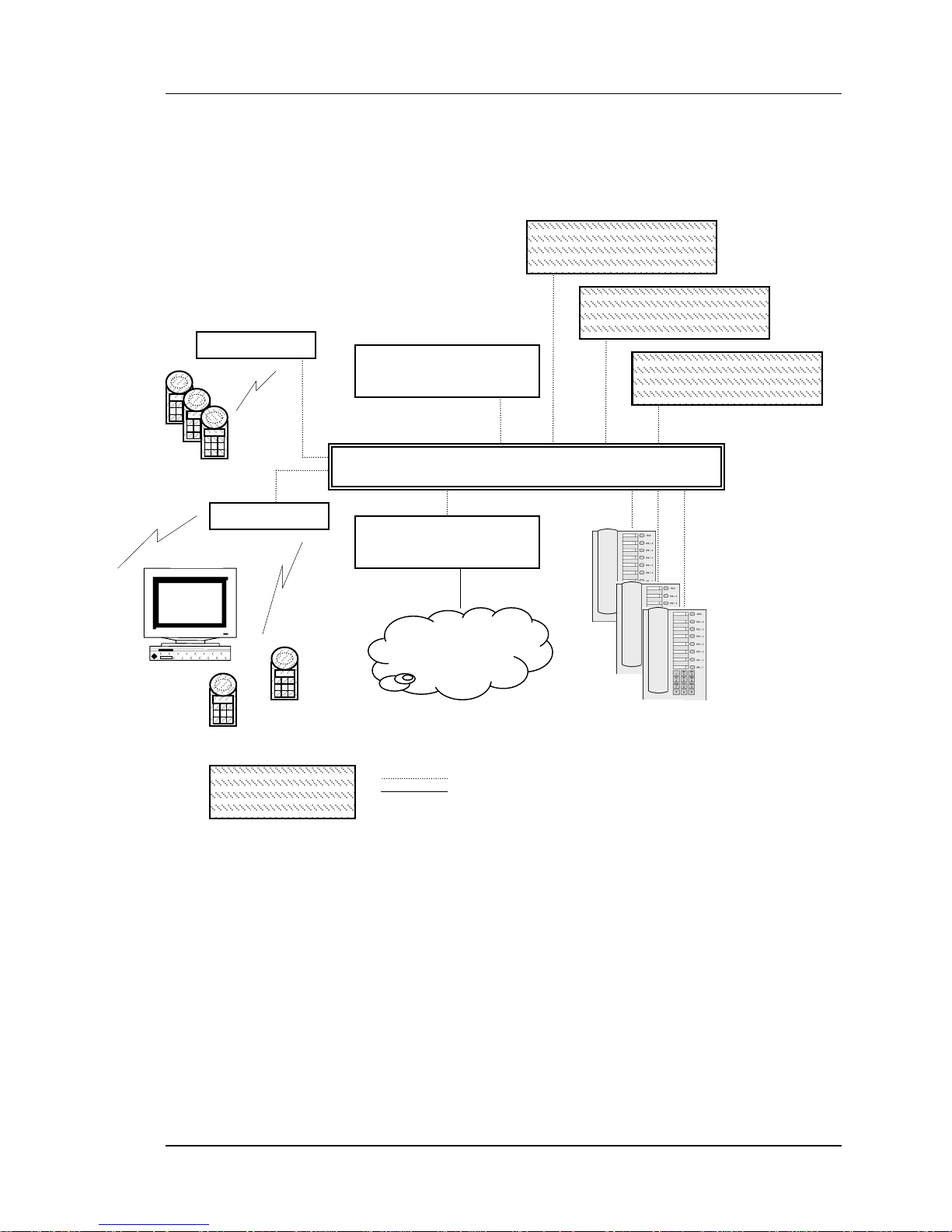
2.6 System Diagram
The following diagram shows the NetLink SVP Server residing on a network with an IP
telephony server, wireless LAN access points, and Ethernet switch:
NetLink SVP Server
Maste
NetLink SVP Server
IP Telephony
NetLink SVP Server
(showing
optional
multiple
SVP
Servers)
Wireless
Telephones
Serve
Ethernet switch
optional
Wireless
POS
Device supplied by
SpectraLink
IP Gateway
PSTN
or
PBX
IP
Phones
Ethernet cable
Phone cable
(IP telephony system example)
Part Number: 72-0178-00-J.doc Page 12
Page 13

SpectraLink Corporation Installation, Setup, and Maintenance
A
NetLink SVP Server
dministrative
computer
access point
NetLink SVP Server
Ethernet Switch
Wireless
Telephones
access point
optional
Wireless
POS
CAT 5 cable
25 pair cable
Multiple phone cables
Phone cable
Device supplied by
SpectraLink
NetLink Telephony
Gateway
NetLink Telephony
Gateway
NetLink Telephony
Gateway
NetLink Telephony
Gateway
NetLink Telephony
Gateway
Demarc block
PBX
(NetLink Telephony Gateway system example)
Part Number: 72-0178-00-J.doc Page 13
desksets
Page 14

SpectraLink Corporation Installation, Setup, and Maintenance
NetLink SVP Server
2.7 System Components
• NetLink e340 and i640 Wireless Telephones – Employees can carry Wireless
Telephones to make and receive calls as they move throughout the building. The
Wireless Telephones are to be used on-premises; they are not cellular or satellite
phones. They are connected to the facility's existing telephone system and to the
NetLink Telephony Gateway or IP gateway. Just like wired telephones, they can
receive calls directly, receive transferred calls, transfer calls to other extensions, and
make outside and long distance calls (subject to the restrictions applied in your
facility.)
The NetLink e340, h340 Wireless Telephone is a lightweight, durable handset
specifically designed for mobile workplace use within a facility. The NetLink i640
Wireless Telephone offers a durable design with push-to-talk functionality.
NetLink Wireless Telephones can operate on an 802.11b wireless network and can
operate at a transmission rate of up to 11Mb/s.
• NetLink Telephony Gateway – serves as the connecting point, or gateway, between
the LAN and the existing telephone system. One or more NetLink Telephony
Gateways are typically installed in the telephone equipment room. Each NetLink
Telephony Gateway supports up to 16 telephone lines and Wireless Telephones. Up
to 40 NetLink Telephony Gateways can be connected to the LAN to support
additional telephone lines. If five or more NetLink Telephony Gateways are
connected to the LAN, a NetLink SVP Server must be installed to handle the
increased call volume.
SpectraLink offers digital NetLink Telephony Gateways that work with the digital
ports on most common brands of telephone systems (PBX or key systems). We also
offer an analog NetLink Telephony Gateway that works with telephone systems (CO,
PBX, or Key Systems) with analog (loop start) ports.
• Access Points – supplied by third party vendors, access points provide the
connection between the wired Ethernet LAN and the wireless (802.11) LAN. Access
points (AP) must be positioned in all areas where Wireless Telephones will be used.
The number and placement of access points will affect the coverage area and capacity
of the wireless system. Typically, the requirements for use of NetLink Wireless
Telephones are similar to that of wireless data devices. Contact SpectraLink, or a
certified SpectraLink distributor, for specific information about your facility’s needs.
The NetLink system must connect to access points that utilize SpectraLink Voice
Priority (SVP). Contact SpectraLink, or a certified SpectraLink distributor, to verify
that your AP and its software version are supported.
• Ethernet Switch – a component in the wired Ethernet LAN infrastructure. Switches
interconnect multiple network devices, including access points and NetLink
Telephony Gateways. Ethernet switches are required to provide the higher
performance network connections needed to handle combined voice and data traffic.
Part Number: 72-0178-00-J.doc Page 14
Page 15

SpectraLink Corporation Installation, Setup, and Maintenance
NetLink SVP Server
• Router – an optional component in the wired Ethernet LAN infrastructure that
separates a wired LAN into segments so that network traffic is restricted to those
segments that are directly involved in the communication. Installation of a network
router is recommended in larger networks, where there may be significant network
traffic not related to the wireless LAN. A router will isolate the wireless LAN from
the associated wired LAN so that they are not impacted by each others’ traffic. The
NetLink Telephony Gateways, the APs, and their associated Ethernet switch must all
be on the same “side” of the router.
• NetLink SVP Server – the NetLink SVP Server manages call network traffic. It is a
required component to utilize the 11Mb/s maximum transmission speed available in
the NetLink Wireless Telephone. It is required in any system when five or more
NetLink Telephony Gateways are connected to the LAN. With 40 NetLink Telephony
Gateways cabled together, the NetLink SVP Server supports a maximum of 640
telephone lines and 120 simultaneous Wireless Telephone calls.
SpectraLink Voice Priority (SVP) is the SpectraLink quality of service (QoS)
mechanism that is implemented in the Wireless Telephone and AP to enhance voice
quality over the wireless network. SVP gives preference to voice packets over data
packets on the wireless medium, increasing the probability that all voice packets are
transmitted efficiently and with minimum or no delay. SVP is fully compliant with
the IEEE 802.11 and 802.11b standards.
• Administrative computer – Required for setup and maintenance of the NetLink
Telephony Gateway and the NetLink SVP Server. This computer may be temporarily
connected directly to the component or to the network, a dedicated computer is not
required. Some installations use a laptop to configure and maintain system
components.
• TFTP Server – Required in an IP system to distribute software to the Wireless
Telephones and SVP Server. May be on a different subnet than the IP gateway, IP
telephony server, and APs.
Part Number: 72-0178-00-J.doc Page 15
Page 16

SpectraLink Corporation Installation, Setup, and Maintenance
NetLink SVP Server
2.8 The Front Panel of the NetLink SVP Server
The NetLink SVP Server’s front panel contains ports to connect to power, the LAN, and
an administrative computer via an RS-232 port. Status LEDs supply information about
the NetLink SVP Server’s functioning.
S
RS-232
L
A
N
K
O
K
C
C
O
T
L
NETWORK
E
R
R
O
R
3 4 5 1 2
Status
RS-232 Port – male DB-9 connector (DTE) used for RS-232 connection to a terminal,
terminal emulator, or modem for system administration.
LEDs:
LNKOK – lit when there is a network connection.
– lit if there is system activity.
ACT
– lit if there are network collisions.
COL
NETWORK
ERROR – lit when the system has detected an error.
STATUS – indicate system error messages and status.
– connects to wired (Ethernet) LAN.
1 – heartbeat, indicates gateway is running.
PWR
2 – if active calls.
3, 4, 5 – currently unused
PWR (power jack) – connects to the AC adapter supplying power to the system.
Use only the SpectraLink-provided Class II AC Adapter with output
24VDC, 1A.
Part Number: 72-0178-00-J.doc Page 16
Page 17

SpectraLink Corporation Installation, Setup, and Maintenance
NetLink SVP Server
3. Installing the NetLink SVP Server
As shown in the system diagram the NetLink SVP Server is connected to the Ethernet
switch. The specifications covered here allow for great flexibility in physical placement
of the components within stated guidelines.
See the Setup and Administration document for your vendor’s IP system for information
on LAN requirements, network infrastructure and IP addressing.
3.1 Required Materials
The following equipment must be provided by the customer.
Power Outlet – must accept SpectraLink provided AC adapter.
Backboard space – the NetLink SVP Server is designed to be wall mounted to
¾” plywood securely screwed to the wall.
Screws – required to mount the NetLink SVP Server to the wall. Four #8 - ¾”
panhead wood screws (or similar device) are required.
Cat. 5 Cable – RJ-45 connector at the NetLink SVP Server. Connection to
Ethernet switch.
3.2 Locate the NetLink SVP Server
The NetLink SVP Server measures approximately 4 x 12.5 x 7 inches, and weighs about
five pounds. The unit can be wall mounted, vertically or horizontally, over ¾” plywood.
The SVP Server can also be rack mounted using a rack mount kit (sold separately).
Locate the NetLink SVP Server in a space with:
• Sufficient backboard mounting space (for wall mount) and proximity to the LAN
access device (switched Ethernet hub) and power source.
• Easy access to the front panel, which is used for cabling.
• A maximum distance of 325 feet (100 meters) from the Ethernet switch.
3.3 Install the NetLink SVP Server
Mount the SVP Server to rack
The rack mount kit is designed for mounting equipment in a standard 19 inch rack and
should contain the following equipment:
• Mounting plates – two for each SVP Server to be mounted.
• Screws – four rack mount screws for each SVP Server to be mounted.
To rack mount the NetLink SVP Server:
1. Remove the corner screws from the SVP Server
2. Screw the U-shaped
SVP Server.
Part Number: 72-0178-00-J.doc Page 17
end (round screw holes) of the two mounting plates to the
Page 18

SpectraLink Corporation Installation, Setup, and Maintenance
NetLink SVP Server
3. Screw the other end of the two mounting plates (oblong screw holes) to the rack.
4. Repeat steps 1-3 for each additional SVP Server. The mounting plate is designed
to provide the correct minimum spacing between units. When mounting multiple
units, stack the units in the rack as closely as possible.
Mount the NetLink SVP Server to wall
The NetLink SVP Server can be mounted either horizontally or vertically.
To mount the NetLink SVP Server:
1. Using a 1/8 inch drill bit, drill four pilot holes, on 1.84 by 12.1 inch centers
(approximately equivalent to 1-13/16 inch by 12-1/8 inch).
2. Insert the #8 x 3/4 inch screws in the pilot holes and tighten, leaving a 1/8 to 1/4
inch gap from the wall.
Connect NetLink SVP Server to LAN
Using a Cat. 5 cable, connect the NETWORK port on the NetLink SVP Server to the
connecting port on the Ethernet switch.
Connect Power
1. Connect the power plug from the AC adapter to the jack labeled PWR on the
NetLink SVP Server.
Use only the provided Class II AC Adapter with output 24VDC, 1A.
2. Plug the AC adapter into a 110VAC outlet to apply power to the NetLink SVP
Server.
3. The system will cycle through diagnostic testing and the LEDs will blink for
about one minute. When the system is ready for use:
• The
•
After the NetLink SVP Server is installed, you must configure the NetLink Wireless
Telephones. For Wireless Telephone configuration, see the Setup and Administration
document for your vendor’s IP system.
ERROR LED should be off.
Status 1 should be blinking.
Part Number: 72-0178-00-J.doc Page 18
Page 19

SpectraLink Corporation Installation, Setup, and Maintenance
NetLink SVP Server
4. Configuring the NetLink SVP Server
During initial setup of the NetLink SVP Server the IP address is established and the
maximum number of active calls per access point is set. Optionally, you may enter a
hostname and a location for software updates via TFTP.
4.1 Connecting to the NetLink SVP Server
The initial connection to the NetLink SVP Server must be made via a serial connection to
establish the NetLink SVP Server’s IP address. After the IP address is established,
connection to the NetLink SVP Server may be done via the network using Telnet. It is
recommended that the basic setup actions occur while the serial connection is made.
Connect via the Serial Port
1. Using a DB-9 female, null-modem cable, connect the NetLink SVP Server to the
serial port of a terminal or PC.
2. Run a terminal emulation program (such as HyperTerminal™) or use a VT-100
terminal with the following configuration:
Bits per second: 9600
Data bits: 8
Parity: None
Stop bits: 1
Flow control: None
3. Press Enter to display the NetLink SVP Server login screen.
4. Enter the default login: admin and default password: admin. These are case
sensitive.
5. The NetLink SVP-II System menu will display.
Connecting Via Telnet
Telnet can only be used after the NetLink SVP Server’s IP address
The Telnet method of connection is used for routine maintenance of the NetLink Server
for both local and remote administration, depending on your network.
To connect via Telnet, run a Telnet session to the IP address of the NetLink SVP Server.
Once you connect and log in, the
is configured.
NetLink SVP-II System menu displays.
Part Number: 72-0178-00-J.doc Page 19
Page 20

SpectraLink Corporation Installation, Setup, and Maintenance
NetLink SVP Server
4.2 The NetLink SVP-II System Menu
The main menu displays as shown here:
System Status – menu for viewing error messages, status of operation and software
code version.
SVP-II 2 Configuration – allows you to set the mode and reset the system.
Network Configuration – allows you to set network configuration options, including IP
address and hostname.
Change Password – allows you to change the password for NetLink SVP Server access.
2
SVP-II is a designation used internally by SpectraLink Engineering.
Part Number: 72-0178-00-J.doc Page 20
Page 21

SpectraLink Corporation Installation, Setup, and Maintenance
NetLink SVP Server
4.3 Network Configuration
The IP address and other network settings are established via the Network
Configuration
enter the IP address of the location of any software updates you may obtain from
SpectraLink. See section 5, the Software Maintenance section, of this document for more
information about installing software updates via TFTP.
screen. This is also where you may optionally establish a hostname and
Scroll to
Network Configuration and select by pressing Enter. A screen similar to the
following appears:*
*
• IP Address – enter the IP address of the NetLink SVP Server, defined by
your network administrator. Enter the complete address including digits and
periods.
DHCP may be entered.
A “master” SVP Server must have a static IP address.
• Hostname -(optional) change the default host name, if desired. This is the
name of the NetLink SVP Server to which you are connected, for
identification purposes only. You cannot enter spaces in this field.
•
SVP-II TFTP Download Master – this entry indicates the source of software
updates for the NetLink SVP Server. See section 5, the Software Maintenance
section, for more information.Valid source location entries are:
NONE – disables.
*
The S=SendAll option is available only in IP system configurations.
Part Number: 72-0178-00-J.doc Page 21
Page 22

SpectraLink Corporation Installation, Setup, and Maintenance
NetLink SVP Server
IP Address – the IP address of a network TFTP server that will be used to
transfer software updates to the NetLink SVP Server.
• DNS server and DNS domain – These settings are used to configure Domain
Name services. Consult your system administrator for the correct settings.
These can also be set to DHCP. This will cause the DHCP client in the
NetLink SVP Server to attempt to automatically get the correct setting from
the DHCP server. The DHCP setting is only valid when the IP address is also
acquired using DHCP.
• WINS servers – These setting are used for Windows Name Services. Consult
your system administrator for the correct settings. These can also be set to
DHCP. This will cause the DHCP client in the NetLink SVP Server to attempt
to automatically get the correct setting from the DHCP server. The DHCP
setting is only valid when the IP address is also acquired using DHCP.
When the name services are set up correctly, the NetLink SVP Server can
translate hostnames to IP addresses. Using Telnet, it is also possible to
access the NetLink SVP Server using its hostname instead of the IP
address.
• Workgroup – as set in WINS.
• Syslog Server – Logging can be set to Syslog or NONE. If Syslog is set, a
message is sent to the syslog server when an alarm is triggered.
The NetLink SVP Server must be reset in order to set the configuration options. If the
NetLink SVP Server is in Maintenance Lock, you will be prompted to reset the NetLink
SVP Server upon pressing Esc. Respond with a Y to the reset prompt.
The NetLink SVP Server may be manually reset by selecting the Reset option in the
SVP-II Configuration screen and then pressing Y (Yes).
Send All
In an IP system with multiple NetLink SVP Servers, the SendAll option is provided to
speed configuration and ensure identical settings. The
send that configuration parameter to every NetLink SVP Server on the LAN.
can only be used after the IP address is established on EACH NetLink SVP Server via the
serial connection. If you anticipate identical settings across the LAN, set just the IP
address and custom hostname (if desired) for each NetLink SVP Server using the initial
serial connection. Then connect via the LAN and use SendAll to set identical
configuration options for all NetLink SVP Servers.
SendAll is to be utilized in your system, all passwords must be identical. DO NOT
If
CHANGE THE PASSWORD AT THE INITIAL CONFIGURATION IF THE SEND
ALL OPTION IS DESIRED. Use the default password and change it globally if desired
after a LAN connection is established for all NetLink SVP Servers.
S=SendAll option allows you to
SendAll
If independent administration of each NetLink SVP Server is desired, the passwords may
be set at initial configuration.
Part Number: 72-0178-00-J.doc Page 22
Page 23

SpectraLink Corporation Installation, Setup, and Maintenance
NetLink SVP Server
To change the IP address of the master SVP Server, change it in this menu
and reboot the system. Then you may change alias IP addresses in each of
the other SVP Servers without error.
Part Number: 72-0178-00-J.doc Page 23
Page 24

SpectraLink Corporation Installation, Setup, and Maintenance
NetLink SVP Server
4.4 SVP Server Configuration
The SVP-II Configuration screen is where you set the mode of the NetLink SVP Server.
It is also where you can lock the NetLink SVP Server for maintenance and reset the
NetLink SVP Server after maintenance. The type of gateway you are using determines
the mode of the NetLink SVP Server. For SVP-II Mode, select from either NetLink for
systems using the SpectraLink NetLink Telephony Gateway or NetLink IP for systems
using an IP telephony server from a third party vendor.
The NetLink SVP Server will automatically lock for maintenance if the IP address is
changed. When this Maintenance Lock occurs, the NetLink SVP Server must be reset
upon exit. All active calls are terminated during a reset.
From the main menu, scroll to SVP-II Configuration and select by pressing Enter.
Part Number: 72-0178-00-J.doc Page 24
Page 25

SpectraLink Corporation Installation, Setup, and Maintenance
NetLink SVP Server
NetLink Telephony Gateway System Configuration
The following screen displays the options for the NetLink Telephony Gateway system
configuration:
• SVP-II Mode: Set to NetLink if using a NetLink Telephony Gateway.
• Ethernet link: The SVP Server will auto-negotiate unless there is a need to
specify a link speed.
• System Locked: This option is used to take the system down for
maintenance. The default entry is N (No). Set it at Y (Yes) to prevent any new
calls from starting. Return to N to restore normal operation.
• Maintenance Lock: The system automatically sets this option to Y (Yes) after
certain maintenance activities that require reset, such as changing the IP
address. Maintenance Lock prevents any new calls from starting. Note that the
administrator cannot change this option. It is automatically set by the system.
Reset the system at exit to clear Maintenance Lock.
Inactivity Timeout (min): Set the number of minutes the administrative
•
module can be left unattended before the system closes it. This number can be
from 1 to 100. If it is set to zero (0), the administrative module will not close
due to inactivity.
• QoS Configuration: Select this option to set the DSCP tags and the 802.1p
tags. See QoS Configuration section.
• Reset System: If this option is selected, you will be prompted to reset the
NetLink SVP Server upon exiting this screen.
The NetLink SVP Server should be reset at the end of any
Note that resetting the NetLink SVP Server will terminate any calls in progress.
Part Number: 72-0178-00-J.doc Page 25
maintenance procedure that requires a reset either via Maintenance
Lock
or manually via Reset System.
Page 26

SpectraLink Corporation Installation, Setup, and Maintenance
NetLink SVP Server
IP System Configuration
For an IP system, set the SVP Mode to NetLink IP.
The IP options are shown on the following screen:
• Phones per Access Point: Access point specifications are detailed in the
Configuration Notes for each brand and type. Refer to these notes when
entering the number of simultaneous calls supported for your type.
• 802.11 Rate: Select 1MB/2MB to limit the transmission rate between the
Wireless Telephones and access points. Select Automatic to allow the
Wireless Telephone to determine its rate (up to 11 Mb/s).
• SVP-II Master: The master SVP Server must be identified in an IP system.
Select one of the following identification options:
∗ Statically configure the IP address of the master SVP Server in each of the
SVP Servers. Enter the IP address.
∗ Statically configure the IP address of the master SVP Server in a DHCP
server and configure each of the SVP Servers to get the information from
the DHCP server. Enter DHCP. If DHCP is used, the IP address of the
master SVP Server must be configured in the DHCP server. See the
Wireless Telephone interface document for your IP environment for more
information about DHCP integration factors.
∗ Statically configure the IP address of the master SVP Server in a DNS
server and configure the each of the SVP Servers to retrieve this
information from the DNS server. Enter DNS. If DNS is used, the IP
address of the master SVP Server must be configured in the DNS server.
• First Alias IP Address/Last Alias IP Address: The SVP Server uses an IP
address when acting as a proxy for the Wireless Telephone. Therefore, one
alias IP address is required for every installed NetLink Wireless Telephone.
These IP addresses must be entered as a range and must be assigned solely for
this purpose.
All alias addresses must be on the same subnet as the SVP Server
and cannot be duplicated on other subnets or SVP Servers. There is
no limit to the number of addresses that can be assigned, but the
capacity of each SVP Server is 500 Wireless Telephones.
Part Number: 72-0178-00-J.doc Page 26
Page 27

SpectraLink Corporation Installation, Setup, and Maintenance
NetLink SVP Server
Alias IP Addresses are not necessary in Avaya and Cisco systems.
Enable H.323 Gatekeeper: In certain H.323 protocol systems, the SVP
•
Server may function as a gatekeeper. Enter
as the gatekeeper in the H.323 protocol environment.
See the NetLink Telephony Gateway System Configuration section for an explanation of
the remaining options on this screen.
See the Overview section for an explanation of the master SVP
Server.
QoS Configuration
Tags set packet priorities for QoS.
Y to have the SVP Server function
Either DSCP or 802.1p tags may be used. DSCP tags may be set to a number 0-255.
DSCP Tag – (Differentiated Services Code Point) is a QoS mechanism for
•
setting relative priorities. Packets are tagged with a DSCP field in the IP
header for type of service. The value may be set as a number from 0-255 and
may be different for administration and in call/not in call modes.
• 802.11p Tag –Packets are tagged with a 802.1p field in the Ethernet header
for type of service. The value may be set as a number from 0-255 and may be
different for administration and in call/not in call modes.
Part Number: 72-0178-00-J.doc Page 27
Page 28

SpectraLink Corporation Installation, Setup, and Maintenance
NetLink SVP Server
4.5 Change Password
If desired, the password to access the NetLink SVP Server may be changed. Select
Change Password from the main menu. A screen similar to the following will appear:
Enter the information and either select Set Password or press the S key to set the new
password.
Password parameters:
• More than four characters,
• First character must be a letter,
• Other characters may be numbers or letters,
• No dashes, spaces, or punctuation marks, etc. (alphanumeric only).
If you forget a password, call SpectraLink Customer Service for assistance.
Part Number: 72-0178-00-J.doc Page 28
Page 29

SpectraLink Corporation Installation, Setup, and Maintenance
NetLink SVP Server
5. Swapping/Adding/Deleting SVP Servers
Whenever an SVP Server is removed from the system, Wireless Telephones that are
using the SVP Server will be affected. If the removal of the SVP Server is intentional, the
administrator should lock and idle the system prior to removing an SVP Server.
Whenever an SVP Server is added to the system, the change is seamless and does not
affect Wireless Telephone calling functionality.
5.1 IP System
Adding an SVP Server
In the IP PBX environment, a new SVP Server is detected within two seconds of being
added to the system (booted/configured/connected). When detected, any Wireless
Telephone not active in a call will immediately be forced to check-out and check-in
again. Any Wireless Telephone in a call will immediately switch to the SVP Server that
should provide its "timing" function. This switch should not be noticeable to the user
since it is similar to a normal handoff between access points. When the Wireless
Telephone ends the call, it will be forced to checkout and checkin again.
Removing an SVP Server
When an SVP Server is removed from the system it is detected within two seconds.
Wireless Telephones not in calls are immediately forced to checkout and checkin again.
For Wireless Telephones active in calls, two possible scenarios can occur. If the SVP
Server that was removed was providing the "gateway" function for the Wireless
Telephone, then the call is lost and the Wireless Telephone is forced to checkin again. If
the SVP Server that was removed was providing the "timing" function for the call, the
call will switch to the SVP Server that should now provide the "timing" function. Note
that during the two seconds while the loss of the SVP Server is being detected, the audio
for the call will be lost.
Changing the Master SVP Server
In the event the master SVP Server loses communication with the network, the Wireless
Telephone system will fail. All SVP Servers will lock and all calls will be lost and no
calls will be able to be placed. Therefore, if the master SVP Server needs to be replaced,
be sure the system can be brought down with minimal call interruption. Be sure to reset
all SVP Servers after the master has been replaced. If the IP address of the master is
changed, it must be changed in all SVP Servers.
Part Number: 72-0178-00-J.doc Page 29
Page 30

SpectraLink Corporation Installation, Setup, and Maintenance
NetLink SVP Server
5.2 NetLink Telephony Gateway System
In a NetLink Gateway environment, the addition of an SVP Server is detected as soon as
the new SVP Server is running. The new SVP Server will immediately start providing the
"timing" function for the appropriate Wireless Telephones. The user should not detect
any change. The removal of an SVP Server is detected within one minute. During this
time, any Wireless Telephone that was using the SVP Server that was removed will be
affected. If the Wireless Telephone was not in a call, the Wireless Telephone may lose
contact with its gateway, resulting in a checkout/checkin sequence. If the Wireless
Telephone was in a call, the audio will be lost and the call will be dropped.
There is no master SVP Server in a NetLink Telephony Gateway environment.
Part Number: 72-0178-00-J.doc Page 30
Page 31

SpectraLink Corporation Installation, Setup, and Maintenance
NetLink SVP Server
6. Software Maintenance
The NetLink SVP Server uses proprietary software programs written and maintained by
SpectraLink Corporation. The software versions that are running on the system
components can be displayed via the System Status screen.
SpectraLink or its authorized dealer will provide information about software updates and
how to obtain the software (for example, downloading from a web site).
At startup the NetLink SVP Server uses TFTP to check the software version it is running
against the version in the TFTP location. If there is a discrepancy, the NetLink SVP
Server will download the version in the TFTP location. See the Setup and Administration
document for your vendor’s IP system for more information about using TFTP.
6.1 Software Updates
After software updates are obtained from SpectraLink, they must be transferred to the
TFTP location in the LAN to update the code used by the NetLink SVP Server.
Lock the NetLink SVP Server in the SVP-II Configuration screen prior to updating the
software.
Note that locking the NetLink SVP Server will prevent new calls from
starting. All calls in progress will be terminated when the NetLink SVP
Server is reset.
Part Number: 72-0178-00-J.doc Page 31
Page 32

SpectraLink Corporation Installation, Setup, and Maintenance
NetLink SVP Server
7. Troubleshooting via System Status Menu
Information about system alarms, and network status displays on various screens
accessed through the
NetLink SVP Server. See the previous sections for directions on how to connect to the
NetLink SVP Server and navigate to the
System Status Menu screen, opened from the main menu of the
System Status Menu.
Error Status – displays alarm and error message information.
Network Status – displays information about the Ethernet network to which the NetLink
SVP Server is connected.
Software Versions – lists the software version for each SpectraLink component.
Options on the System Status Menu provide a window into the real time operation of the
components of the system. Use this data to determine system function and to troubleshoot
areas that may be experiencing trouble.
Part Number: 72-0178-00-J.doc Page 32
Page 33

SpectraLink Corporation Installation, Setup, and Maintenance
NetLink SVP Server
7.1 Error Status
The Error Status screen displays any alarms that indicate some system malfunction.
Some of these alarms are easily remedied and others require a call to SpectraLink’s
Customer Support Department.
From the System Status Menu, select Error Status. The screen displays active alarms
on the NetLink SVP Server.
The following table displays the list of alarms and a description of the action to take to
eliminate the alarm.
Alarm Text Action
Maximum payload usage reached Reduce usage, clear alarm
Maximum telephone usage reached Reduce usage, clear alarm
Maximum access point usage reached Reduce usage, clear alarm
Maximum call usage reached Reduce usage, clear alarm
SRP audio delayed Reduce usage, clear alarm
SRP audio lost Reduce usage, clear alarm
No IP address Configure an IP address
Press C to clear all clearable alarms.
Part Number: 72-0178-00-J.doc Page 33
Page 34

SpectraLink Corporation Installation, Setup, and Maintenance
NetLink SVP Server
7.2 Network Status
The NetLink SVP Server is connected to the Ethernet network, referred to as the LAN or
Local Area Network. The information about that connection is provided through the
Network Status screen.
From the
about the Ethernet network. This information can help troubleshoot network problems. A
sample screen is displayed here.
System Status Menu, select Network Status. The screen displays information
Ethernet Address – MAC address of the NetLink SVP Server (hexadecimal).
System Uptime – the number of days, hours and minutes since the NetLink SVP Server
was last reset.
Net – the type of connection to the Ethernet switch currently utilized. See SVP100
Capacity for more information.
Data is transmitted over SpectraLink components by proprietary
technology developed by SpectraLink Corporation. The SpectraLink
Radio Protocol (SRP) packets and bytes can be differentiated from other
types of transmissions and are used to evaluate system functioning by
SpectraLink customer support and engineering personnel.
Part Number: 72-0178-00-J.doc Page 34
Page 35

SpectraLink Corporation Installation, Setup, and Maintenance
NetLink SVP Server
RX – Ethernet statistics concerning the received packets during System Uptime.
bytes – bytes received
packets – packets received
errors – sum of all receive errors (long packet, short packet, CRC, overrun,
alignment)
drop – packets dropped due to insufficient memory
fifo – overrun occurred during reception
alignment – nonoctet-aligned packets (number of bits NOT divisible by eight)
multicast – packets received with a broadcast or multicast destination address
TX – Ethernet statistics concerning the transmitted packets during System Uptime.
bytes – bytes transmitted
packets – packets transmitted
errors – sum of all transmit errors (heartbeat, late collision, repeated collision,
underrun, carrier)
drop – packets dropped due to insufficient memory
fifo – underrun occurred during transmission
carrier – carrier lost during transmission
collisions – packets deferred (delayed) due to collision
SVP-II Access Points in Use – access points in use by Wireless Telephones, either in
standby or in a call ‘Last’ is current, ‘Max’ is the maximum number in use at one time.
SVP-II Access Points in Calls – access points with Wireless Telephones in a call
SVP-II Telephones in Use – Wireless Telephones in standby or in a call
SVP-II Telephones in Calls – Wireless Telephones in a call
SVP-II SRP Audio (Delay) – SRP audio packets whose transmission was momentarily
delayed
SVP-II SRP Audio (Lost) – SRP audio packets dropped due to insufficient memory
resources
Part Number: 72-0178-00-J.doc Page 35
Page 36

SpectraLink Corporation Installation, Setup, and Maintenance
NetLink SVP Server
7.3 Software Version
The NetLink SVP Server and Wireless Telephones utilize SpectraLink Corporation’s
proprietary software that is controlled and maintained through versioning. The
Version
screen provides information about the version currently running on the NetLink
SVP Server. This information will help you determine if you are running the most recent
version and will assist SpectraLink engineering and/or customer support in
troubleshooting software problems.
Software
From the
here.
System Status Menu, select Software Version. A sample screen is displayed
Note that the software versions on your system will be different from the versions
displayed in the above sample screen which shows the 170 series software.
Part Number: 72-0178-00-J.doc Page 36
Page 37

SpectraLink Corporation Installation, Setup, and Maintenance
NetLink SVP Server
7.4 Gatekeeper Database
The Gatekeeper Database screen lists the registered extension numbers and the IP
address currently being used by each.
Alias/Phone Number – phone identifier.
RAS IP address – (Registration Admission Status) IP address.
CSA IP address – (Call Signaling Address) IP address.
Expiration (secs) – the number of seconds until the record will be renewed. A Wireless
Telephone IP address is renewed every 90 seconds.
Press the question mark (shift + ?) to open the H.323 Gatekeeper Database Help
screen: The help screen provides information about how to scroll and search the database.
Part Number: 72-0178-00-J.doc Page 37
Page 38

SpectraLink Corporation Installation, Setup, and Maintenance
NetLink SVP Server
Index
Access point, description, 13
Alarms, 33
Configuration
Initial setup, 21
Customer Support Hotline, 5
Download master, 20
Downloading Software Updates, 31
Error Status, 33
Ethernet switch, description, 13
Hotline, 5
NetLink SVP Server
Front Panel, 15
NetLink SVP Server, 6, 14
Location, 16
Mounting, 16, 17
NetLink SVP Server Alarms, 33
NetLink SVP Server, administration, 18
NetLink Telephony Gateway
Description, 13
Network Status, 34
Power, 16
Serial Connection, 18
Site Preparation, 16
Software Updates, 31
Telnet, 18
TFTP Download Master, 20
Wireless Telephone, description, 13
Part Number: 72-0178-00-J.doc Page 38
 Loading...