

Page 1

Installation and Administration
NetLink Open Applications Interface (OAI) Gateway
Part Number: 72-0078-07
Issue B
Page 2

SpectraLink Corporation Installation and Administration
NetLink OAI Gateway
Notice
SpectraLink Corporation has prepared this document for use by SpectraLink personnel and customers. The
drawings and specifications contained herein are the property of SpectraLink and shall be neither reproduced in
whole or in part without the prior written approval of SpectraLink, nor be implied to grant any license to make,
use, or sell equipment manufactured in accordance herewith.
SpectraLink reserves the right to make changes in specifications and other information contained in this
document without prior notice, and the reader should in all cases consult SpectraLink to determine whether
any such changes have been made.
The terms and conditions governing the sale of SpectraLink hardware products and the licensing of
SpectraLink software consist solely of those set forth in the written contracts between SpectraLink and its
customers. No representation or other affirmation of fact contained in this document including but not limited
to statements regarding capacity, response-time performance, suitability for use, or performance of products
described herein shall be deemed to be a warranty by SpectraLink for any purpose, or give rise to any liability of
SpectraLink whatsoever.
In no event shall SpectraLink be liable for any incidental, indirect, special, or consequential damages
whatsoever (including but not limited to lost profits) arising out of or related to this document, or the
information contained in it, even if SpectraLink has been advised, knew, or should have known of the
possibility of such damages.
Trademark Information
SpectraLink
The SpectraLink logo
LinkPlus
Link
NetLink
SVP
Are trademarks and registered trademarks of SpectraLink Corporation.
All other trademarks used herein are the property of their respective owners.
SpectraLink Corporation
5755 Central Avenue
Boulder, CO 80301
Within the United States, dial
303.440.5330 or
toll free 800.676.5465
Outside the U.S., dial
+1.303.440.5330
www.spectralink.com
Copyright © 1998 to 2006 SpectraLink Corporation. All rights reserved
Information in this document is subject to change without notice and does not represent a commitment on the
part of SpectraLink Corporation. The software described in this document is furnished under a license and/or
copyright and may only be used with the terms of SpectraLink’s software license agreement as found in this
manual or at
used only in accordance with the terms of the agreement. No part of this manual, or the software described
herein, may be reproduced or transmitted in any form or by any means, electronic or mechanical, including
photocopying and recording, for any purpose except for the sole intent to operate the product or without the
express written permission of SpectraLink Corporation.
http://www.spectralink.com/consumer/resources/software_updates.jsp. The software may be
PN: 72-0078-07-B.doc Page 2
Page 3

SpectraLink Corporation Installation and Administration
NetLink OAI Gateway
Note concerning the NetLink SVP Server:
This equipment has been tested and found to comply with the limits for a Class A digital device, pursuant to
Part 15 of the FCC Rules. These limits are designed to provide reasonable protection against harmful
interference when the equipment is operated in a commercial environment. This equipment generates, uses,
and can radiate radio frequency energy and, if not installed and used in accordance with the instruction manual,
may cause harmful interference to radio communications. Operation of this equipment in a residential area is
likely to cause harmful interference in which case the user will be required to correct the interference at his own
expense.
Note concerning shielded cable:
SpectraLink recommends the use of shielded cable for all external signal connections in order to maintain FCC
Part 15 emissions requirements.
Note concerning the NetLink Wireless Telephones:
This device complies with Part 15 of the FCC Rules. Operation is subject to the following two conditions: (1)
This device may not cause harmful interference, and (2) this device must accept any interference received,
including interference that may cause undesired operation.
TUV Rheinland of North America is a Nationally Recognized Testing Laboratory
(NRTL) in the United States and is accredited by the Standards Council of Canada to test
and certify products to Canadian National Standards. Clients can demonstrate compliance
for both U.S. and Canadian markets through a single mark (cTUVus) on their product(s)
which denotes compliance to U.S. and Canadian National Standards.
WARNING: Changes or modifications to this equipment not approved by SpectraLink
Corporation may cause this equipment to not comply with part 15 of the FCC rules and
void the user’s authority to operate this equipment.
WARNING: SpectraLink products contain no user-serviceable parts inside. Refer servicing
to qualified service personnel.
IMPORTANT SAFETY INFORMATION
Follow these general precautions while installing telephone equipment:
• Never install telephone wiring during a lightning storm.
• Never install telephone jacks in wet locations unless the jack is specifically designed for
wet locations.
• Never touch uninsulated telephone wires or terminals unless the telephone line has
been disconnected at the network interface.
• Use caution when installing or modifying telephone lines
Please visit spectralink.com to view regulatory declarations.
PN: 72-0078-07-B.doc Page 3
Page 4

SpectraLink Corporation Installation and Administration
NetLink OAI Gateway
FCC Information
The NetLink Telephony Gateway complies with Part 68, FCC Rules
FCC Registration Number IYGUSA-33816-PX-E
Ringer Equivalence 0.3B
SpectraLink Corporation
NetLink WTS
Made in the USA
This equipment complies with Part 68 of the FCC Rules. On the back of this equipment is a label that contains,
among other information, the FCC Registration Number and Ringer Equivalence Number (REN) for this
equipment. If requested, this information must be given to the telephone company.
This equipment uses RJ-21 connectors.
The REN is useful to determine the quantity of devices you may connect to your telephone line and still have
all of those devices ring when your number is called. In most, but not all, areas, the sum of the RENs of all
devices connected to one line should not exceed five (5.0). To be certain of the number of devices you may
connect to your line, as determined by the REN, you should contact your local telephone company to
determine the maximum REN for your calling area.
If your telephone equipment causes harm to the telephone network, the telephone service may discontinue
your service temporarily. If possible, they will notify you in advance. But if advance notice isn’t practical, you
will be notified as soon as possible. You will be informed of your right to file a complaint with the FCC.
Your telephone company may make changes in its facilities, equipment, operations or procedures that could
affect the proper functioning of your equipment. If they do, you will be notified in advance to give you an
opportunity to maintain uninterrupted telephone service.
If you experience trouble with this telephone equipment, please contact SpectraLink Corporation for
information on obtaining service or repairs.
SpectraLink Corporation
5755 Central Avenue
Boulder, CO 80301
303-440-5330
The telephone company may ask that you disconnect this equipment from the network until the problem has
been corrected or until you are sure that the equipment is not malfunctioning. There are no user serviceable
parts in this equipment.
This equipment may not be used on coin service provided by the telephone company. Connection to party
lines is subject to state tariffs.
PN: 72-0078-07-B.doc Page 4
Page 5

SpectraLink Corporation Installation and Administration
NetLink OAI Gateway
Industry Canada (IC) Notice
Notice:
The Industry Canada (IC) label identifies certified equipment. This certification means that the equipment
meets telecommunications network protective, operational, and safety requirements as prescribed in the
appropriate Terminal Equipment Technical Requirements document(s). The department does not guarantee
the equipment will operate to the user’s satisfaction.
Before installing this equipment, users should ensure that it is permissible to be connected to the facilities of
the local telecommunications company. The equipment must also be installed using an acceptable method of
connection. The customer should be aware that compliance with the above conditions may not prevent
degradation of service in some situations.
Repairs to certified equipment should be coordinated by a representative designated by the supplier. Any
repairs or alterations made by a user to this equipment, or equipment malfunctions, may give the
telecommunications company cause to request the user to disconnect the equipment.
Users should ensure for their own protection that the electrical ground connections of the power utility,
telephone lines and internal metallic water pipe system, if present, are connected together. This precaution may
be particularly important in rural areas.
Caution: Users should not attempt to make such connections themselves, but should contact the appropriate
electric inspection authority, or electrician, as appropriate.
Notice: The Ringer Equivalence Number (REN) assigned to each terminal device provides as indication of the
maximum number of terminals allowed to be connected to a telephone interface. The termination of an
interface may consist of any combination of devices.
REN 0.3B
Approval Numbers:
2128-9760 A
Warranty and Repair Service Center:
SpectraLink Corporation
5755 Central Avenue
Boulder, CO 80301
303-440-5330
DOC Spread Spectrum certification
Wireless Telephone Cert. No. 2128-K1374
PN: 72-0078-07-B.doc Page 5
Page 6

SpectraLink Corporation Installation and Administration
NetLink OAI Gateway
Table of Contents
1. About This Document 7
1.1 Related Documents 7
1.2 Customer Support Hotline 7
1.3 Icons and Conventions 7
2. The NetLink OAI Gateway 8
2.1 System Overview 9
2.2 The NetLink OAI Gateway Front Panel 10
3. Install the NetLink OAI Gateway 11
3.1 Perform Initial Test 11
3.2 Assign the NetLink OAI Gateway’s IP Address 11
3.3 Connect the NetLink OAI Gateway to the LAN 13
3.4 Connect the NetLink OAI Gateway Application Server via RS-232 port 13
3.5 Connect the NetLink OAI Gateway to Application Server via the LAN 14
3.6 Connect the NetLink OAI Gateway to Application Server via a modem 14
4. The Main Menu 15
4.1 NetLink OAI System Main Menu 15
4.2 IP Systems Main Menu 16
5. Configuration Procedures 17
5.1 OAI Box Configuration 18
5.2 Network Configuration 19
5.3 OAI Line Configuration 21
5.4 Telephone Line Configuration 22
5.5 Deleting a Handset 23
5.6 Searching for a Handset 23
5.7 Feature Programming 23
6. Set or Change Password 25
7. System Status Menu 26
7.1 Network Status 27
7.2 Telephone Line Status 29
7.3 Software Versions 30
8. Certification Test 31
9. Software Maintenance 32
9.1 Software Updates for MOG700 Systems 32
9.2 TFTP Software Updates for MOG600 Systems 34
10. Wireless Device Planning Worksheet 35
PN: 72-0078-07-B.doc Page 6
Page 7

SpectraLink Corporation Installation and Administration
NetLink OAI Gateway
1. About This Document
SpectraLink’s Open Application Interface (OAI) enables third-party computer
applications to communicate with SpectraLink’s Wireless Telephones. This
document explains installation of the NetLink OAI Gateway manufactured for the
NetLink Wireless Telephones by SpectraLink Corporation. The NetLink OAI
Gateway provides an interface with an application server on the local area network
(LAN) or RS-232 port. The installation process connects the NetLink OAI Gateway
to an existing LAN.
1.1 Related Documents
NetLink Telephony Gateway: Installation, Configuration, and Administration
(72-0065-02)
Available at http://www.spectralink.com/consumer/resources/manuals.jsp.
NetLink Wireless Telephone: Configuration and Administration
Available at http://www.spectralink.com/consumer/resources/manuals.jsp.
1.2 Customer Support Hotline
SpectraLink wants you to have a successful installation. If you have questions please
contact our Customer Support Hotline at (800) 775-5330. The hotline is open
Monday through Friday, 6 a.m. to 6 p.m. Mountain time.
1.3 Icons and Conventions
This manual uses the following icons and conventions.
Caution! Follow these instructions carefully to avoid danger.
NORM
Note these instructions carefully.
This typeface indicates a key, label, or button on the NetLink OAI
Gateway.
(72-1065-09)
PN: 72-0078-07-B.doc Page 7
Page 8
SpectraLink Corporation Installation and Administration
A
NetLink OAI Gateway
2. The NetLink OAI Gateway
The NetLink OAI Gateway enables third-party applications to communicate directly
with up to 10,000 NetLink Wireless Telephones, allowing users to retrieve and
respond to information using their handsets.
The NetLink OAI Gateway is available in two models and several scaled capacity
levels, please be sure that the OAI Gateway being configured has the appropriate
capacity for your implementation.
SpectraLink Model
Number
MOG600 64
MOG710 128
MOG720 256
MOG730 512
MOG740 1,024
MOG750 10,000
Maximum
Number of
Users
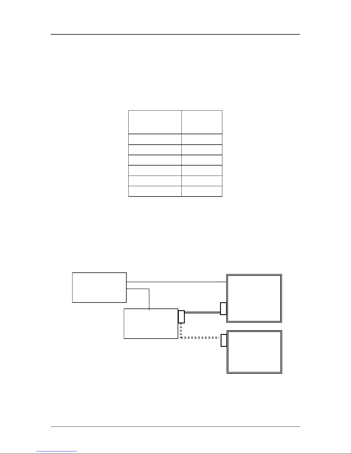
As shown in the diagram below, a single NetLink OAI Gateway is connected to the
site’s Local Area Network (LAN) via an Ethernet switch. The connection to the
OAI Application Server can be accomplished by a direct connect (RS-232) or
through the Ethernet connection, but may run only via one connection at a time.
During setup, the IP address of the NetLink OAI Gateway must be set. Once the IP
address is established, the Gateway can be accessed by the application server via the
RS-232 port or the LAN via telnet.
LAN
Ethernet
switch
OAI
Gateway
RS 232 cable
for ongoing
operation
RS-232
port
Application
Server
(PC)
RS-232
port
PN: 72-0078-07-B.doc Page 8
lternate RS 232
cable for initial
setup
RS-232
port
Configuration
Terminal
(PC)
Page 9
SpectraLink Corporation Installation and Administration
A
A
t
d
(
d
d
NetLink OAI Gateway
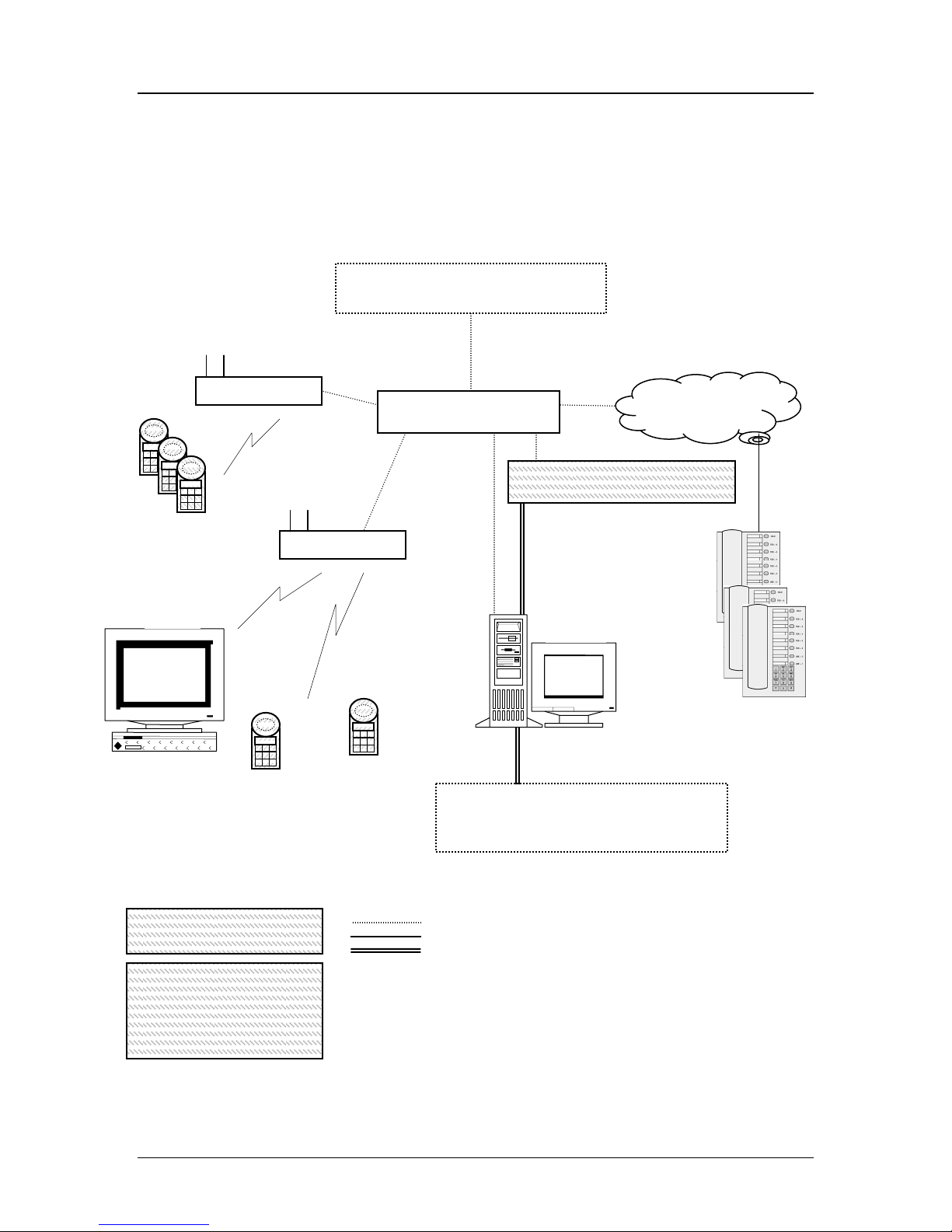
2.1 System Overview
At a typical site, the NetLink OAI Gateway is connected to the Ethernet switch via
an RJ-45/Category 5 cable and the application server via the RS-232 port. The client
system may include a LAN and its application server with a TAP connection to a
communications device such as a paging controller.
Wireless
Telephones
optional
Wireless
Data Device
ccess Point
LAN-based 3
r
Party Applications:
Email Server, LAN Clients, Internet
LAN
Backbone
Ethernet switch
ccess Poin
Wired telephone
system*
NetLink OAI Gateway
OAI protocol
RS 232
Party OAI
Application
r
Server for 3
Wired
Telephones
RS 232
r
Party Applications
Device supplied by
SpectraLink
Direct Connect 3
Paging Controller, Nurse Call Systems,
Industrial Controllers
See Application Note for Specific Installation)
Ethernet cable
Phone cabling
RS-232 cable
* Note that the wired
telephone system may
include a NetLink
Telephony Gateway
Supplied by SpectraLink
PN: 72-0078-07-B.doc Page 9
Page 10
SpectraLink Corporation Installation and Administration
NetLink OAI Gateway
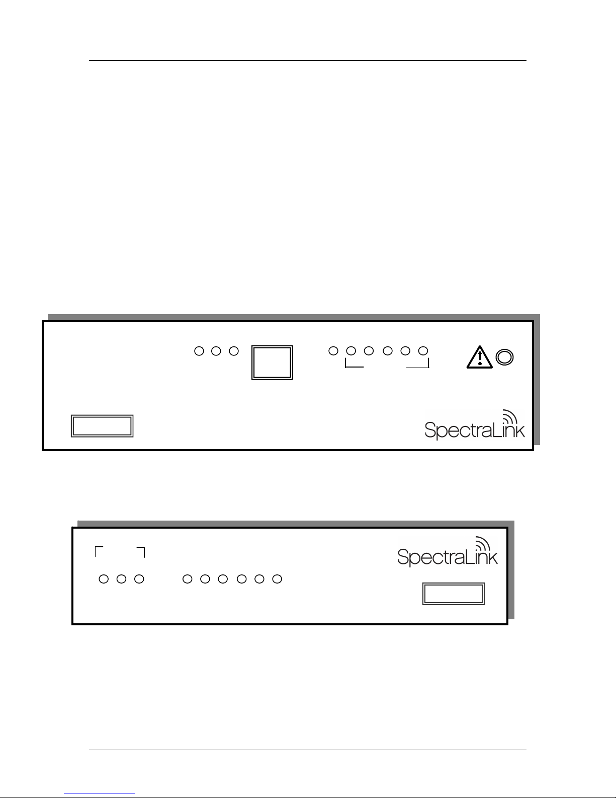
2.2 The NetLink OAI Gateway Front Panel
There are two different models with similar front panel indicators
Network Link LEDs:
(L)NKOK Lit when there is a network connection, i.e. LINK OK.
(A)CT Lit if there is system activity.
(C)OL Lit if there are network collisions.
(E)rror LED: Lit when the system has detected an error.
Status LEDs: indicate system messages and status.
1 Heartbeat, indicates NetLink OAI Gateway is running.
2, 3, and 4 Currently unused
5 System master
RS-232 port
Offered in scaled increments to support up to 10,000 users.
NET
L A C 3 4 5E 1 2
L
A
N
K
O
K
C
C
O
L
T
NETWORK
E
R
R
O
R
STATUS
Model MOG7xx.
RS-232 port
Model MOG6xx
Supports up to 64 users.
The power jack and network port are located on the back of this model.
PN: 72-0078-07-B.doc Page 10
Page 11

SpectraLink Corporation Installation and Administration
NetLink OAI Gateway
3. Install the NetLink OAI Gateway
Place the NetLink OAI Gateway on a shelf or other predetermined location. The
Gateway is only physically connected to the Ethernet switch and may be placed in
any convenient location.
3.1 Perform Initial Test
1. Connect the power plug from the NetLink OAI Gateway’s power adapter to the
power jack on the front (or rear) of the Gateway box.
Use only the adapter ordered from SpectraLink.
2. Plug the power adapter into an outlet or outlet strip.
3. Apply power to the Gateway.
• The
• LED
New System Installation
If this is a new system installation, place, power up and test the OAI Gateway when
the rest of the system is tested. See the
Telephone
Installing in an Existing System
If you are adding OAI to an existing system, the entire system will need to be reset
before the NetLink OAI Gateway can be used. See the
NetLink Wireless Telephone
ERROR LED should be off.
1 should be blinking.
Setup and Maintenance: NetLink Wireless
document for your system for more information.
document for your system for more information.
3.2 Assign the NetLink OAI Gateway’s IP Address
You can administer the NetLink OAI Gateway via Telnet connection from the
NetLink Administration Console. However, as with the Telephony Gateways, the
NetLink OAI Gateway must be assigned an IP address before you can connect using
Telnet.
The following steps outline the procedure to assign the IP address to the NetLink
OAI Gateway.
Setup and Maintenance:
PN: 72-0078-07-B.doc Page 11
Page 12

SpectraLink Corporation Installation and Administration
NetLink OAI Gateway
1. Connect a terminal or PC to the Gateway’s serial port using a cable that
conforms to RS-232 standards for DTE to DTE connections (known as a null
modem cable).
LAN
Ethernet
switch
OAI
Gateway
RS-232
port
RS-232
port
(terminal)
2. Reset the system. The following OAI command will display on the terminal:
04830130.
3. Type the following command on the terminal or PC keyboard:
0255CC [CTRL-M] [CTRL-J].
Note that this command will not display on the screen as it is typed.
4. The
Login prompt should display. If you made an error entering the command
string, the message for “Ill Formed Packet” will display (a series of numbers
followed by some version of the command you typed.) Repeat Steps 2 and 3
until you see the Login prompt.
5. At the Login prompt, enter the default login: admin and default password: admin.
These are case sensitive.
6. You can now configure the NetLink OAI Gateway (including IP address)
following the procedure explained in the next section.
Changing the IP Address
When utilizing the serial port as the primary communication link with the application
server, the OAI command described in step two above must be entered to free the
port and allow it to be used for administrative purposes.
The procedure for entering/changing the IP address of the NetLink OAI Gateway is
described below in section 4.2
When the NetLink OAI Gateway has been configured, disconnect the terminal or
PC from the serial port, reconnect the communication cable between the NetLink
OAI Gateway and the application server, and reset the system. Normal
communication between the application server and OAI Gateway will resume.
PN: 72-0078-07-B.doc Page 12
IP Systems Main Menu
.
Page 13

SpectraLink Corporation Installation and Administration
NetLink OAI Gateway
3.3 Connect the NetLink OAI Gateway to the LAN
1. Using an RJ-45 cable, connect the NETWORK port of the Gateway to the
connecting port on the Ethernet switch.
2. Power up the entire system. Any components should go through their usual
diagnostic routine.
3.4 Connect the NetLink OAI Gateway Application Server via RS-232 port
Some applications or systems may require an RS-232 connection between the
application server and the NetLink OAI Gateway. If your applications have the
ability to communicate OAI messages over TCP/IP, and do not require a serial
connection, the RS-232 cabling is not required and you may use the LAN connection
(port 5456) via the Ethernet switch for your applications.
Connect the application server to the Gateway’s serial port using a cable that
conforms to RS-232 standards for DTE to DTE connections (sometimes called a
null modem cable).
LAN
Ethernet
switch
OAI
Gateway
RS-232
port
Application
Server
(PC)
RS-232
port
The NetLink OAI Gateway uses the following pins on the connector:
Pin Function
1 Carrier Detect
2 Data OAI Receives
3 Data OAI Transmits
5 Ground
7 Ready To Send
8 Clear to Send
PN: 72-0078-07-B.doc Page 13
Page 14
SpectraLink Corporation Installation and Administration
p
NetLink OAI Gateway
3.5 Connect the NetLink OAI Gateway to Application Server via the LAN
Some applications or systems may require a LAN connection between the
application server and the NetLink OAI Gateway. If your applications do not require
a LAN connection, you may use the RS-232.
The IP address must be set for the NetLink OAI Gateway to function on the LAN.
Follow the application’s instructions to identify the Gateway to the application.
LAN
Ethernet
Application
switch
OAI
Gateway
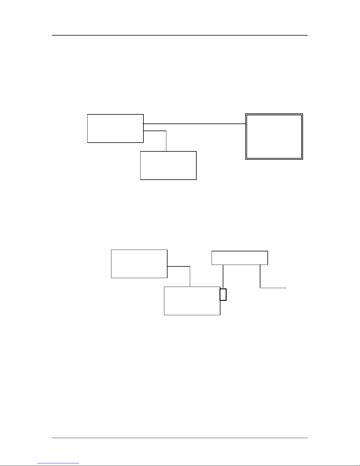
3.6 Connect the NetLink OAI Gateway to Application Server via a modem
In some situations, a modem is used for remote administration of the NetLink OAI
Gateway.
Connect the modem to the Gateway’s serial port using a cable that conforms to RS232 standards for DTE to DCE connections.
LAN
Ethernet
switch
OAI
Gateway
RS-232
port
modem
DCE
Dedicated
hone line
DTE
Server
(PC)
PN: 72-0078-07-B.doc Page 14
Page 15

SpectraLink Corporation Installation and Administration
T
NetLink OAI Gateway
4. The Main Menu
To connect to the NetLink OAI Gateway, select the host name or IP address of the
Gateway from the
The NetLink OAI System menu displays:
4.1 NetLink OAI System Main Menu
Gateway Connection Selection screen.
FTP Server Download Configuration *
This is the default main menu of the OAI Administration console. This menu may
change when the configuration procedure is completed, depending on the OAI
Gateway and the type of system. See following page for the IP systems main menu.
* Note that if the OAI Gateway is a MOG6xx model, the
Configuration option appears on the default main menu.
TFTP Server Download
PN: 72-0078-07-B.doc Page 15
Page 16

SpectraLink Corporation Installation and Administration
NetLink OAI Gateway
4.2 IP Systems Main Menu
One the configuration procedure is completed; the IP System menu adds a Feature
Programming option. Additionally, the OAI Line Configuration option is replaced by a
Telephone Line Configuration option.
PN: 72-0078-07-B.doc Page 16
Page 17

SpectraLink Corporation Installation and Administration
NetLink OAI Gateway
5. Configuration Procedures
The OAI Gateway must be configured according to the type of system in use:
NetLink Telephony Gateway system or IP system. If the NetLink OAI Gateway is
being used in an IP phone system, the configuration proceeds independently of the
IP system. If the system is using one or more NetLink Telephony Gateways, the
OAI Gateway will communicate with them during configuration and operation.
These configuration procedures should be done after the handsets have been
configured in the NetLink Telephony Gateway.
Generally, configuration follows these steps:
1. Establish type of system through OAI Box Configuration option,
2. Establish Network settings through
3. Configure the handsets through either
Network Configuration option,
OAI Line Configuration for NetLink
Gateway systems or through Telephone Line Configuration option for IP systems.
4. (IP systems) Use the Feature Programming option to configure the function
sequence that activates the OAI feature. (In NetLink Telephony Gateway
systems, the OAI function sequence is programmed in the Telephony Gateway).
PN: 72-0078-07-B.doc Page 17
Page 18

SpectraLink Corporation Installation and Administration
NetLink OAI Gateway
5.1 OAI Box Configuration
From the NetLink OAI System menu, select OAI Box Configuration. The following screen
displays.
*
** Option appears only on MOG6xx model.
* Option appears only on NetLink Telephony Gateway systems (when Use NetLink
GW with mogX00 is set to Yes).
Enter configuration information for the NetLink OAI Gateway. Your LAN
administrator should provide this information.
• Use NetLink GW with mogX00 If you are using NetLink Telephony
Gateway(s) in your system, change this option to Yes.
Note: mogX00 is a model designation for the OAI Gateway.
• TFTP Download Master Enter the IP address of the TFTP server.
• Maintenance Lock The system sets this option to
Yes when the system needs
to be reset. Note that the administrator cannot change this option. It is
automatically set by the system after certain maintenance activities that require
reset, and will not return to
No until the system is reset. During Yes, OAI is
inoperable by users.
• Reset System If this option is set to
Yes, the NetLink OAI Gateway will be
reset after pressing ENTER.
PN: 72-0078-07-B.doc Page 18
Page 19

SpectraLink Corporation Installation and Administration
NetLink OAI Gateway
• Reset All Systems: If this option is set to Yes, all system NetLink Telephony
Gateways will be reset after pressing Enter.
5.2 Network Configuration
From the NetLink OAI System menu, select Network Configuration. A screen similar to
the following displays:
*
* Allow FTP Connections option appears on MOG 7xx model only
Enter configuration information for the NetLink OAI Gateway. Your LAN
administrator should provide this information.
• Ethernet Address This is the MAC address of the gateway, set at the factory
and not user configurable.
• IP Address Established in the initial serial connection and may be changed as
needed. The IP address of the NetLink OAI Gateway, defined by your network
administrator. Enter the complete address including digits and periods. DHCP
should not be used with IP OAI.
• Hostname Change the default host name, if desired. This is the name of the
gateway to which you are connected, for identification purposes only. You
cannot enter spaces in this field.
• Subnet Mask Enter the subnet mask defined by the Network Administrator.
• Default Router DHCP or static IP address
PN: 72-0078-07-B.doc Page 19
Page 20

SpectraLink Corporation Installation and Administration
NetLink OAI Gateway
• Allow Telnet Connections Enter Y (yes) to allow connection to the NetLink
OAI Gateway via Telnet; enter
N (no) if you do not want to allow Telnet
connection.
• Allow FTP Connections
Yes/No * (MOG 7xx only)
• DNS server and DNS domain These settings are used to configure Domain
Name services. Consult your system administrator for the correct settings. These
can also be set to DHCP. This will cause the DHCP client in the Gateway to
attempt to automatically get the correct setting from the DHCP server. The
DHCP setting is only valid when the IP address is also acquired using DHCP.
• WINS servers These setting are used for Windows Internet Name Services.
Consult your system administrator for the correct settings. These can also be set
to DHCP. This will cause the DHCP client in the gateway to attempt to
automatically get the correct setting from the DHCP server. The DHCP setting
is only valid when the IP address is also acquired using DHCP.
When the name services are set up correctly, the NetLink OAI Gateway
can translate hostnames to IP addresses. When using Telnet, it is also
possible to access the OAI Gateway using its hostname instead of the IP
address.
• Logging and Log server Logging can be set to
Syslog or NONE. The log server
is the IP address or hostname of the syslog server on the network. The gateway
will output syslog format diagnostic messages. This is usually not needed.
• SNTP server Can be set to a hostname, IP address or
NONE. The SNTP server
is a simple network time server. The OAI Gateway will get the current date and
time from the SNTP server. It will tag syslog messages with the date.
• IGMP Enabled Yes/No. IGMP is the Internet Group Routing Protocol. IGMP
Enabled
allows the OAI Gateway to join multicast groups. If the network switch
connected to the OAI Gateway requires IGMP for multicast traffic to be
forwarded this should be enabled.
• Maintenance Lock The system automatically sets this option to
Yes after
certain maintenance activities that require reset. These are indicated in this list
with an arrow bullet.
Maintenance Lock prevents any new calls from starting. Note
that the administrator cannot change this option. It is automatically set by the
system. Reset the system at exit to clear Maintenance Lock.
Press Esc to return to the NetLink OAI System menu.
PN: 72-0078-07-B.doc Page 20
Page 21

SpectraLink Corporation Installation and Administration
NetLink OAI Gateway
5.3 OAI Line Configuration
In a NetLink Telephony Gateway system, each telephone line using OAI must be
associated with the line and port of its NetLink Telephony Gateway. This procedure
tells the OAI Gateway which handset lines are associated with each NetLink
Telephony Gateway. Any changes made to telephone line configurations on the
NetLink Telephony Gateway, must also be made here on the OAI Gateway.
From the NetLink OAI System menu, select OAI Line Configuration. A screen similar to
the following displays:
Enter the Hostname of the NetLink Telephony Gateway. The OAI Gateway will fill
in the hostname and port number based on the last entry. Simply press Enter to
accept the default port number and
Telephony Gateway is active on the network, the IP address field will be updated
automatically.
Configure all the lines in your system. Use the arrow keys to move the cursor. Note
that the lines will wrap at the top and bottom.
Press Esc to return to the NetLink OAI System menu.
Use S=Search to find boxes in the OAI line configuration.
Hostname as you continue to the next line. If the
PN: 72-0078-07-B.doc Page 21
Page 22

SpectraLink Corporation Installation and Administration
NetLink OAI Gateway
5.4 Telephone Line Configuration
In an IP system, each handset that is to use OAI features must be configured with its
line number and MAC address. Optionally the name and extension number of the
handset user may be entered.
The system will not allow you to register the same handset to two different lines. Use
Esc to cancel out of any unwanted transaction.
Use the arrow keys to navigate to the name and extension fields and enter the
associated data.
• MAC Address The MAC address is printed on the sticker underneath the
battery on the handset. It can also be displayed on the handset by turning off the
handset, and then pressing and holding the
address appears on the first line of the display (12 characters).
The MAC address must be manually entered by typing the entire address
including digits and colons.
• Name Enter the user name assigned to the telephone. This is for record
keeping only; it does not communicate the name to the PBX or the handset.
• Extension Enter the extension assigned to this telephone. This is for record
keeping only; it does not communicate the extension to the PBX or the handset.
Write the MAC address on the Wireless Planning Device Worksheet.
Repeat steps 2, 3, and 4 for each handset to be added or changed.
PN: 72-0078-07-B.doc Page 22
Pwr (power) button. The MAC
Page 23

SpectraLink Corporation Installation and Administration
NetLink OAI Gateway
Press Esc to return to the NetLink OAI System menu.
A handset may be associated with one and only one telephone line. The
same MAC address may not be assigned to two or more telephone lines.
The handset requires special setup which may include setting options on
the DHCP server or on the handset to allow it to communicate with the
NetLink OAI Gateway. Be sure these setting are correct. Refer to the IP
Interface document for your system.
5.5 Deleting a Handset
To delete a handset from the NetLink OAI Gateway configuration:
1. Use the arrow keys to highlight the line to be deleted.
2. Press D to delete the handset information.
3. Press Y to accept changes.
4. Press Esc to return to the
5.6 Searching for a Handset
While in the Telephone Line Configuration or the Telephone Line Status screens, a search
hotkey is available. To search any field:
1. Select the field to use as the search key (MAC address, Name, or Extension),
2. Press S to display a search screen dialog box,
3. Type an appropriate search string and then press Enter.
4. The success or failure of the search will be displayed at the bottom of the screen.
5. The user can either continue to change the search string for different search
criteria or escape (by pressing the Esc key) out of the search screen.
The first line of the Telephone Line Configuration (or Telephone Line Status) screen will
then display the line in which the search match was found, if any.
Successful searches always result in the first found match to show at the top of the
list, and subsequent searches will continue from that point in the list.
Note that partial strings will match for beginnings of strings, such that a search for
extension 10 will match extension 10, 100, 1000, etc., but will not match 010.
NetLink OAI System menu.
5.7 Feature Programming*
The OAI function is accessed in the handset by pressing the FCN button plus a
second button. In IP systems, the button used to access the OAI feature from the
handset is configured through the Feature Programming option.
*
In NetLink Telephony Systems, the OAI key is programmed on each NetLink Gateway. See the instructions for setting up the NetLink
Gateway for specific configuration information.
PN: 72-0078-07-B.doc Page 23
This setting will override any other programming.
Page 24

SpectraLink Corporation Installation and Administration
NetLink OAI Gateway
Navigate to the NetLink OAI System menu for the NetLink OAI Gateway and select
Feature Programming. A screen similar to the following displays:
Use the arrow keys to select the function number to associate with OAI and type any
label up to six characters. What you type here will be displayed on the handset menu.
In the example screen above, the FCN + # key sequence will display PhonBk on the
handset function menu. The OAI application in this case is a phone book enabling
speed dialing to those listed.
PN: 72-0078-07-B.doc Page 24
Page 25

SpectraLink Corporation Installation and Administration
NetLink OAI Gateway
6. Set or Change Password
A unique password may be set for the NetLink OAI Gateway, which restricts access
to the administrative functions.
If the OAI Gateway is part of a NetLink Telephony Gateway system, the
Password
so that the NetLink OAI and Telephony Gateways all have the same password.
To set or change the password, select the Change Password option from the NetLink
OAI System menu.
screen has an option to change the password for every NetLink Gateway
Change
* This option is on NetLink Telephony Gateway systems only. It allows you to set
the password established here on all NetLink Gateways in the system. Using this
option overrides any password already established on the NetLink Telephony
Gateways.
The default password is admin.
Follow the prompts to set a new password.
If you forget a password, call SpectraLink Customer Service for assistance.
PN: 72-0078-07-B.doc Page 25
Page 26

SpectraLink Corporation Installation and Administration
NetLink OAI Gateway
7. System Status Menu
To view the status of the system, select the System Status Menu option from the
NetLink OAI System menu.
* Telephone Line Status
* Telephone Line Status option appears only on IP systems.
Additional information on Error Status and Network Status options is available in
NetLink Telephony Gateway: Configuration and Administration
• Application Active This will be
correctly with the NetLink OAI Gateway. It will be
not connected. This will change dynamically.
• Error Status The only OAI specific error is No ECP heartbeat which means the
application failed to send a heartbeat to the Gateway.
• Network Status Information about the connection to the Local Area Network
(LAN).
• Software Versions Lists the software versions currently running on the
NetLink OAI Gateway.
• * Telephone Line Status Information about the functioning of each handset
registered to the NetLink OAI Gateway. (This option is only included in IP
systems.)
Yes when the application is communicating
.
No when the application is
PN: 72-0078-07-B.doc Page 26
Page 27

SpectraLink Corporation Installation and Administration
NetLink OAI Gateway
7.1 Network Status
The NetLink OAI Gateway is connected to the Ethernet network, referred to as the
LAN or Local Area Network. The information about that connection is provided
through the Network Status screen.
From the System Status Menu, select Network Status. The screen displays information
about the Ethernet network. This information can help troubleshoot network
problems. A sample screen is displayed here.
Three items display at the top of the screen:
Ethernet Address MAC address of the NetLink OAI Gateway (hexadecimal).
Stats Time Period The length of time the statistics have been accumulating in the
Pkts and Bytes columns. This is either the system uptime, or the time since a user
pressed C=Clear while viewing this display.
User Time Period The length of time (in seconds) statistics will accumulate in the
Userpkts column before resetting to zero. When troubleshooting a problem, use this
setting to isolate statistics for a given time period (for example, one hour). This is the
only field in this screen that can be changed by the user.
The rest of the display is a table of Ethernet statistics. The Pkts and User Pkts
columns list the count of Ethernet packets received or transmitted. The
Bytes
column is the count of bytes received or transmitted during the amount of time
indicated by
Stats Time.
RX Number of packets and bytes received addressed to the NetLink OAI Gateway.
PN: 72-0078-07-B.doc Page 27
Page 28

SpectraLink Corporation Installation and Administration
NetLink OAI Gateway
RX Broadcast The number of broadcast packets and bytes received.
RX Multicast The number of packets and bytes received with the SpectraLink
multicast address. (A “multicast” message is sent to more than one destination on
the network.)
RX Not For Us The number of multicast packets and bytes received that were not
for the NetLink OAI Gateway.
TX The total number of packets and bytes transmitted.
Interrupts The number of times the Ethernet controller has signaled the
microprocessor that it has received or sent a packet.
Collisions The number of times the Ethernet controller has attempted to send a
packet, but another device on the network transmitted at the same time, corrupting
the transmission.
Collision Drops The number of packets the Ethernet controller has discarded
because there were over sixteen collisions. After sixteen collisions the Ethernet
controller hardware discards the current packet and attempts to send the next packet
in its buffer.
CRC Errors The number of packets discarded by the Ethernet controller because
of a CRC (Cyclic Redundancy Check) error.
PN: 72-0078-07-B.doc Page 28
Page 29

SpectraLink Corporation Installation and Administration
NetLink OAI Gateway
7.2 Telephone Line Status*
In IP systems, the Telephone Line Status screen allows you to see which phones are
actively communicating with the OAI gateway.
From the System Status Menu, select Telephone Line Status. The NetLink OAI
Gateway displays up to 16 lines. A sample screen is displayed here. Move to the next
group of 16 by using the arrow keys.
WT MAC The MAC address of the handset, entered at configuration.
Name/Extension These fields contain the data entered at configuration.
Phone
No ChkIn indicates the handset is not currently using the OAI function. ChkIn
indicates the handset is currently communicating with the Gateway.
The functioning of the
Configuration
*
In NetLink Telephony Gateway systems, this feature is accessed through the NetLink Telephony Gateway.
PN: 72-0078-07-B.doc Page 29
.
S=Search hotkey is described under
Telephone Line
Page 30

SpectraLink Corporation Installation and Administration
NetLink OAI Gateway
7.3 Software Versions
Each NetLink OAI Gateway and handset runs SpectraLink’s proprietary software
that is controlled and maintained through versioning. The Software Version screen
provides information about the version currently running on the components. This
information will help you determine if you are running the most recent version and
will assist SpectraLink engineering and/or customer support in troubleshooting
software problems.
There are two separate methods of downloading new software – one for the IP
system and one for the NetLink Telephony Gateway system. See section 9
Maintenance
From the System Status Menu, select Software Version. A sample NetLink OAI
Gateway screen for IP systems is displayed below:
for information about upgrading or downloading your software.
Software
PN: 72-0078-07-B.doc Page 30
Page 31

SpectraLink Corporation Installation and Administration
NetLink OAI Gateway
8. Certification Test
When the NetLink OAI Gateway is properly connected to the application server,
LED 1 will blink.
To test the handsets:
• If this is a new installation, continue with handset registration and PBX
programming, and perform the usual voice and coverage tests when handset
installation is complete.
• If you added the NetLink OAI Gateway to an existing system, place a call and
test the features on each handset to be sure the system is working properly.
Test the application on each handset. Consult your application provider for specific
test procedures.
PN: 72-0078-07-B.doc Page 31
Page 32

SpectraLink Corporation Installation and Administration
NetLink OAI Gateway
9. Software Maintenance
The NetLink OAI Gateway and the NetLink Wireless Telephones use proprietary
software programs written and maintained by SpectraLink Corporation. The
software versions that are running on the system components can be displayed via
the System Status screen.
Downloads for the NetLink OAI Gateway are available from
http://www.spectralink.com/consumer/resources/software_updates.jsp.
9.1 Software Updates for MOG700 Systems
After software updates are obtained from SpectraLink, they must be transferred to
the appropriate location in the LAN to update the code used by the corresponding
component. The FTP (File Transfer Protocol) method of transfer is used.
In the NetLink OAI Gateway, the flash file system has the following files:
File name Description
config.bin The OAI box configuraton
fnctla.bin The functional code
oaiptlst.bin The phone list configuration
oaipttlsb.bin The redundant phone list configuration.
The fnctla.bin file is upgraded periodically by SpectraLink engineering and is the only
file that you will download. The other files are configuration files and their names are
provided here for your information and backing up purposes.
Navigate to the OAI Box Configuration screen and place the system in
Maintenance Lock before proceeding with the FTP procedure. Note that
this will prevent new calls from starting. No calls may be in progress
during the FTP procedure.
PN: 72-0078-07-B.doc Page 32
Page 33

SpectraLink Corporation Installation and Administration
NetLink OAI Gateway
FTP Procedure
When using FTP, you use a host system to connect to a remote system. In this
example, the host is the client and the server is the OAI Gateway. The “put”
command means to copy the files from the host to the remote system. The “get”
command means to copy the files from the remote system to the host.
Note that FTP commands vary with the program being used. Use the
To transfer the software using FTP:
1. Connect to the NetLink OAI Gateway using the command: FTP <hostname> or
2. Log in using the administrator login (“admin”) and password (default is
3. At the FTP prompt, type binary. A confirmation message will display.
4. At the FTP prompt, use the “put” command to transfer the functional code file to
following steps as a general guide but be aware that your FTP program
may use different terms to describe the procedure.
FTP <IP address>.
“admin”). A login confirmation message will display, followed by the
prompt.
the client server or OAI Gateway. It must be renamed before being loaded into
the OAI Gateway. The download file is named MOG700.bin. Rename it
fnctla.bin. Example: put mog700.bin fnctla.bin
FTP>
5. After files are transferred, use the “Quit” command to quit FTP.
6. Navigate to the main menu for the OAI Gateway and select System Status. Then
select Software Versions to verify that software versions for the OAI Gateway are
correct.
7. Reset the system via the OAI Box Configuration screen in order to restore
Maintenance Lock to N.
Note: A graphical user interface FTP client may be utilized in lieu of the
aforementioned command line FTP procedure.
PN: 72-0078-07-B.doc Page 33
Page 34

SpectraLink Corporation Installation and Administration
NetLink OAI Gateway
9.2 TFTP Software Updates for MOG600 Systems
The OAI Gateway uses proprietary software programs written and maintained by
SpectraLink Corporation. The software versions that are running on the system
components can be displayed via the NetLink Telephony Gateway’s System Status
screen. SpectraLink or its authorized dealer will provide information about software
updates and how to obtain the software (for example, downloading from a Web site).
Obtain and load a TFTP server on a LAN connected system. Consult your server
vendor’s documentation for information about TFTP.
Once the update is obtained from SpectraLink, load it in a location that is accessible
by the TFTP program.
To configure the host and start the download, select the TFTP Server Download
Configuration option from the NetLink OAI System menu.
Enter the TFTP server hostname then use the arrow keys to move the cursor to the
Begin TFTP Download option and press Enter to begin the download.
The MOG600.bin code will be downloaded into the OAI Gateway.
PN: 72-0078-07-B.doc Page 34
Page 35

SpectraLink Corporation Installation and Administration
NetLink OAI Gateway
10. Wireless Device Planning Worksheet
Copy and complete this worksheet to track parameters for each NetLink Wireless
Telephone.
OAI Port MAC Address User Name Dialing Ext. IP Address
1
2
3
4
5
6
7
8
9
10
11
12
13
14
15
16
17
18
19
20
21
22
23
24
25
26
27
28
29
30
31
32
PN: 72-0078-07-B.doc Page 35
 Loading...