

Page 1

,QVWDOOLQJWKH2XWGRRU%DVH6WDWLRQ
Link Wireless Telephone System
Part Number: 72-0050-01
Supplement to: 72-0075-01 and 72-0059-01
Issue B
Page 2

SpectraLink Corporation Installing the Outdoor Base Station
Link WTS
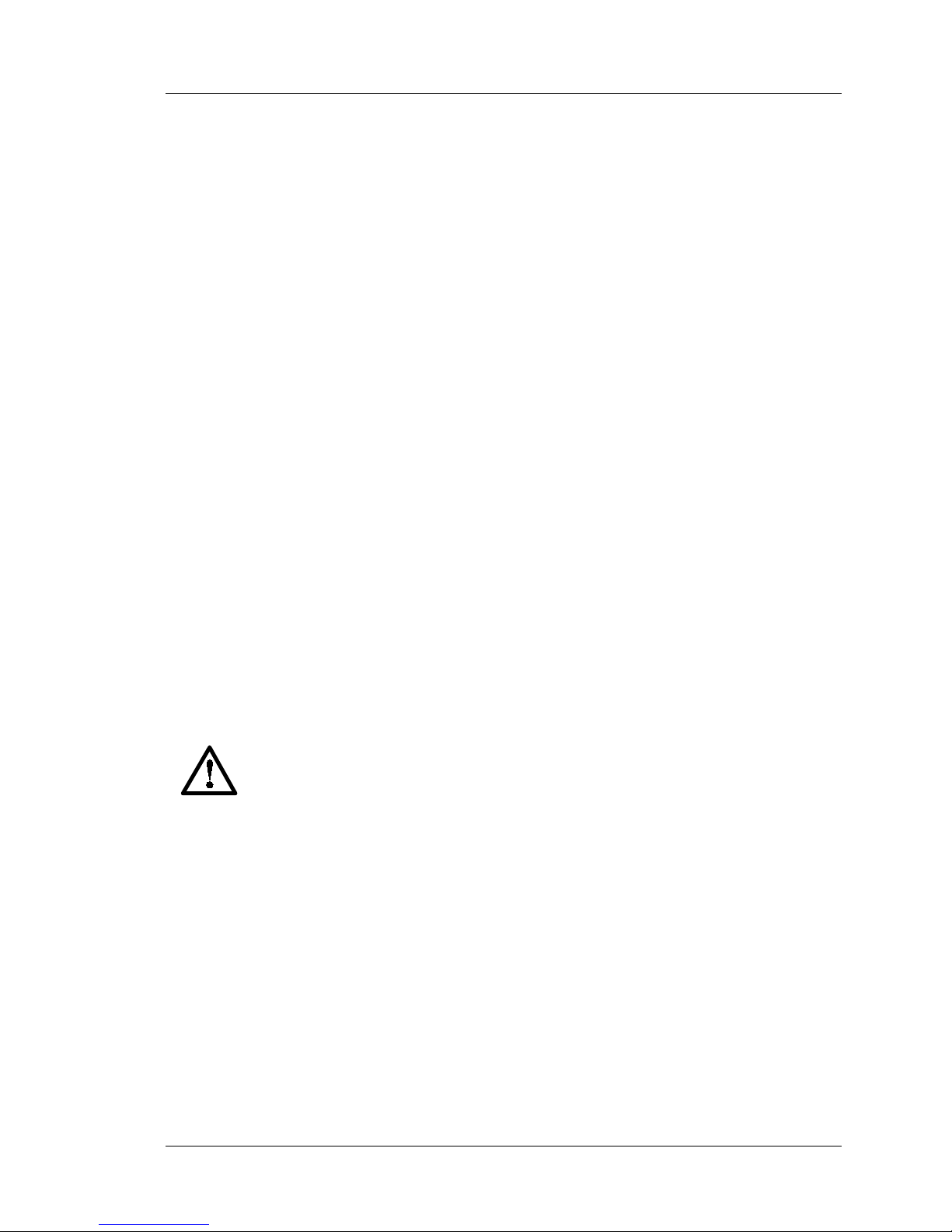
NOTICE
SpectraLink Corporation has prepared this document for use by SpectraLink personnel and clients. The
drawings and specifications contained herein are the property of SpectraLink and shall be neither
reproduced in whole or in part without the prior written approval of SpectraLink, nor be implied to grant
any license to make, use, or sell equipment manufactured in accordance herewith.
SpectraLink reserves the right to make changes in specifications and other information contained in this
document without prior notice, and the reader should in all cases consult SpectraLink to determine whether
any such changes have been made.
The terms and conditions governing the sale of SpectraLink hardware products and the licensing of
SpectraLink software consist solely of those set forth in the written contracts between SpectraLink and its
customers. No representation or other affirmation of fact contained in this document including but not
limited to statements regarding capacity, response-time performance, suitability for use, or performance of
products described herein shall be deemed to be a warranty by SpectraLink for any purpose, or give rise to
any liability of SpectraLink whatsoever.
In no event shall SpectraLink be liable for any incidental, indirect, special, or consequential damages
whatsoever (including but not limited to lost profits) arising out of or related to this document, or the
information contained in it, even if Sp ectraLink has been advised, knew, or sho ul d have known of the
possibility of such damages.
Trademark Information
SpectraLink
LinkPlus
Link Wireless Telepho ne System
NetLink Telephony Gateway
NetLink Wireless Telephone
NetLink SVP Server
SpectraLink Voice Priority
ccLink Wireless Telephone System
are trademarks and registered trademarks of SpectraLink Corporation.
All other trademarks used herein are the property of their respective owners.
Installing the Outdoor Base Station
Link Wireless Telephone System
© 2002 SpectraLink Corporation.
All Rights Reserved
Printed in the United States of America
SpectraLink Corporation
5755 Central Avenue
Boulder, CO 80301
Within the United States, dial
303.440.5330 or toll free
800.676.5465
Outside the U.S., dial
+1.303.440.5330
www.spectralink.com
Part Number: 72-0050-01-B.doc Page 2
Page 3
SpectraLink Corporation Installing the Outdoor Base Station
Link WTS
1. About This Document
The Outdoor Base Station is designed to withstand environmental hazards such as rain
and excessive heat and cold. The outdoor enclosure is mounted into position and the Base
Station is then installed within it. The entire unit is then referred to as an Outdoor Base
Station.
This document covers the installation of the Outdoor Base Station in a variety of
situations. It supplements the installation documentation for the Link Wireless Telephone
System (Link WTS) using either the Link 3000 MCU (see Link WTS – Link 3000:
Installation) or the Link 150 MCU (see Link WTS – Link 150: Installation). Refer to
these documents for SpectraLink notes and disclaimers, UL information, FCC
information, and Industry Canada (IC) notice.
1.1 Contacting SpectraLink
SpectraLink wants every customer to have a successful installation. Please refer
questions to our Customer Support Hotline at (800) 775-5330. The Hotline is open
Monday through Friday, 7:00 AM to 6:00 PM Mountain Time.
2. Installing Flush Against a Wall or Hard
Ceiling
Note concerning shielded cable:
Items provided: Outdoor enclosure, Base Station
Items Needed: 4 anchor bolts (length and type depends on wall or ceiling material
1. Mark and drill four holes into the wall or ceiling, using the mounting flanges of
2. Mount outdoor enclosure to wall or ceiling using anchor bolts. The outdoor
SpectraLink recommends the use of shielded cable for all external signal
connections in order to maintain FCC Part 15 emissions requirements.
When installing Base Stations outside or in buildings other than the one
containing the System Controller, take the following precaution:
If wiring for a Base Station exits a building—whether to reach an outdoor
Base Station location or to reach a Base Station in another building—the
wiring must be protected at both ends by a Quick Clip Fuse from Illinois
Tool Works, Linx Division, model number SCP-2X2. The Quick Clip
Fuse replaces the bridging clips on the 66 blocks for all four connections
to the non-internal Base Station.
Base Station is being mounted to)
the outdoor enclosure as a guide.
enclosure can be mounted with the compression fitting in any direction.
Part Number: 72-0050-01-B.doc Page 3
Page 4

SpectraLink Corporation Installing the Outdoor Base Station
Link WTS
3. Slide the Base Station cable through the compression fitting and tighten fitting.
Compression
fitting
4. Crimp an RJ45 onto the Base Station cable using the same wiring guide as the
indoor Base Station.
5. Plug the RJ45 into the RJ48C connector.
RJ48C
connector
Mounting
hole
Part Number: 72-0050-01-B.doc Page 4
Page 5
SpectraLink Corporation Installing the Outdoor Base Station
Link WTS
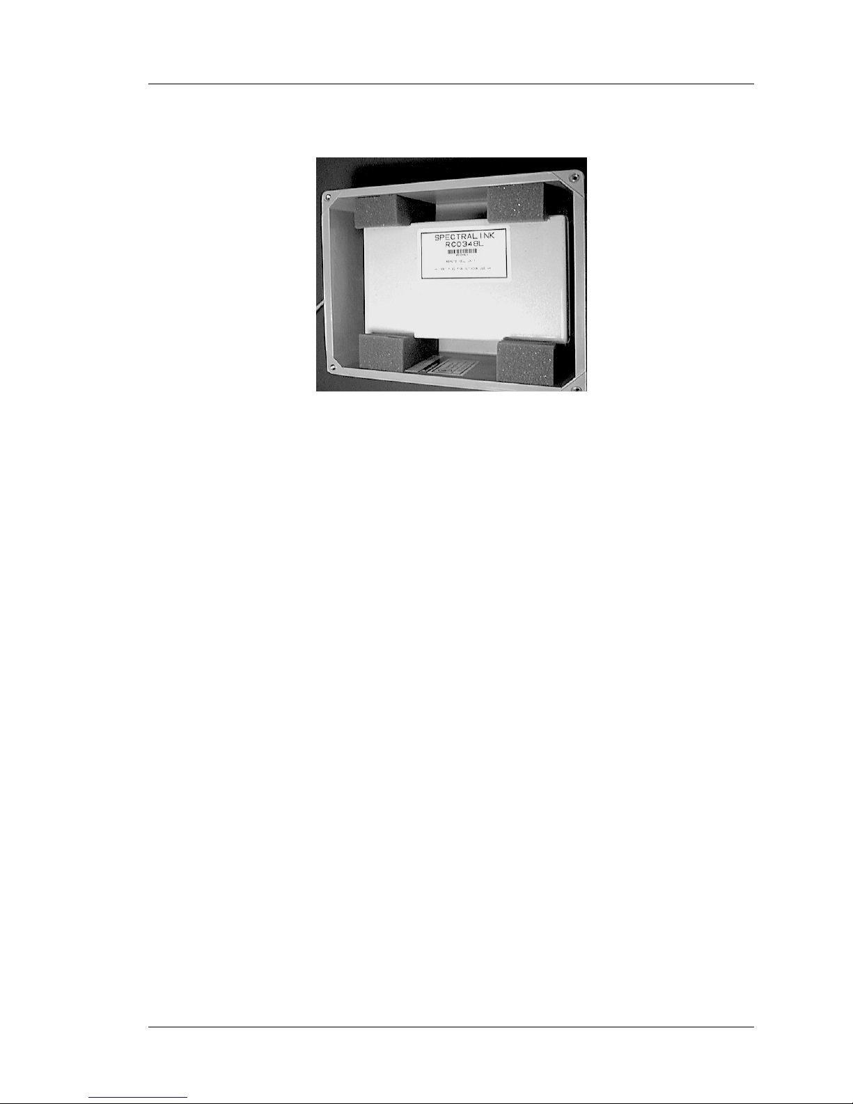
6. Place the Base Station into the enclosure with the side of the Base Station with the
mounting hole facing the wall or ceiling. The Base Station should fit tightly into
the foam blocks.
7. Screw the outdoor enclosure lid back onto the enclosure.
Part Number: 72-0050-01-B.doc Page 5
Page 6

SpectraLink Corporation Installing the Outdoor Base Station
Link WTS
3. Installing on an I-Beam
Items provided : Outdoor enclosure, Base Station
Items needed : 4 - “Caddy” or “B-Line” 3/8” Beam Clamps
4 - ½” ¼” x 20 bolts
4 - 2” ¼” x 20 bolts
4 - ¼” x 20 nuts
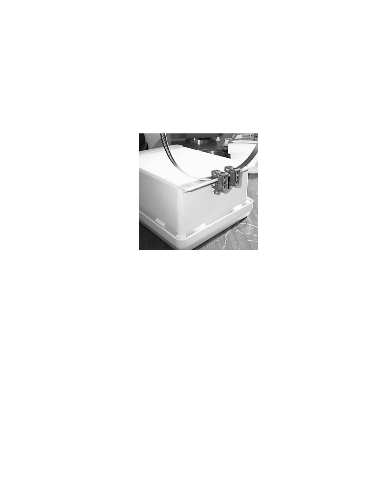
1. Attach a beam clamp to the center of the top and bottom flanges on the outdoor
enclosure.
2. Attach a second beam clamp to each of the beam clamps on the enclosure using a
½” ¼” x 20 bolt and a nut. (See Picture Below)
3. Attach the outdoor enclosure to I-Beam using the beam clamps attached in step 2.
See figures in Section 2 for pictorial data for the remaining steps:
4. Slide the Base Station cable through the compression fitting and tighten the
fitting.
5. Crimp an RJ45 onto the Base Station cable using the same wiring guide as the
indoor Base Station.
6. Plug the RJ45 into the RJ48C connector.
7. Place the Base Station into the enclosure with the side of the Base Station with the
mounting hole facing the I-beam. The Base Station should fit tightly between the
foam.
8. Screw the outdoor enclosure lid back onto the enclosure.
Part Number: 72-0050-01-B.doc Page 6
Page 7
SpectraLink Corporation Installing the Outdoor Base Station
Link WTS
4. Installing on a Light Pole or Electrical
Pole
Items provided: Outdoor enclosure, Base Station
Items needed: 4 - “Caddy” or “B-L ine” 3/8” Beam Clamps
2 - EOG 100 or Equivalent Band Clamps
1. Attach one band to the top flange of the outdoor enclosure using 2 beam clamps
(see the figure below).
2. Attach the second band to the bottom flange of the enclosure using the remaining
two beam clamps.
3. Wrap the band clamps around the pole and tighten using the screw on the band
clamps.
See figures in Section 2 for pictorial data for the remaining steps:
4. Slide the Base Station cable through the compression fitting and tighten the
fitting.
5. Crimp an RJ45 onto the Base Station cable using the same wiring guide as the
indoor Base Station.
6. Plug the RJ45 into the RJ48C connector.
7. Place the Base Station into the enclosure with the side of the Base Station with the
mounting hole facing the pole. The Base Station should fit tightly between the
foam.
8. Screw the outdoor enclosure lid back onto the enclosure.
Part Number: 72-0050-01-B.doc Page 7
 Loading...