

Page 1

Maintenance and Diagnostics
Link Wireless Telephone System
Link 3000 MCU
Part Number: 72-0059-04
Issue E
Page 2

SpectraLink Corporation Maintenance and Diagnostics
Link WTS – Link 3000 MCU
NOTICE
SpectraLink Corporation has prepared this document for use by SpectraLink personnel and clients. The
drawings and specifications contained herein are the property of SpectraLink and shall be neither
reproduced in whole or in part without the prior written approval of SpectraLink, nor be implied to grant
any license to make, use, or sell equipment manufactured in accordance herewith.
SpectraLink reserves the right to make changes in specifications and other information contained in this
document without prior notice, and the reader should in all cases consult SpectraLink to determine whether
any such changes have been made.
The terms and conditions governing the sale of SpectraLink hardware products and the licensing of
SpectraLink software consist solely of those set forth in the written contracts between SpectraLink and its
customers. No representation or other affirmation of fact contained in this document including but not
limited to statements regarding capacity, response-time performance, suitability for use, or performance of
products described herein shall be deemed to be a warranty by SpectraLink for any purpose, or give rise to
any liability of SpectraLink whatsoever.
In no event shall SpectraLink be liable for any incidental, indirect, special, or consequential damages
whatsoever (including but not limited to lost profits) arising out of or related to this document, or the
information contained in it, even if SpectraLink has been advised, knew, or should have known of the
possibility of such damages.
Trademark Information
SpectraLink
LinkPlus
Link Wireless Telephone System
NetLink Telephony Gateway
NetLink Wireless Telephone
NetLink SVP Server
SpectraLink Voice Priority
ccLink Wireless Telephone System
are trademarks and registered trademarks of SpectraLink Corporation.
All other trademarks used herein are the property of their respective owners.
Maintenance and Diagnostics
Link WTS
Link 3000 MCU
System Documentation
© 2002 SpectraLink Corporation.
All Rights Reserved
Printed in the United States of America
SpectraLink Corporation
5755 Central Avenue
Boulder, CO 80301
Within the United States, dial
303.440.5330 or toll free
800.676.5465
Outside the U.S., dial
+1.303.440.5330
www.spectralink.com
Part Number: 72-0059-04-E.doc Page 2
Page 3

SpectraLink Corporation Maintenance and Diagnostics
Link WTS – Link 3000 MCU
Note concerning the Master Control Unit:
This equipment has been tested and found to comply with the limits for a Class A digital device, pursuant
to Part 15 of the FCC Rules. These limits are designed to provide reasonable protection against harmful
interference when the equipment is operated in a commercial environment. This equipment generates, uses,
and can radiate radio frequency energy and, if not installed and used in accordance with the instruction
manual, may cause harmful interference to radio communications. Operation of this equipment in a
residential area is likely to cause harmful interference in which case the user will be required to correct the
interference at his own expense.
Note concerning shielded cable:
SpectraLink recommends the use of shielded cable for all external signal connections in order to maintain
FCC Part 15 emissions requirements.
Note concerning the Wireless Telephone and Base Stations:
This device complies with Part 15 of the FCC Rules. Operation is subject to the following two conditions:
(1) This device may not cause harmful interference, and (2) this device must accept any interference
received, including interference that may cause undesired operation.
WARNING Changes or modifications to this equipment not approved by SpectraLink Corporation may
cause this equipment to not comply with part 15 of the FCC rules and void the user’s authority to operate
this equipment.
WARNING SpectraLink products contain no user-serviceable parts inside. Refer servicing to qualified
service personnel.
Part Number: 72-0059-04-E.doc Page 3
Page 4

SpectraLink Corporation Maintenance and Diagnostics
Link WTS – Link 3000 MCU
UL Information
This symbol on the nameplate means the product is listed by Underwriter’s
Laboratories, Inc. It is designed and manufactured to meet rigid U.L. safety
The following are statements required for UL certification, related to safety procedures
that must be adhered to during installation.
Follow these general precautions while installing telephone equipment:
Never install telephone wiring during a lightning storm.
Never install telephone jacks in wet locations unless the jack is specifically designed
for wet locations.
Never touch uninsulated telephone wires or terminals unless the telephone line has
been disconnected at the network interface.
standards against X-radiation, fire, casualty, and electrical hazards.
Use caution when installing or modifying telephone lines.
When installing Base Stations outside or in buildings other than the one containing the
System Controller, take the following precaution:
If wiring for a Base Station exits a building—whether to reach an outdoor Base Station
location or to reach a Base Station in another building—the wiring must be protected at
both ends by a Quick Clip Fuse from Illinois Tool Works, Linx Division, model number
SCP-2X2. The Quick Clip Fuse replaces the bridging clips on the 66 blocks for all four
connections to the non-internal Base Station.
Part Number: 72-0059-04-E.doc Page 4
Page 5

SpectraLink Corporation Maintenance and Diagnostics
Link WTS – Link 3000 MCU
FCC Information
The Master Control Unit Complies with Part 68, FCC Rules
FCC Registration Numbers:
Link 3000: IYGUSA-7385Q-PX-T
Ringer Equivalence:
Link 3000: 0.3B
SpectraLink Corporation
Link 3000
Made in the USA
This equipment complies with Part 68 of the FCC Rules. On the back of this equipment is a label that
contains, among other information, the FCC Registration Number and Ringer Equivalence Number (REN)
for this equipment. If requested, this information must be given to the telephone company.
This equipment uses RJ-21 connectors.
The REN is useful to determine the quantity of devices you may connect to your telephone line and still
have all of those devices ring when your number is called. In most, but not all, areas, the sum of the RENs
of all devices connected to one line should not exceed five (5.0). To be certain of the number of devices
you may connect to your line, as determined by the REN, you should contact your local telephone company
to determine the maximum REN for your calling area.
If your telephone equipment causes harm to the telephone network, the telephone service may discontinue
your service temporarily. If possible, they will notify you in advance. But if advance notice isn’t practical,
you will be notified as soon as possible. You will be informed of your right to file a complaint with the
FCC.
Your telephone company may make changes in its facilities, equipment, operations or procedures that
could affect the proper functioning of your equipment. If they do, you will be notified in advance to give
you an opportunity to maintain uninterrupted telephone service.
If you experience trouble with this telephone equipment, please contact SpectraLink Corporation for
information on obtaining service or repairs.
SpectraLink Corporation
5755 Central Avenue
Boulder, CO 80301
303-440-5330
The telephone company may ask that you disconnect this equipment from the network until the problem
has been corrected or until you are sure that the equipment is not malfunctioning. There are no user
serviceable parts in this equipment.
This equipment may not be used on coin service provided by the telephone company. Connection to party
lines is subject to state tariffs.
Part Number: 72-0059-04-E.doc Page 5
Page 6

SpectraLink Corporation Maintenance and Diagnostics
Link WTS – Link 3000 MCU
Industry Canada (IC) Notice
Notice:
The Industry Canada (IC) label identifies certified equipment. This certification means that the
equipment meets telecommunications network protective, operational, and safety requirements as
prescribed in the appropriate Terminal Equipment Technical Requirements document(s). The
department does not guarantee the equipment will operate to the user’s satisfaction.
Before installing this equipment, users should ensure that it is permissible to be connected to the
facilities of the local telecommunications company. The equipment must also be installed using an
acceptable method of connection. The customer should be aware that compliance with the above
conditions may not prevent degradation of service in some situations.
Repairs to certified equipment should be coordinated by a representative designated by the
supplier. Any repairs or alterations made by a user to this equipment, or equipment malfunctions,
may give the telecommunications company cause to request the user to disconnect the equipment.
Users should ensure for their own protection that the electrical ground connections of the power
utility, telephone lines and internal metallic water pipe system, if present, are connected together.
This precaution may be particularly important in rural areas.
Caution: Users should not attempt to make such connections themselves, but should contact the
appropriate electric inspection authority, or electrician, as appropriate.
Notice: The Ringer Equivalence Number (REN) assigned to each terminal device provides as
indication of the maximum number of terminals allowed to be connected to a telephone interface.
The termination of an interface may consist of any combination of devices.
REN 0.3B
Approval Numbers:
Link 3000: 2128-9508 A
Warranty and Repair Service Center:
SpectraLink Corporation
5755 Central Avenue
Boulder, CO 80301
303-440-5330
DOC Spread Spectrum certification
Base Station Cert. No. 2128-K1373
Wireless Telephone Cert. No. 2128-K1374
Part Number: 72-0059-04-E.doc Page 6
Page 7

SpectraLink Corporation Maintenance and Diagnostics
Link WTS – Link 3000 MCU
Table of Contents
1. ABOUT THIS DOCUMENT 9
1.1 Contacting SpectraLink 9
1.2 Icons Used in this Document 9
1.3 Troubleshooting Overview 9
2. SYSTEM MAINTENANCE 11
2.1 Replace an Interface Module (Hot Swap) 11
2.2 Add a Wireless Telephone 12
2.3 Replace a Wireless Telephone 12
2.4 Delete a Wireless Telephone 13
2.5 Add a Base Station 14
2.6 Replace a Base Station 15
2.7 Delete a Base Station 15
2.8 Add a Shelf 16
2.9 Delete a Shelf 16
3. WIRELESS TELEPHONE PROBLEMS 17
3.1 Using the Link Wireless Telephones 17
3.2 No Extension/Wrong Extension Displayed 17
3.3 “No Svc” Displayed 18
3.4 No Dialtone / No Audio 18
3.5 No Handoff 19
3.6 Calls Ring on the Wrong Wireless Telephone 19
3.7 Multiple Wireless Telephones Not Working 19
4. BASE STATION PROBLEMS 21
4.1 Multiple Base Stations Not Working 21
4.2 Base Station LED not lit 21
4.3 Base Station LED Flashing Red and Green 22
4.4 Base Station Disabled 22
4.5 Base Station Will Not Download 24
4.6 Base Station LED Flashing Red 24
4.7 Base Station LED Solid Red or Yellow 24
4.8 Base Station LED Flashing Red, Yellow, Green 25
Part Number: 72-0059-04-E.doc Page 7
Page 8

SpectraLink Corporation Maintenance and Diagnostics
Link WTS – Link 3000 MCU
5. TROUBLESHOOTING DURING START-UP PHASE 26
5.1 Boot ROM LEDs 26
5.2 Boot ROM Alarms 27
5.3 Downloads 27
5.4 Configuration Changes 27
6. TROUBLESHOOTING CARD ALARMS 28
6.1 System and Shelf Controller Card Status Indicators 28
6.2 Interface Module Status LEDs 30
6.3 Reading the Status LEDs 31
7. LED AND ALARM TROUBLESHOOTING TABLES 32
7.1 System Controller Card Alarm Matrix 32
7.2 System Controller Card Troubleshooting Matrix 33
7.3 Shelf Controller Card Alarms 38
7.4 Shelf Controller Card Troubleshooting Matrix 39
7.5 Interface Module Alarm Matrix 41
7.6 Interface Module Troubleshooting Matrix 43
7.7 T1 Alarms 46
8. TERMS AND ACRONYMS 48
Part Number: 72-0059-04-E.doc Page 8
Page 9

SpectraLink Corporation Maintenance and Diagnostics
Link WTS – Link 3000 MCU
1. About This Document
This document describes the procedures for troubleshooting, maintaining, and expanding
the Link Wireless Telephone System (Link WTS).
Additional information about the Link WTS can be found in the following SpectraLink
user manuals:
Installation - Part Number 72-0059-01
Operator's Console - Part Number 72-0059-02
LinkPlus Interface Guide - Part Number 72-0171-xx as appropriate for the PBX.
Facility Preparation - Part Number 72-0059-05
1.1 Contacting SpectraLink
SpectraLink wants every customer to have a successful installation. Please refer questions
to our Customer Support Hotline at (800) 775-5330. The Hotline is open Monday
through Friday, 7:00 AM to 6:00 PM Mountain Time.
1.2 Icons Used in this Document
This manual uses the following icons and conventions.
Caution! Follow these instructions carefully to avoid danger.
Note these instructions carefully.
NORM
This typeface indicates a key, label, or button.
1.3 Troubleshooting Overview
The Link WTS software constantly monitors system components for problems. If a
problem is detected, the system will flag the problem with an alarm. Alarms are displayed
in two places:
Operator's Console - the Chk3000 program allows the administrator or technician to
display details about each system component. If the component is in an alarm state,
details about the alarm will display on the appropriate screen. See the Link WTS –
Link 3000 MCU: Operator's Console manual (72-0059-02) for more information.
Part Number: 72-0059-04-E.doc Page 9
Page 10

SpectraLink Corporation Maintenance and Diagnostics
Link WTS – Link 3000 MCU
LEDs - The front panels of all system cards (System Controller, Shelf Controller, and
Interface Modules) have six LEDs: one red (labeled ALARM), and five green
(labeled 1-5) to indicate status, including alarm conditions. LED sequences,
descriptions, and recommended procedures are provided in the section on
Troubleshooting Alarm Codes for each type of card.
Part Number: 72-0059-04-E.doc Page 10
Page 11

SpectraLink Corporation Maintenance and Diagnostics
Link WTS – Link 3000 MCU
2. System Maintenance
This section explains some common maintenance procedures.
2.1 Replace an Interface Module (Hot Swap)
Interface Modules can be removed and replaced without shutting the system down.
Interface Modules must be replaced with the same type of card.
To perform a “hot swap” of an Interface Module:
1. From the Operator’s Console, select F2, Port Card Status. Display the port card
to be swapped, so you can monitor its status during the process.
2. On the card to be replaced, move the Normal/Disable switch to the Disable
position. This locks the card and disables the Base Stations to prevent new calls
from starting, but does not drop active calls. Existing calls are allowed to
complete before the card is locked.
3. When the alarm light stops blinking and turns solid red, the card is idle. Verify
this on the Operator’s Console, all lines and Base Stations should show no
activity. If you unplug the card before it is idle, the system may alarm.
4. At the Operator’s Console, press ESC. This stops the Operator’s Console from
trying to monitor the card you are about to remove.
5. Unplug the 25 pair cable from the card.
6. Unscrew the card from the shelf and slide it out.
7. Slide the replacement Interface Module into the slot, until the card clicks into
place. Tighten the screws at the top and bottom of the card to secure it.
8. Connect the 25 pair cable to the card.
9. When the heartbeat LED sequence displays on the Interface Module (LED 1
flashes 1/3 of the time), select
the new card. It should be
F2 on the Operator’s Console to verify the status of
Running.
Part Number: 72-0059-04-E.doc Page 11
Page 12

SpectraLink Corporation Maintenance and Diagnostics
Link WTS – Link 3000 MCU
2.2 Add a Wireless Telephone
Before adding a new Wireless Telephone, you must have a port location on the
demarcation block on the switch and a port location on the Link 3000 MCU Interface
Module. If no ports are available on the Link 3000 MCU, you must install another
Interface Module in the shelf. See Link WTS – Link 3000 MCU: Installation.
1. Connect the host telephone system port to the Link 3000 MCU Interface Module
port assigned to the new Wireless Telephone.
2. On the Operator’s Console, select F4, Port Card Configuration Display and
Administration.
3. Using the arrow keys or mouse, position the cursor on the port location to be
configured, and press Enter.
4. When the menu displays, scroll down to Edit Line, and press Enter.
5. At the pop-up menu, type the information for the Wireless Telephone.
Serial Number – the factory assigned serial number for this telephone, located
inside the battery compartment under the battery. Double check this number when
it is entered. If the Serial Number is entered incorrectly the telephone will not
function and will appear to be defective.
Note - (optional) user name or any other information. Do not enter double quotes
(“) in this field, an error message will display.
Extension/SPID - extension number or SPID. Must be numeric.
6. When information is correctly entered, select SAVE to save it.
7. To program the Wireless Telephone to display the correct extension number, hold
down the FCN key until Volume Level displays. Press the # > key (NEXT) until
EXTENSION displays on the Wireless Telephone. Press 0, then enter the correct
extension number. Press END when finished.
8. When the Wireless Telephone is turned ON, the extension will be displayed. Test
the new Wireless Telephones by placing a call to each one to verify that the
correct telephone rings.
2.3 Replace a Wireless Telephone
Use this procedure to replace a Wireless Telephone with a new Wireless Telephone.
1. On the Operator’s Console, select F4,
Administration. Use the Search function to locate the Wireless Telephone to be
replaced, searching for the extension or the serial number.
2. Highlight the port location of the telephone and select
Port Card Configuration Display and
Edit Line.
3. When the pop-up screen displays, replace the serial number of the old telephone
with the serial number of the new telephone.
4. Select SAVE to save the change.
Part Number: 72-0059-04-E.doc Page 12
Page 13

SpectraLink Corporation Maintenance and Diagnostics
Link WTS – Link 3000 MCU
2.4 Delete a Wireless Telephone
Use this procedure to completely remove a Wireless Telephone from the system, without
replacing the telephone with another.
1. On the Operator’s Console, select F4, Port Card Configuration Display and
Administration.
2. Using the arrow keys or mouse, position the cursor on the port location of the
telephone to be deleted, and press Enter.
3. When the menu displays, scroll down to Delete Line, and press Enter.
4. Scroll to DELETE and press Enter.
5. If you do not plan to re-use the port on the Link WTS, remove the cabling for this
telephone between the host telephone system and the Link WTS’s demarc block.
Part Number: 72-0059-04-E.doc Page 13
Page 14

SpectraLink Corporation Maintenance and Diagnostics
Link WTS – Link 3000 MCU
2.5 Add a Base Station
Before adding a new Base Station you should have a port location for the new equipment.
If no ports are available on the Link 3000 MCU, you must install another Interface
Module in the shelf. See Link WTS – Link 3000 MCU: Installation.
1. Install the new Base Station. See Link WTS – Link 3000 MCU: Installation.
2. On the Operator’s Console, select F4, Port Card Configuration Display and
Administration
3. Using the arrow keys or mouse, position the cursor on the port location to be
configured, and press Enter.
.
4. When the menu displays, scroll down to
Edit RCU (Base Station), and press
Enter.
5. At the pop-up menu, type the information for each Base Station.
Offset - Offset IDs manage the division of the frequency (spectrum) among the
Base Stations. To prevent interference, neighboring Base Stations require
different offset values. Each Base Station is assigned a unique two-digit offset.
Press Right Arrow to see a menu of choices.
For half-hop systems with up to 25 Base Stations, or whole-hop systems with
up to 50 Base Stations, number the Base Stations in order 1-25 or 1-50.
If the system has more Base Stations, the offset IDs must be reused. Consult
the map that was generated during system installation. Assign unique offsets
such that adjacent or nearby Base Stations do not share the same offset. When
selecting offset assignments, keep in mind through-floor penetration and the
Base Station’s proximity to windows.
Offset usage is summarized on the Show RCU Offset Reuse function from
F2 - Port Card State. This report shows how many times each Offset has
been used.
Isolated? - If this Base Station is isolated from all other Base Stations, enter Y.
An isolated Base Station is one that is located physically apart from other Base
Stations, therefore will never be heard during a Listen/Verify diagnostic.
Designating a Base Station as Isolated will disable the Listen Verify alarm for that
Base Station and avoid generating spurious alarms.
Note - (optional) type a short description of where the Base Station was installed
(a room or floor number, for example). Up to 30 characters. Do not enter double
quotes (“) in this field, an error message will display.
6. When information is correctly entered, select SAVE to save it.
Part Number: 72-0059-04-E.doc Page 14
Page 15

SpectraLink Corporation Maintenance and Diagnostics
Link WTS – Link 3000 MCU
2.6 Replace a Base Station
To replace a Base Station, unplug the existing Base Station and plug in the new Base
Station.
The LED will blink red and green as the system software downloads to the
Base Station and the Base Station is tested.
When the LED blinks amber, the system is ready for operation.
When the LED blinks green, a Wireless Telephone has established a radio link
with that Base Station.
If the LED turns solid red, blinks red, or continues to blink red and green,
refer to Base Station Problems.
2.7 Delete a Base Station
Use this procedure to completely remove a Base Station without replacing it with a new
one.
1. On the Operator’s Console, select F4, Port Card Configuration Display and
Administration.
2. Using the arrow keys or mouse, position the cursor on the port location of the
Base Station to be deleted, and press Enter.
3. When the menu displays, scroll down to Delete RCU, and press Enter.
4. Scroll to DELETE and press Enter.
5. If you do not intend to move the Base Station to a new location, disconnect the
cabling for this Base Station from the demarc block.
Part Number: 72-0059-04-E.doc Page 15
Page 16

SpectraLink Corporation Maintenance and Diagnostics
Link WTS – Link 3000 MCU
2.8 Add a Shelf
If the existing shelves in the MCU are not large enough to hold the required Interface
Modules, you must add a shelf to the system. The system can support 19 Expansion
Shelves.
1. Install the shelf. See Link WTS – Link 3000 MCU: Installation.
2. If you moved Interface Modules from one shelf into the new shelf, use the Move
Port Card function to modify the existing Interface Module configuration to
reflect the change.
3. Register the new Wireless Telephones and/or Base Stations on the new shelf. See
Add A Wireless Telephone and Add A Base Station.
2.9 Delete a Shelf
If you move or reconfigure your system, you may need to completely delete a shelf.
1. On the Operator’s Console, select F4, Port Card Configuration Display and
Administration.
2. If you are completely removing the Wireless Telephones and Base Stations from
this system, delete the Base Stations and Wireless Telephone by deleting each
Interface Module on the shelf using the Delete Port Card (Interface Module)
option.
3. If you are moving the Wireless Telephones and Base Stations from this shelf to
another, use the Move Port Card (Interface Module) option to designate the new
shelf location of the Interface Module. Note that you cannot move an Interface
Module to a slot which already contains configuration information. Also, the
Interface Module must be physically moved to the new slot and connected with a
cable in order for the module to become operational.
4. When all Interface Modules have been deleted or moved from the shelf, select F1
– Supervisor State Display. Select the Delete Cabinet (shelf) option to delete
the shelf.
5. After the shelf is deleted from the system you can physically remove it and its
cabling.
Part Number: 72-0059-04-E.doc Page 16
Page 17

SpectraLink Corporation Maintenance and Diagnostics
Link WTS – Link 3000 MCU
3. Wireless Telephone Problems
3.1 Using the Link Wireless Telephones
The Link WTS is an in-building wireless communication system that allows hand-held
Wireless Telephones to communicate using the existing telephone system. Calls are sent
to and received by the Wireless Telephones via small radio transceivers called Base
Stations, located throughout the building or campus. When using and troubleshooting the
Wireless Telephones, consider the following concepts.
Call hand off – as the user moves through the facility, your conversation will be
“handed off” from one Base Station to another.
In range/Out of range – service will be disrupted if a user moves outside the
transmission area of the Link WTS. Service is restored if the user moves back within
range of a Base Station. If a call drops because a user moves out of range, the
Wireless Telephone will recover the call if the user moves back into range within a
few seconds.
Capacity – in areas of heavy use, the call capacity of a particular Base Station may
be filled. If this happens, the user can wait until another user terminates a call, or
move within range of another Base Station and try the call again. If a user is on a call
and moves into an area where capacity is full, it is the same as moving out of range of
a Base Station.
Transmission Obstructions – a thorough site survey was done prior to installation
to determine the best location for Base Stations for optimum transmission coverage.
However, small pockets of obstruction may still be present, or obstructions may be
introduced into the facility after system installation. This loss of service can be
restored by moving out of the obstructed area. Base Stations can also be added to
overcome obstructions.
3.2 No Extension/Wrong Extension Displayed
1. Hold down the FCN key until Volume Level display.
2. Press the # key twice until the display reads “Extension.”
3. Press
4. Press END when finished.
0, then enter the correct extension number.
Part Number: 72-0059-04-E.doc Page 17
Page 18

SpectraLink Corporation Maintenance and Diagnostics
Link WTS – Link 3000 MCU
3.3 “No Svc” Displayed
The Wireless Telephone is either not registered, out of range, or can’t pick up a signal
from a Base Station.
1. Visually check to see if the telephone is within range of a Base Station where
other telephones are working.
2. From the Operator’s Console, search for the telephone’s serial number or
extension number to be sure it is properly registered.
3. If other telephones in the area are also not working, see Multiple Wireless
Telephones Not Working below.
3.4 No Dialtone / No Audio
If the Wireless Telephone has no dialtone, or if the user is unable to hear the other party’s
voice or heard echo or dead air.
1. Be sure the Wireless Telephone is powered on.
2. Be sure the No Svc icon turns off a few seconds after the Wireless Telephone is
powered on.
3. Swap the Battery Pack with a Battery Packfrom a functional Wireless Telephone.
If this corrects the problem, charge the Battery Pack.
4. Turn the Wireless Telephone off then on again, then test again for dial tone and
voice quality.
5. Move through several Base Station areas to be sure the Wireless Telephone is
within range of an operating Base Station.
6. Check for alarms on the System Controller, Shelf Controller, or Interface Module
cards (F1, Supervisor State or F2, Port Card State). If the Wireless Telephone
is connected through a digital interface, the system will show an alarm. If the state
is anything but idle, the Wireless Telephone is in alarm. If there are alarms, see
Troubleshooting Alarms section.
7. Check that the system connects when the user goes off-hook. On the Operator’s
Console, from theF2 -
Port Card State screen, view the status of the Line when
the user goes off-hook.
8. Make sure the Wireless Telephone’s Interface Module is connected to a working
phone line. Use a telephone test set to check the line at the demarc block.
9. Check the cabling between the Interface Modules and the demarc block, and
between the demarc block and the telephone system ports. See Link WTS – Link
3000 MCU: Installation for more information.
10. Isolate the Wireless Telephone line on the PBX from the Link 3000 MCU.
Connect a wired telephone to the port to see if the wired telephone operates
properly.
11. Move the Wireless Telephone to a different port location and test again.
Part Number: 72-0059-04-E.doc Page 18
Page 19

SpectraLink Corporation Maintenance and Diagnostics
Link WTS – Link 3000 MCU
3.5 No Handoff
If the user walks between Base Station coverage areas, the conversation is not handed off,
and the call is dropped.
1. Using another Wireless Telephone, confirm that both Base Stations are
operational.
2. Verify that the Wireless Telephone can hand off between other Base Stations.
3. On the Operator’s Console, from the Port Card State screen (F2) check the status
of the Base Stations. It is possible that the Base Stations have four calls (the
maximum) in progress. If the Base Station is handling three or fewer calls and
still drops the call, see Base Station Problems.
3.6 Calls Ring on the Wrong Wireless Telephone
The Wireless Telephone has probably not been registered correctly.
1. From the Operator’s Console, use the Search function to find the telephone’s
serial number and check its port location.
2. Trace the wires from the back of the Interface Module to the host telephone
system to be sure it is actually connected to that port location.
3. If the physical location is different, note the correct port location. From F4 - Port
Card Configuration Display and Administration
, use the Edit Line function to
change the serial number on the correct port. If the port location is already in use
by another Wireless Telephone, you will need to delete the other telephone (using
Delete Line), then change the serial number on that port location to the serial
number of the new telephone.
3.7 Multiple Wireless Telephones Not Working
If several of the Wireless Telephones are not working there may be a problem with the
Interface Module that controls them, or with one or more Base Stations.
1. Check to see that the Wireless Telephones are correctly registered. See Link WTS
– Link 3000 MCU: Operator’s Console for instructions.
2. At the Operator’s Console, use the
Wireless Telephones (searching for serial number, extension, or user name). If
they are all connected to the same Interface Module, there may be a problem with
that Interface Module.
3. Try replacing the Interface Module with a different Module of the same type (see
Replacing Interface Modules.)
Search function to display details about the
4. Check the cabling between the Interface Modules and the demarc block, and
between the demarc block and the telephone system ports. See Link WTS – Link
3000 MCU: Installation for more information.
5. If the problem persists, diagnose the Base Stations.
Part Number: 72-0059-04-E.doc Page 19
Page 20

SpectraLink Corporation Maintenance and Diagnostics
Link WTS – Link 3000 MCU
4. Base Station Problems
The first step in diagnosing Base Station problems is to isolate the problem to the Base
Station. Be sure the problem is not limited to a single Wireless Telephone. When a
problem occurs with a Wireless Telephone, try the same procedure using another
telephone, or several telephones (see Wireless Telephone Problems.)
If all or several Wireless Telephones are affected, try the following troubleshooting
procedures.
If you try the following troubleshooting procedures and the Base Station still does not
work, return the unit to SpectraLink for service.
4.1 Multiple Base Stations Not Working
If several of the Base Stations are not working there may be a problem with the Interface
Module that controls them.
1. At the Operator’s Console, check for alarms on the Supervisor State (F1) and
Port Card State (F2) screens. Cards or components in alarm will have an
exclamation point (!). See Troubleshooting Alarms for more information.
2. Check to see that the Base Stations are correctly registered. See Link WTS – Link
3000 MCU: Operator’s Console for instructions.
3. If all of the Base Stations are connected to the same Interface Module, there may
be a problem with that Interface Module. Try replacing the Interface Module (see
Replacing Interface Modules) and re-testing the Base Stations.
4. Use a voltmeter to check for 48V DC on the Base Station wiring.
4.2 Base Station LED not lit
The Base Station is not receiving power. On the Port Card Status screen (F2) the status
may show Reset.
1. Be sure the RJ-45 connector is plugged into the Base Station.
2. Be sure the MCU is turned on.
3. With a voltmeter, check the 48V DC on the wiring between the MCU and the
Base Station.
Part Number: 72-0059-04-E.doc Page 20
Page 21

SpectraLink Corporation Maintenance and Diagnostics
Link WTS – Link 3000 MCU
4.3 Base Station LED Flashing Red and Green
The LED on the Base Station is designed to flash in specific colors and patterns to reflect
its functioning. At startup the system goes through a “listen” procedure to ensure that the
Base Stations do not interfere with each other. During the “listen” process the LED will
flash red and green for approximately two minutes.
Certain flashing patterns indicate a problem that needs to be addressed:
If the System Controller disables a Base Station because it interferes with another
Base Station, the disabled Base Station’s LED will flash red and green.
If the Base Station is stuck in “download” the LED will flash red and green. In this
case, verify the status of the Base Station at the Operator’s Console. Select F2 -
Interface Module Status.
If status is Disabled, see Base Station Disabled, below.
If status is Download and the DL Time is longer than 1-2 minutes, see Base Station
Will Not Download, below. Also:
Try disconnecting and reconnecting the power from the Base Station. Unplug
the RJ-45 connector on the Base Station then plug it back in again, or remove
the bridging clips from the demarc block and replace them. If necessary, reset
several Base Stations at once by removing the cable from the Interface
Module. Remember, this will also disconnect Lines and drop calls!
Make sure there are no bridge taps (Ys) on the demarc blocks. Remove any
you find.
Use a voltmeter to check the lines for the 48 V dc to be sure there are no
power problems.
4.4 Base Station Disabled
The System Controller will disable a Base Station if it is too close to another Base Station
or if there are communication errors between the Base Station and the System Controller.
Once disabled the Base Station does not handle any calls.
1. On the Port Card Display (F2) check that the status of this Base Station is
Disabled.
2. Before moving Base Stations, check the facility’s floorplan and the latest Listen
Verify diagnostic (F1,
errors and information.
3. To enable this Base Station, disconnect it and relocate it so it is farther from other
Base Stations.
4. Disconnecting and reconnecting the Base Station will automatically activate the
“listen” procedure. Run the Listen Verify Diagnostic (F1, Run Listen Verify) and
review results to be sure the problem is corrected without creating any new
problems.
Check Listen Verify Report or Show Listen Report) for
Part Number: 72-0059-04-E.doc Page 21
Page 22

SpectraLink Corporation Maintenance and Diagnostics
Link WTS – Link 3000 MCU
4.5 Base Station Will Not Download
If a Base Station is stuck in download, the LED may flash red and green or just red; the
status on the Operator’s Console will show Reset or Download; and the Base Station
will be locked up (not handling calls).
1. At the Operator’s Console, check to see that the Base Station is registered, using
F2 - Port Card Display.
2. Check the status of the Base Station. If the status shows Download or Download
Data, the Base Station has locked up during download.
3. To reset the Base Station: From F2, Port Card Display, highlight the Base
Station and press Enter, then select Reset RCU from the menu.
4. If the Base Station still does not download, try disconnecting power from the Base
Station and then reconnecting it (unplug the RJ-45 connector on the Base Station
then plug it back in again, or remove the bridging clips from the demarc block and
then replace them.)
5. On the Port Card Display (F2) screen, select the Base Station in question and
press Enter to show Base Station Detail. This shows continuous update of the
Base Station’s status. The DL Errors field shows the number of Download Errors.
Any number greater than 0 indicates a problem. RCU Link shows current
transmission errors. These errors are generally caused by hardware problems.
Contact SpectraLink Customer Support for assistance.
4.6 Base Station LED Flashing Red
This indicates that the Base Station is not communicating with the MCU.
1. Follow the instructions in Base Station LED Flashing Red and Green.
2. Be sure there are no bridge taps (“Y”s) on the demarc block. Remove any you
find.
3. If the problem persists, follow instructions in Base Station’s LED Solid Red or
Yellow, below.
4.7 Base Station LED Solid Red or Yellow
This indicates a short in the Base Station’s transmit or receive wire pairs, usually within a
pair.
Be sure none of the wires are shorted together. Remove the RJ-45 connector from the
Base Station. Remove the cable between the Interface Module and the demarc block.
Then use an ohmmeter to be sure there is an open circuit between pins on the RJ-45. If
you do not want to remove the cabling from the Interface Module (so you do not interfere
with system operation), remove the bridging clips on the demarc block for that Base
Station, then test with the ohmmeter.
Part Number: 72-0059-04-E.doc Page 22
Page 23

SpectraLink Corporation Maintenance and Diagnostics
Link WTS – Link 3000 MCU
4.8 Base Station LED Flashing Red, Yellow, Green
The Base Station’s microprocessor is faulty. Replace the Base Station and contact
SpectraLink Customer Service.
Part Number: 72-0059-04-E.doc Page 23
Page 24

SpectraLink Corporation Maintenance and Diagnostics
Link WTS – Link 3000 MCU
5. Troubleshooting During Start-Up Phase
This section describes the sequence of the LEDs on all system cards when the system is
first powered on (Boot ROM and Download of software).
5.1 Boot ROM LEDs
When the system is powered on, the normal sequence is for the green LEDs to 'count' up
from 1 to 12 in binary. The following table outlines the sequence.
LEDs Code Description
0 0 Entered boot code
1 1 Done RAM test (check boot code CRC, flash type, factory page CRC,
downloaded CRC in that order)
2 2 Sent recognition character at 115200 (if carrier detected)
1,2 3 Sent recognition character at 57600 (if carrier detected)
3 4 Sent recognition character at 38400 (if carrier detected; send recognition
character at 9600 if carrier detected)
1,3 5 Jumping to downloader code
2,3 6 Entered downloader code
1,2,3 7 Copied to RAM, entered C code (check flash type, sense board slot,
check board type, CRC functional code, start IPC, in that order)
4 8 Checking for a KEEPALIVE message
1,4 9 Sent version to supervisor **
2,4 10 Awaiting download (sending requests if no other download) **
1,2,4 11 Jumping to functional code (functional code then blinks all the LEDs)
** Note: Codes 9 and 10 both blink at 1-second intervals while awaiting a response
Part Number: 72-0059-04-E.doc Page 24
Page 25

SpectraLink Corporation Maintenance and Diagnostics
Link WTS – Link 3000 MCU
5.2 Boot ROM Alarms
During system boot, if alarms are encountered the red LED will be on. The alarm code
will display on the green status LEDs, consisting of one second of blank lights followed
by two LED sequences which each display for one second.
LED 1 LED 2 Description Recommendation
1 1 RAM test failed Replace card.
1 2 Flash Type incorrect Replace card.
1 1,2 Boot code CRC incorrect Contact SpectraLink Customer
Support.
1 3 Factory page CRC incorrect Contact SpectraLink Customer
Support.
1 1,3 Downloader CRC incorrect Contact SpectraLink Customer
Support.
1 2,3 Bad Board Type Contact SpectraLink Customer
Support.
1 1,2,3 Bad Board Slot Contact SpectraLink Customer
Support.
1 4 Bad Functional Code Contact SpectraLink Customer
Support.
2 1 Error starting IPC Replace card.
2 2 Supervisor communications refusal. Interface Module card is not
configured for PBX type.
2 1,2 No keepalives detected. Shelf Controller card is not yet
operating.
2 3 Bad Shelf Number Contact SpectraLink Customer
Support.
1,2 1 Error writing or erasing flash Replace card.
1,2 2 Error downloading FPGA (not used
by Interface Module)
Replace card.
5.3 Downloads
During downloads, either from the serial port or across the IPC, the green LEDs 'count'
up to show progress in the download. Each serial packet or IPC page increments the
count and it wraps to zero after getting to 31.
5.4 Configuration Changes
When changes are made to the configuration (Base Stations or Lines added or changed),
the information is sent from the System Controller to the Shelf Controller and Interface
Modules. Status LED
Part Number: 72-0059-04-E.doc Page 25
5 blinks on each card during the configuration download.
Page 26
SpectraLink Corporation Maintenance and Diagnostics
Link WTS – Link 3000 MCU
6. Troubleshooting Card Alarms
This section contains information about how to read the alarm LEDs on the system cards.
For a complete list and description of alarms, see the Troubleshooting Matrix.
6.1 System and Shelf Controller Card Status Indicators
If the red LED is off but one or more green LEDs are on, the green LEDs indicate status,
as follows:
LED Description
Green 1 Normal Status when on
Green 2 Card Download in progress
Green 3 Reserved for future use
Green 4 Listen Verify in progress
Green 5 Configuration update in progress
When the red LED is lit, it indicates an alarm code is currently shown on the 5 green
LEDs. When indicating Alarms (from top to bottom):
LED Description
Red Alarm is present
Green 1 Low order bit (bit 1) alarm code
Green 2 Bit 2 alarm code
Green 3 Bit 3 alarm code
Green 4 Bit 4 alarm code
Green 5 High order bit (bit 5) alarm code
Part Number: 72-0059-04-E.doc Page 26
Page 27
SpectraLink Corporation Maintenance and Diagnostics
Link WTS – Link 3000 MCU
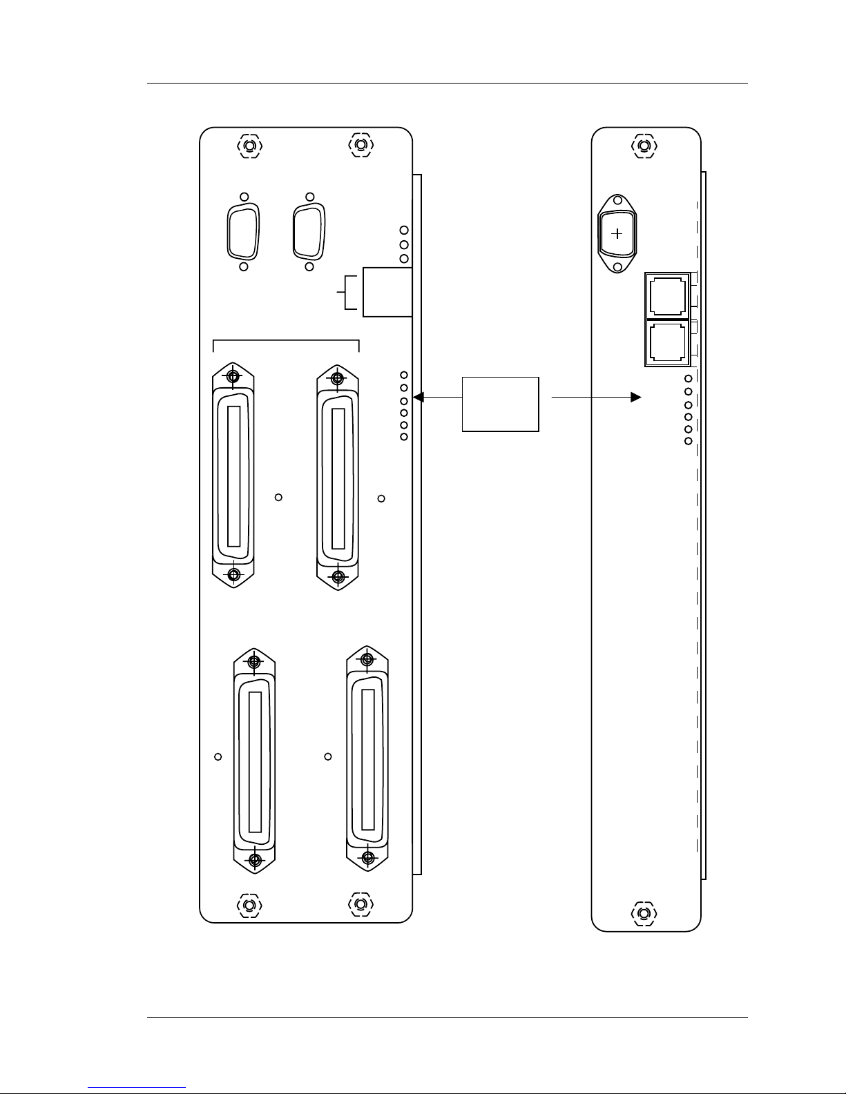
The following diagram shows the System Controller and Shelf Controller cards.
RS-232
A
B
LNKOK
ACT
COL
RS-232
NETWORK
SHELF
17-20 7-11
12-16 2-6
ALARM
(RJ45)
SC/A
(RJ45)
SC/B
1
2
3
4
5
Status
LEDs
ALARM
1
2
3
4
5
System Controller Card Shelf Controller Card
Part Number: 72-0059-04-E.doc Page 27
Page 28

SpectraLink Corporation Maintenance and Diagnostics
Link WTS – Link 3000 MCU
6.2 Interface Module Status LEDs
The Status display on the Interface Module consists of:
LED Description
Red/Alarm Always Off
Green 1 Card is up and running
Green 2 One or more lines in use
Green 3 One or more Base Stations in use
DISABLE
NORMAL
CONN
B
ALARM
CONN
A
1
2
3
4
5
Part Number: 72-0059-04-E.doc Page 28
Interface Module
Page 29

SpectraLink Corporation Maintenance and Diagnostics
Link WTS – Link 3000 MCU
6.3 Reading the Status LEDs
The LEDs cycle in the following sequence:
1. Status
2. Alarm Code (all LEDs off if no alarm exists)
3. Component (all LEDs off if no alarm exists)
The card will iterate through the list of active alarms showing only one of the active
alarms at a time. A System Controller with two alarms, for example, would flash the
following sequence on the LEDs:
Status - alarm code 1 - alarming component 1 - Status - alarm code 2 - alarming
component 2 - Status - alarm code 1 - alarming component 1 etc
Part Number: 72-0059-04-E.doc Page 29
Page 30

Part Number: 72-0059-04-E.doc Page 30
2,3,5
1,3,5
3,5
1,2,5
2,5
1,5
5
1,2,3,4
2,3,4
1,3,4
3,4
1,2,4
2, 4
LEDs
Router Funnel CTLSW IPC Flash
Alarm Code Alarm Components
7.1 System Controller Card Alarm Matrix
This table summarizes the possible alarm codes which can occur for the System Controller card.
7. LED and Alarm Troubleshooting Tables
Link WTS – Link 3000 MCU
SpectraLink Corporation Maintenance and Diagnostics
Download
HW
X X X
Write
X
X
Erase
Read
X
X X X X
RX Full
TX Full
X X X X
X X X
Keepalive
Error
X X X X
X X
Program
Start
X X X X
X X X
No Code
Test
X X X X X
X X X X X X X
1 2 1,2 3 1,3 2,3 1,2,3 4 1,4 2,4 1,2,4 3,4
Config
PC
Config
SCC
UART
1
UART
2
Cards MCU DL
Page 31

Part Number: 72-0059-04-E.doc Page 31
Cards. 2,4 Test - 1,2,4 Often the result of inserting the
Cards -2,4 NoCode - 2,4 No valid code found in the flash
Cards - 2,4 Unknown
SpectraLink Corporation Maintenance and Diagnostics
Cards - 2,4 Start - 1,3,4 This alarm occurs because a card
Cards - 2,4 Keepalive -
7.2 System Controller Card Troubleshooting Matrix
On the Operator’s Console, System Controller alarms display on the Show Cabinet Detail screen for the Primary Shelf (Shelf 1),
accessible from Supervisor State screen (F1). The table is sorted alphabetically by component. LEDs for Component and Alarm are
also shown in the table.
Component -
Second LED
Link WTS – Link 3000 MCU
configured shelf slot.
wrong card into a previously
Insert a card that supports the desired
interface (PBX) type.
Hardware -
2,3,5
did not start running functional
code. This can happen if a card is
Often the result of inserting a newer
Download the code necessary for the
card into an older system.
current revision.
Upgrade the supervisor software to a
memory of the System Controller
card.
card that is alarming.
unplugged while it is starting.
If the card is missing, reinsert the card
or deconfigure it in the Interface
Module configuration window. If the
card is present, look at its alarm LEDs
for clarification of the cause of the
problem.
shelf going to the alarming Interface
Module.
Interface Module and the
supervisor.
Possible incorrect cabling between
the System Controller and a Shelf
Controller. Check the cabling for the
2,3,4
a removed card in the system. Also
caused by a breakdown in IPC
communications between the
the system. If no card is present,
either insert a card or deconfigure it
by deleting the PBX type.
Alarm - First
LED
Often the result of a missing card or
Probable Cause Recommendation Notes
Check to see if a card is present in
Missing card code may be seen in
conjunction with another error such
as Supervisor DL error Bad
Download Image.
in an idle, locked state as this or
other alarms may occur.
Avoid removing a card before it is
Stations by the time the keepalive
timeout occurs will be dropped.
have not handed off to other Base
Any active calls that are on the
missing card's Base Stations and
Can be caused by removing a card
before it has reached its normal
state. Removing a card before it is
an idle, locked state should be
generally avoided at this or other
alarms may occur.
Page 32

Part Number: 72-0059-04-E.doc Page 32
Funnel - 2 Start - 1,3,4 Internal error Contact SpectraLink Customer
Funnel - 2 Program - 3,4 Funnel/router FPGA on System
Funnel - 2 Error -
DownLoad -
Flash - 1,3 Erase - 2,5 Bad flash Replace System Controller card.
Flash - 1,3 Read - 1,2,5 Bad flash Replace System Controller card.
Flash - 1,3 Test - 1,2,4 Bad or wrong flash memory Replace System Controller card.
Flash - 1,3 Write - 3,5 Bad flash Replace System Controller card.
3,4
Control SW-
1,2
Control SW -
1,2
Control SW -
1,2
SpectraLink Corporation Maintenance and Diagnostics
Link WTS – Link 3000 MCU
Component -
Second LED
Support.
Controller will not accept a
download.
Controller will not accept a
download.
Program - 3,4 Control SW FPGA on System
NoCode - 2,4 No valid code to program Control
Alarm - First
LED
SW-FPGA
1,2,3,4
Internal error Contact SpectraLink Customer
NoCode - 2,4 Bad code in flash If the result of a software download to
Test - 1,2,4 FPGAs on System Controller will
not accept download.
Probable Cause Recommendation Notes
Replace System Controller card. IPC Communications will not work
Support.
system, check downloaded code.
Replace System Controller card. Indicates a condition that affects all
Replace System Controller card. The MCU start alarm can be seen
board is probably bad and should be
replaced.
did a download, retry the download. If
a no download was done lately, the
Check supervisor software. If you just
Base Station and the line are on a
in system. Keepalive card alarms
can be seen because of conditions
causing this alarm.
As a result of this error, audio may
be interrupted on calls where the
Base Station and the line are on a
different half-shelf.
different half-shelf.
As a result of this error, audio may
be interrupted on calls where the
with a flash error.
as a result of this problem.
The MCU start alarm can be seen
as a result of this problem.
FPGAs on the System Controller.
(no FPGA will download). MCU
alarm also seen as a result.
Alarm may occur in conjunction
Page 33

Part Number: 72-0059-04-E.doc Page 33
MCU - 1,2,4 TX Full - 1,5 Internal error Contact SpectraLink Customer
MCU - 1,2,4 Read - 1,2,5 Internal erro. Contact SpectraLink Customer
MCU - 1,2,4 Test - 1,2,4 Code downloaded to the System
MCU - 1,2,4 Error -
IPC - 3 RX Full - 5 Supervisor encountered a
IPC - 3 HW - 2,3,5 Cabling problem between the Shelf
IPC - 3 TX Full - 1,5 Supervisor encountered a
IPC- 3 Start - 1,3,4 HW failed to start in the System
IPC - 3 Error -
Second LED
Funnel -2 NoCode - 2,4 No valid code to program Funnel
SpectraLink Corporation Maintenance and Diagnostics
Link WTS – Link 3000 MCU
Component -
Alarm - First
for the hardware
Controller was not the correct code
1,2,3,4
Internal error Contact SpectraLink Customer
Controller.
Controller and the System
Controller card.
temporary period of heavy traffic.
temporary period of heavy traffic.
on.
1,2,3,4
temporarily disturbed when a card
is hot inserted or a shelf is powered
IPC communications can be
LED
FPGA
Probable Cause Recommendation Notes
Support.
If problem persists, contact
Support.
Support.
Download the correct code.
Support.
Check cabling. If problem persists,
contact SpectraLink Customer
Replace System Controller card.
If the result of a software download to
system, check downloaded code.
Alarm can occur in conjunction
with Control Switch alarms.
Support.
Contact SpectraLink Customer
Support.
Contact SpectraLink Customer
SpectraLink Customer Support.
Check supervisor software. If you just
did a download, retry the download. If
a no download was done lately, the
board is probably bad.
causing this alarm.
IPC Communications will not work
in system. Keepalive card alarms
can be seen because of conditions
Page 34

Part Number: 72-0059-04-E.doc Page 34
Router - 1 Program - 3,4 Hardware failure Replace System Controller card.
Router -1 NoCode - 2,4 Bad SW download Check supervisor software. If you just
Router- 1 Keepalive -
Router - 1 Start - 1,3,4 Possibly a bad software download
Router - 1 Error -
Router - 1 Download -
Router - 1 Test - 1,2,4 Hardware failure Replace System Controller card IPC communications will not work
PC Cfg - 2 NoCode - 2,4 Configuration not present (will occur
SpectraLink Corporation Maintenance and Diagnostics
Link WTS – Link 3000 MCU
Component -
Second LED
Alarm - First
2,3,4
1,2,3,4
1,3,5
LED
a no download was done lately, the
board is probably bad.
Internal error Contact SpectraLink Customer
or Internal error
Internal error Contact SpectraLink Customer
Hardware failure or wrong software If software is suspected, check
at 1st start up) or flash memory
error
Probable Cause Recommendation Notes
did a download, retry the download. If
Support.
If software is suspected, check
supervisor software, otherwise
contact SpectraLink Customer
Support.
Support.
If flash alarm is present, replace
supervisor software, otherwise
replace System Controller card.
System Controller card.
causing this alarm.
IPC Communications will not work
in system. Keepalive card alarms
can be seen because of conditions
causing this alarm.
IPC Communications will not work
in system. Keepalive card alarms
can be seen because of conditions
causing this alarm.
in the system. Keepalive card
alarms can be seen because of
can be seen because of conditions
causing this alarm.
IPC Communications will not work
in system. Keepalive card alarms
can be seen because of conditions
IPC Communications will not work
in system. Keepalive card alarms
can be seen because of conditions
causing this alarm.
IPC Communications will not work
in system. Keepalive card alarms
conditions causing this alarm.
errors.
May occur in conjunction with flash
stored in the flash will be erased.
Config not present error will occur
at first start up but should not
occur in field. Any configuration
Page 35

Part Number: 72-0059-04-E.doc Page 35
but has been configured for OAI.
UART2 - 1,3
UART2 - 1,3 HW - 2,3,5 System Controller does not support
UART1 - 4
TX Full - 1,5 Internal error Contact SpectraLink Customer
Open Applications Interface (OAI)
UART2 - 1,3
UART1 - 4
RX Full - 5 Internal error Contact SpectraLink Customer
UART2 - 1,3
UART1 - 4
1,2,3
Read - 1,2,5 Bad serial port communications Verify serial port works properly on
Second LED
Sys Config -
NoCode - 2,4 Bad SW download Check supervisor software. If you just
LED
Component -
Alarm - First
Probable Cause Recommendation Notes
Link WTS – Link 3000 MCU
SpectraLink Corporation Maintenance and Diagnostics
Unconfigure the OAI support on the
System Controller.
Support.
Support.
the Operator’s Console PC.
a no download was done lately, the
board is probably bad.
can be seen because of conditions
causing this alarm.
did a download, retry the download. If
IPC Communications will not work
in system. Keepalive card alarms
Page 36

Part Number: 72-0059-04-E.doc Page 36
2,3,5
1,2,5
1,5
5
1,2,3,4
2,3,4
1,3,4
3,4
1,2,4
2, 4
LEDs
CTLSW MCU IPC UART1
7.3 Shelf Controller Card Alarms
This table summarizes the possible alarm codes which can occur for the Shelf Controller card.
Link WTS – Link 3000 MCU
SpectraLink Corporation Maintenance and Diagnostics
TX Full
Read
HW
X
X X X
X X
RX Full
X
Keepalive
Error
X X
X X
Program
Start
X
Test
X
X X
No Code
X X
Alarm
Code
1 2 1,2 3
Alarm Components
Page 37

Part Number: 72-0059-04-E.doc Page 37
SpectraLink Corporation Maintenance and Diagnostics
Control SW - 1 Test - 1,2,4 FPGAs on Shelf Controller will not
IPC - 1,2 Error - 1,2,3,4 IPC communications can be
temporarily disturbed when a card
is hot inserted or a shelf is
accept download.
keepalive from Shelf Controller
IPC - 1,2 Keepalive - 2,3,4 Shelf controller is not receiving
powered on.
IPC - 1,2 RX Full - 5 Supervisor encountered a
MCU - 2 Error - 1,2,3,4 Internal error Contact SpectraLink Customer
IPC - 1,2 TX Full - 1,5 Supervisor encountered a
temporary period of heavy traffic.
IPC - 1,2 Start - 1,3,4 HW failed to start in the Shelf
Controller card.
temporary period of heavy traffic.
Control SW - 1 Program - 3,4 CTLSW FPGA on Shelf Controller
will not accept a download.
Second LED
LED
also shown in the table.
Component -
Alarm - First
Probable Cause Recommendation Notes
7.4 Shelf Controller Card Troubleshooting Matrix
On the Operator’s Console, Shelf Controller alarms display on the Show Cabinet Detail screen for Expansion Shelves (Shelf 2-20),
accessible from Supervisor State screen (F1). The table is sorted alphabetically by component. LEDs for Component and Alarm are
Link WTS – Link 3000 MCU
Support.
If problem persists, contact
SpectraLink Customer
Support.
Check the cabling between the
Shelf Controller and the
System Controller.
Contact SpectraLink Customer
Support.
If the result of a software
download to shelf, check
downloaded code. Replace
Shelf Controller card.
Contact SpectraLink Customer
Support.
also seen as a result.
Control Switch alarms.
Alarm can occur in conjunction with
Replace Shelf Controller card Indicates a condition that affects all
FPGAs on the Shelf Controller. (no
FPGA will download). MCU alarm
Replace Shelf Controller card. The MCU start alarm can be seen as
a result of this problem.
Page 38

Part Number: 72-0059-04-E.doc Page 38
UART1 - 3 Keepalive - 2,3,4 OAI PC is not properly connected
UART1 - 3 RX Full - 5 Internal error Contact SpectraLink Customer
UART1 - 3 TX Full - 1,5 Internal error Contact SpectraLink Customer
configured for OAI.
UART1 - 3 HW - 5,3,1 System Controller does not
support OAI but has been
to the MCU.
MCU - 2 TX Full - 1,5 Internal error Contact SpectraLink Customer
MCU - 2 Read - 1,2,5 Internal error Contact SpectraLink Customer
Controller was not the correct code
for the hardware
Second LED
MCU - 2 Test - 1,2,4 Code downloaded to the Shelf
LED
Probable Cause Recommendation Notes
Component -
Alarm - First
Link WTS – Link 3000 MCU
SpectraLink Corporation Maintenance and Diagnostics
Unconfigure the OAI support
on the System Controller.
Support.
Support.
Check the OAI PC connection
to the MCU.
Support.
Support.
Download the correct code
Page 39

Part Number: 72-0059-04-E.doc Page 39
SpectraLink Corporation Maintenance and Diagnostics
7.5 Interface Module Alarm Matrix
1,3,5
Lockout
5
Interrupt
1,2,3,4
2,3,4
Clocks
Errors
1,3,4
Disabled
3,4
Keepalive
1,2,4
Download
1,4
2,4
Code
Type
LEDs
MCU CT 1 CT 2
Code
This table summarizes the possible alarm codes which can occur for the Interface Modules.
Alarm
Link WTS – Link 3000 MCU
X
X
X X X
X X
X X X X X
X X X X X
X X X X
X X X X X
1
2
1-6
1-16
1 2 1,2 3 1,3 See table below
Alarm Components
DAA
DAA
Bs Stn
Line
Page 40

Part Number: 72-0059-04-E.doc Page 40
1,2,3 2 1,3,4 2 1,2,5 8 1,4,5 14
4 3 2,3,4 3 3,5 9 2,4,5 15
1,4 4 1,2,3,4 4 1,3,5 10 1,2,4,5 16
2,4 5 5 5 2,3,5 11
1,2,4 6
1,5 6
1,2,3,5 12
2,3 1 3,4 1 2,5 7 4,5 13
LEDs for Base Stations and Lines
SpectraLink Corporation Maintenance and Diagnostics
Link WTS – Link 3000 MCU
LED
Base
Stn
LED LINE LED LINE LED LINE
Page 41

Part Number: 72-0059-04-E.doc Page 41
SpectraLink Corporation Maintenance and Diagnostics
Line 7 - 2,5 Disabled - 1,3,4 Configured line not in sync Check cabling.
Type - 1,4 PBX type not found in bin file or
Keepalive - 3,4 Too slow/fast keepalive from
Keepalive - 3,4 Too slow/fast keepalive from
Code - 2,4 DAA processor code not found
Download - 1,2,4 DAA processor download failed Contact SpectraLink Customer
Download - 1,2,4 CT processor download failed Download current software. If
Second LED
Code - 2,4 CT processor code not found in
CT 1 - 2 or
CT 2 - 3
CT 1 - 2 or
CT 2 - 3
CT 1 - 2 or
CT 2 - 3
DAA 1 - 3 or
DAA 2 - 1,3
DAA 1 - 3 or
DAA 2 - 1,3
DAA 1 - 3 or
DAA 2 - 1,3
DAA 1 - 3 or
DAA 2 - 1,3
Line 1 - 3, 4 Disabled - 1,3,4 Configured line not in sync Check cabling.
Line 2 - 1,3,4 Disabled - 1,3,4 Configured line not in sync Check cabling.
Line 3 - 2,3,4 Disabled - 1,3,4 Configured line not in sync Check cabling
Line 4 - 1,2,3,4 Disabled - 1,3,4 Configured line not in sync Check cabling.
Line 5 - 5 Disabled - 1,3,4 Configured line not in sync Check cabling.
Line 6 - 1,5 Disabled - 1,3,4 Configured line not in sync Check cabling.
component. LEDs for Component and Alarm are also shown in the table.
Component -
Alarm - First LED Probable Cause Recommendation Notes
7.6 Interface Module Troubleshooting Matrix
On the Operator’s Console, Interface Module alarms display on the Port Card State (F2) screen. The table is sorted alphabetically by
Link WTS – Link 3000 MCU
incorrect AUX DAA type
CT processor
Support.
in bin file
Contact SpectraLink Customer
Support.
Download current software.
SpectraLink Customer Support.
DAA processor
Contact SpectraLink Customer
Support.
Download current software.
bin files
problem persists contact
Download current software.
Page 42

Part Number: 72-0059-04-E.doc Page 42
RCU 1 - 6 Code - 2,4 Base Station (RCU) code not
Component -
Link WTS – Link 3000 MCU
MCU - 1 Interrupt - 5 Unknown interrupt type Contact SpectraLink Customer
MCU - 1 Errors - 2,3,4 IPC CRC errors (or underrun,
MCU - 1 Keepalive - 3,4 No IPC keepalive message for
MCU - 1 Type - 1,4 Incorrect HW Board ID (not a
MCU - 1 Disabled - 1,3,4 Card/System locked Unlock system via Operator’s
MCU - 1 Clocks - 1,2,3,4 Missing frame interrupts
Second LED
Line 8 - 1,2,5 Disabled - 1,3,4 Configured line not in sync Check cabling.
Line 9 - 3,5 Disabled - 1,3,4 Configured line not in sync Check cabling.
Line 10 -1,3,5 Disabled - 1,3,4 Configured line not in sync Check cabling.
Line 11 - 2,3,5 Disabled - 1,3,4 Configured line not in sync Check cabling.
Line 12 -
1,2,3,5
Line 13 - 4,5 Disabled - 1,3,4 Configured line not in sync Check cabling.
Line 14 - 1,4,5 Disabled - 1,3,4 Configured line not in sync Check cabling.
Line 15 - 2,4,5 Disabled - 1,3,4 Configured line not in sync Check cabling.
Line 16 -
1,2,4,5
SpectraLink Corporation Maintenance and Diagnostics
found in bin file
Disabled - 1,3,4 Configured line not in sync Check cabling.
(Interface Module should reset
Support.
itself)
Contact SpectraLink Customer
Support.
overrun, queue full)
10 seconds
3000 Interface Module)
Contact SpectraLink Customer
Support.
Contact SpectraLink Customer
Support.
Replace with a correct Interface
Console or unlock card using the
Module.
Download current software.
Disable Switch on the card.
Disabled - 1,3,4 Configured line not in sync Check cabling.
Alarm - First LED Probable Cause Recommendation Notes
Page 43

Part Number: 72-0059-04-E.doc Page 43
Component -
Link WTS – Link 3000 MCU
RCU 1 - 6 Errors - 2,3,4 Base Station (RCU)/MCU link
3.0)
RCU 1 - 6 Type - 1,4 Unsupported Base Station
(RCU) type (not Base Station
following startup listen
RCU 1 - 6 Lockout - 1,3,5 Base Station (RCU) locked out
errors too high
RCU 1 - 6 Download - 1,2,4 Base Station (RCU) download
failed
RCU 1 - 6 Disabled - 1,3,4 Base Station (RCU) not
configured but present, or Base
Station (RCU) disabled
Second LED
Alarm - First LED Probable Cause Recommendation Notes
SpectraLink Corporation Maintenance and Diagnostics
supported Base Station type.
Replace Base Station with
Customer Support.
persists, contact SpectraLink
Reset Base Station. If problem
SpectraLink Customer Support.
Check cabling, if OK replace Base
Station.
Check if Base Station is
configured. If not, configure
through the Operator’s Console.
If Base Station is disabled, see
Base Station Disabled in Section
4.
Reset Base Station. See Base
Station Will Not Download, Section
4. If problem persists, contact
Page 44

SpectraLink Corporation Maintenance and Diagnostics
Link WTS – Link 3000 MCU
7.7 T1 Alarms
The remote card has two LEDs for each T1 connection labeled LOS and LNKOK. The
LOS LED is controlled by the hardware (T1 transceiver). The LOS is on (red) to indicate
Loss Of Signal. The
indicate that IPC data with good CRC is being received.
LNKOK is controlled by software and is turned on (green) to
The six LEDs labeled
Alarm, 1, 2, 3, 4, 5 to display status, alarm type, and alarm
component. Each of these three values (status, alarm type, alarm component) is
displayed for one second. The card continuously cycles through these three displays,
completing a cycle every three seconds.
The status display consists of:
ALARM LED Always off
LED 1 Card is up and running
Alarm type display:
ALARM 1 2 3 4 5 Alarm Type
OFF OFF OFF OFF OFF OFF No active alarms
ON ON OFF OFF ON OFF Type
ON OFF ON OFF ON OFF Code
ON ON ON OFF ON OFF Download
ON OFF OFF ON ON OFF Keepalive
ON ON OFF ON ON OFF Disabled
ON OFF ON ON ON OFF Errors
ON ON ON ON ON OFF Clocks
ON OFF OFF OFF OFF ON Interrupt
ON ON OFF OFF OFF ON SW Error
Alarm component display:
ALARM 1 2 3 4 5 Alarm Component
OFF OFF OFF OFF OFF OFF No active alarms
ON ON OFF OFF OFF OFF FPGA
ON OFF ON OFF OFF OFF IPC LOCAL
ON ON ON OFF OFF OFF IPC T1 A
ON OFF OFF ON OFF OFF IPC T1 B
Part Number: 72-0059-04-E.doc Page 44
Page 45

SpectraLink Corporation Maintenance and Diagnostics
Link WTS – Link 3000 MCU
List of possible port card alarm conditions and the probable causes:
Component Alarm Probable Cause
MCU Disabled Card/System Locked
MCU Keepalive No IPC Keepalive message for 10 seconds
MCU Type Incorrect HW Board ID (not a 3000 remote card)
MCU Interrupt Unknown interrupt type
MCU Clocks Missing frame interrupts (remote card should reset)
MCU Clocks Near/Far GPS pulses out of sync (remote card does not reset)
MCU SW Error Queue overflow (IPC, main, or time)
FPGA Code FPGA code not found in bin file
FPGA Download FPGA download failed
FPGA Clocks External sync pulse too fast/slow or missing
IPC LOCAL Clocks Frequency Lock Loop (FLL) adjustment failed
IPC LOCAL Errors IPC errors (CRC, overrun, underrun)
IPC T1A/T1B Errors IPC Errors (CRC, overrun, underrun)
IPC T1A/T1B Disabled T1 not in sync (missing)
Part Number: 72-0059-04-E.doc Page 45
Page 46

SpectraLink Corporation Maintenance and Diagnostics
Link WTS – Link 3000 MCU
8. Terms and Acronyms
These terms are used in alarms or alarm resolution on the Link WTS.
CRC - Cyclical Redundancy Check. Used to check for communication errors between
MCU and Base Stations.
CT - Internal abbreviation for communication algorithm used in SpectraLink telephone.
CTLSW - Control Switch. One of the FPGAs which provides fault tolerance within a
shelf.
DAA - hardware on the Interface Module. A DAA alarm concerns lines.
DL - Downloader. Downloads software to Interface Modules and Shelf Controllers from
the System Controller.
DSP - Digital Signal Processor.
Flash - Flash Memory.
FPGA - Field Programmable Gate Array.
Funnel - component of the System Controller card which transfers audio between half-
shelves. The funnel connects time slots on the highways between shelves.
HW - Hardware
IPC - InterProcessor Communications. Manages the control data packets that run through
the router.
Keepalive - a heartbeat signal that indicates good communication between 2
components.
Router - component of the System Controller card which transfers audio between
shelves.
RX Full - receive overflow error.
Shelf Controller - card in the expansion shelf which contains configuration and software.
System Controller - the card in the primary shelf which contains system configuration
and software. The controller has three main components: supervisor, router, and funnel.
Supervisor - component of the System Controller which contains the system
configuration.
SW Error - software error.
TX Full - transmit overflow error.
UART - Universal Asynchronous Receive/Transfer. Protocol used on the COM ports of
the system and Shelf Controllers.
Part Number: 72-0059-04-E.doc Page 46
Page 47

SpectraLink Corporation Maintenance and Diagnostics
Link WTS – Link 3000 MCU
Index
Adding
Base Station, 14
Shelf, 16
Wireless Telephone, 12
Alarms
Display, 9
Interface Module, 39
Shelf Controller, 36
System Controller, 30
Audio problems, 18
Base Station
Adding, 14
Deleting, 15
Disabled, 21
Download problems, 22
LED Flashing, 21, 23
LED Not Lit, 20
Problems, 20
Red LED, 22
Replacing, 15
Reset, 22
Boot ROM LEDs, 24
Cabinet. See Shelf
Capacity, 17
Customer Support Hotline, 9
Deleting
Base Station, 15
Shelf, 16
Wireless Telephone, 12, 13
Dialtone, 18
Disabled Base Station, 21
Download, 22
Extension, 12, 17
Wireless Telephone, 12
Wrong, 19
Hand off, 17
Handoff, 19
Hot swap, 11
Hotline, 9
Icons, 9
Interface Module
Alarms, 39
LEDs, 28
Replacing, 11
Isolated Base Station, 14
LED
Base Station, 20
LEDs
Alarms, 9
Interface Module, 28
Reading, 29
System and Shelf Controller, 26
No Dialtone, 18
No Svc Message, 18
Notes
Base Station, 14
Wireless Telephone, 12
Obstructions, 17
Offset
Defining, 14
Out of range, 17
Port Card. See Interface Module
PT. See Wireless Telephone
RCU. See Base Station
Replacing
Base Station, 15
Interface Module, 11
Wireless Telephone, 12
Ringing
To wrong Wireless Telephone, 19
Serial number
Wireless Telephone, 12
Shelf
Adding, 16
Part Number: 72-0059-04-E.doc Page 47
Page 48

SpectraLink Corporation Maintenance and Diagnostics
Link WTS – Link 3000 MCU
Deleting, 16
Shelf Controller
Alarms, 36
LEDs, 26
Start-Up, 24
System Controller
Alarms, 30
LEDs, 26
User name
Wireless Telephone, 12
Wireless Telephone
Adding, 12
Audio problems, 18
Deleting, 13
Dialtone, 18
Multiple Wireless Telephones with problems, 19
No Handoff, 19
No Svc, 18
Replacing, 12
Ring to wrong extension, 19
Wrong Extension, 17
Part Number: 72-0059-04-E.doc Page 48
 Loading...