

Page 1

14219104-IG, Edition 4.0
June 2017, Originaldocument
Spectralink Digital DECT Base Station
Installation Guide
Page 2

Copyright Notice
© 2013 - 2017 Spectralink Corporation All rights reserved. SpectralinkTM, the Spectralink logo and
the names and marks associated with Spectralink’s products are trademarks and/or service marks of
Spectralink Corporation and are common law marks in the United States and various other countries. All other trademarks are property of their respective owners. No portion hereof may be reproduced or transmitted in any form or by any means, for any purpose other than the recipient’s
personal use, without the express written permission of Spectralink.
All rights reserved under the International and pan-American Copyright Conventions. No part of this
manual, or the software described herein, may be reproduced or transmitted in any form or by any
means, or translated into another language or format, in whole or in part, without the express written
permission of Spectralink Corporation.
Do not remove (or allow any third party to remove) any product identification, copyright or other
notices.
Notice
Spectralink Corporation has prepared this document for use by Spectralinkpersonnel and customers. The drawings and specifications contained herein are the property of Spectralink and shall
be neither reproduced in whole or in part without the prior written approval of Spectralink, nor be
implied to grant any license to make, use, or sell equipment manufactured in accordance herewith.
Spectralink reserves the right to make changes in specifications and other information contained in
this document without prior notice, and the reader should in all cases consult Spectralink to determine whether any such changes have been made.
NO REPRESENTATION OR OTHER AFFIRMATION OF FACT CONTAINED IN THIS
DOCUMENT INCLUDING BUT NOT LIMITED TO STATEMENTS REGARDING CAPACITY,
RESPONSE-TIME PERFORMANCE, SUITABILITY FOR USE, OR PERFORMANCE OF
PRODUCTS DESCRIBED HEREIN SHALL BE DEEMED TO BE A WARRANTY BY
SPECTRALINK FOR ANY PURPOSE, OR GIVE RISE TO ANY LIABILITY OF SPECTRALINK
WHATSOEVER.
Warranty
The Product Warranty and Software License and Warranty and other support documents are available at http://support.spectralink.com/.
Contact Information
US Location
+ 1 800-775-5330
Spectralink Corporation
2560 55th Street
Boulder, CO 80301
USA
info@spectralink.com
UK Location
+44 (0) 20 3769 9800
Spectralink Europe UK
329 Bracknell, Doncastle Road
Brancknell, Berkshire, RG12 8PE
United Kingdom
infoemea@spectralink.com
Denmark Location
+45 75602850
Spectralink Europe ApS
Bygholm Søpark 21 E Stuen
8700 Horsens
Denmark
infoemea@spectralink.com
Page 3

Contents
About This Guide 4
Related Documentation 4
Description of Base Station 6
Installing the Base Station 7
Frequency Bands 7
Environmental Considerations 7
Power Requirements for the Base Station 7
Base Station Appearence and Components 8
Base Station LED Indicators 9
How to Wall Mount the Base Station 11
Recording the Installation Information 11
Product Compatibility 12
14219104-IG, Edition 4.0
June 2017, Originaldocument
Page 4
14219104-IG, Edition 4.0
June 2017, Originaldocument
4
About This Guide
This guide explains how to install the Spectralink Digital DECT Base Station.
This guide is intended for qualified technicians and the reader is assumed to have a basic knowledge
about the Spectralink DECT Server, Spectralink Digital DECT Base Station and Spectralink DECT
Repeater.
Related Documentation
All Spectralink documents are available at http://support.spectralink.com/.
Safety and Handling information is available online at http://support.spectralink.com/products.
Regulatory information is available online at http://support.spectralink.com/products.
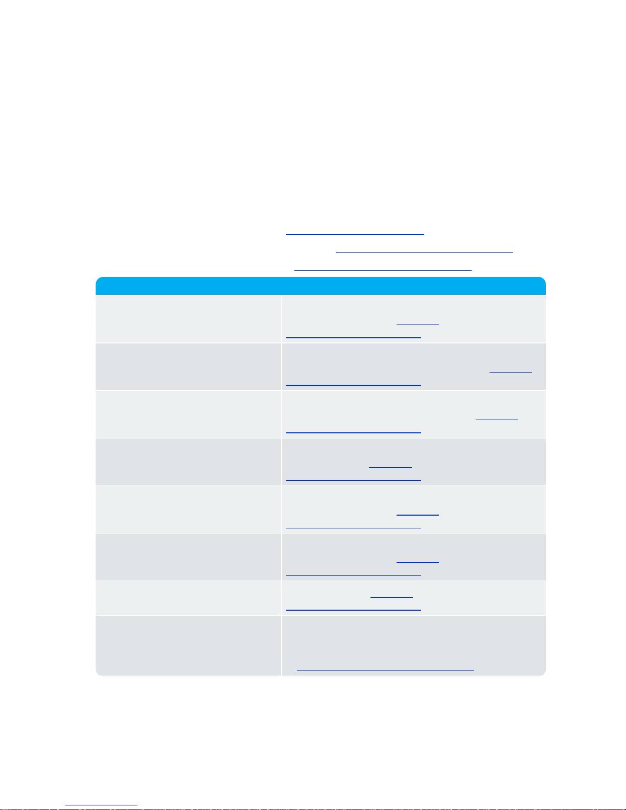
Subject Documentation
Spectralink Handset For more information about the handset, refer to the user
guide available online at http://sup-
port.spectralink.com/products.
Site Survey Function in Handset User
Guide
For more information about the site survey function in
handset, refer to the guide available online at http://sup-
port.spectralink.com/products.
Synchronization and Deployment
Guide
For more information about synchronization and deployment, refer to the guide available online at http://sup-
port.spectralink.com/products.
Spectralink IP-DECT/DECT Server For more information about the server, refer to the guide
available online at http://sup-
port.spectralink.com/products.
Spectralink DECT Repeater For more information about the repeater, refer to the
guide available online at http://sup-
port.spectralink.com/products.
Provisioning Guide For more information about provisioning, refer to the
guide available online at http://sup-
port.spectralink.com/products.
Spectralink Technical Bulletins Available online at http://sup-
port.spectralink.com/products.
Release Notes Document that describes software changes, bug fixes,
outstanding issues, and hardware compatibility considerations for new software releases. Available online
at http://support.spectralink.com/products.
Spectralink Digital DECT Base Station Installation Guide
Page 5

14219104-IG, Edition 4.0
June 2017, Originaldocument
5
Subject Documentation
Spectralink DECT Training material In order to gain access to the Spectralink training mater-
ial, you must attend training and become Spectralink Certified Specialist.
Please visit http://-
partneraccess.spectralink.com/training/classroom-training for more information and registration.
Spectralink Digital DECT Base Station Installation Guide
Page 6

14219104-IG, Edition 4.0
June 2017, Originaldocument
6
Description of Base Station
The Spectralink Digital DECT Base Station is only intended for use with a Spectralink DECT Server
2500/8000. The Spectralink Digital DECT Base Station is not intended to be connected directly to
the PSTN network.
The Spectralink Digital DECT Base Station is designed with two internal antennas and supports
antenna diversity.
The Spectralink Digital DECT Base Station is designed with connector for External Antenna.
The Spectralink Digital DECT Base Station is also able to carry out a handover between the RF
channels under the same Spectralink Digital DECT Base Station, and handles 4 or 8 DECT speech
channels simultaneously.
The Spectralink Digital DECT Base Station is able to frame synchronize with other Spectralink
Digital DECT Base Stations under the same Spectralink DECT Server. Cable length is up to 2
km/1.2 miles on a twisted pair, cat. 5e or higher, between the Spectralink Digital DECT Base Station
and Spectralink DECT Server.
The Spectralink Digital DECT Base Station is also power supplied from this connection (maximum
supply 1.5 W).
The DECT radius of coverage is up to 600 meters/2000 feet with a handset in free sight.
Spectralink Digital DECT Base Station Installation Guide
Page 7

14219104-IG, Edition 4.0
June 2017, Originaldocument
7
Installing the Base Station
Below you will find information about installing the base station.
Note:
Before you install the equipment, ensure that a site planner defines the location of the
base stations.
Before you begin the installation, determine the position of the base station for best coverage. The average coverage within buildings is 75 meters/245 feet.
The coverage depends on the construction of the building, architecture, and the choice of
building materials.
Frequency Bands
l EMEA, Australia & New Zealand: 1G8: 1880 – 1900 MHz
l South America: 1G9: 1910 – 1930 MHz
l USA & Canada: 1G9: 1920 – 1930 MHz (DECT 6.0)
Environmental Considerations
l Do not install a device near metal objects and steel constructions.
l Do not position devices in ducts, plenums or hollow spaces used to transport environmentalair
except where the duct, plenum or hollow space is created by a suspended ceiling having lay-in
panels.
l Do not position devices behind furniture.
l The installation area must be clean, free of traffic and excess dust, dry, and well ventilated.
l The installation area must be within the temperature ranges of 10°C and 40°C/50°F and
104°F.
l The installation area must be between 20% and 80% non-condensing relative humidity.
l For best RF coverage, the device must be mounted vertically on walls.
Power Requirements for the Base Station
The Spectralink Digital DECT Base Station is powered directly via the Spectralink DECT Server
2500/8000 Base Station Interface Card (BIF card).
Spectralink Digital DECT Base Station Installation Guide
Page 8

14219104-IG, Edition 4.0
June 2017, Originaldocument
8
Base Station Appearence and Components
Below you will find a description of the base station appearance and components:
Digital DECT Base Station - rear
1. Holesfor wall mounted screws
2. Connection to server
Digital DECT Base Station - front
1. LED
Spectralink Digital DECT Base Station Installation Guide
Page 9

14219104-IG, Edition 4.0
June 2017, Originaldocument
9
Digital DECT Base Station - front
1. RJ45 port
Base Station LED Indicators
Below you will find information about LED indicators on the base station.
Front Cover
The base station front cover has one indicator describing the base station faults and failures. The
indicator is off when the base station is not powered. The LED flashes when the base station initializes. The indicator is on when the base station is operating.
LED Indicator Meaning
Steady green OK and idle
Slow green flashing OK and active voice call
Fast green flashing Base station is initializing or busy (all channels are in
use)
Red flashing Updating firmware in base station
Steady red Just powered on
Spectralink Digital DECT Base Station Installation Guide
Page 10

14219104-IG, Edition 4.0
June 2017, Originaldocument
10
LED Indicator Meaning
Steady red for 5 seconds followed by
fast red flashing
Reset to factory settings
Spectralink Digital DECT Base Station Installation Guide
Page 11

14219104-IG, Edition 4.0
June 2017, Originaldocument
11
How to Wall Mount the Base Station
The base station must be mounted vertically on the wall for best coverage.
1. Use a twisted pair cable, cat. 5e or higher, between the base station and Spectralink DECT
Server with an RJ45 connector at the base station end of the cable. Connect the cable to the
plug using the two inner connectors of the plug. Pins 4 and 5 for the first 4 channels, and pins 3
and 6 for the last 4 channels.
Note:
Cable dimensions must as a minimum correspond to those of AWG 26.
2. Mount the base station onto the wall using the screws accompanying the base station.
Note:
When you place the base station on the screws, ensure that the screws do not
touch the printed circuit board.
1. Holesfor wall mounted screws
2. Connection to server
3. Connect the base station to the Spectralink DECT Server.
Recording the Installation Information
After completing the installation of the base stations, record the location of each base station and
add a descriptive text in the web based Administration Page of the Spectralink DECT Server under
Base station/IP Base Station.
Spectralink Digital DECT Base Station Installation Guide
Page 12

14219104-IG, Edition 4.0
June 2017, Originaldocument
12
Product Compatibility
If you have any questions about product compatibility, contact your system administrator.
You can use the Spectralink Digital DECT Base Station and with other Spectralink products as identified by the type approval model ID and/or part number located on the label of the product.
Spectralink Base Station
Spectralink Digital DECT Base Station 4 channels K007
Spectralink Digital DECT Base Station 8 channels K007
Spectralink DECT Repeater
Spectralink DECT Repeater 1G8, 2 channels, with
external antenna
K018B (0244 0000)
Spectralink DECT Repeater 1G9, 2 channels, with
external antenna
K018B (0244 1000)
Spectralink DECT Repeater 1G8, 2 channels,
without external antenna
K018(0244 1100)
Spectralink DECT Repeater 1G9, 2 channels,
without external antenna
K018(0244 1200)
Spectralink DECT Repeater 1G8, 4 channels, with
external antenna
K018 (0244 1600)
Spectralink DECT Repeater 1G9, 4 channels, with
external antenna
K018 (0244 0200)
Spectralink DECT Repeater 1G8, 4 channels,
without external antenna
K018C (0233 4601)
Repeater Programming Kit 02509210
Spectralink Digital DECT Base Station Installation Guide
Page 13

14219104-IG, Edition 4.0
June 2017, Originaldocument
13
Spectralink Server
Spectralink DECT Server 2500 K017
Spectralink DECT Server 8000 K016
Power Supply, 19.0V (only Server 2500) 8476 9905
Power Supply, 19.0V (only Server 8000) 8476 9902
Cable for Power Supply: AU version 8468 7011
Cable for Power Supply: DK version 8468 7012
Cable for Power Supply: EU version 8468 7013
Cable for Power Supply: UK version 8468 7014
Spectralink Digital DECT Base Station Installation Guide
 Loading...