

SpectraLink IP-DECT Server 400, IP-DECT Server 6500, DECT Server 8000, DECT Server 2500 Synchronization And Deployment Manual
Page 1

14169000-IG, Edition 11.0
January 2018, Original document
Spectralink IP-DECT Server 400/6500 and DECT Server
2500/8000
Synchronization and Deployment
Guide
Page 2

Copyright Notice
© 2013 - 2017 Spectralink Corporation All rights reserved. SpectralinkTM, the Spectralink logo and
the names and marks associated with Spectralink’s productsare trademarks and/or service marks of
Spectralink Corporation and are common law marks in the United States and various other countries. All other trademarks are property of their respective owners. No portion hereof may be reproduced or transmitted in any form or by any means, for any purpose other than the recipient’s
personal use, without the express written permission of Spectralink.
All rights reserved under the International and pan-American Copyright Conventions. No part of this
manual, or the software described herein, may be reproduced or transmitted in any form or by any
means, or translated into another language or format, in whole or in part, without the express written
permission of Spectralink Corporation.
Do not remove (or allow any third party to remove) any product identification, copyright or other
notices.
Notice
Spectralink Corporation has prepared this document for use by Spectralink personnel and customers. The drawings and specificationscontained herein are the property of Spectralink and shall
be neither reproduced in whole or in part without the prior written approval of Spectralink, nor be
implied to grant any license to make, use, or sell equipment manufactured in accordance herewith.
Spectralink reserves the right to make changes in specifications and other information contained in
this document without prior notice, and the reader should in all cases consult Spectralink to determine whether any such changes have been made.
NO REPRESENTATION OR OTHER AFFIRMATION OF FACT CONTAINED IN THIS
DOCUMENT INCLUDING BUT NOT LIMITED TO STATEMENTS REGARDING CAPACITY,
RESPONSE-TIME PERFORMANCE, SUITABILITY FOR USE, OR PERFORMANCE OF
PRODUCTS DESCRIBED HEREIN SHALL BE DEEMED TO BE A WARRANTY BY
SPECTRALINK FOR ANY PURPOSE, OR GIVE RISE TO ANY LIABILITY OF SPECTRALINK
WHATSOEVER.
Warranty
The Product Warranty and Software License and Warranty and other support documents are available at http://support.spectralink.com/.
Contact Information
US Location
+ 1 800-775-5330
Spectralink Corporation
2560 55th Street
Boulder, CO 80301
USA
info@spectralink.com
UK Location
+44 (0) 20 3769 9800
Spectralink Europe UK
329 Bracknell, Doncastle Road
Bracknell, Berkshire, RG12 8PE
United Kingdom
infoemea@spectralink.com
Denmark Location
+45 75602850
Spectralink Europe ApS
Bygholm Søpark 21 E Stuen
8700 Horsens
Denmark
infoemea@spectralink.com
Page 3

Contents
Introduction 5
Scope 5
Before You Begin 5
Related Documentation 6
Terminology and Acronyms 7
AboutSynchronization 10
Types of Synchronization 10
Off-site Planning, Prior to Visit 11
If Customer Wants to Replace Existing IP-DECT/DECT System 11
Is it an IP-DECT base station or a digital DECT base station? 11
Investigate Site 11
"Conclusion" 13
On-site Investigation 14
Aligning Expectations With Customers 14
On-site Deployment 15
Deployment Tools 15
Important Parameters 17
Deployment Rules of Thumb 19
IP-DECT Base Station using Radio Synchronization (Over The Air) 19
Deployment Procedure 20
Placement of Base Stations 22
IP-DECT Base Stations using LAN Synchronization and Digital DECT
Base Stations 24
Deployment Procedure 25
Placement of Base Stations 27
LAN BasedSynchronization 29
Precision Time Protocol Background 29
Deployment of Base Stations 30
Network Requirements 30
Multicast 31
Timing and Jitter 31
Network Topology 32
Traffic Load 32
Quality and Configuration of the Switches 33
Configurations and Administrations 34
IP-DECT/DECT Server System Settings 34
Base Station Individual Settings 34
14169000-IG, Edition 11.0
January 2018, Original document
Page 4

Base Station Synchronization Status 35
Troubleshooting 36
Synchronization 36
14169000-IG, Edition 11.0
January 2018, Original document
Page 5

14169000-IG, Edition 11.0
January 2018, Original document
5
Introduction
This guide is intended for qualified technicians who will deploy Spectralink IP-DECT/DECT Server
Solutions. To qualify to deploy a IP-DECT/DECT Server Solution, you must have understood and
completed the technical training successfully. This guide covers both 1G8 and 1G9 deployment.
Scope
The Synchronization and Deployment Guide provides instructions and best practices for deployment
of the following solutions:
l Spectralink IP-DECT/DECT Server 8000 and 2500
l Spectralink IP-DECT/DECT Server 6500 and 400
The purpose of this guide is to familiarize you with the procedures that are needed to carry out a site
survey as well as understand the requirements to ensure synchronization is successfully implemented. At the completion of this guide you should be comfortable with the following:
l Using a handset to measure and record Q - and RSSI values (RF values).
l Selecting a proper mounting location for base stations and repeaters.
l Making sure that the company LAN meets the LAN Synchronization requirement limits, and
documenting the deployment.
Before You Begin
This guide assumes the following:
l You have a working knowledge of deployment in general
l You have completed the technical training
SpectralinkIP-DECT Server 400/6500 and DECT Server 2500/8000 Synchronization and Deployment Guide
Page 6

14169000-IG, Edition 11.0
January 2018, Original document
6
Related Documentation
For information about Server IP-DECT/DECT Server Solutions not covered by this manual, refer to
the following documentation:
Subject Documentation
Spectralink DECT Handset For more information about the handset,
refer to the user guide available online at
http://support.spectralink.com/products.
Site Survey Function in Handset For more information about the handset,
refer to the user guide available online at
http://support.spectralink.com/products.
Spectralink IP-DECT/DECT Server For more information about the server,
refer to the guide available online at
http://support.spectralink.com/products.
Spectralink Technical News Newsletter that describes software
changes, bug fixes, outstanding issues, and
hardware compatibility considerations for
new software releases. To subscribe, go to
www.spectralink.com.
Spectralink DECT Training material
SpectralinkIP-DECT Server 400/6500 and DECT Server 2500/8000 Synchronization and Deployment Guide
Page 7

14169000-IG, Edition 11.0
January 2018, Original document
7
Terminology and Acronyms
The table below refers to common terms and acronyms that are related to the Spectralink IPDECT/DECT solutions.
Term Definition
Deployment The act of locating the mounting location and installing base
stations and repeaters. System performance is dependant
on the deployment made - and, therefore, the survey performed.
Handover A process initiated by the handset in which the speech chan-
nel carrying an active conversation is passed from one base
station to another.
Erlang The erlang is a dimensionless unit that is used in telephony
as a measure of offered load or carried load on serviceproviding elements such as telephone circuits or telephone
switching equipment.
LED Light Emitting Diode
LI-Ion Lithium-Ion
Ni-MH Nickel -Metal Hydride
Q Value Signal Quality Factor value. An expression of the bit failure
rate in the communication between the handset and a base
station. The value has a max. of 64, equal to no bit errors
measured.
LAN synchronization Method for synchronizing IP base stations over LAN
Synchronization Over the Air (OTA) Method for synchronizing IP base stations over Air (radio)
SUOTA Software Update Over The Air
RF Radio Frequency
RSSI Value Radio Signal Strength Indication value. A relative expres-
sion for the signal strength of a base station as measured
by the handset at a given location.
Site survey A site survey comprises the act of locating the best places
for base stations by measuring RSSI levels with DECT
handsets. Complete survey consists of measuring with multiple base stations, combining RSSI and Q value reading in
real surroundings.
SpectralinkIP-DECT Server 400/6500 and DECT Server 2500/8000 Synchronization and Deployment Guide
Page 8

14169000-IG, Edition 11.0
January 2018, Original document
8
Term Definition
Speech channel A speech channel is used to carry communication between
the handset and the base station or repeater.
AC Authentication Code
ARI no. Access Rights Identity - Serial number of the (missing or
bad snippet).
CLI Command Line Interface
dB Decibels (deciBells)
DECT Digital Enhanced Cordless Telecommunications
DHCP Dynamic Host Configuration Protocol
DNS Domain Name System
e.i.r.p. Equivalent Isotropic Radiated Power
GAP Generic Access Profile
HW PCS Hardware Product Change Status - Hardware edition
IP Internet Protocol
IPEI International Portable Equipment Identity - Serial number
of the handset - SN
IWU Inter Working Unit
Spectralink IP-DECT Server Spectralink IP-DECT Server400/6500
Spectralink DECT Server Spectralink DECT Server2500/8000
LAN Local Area Network
MAC Media Access Control - hardware address of a device con-
nected to a network
MTU Maximum Translation Unit
MWI Message Waiting Indication
NIC Network Interface Card
NTP Network Time Protocol
PBX Private Branch eXchange
PCS Product Change Status (Edition)
PoE Power over Ethernet
SpectralinkIP-DECT Server 400/6500 and DECT Server 2500/8000 Synchronization and Deployment Guide
Page 9

14169000-IG, Edition 11.0
January 2018, Original document
9
Term Definition
PP Portable Parts - wireless handset
RSSI Received Signal Strength Indicator
RTP Real-time Transport Protocol
SIP Session Initiated Protocol
SW PCS Software Product Change Status - Software edition
TFTP Trivial File Transfer Protocol
UDP User Datagram Protocol
VoIP Voice over Internet Protocol
WLAN Wireless Local Area Network
WRFP Wireless Radio Fixed Part - Wireless Repeater
SpectralinkIP-DECT Server 400/6500 and DECT Server 2500/8000 Synchronization and Deployment Guide
Page 10

14169000-IG, Edition 11.0
January 2018, Original document
10
AboutSynchronization
In a multi-cell DECT system the base station radios must be synchronized to each other in order to
achieve the optimum handover experience, when handsets are moving around among base stations. Spectralink supports synchronization of digital DECT base stations via the wire and IP-DECT
base stations via the radio. Further, IP-DECT base stations can use corporate LAN for synchronization as well.
Types of Synchronization
l LAN Based Synchronization (Server 400/6500/2500/8000)
l Radio Based Synchronization (Over The Air) (Server 400/6500/2500/8000)
l Digital DECT Base Stations (Server 2500/8000)
Note:
Synchronization of digital DECT base stations is controlled by the server and
requires no configuration. Therefore, configuration of digital DECT base stations
will not be described further.
SpectralinkIP-DECT Server 400/6500 and DECT Server 2500/8000 Synchronization and Deployment Guide
Page 11

14169000-IG, Edition 11.0
January 2018, Original document
11
Off-site Planning, Prior to Visit
Below you will find at list of questions and considerations to take into account during the planning
phase prior to visiting a site.
If Customer Wants to Replace Existing IP-DECT/DECT
System
Is it an IP-DECT base station or a digital DECT base station?
l IP-DECT base station:
o
Consider PoE, Active equipment, Switch PoE.
o
Is this reusable for the new system?
o
Do LAN switches support LAN synchronization?
l Digital DECT base station:
o
Can the cabling be reused? (yes/no/partly)
Investigate:
o
Is all cabling twisted pair end to end (recommended equal to CAT5e)? Is cabling
present where DECT coverage is needed?
o
Are all junction points of good quality?
o
From these investigations the costs to get cabling up to a satisfactory standard can be
estimated.
Note:
Today new systems can be a combination of wired and IP.
Investigate Site
l What is the site?
o
Are there more buildings?
o
If there are more buildings - consider the distance between the buildings, and whether it
is possible to establish synchronization between base stations.
o
Are there more sites (sub-sites)?
o
If there are several sites - the remote site(s) (i.e. those where it will not be possible to
establish synchronization) must be IP-DECT/DECT system(s).
l Study blueprints of building
SpectralinkIP-DECT Server 400/6500 and DECT Server 2500/8000 Synchronization and Deployment Guide
Page 12

14169000-IG, Edition 11.0
January 2018, Original document
12
o
Consider the building materials
o
More dense materials means less radio propagation and therefore more base stations
o
Environment
o
Moving interior (warehouse, production facility). Much equipment moving around will
influence the propagation
o
Metal can cause reflections which will influence propagation (i.e. metal blinds, metal
beams, metal shelves, rebars, shielding foils)
o
Where are fire doors/walls placed? These will influence propagation
l System usage
o
Where are people placed? (those that will use the IP-DECT/DECT system)?
o
Are there areas with (extra) high voice-traffic load like:
o
Canteen
o
Nurse office
o
Etc.
l Rough estimation of equipment (if possible)
A rough/budgetary estimate of equipment/base stations can be calculated according to below:
o
Open area (indoor)
o
Office area
o
DECT systems: [Size of area to cover in m2]/800 = number of digital DECT base stations Necessity: approximately 25 m between the base stations and 15 m overlap to
enable handover.
o
IP-DECT systems (Radio Synchronization): [Size of area to cover in m2]/600 = number
of LAN base stations Necessity: approximately 22 m between the base stations and
overlap from base station to base station.
IP-DECT system (LAN synchronization): [Size of area to cover in m2]/800 = number of
LAN base stations Necessity: approximately 25 m between the base stations and 15 m
overlap to enable handover.
Note:
Be aware that this will not be an exact figure. A deployment of the site will be
necessary to get a correct number.
SpectralinkIP-DECT Server 400/6500 and DECT Server 2500/8000 Synchronization and Deployment Guide
Page 13

14169000-IG, Edition 11.0
January 2018, Original document
13
"Conclusion"
Based on the above analysis, the installer must be able to determine whether to install a Spectralink
DECT Server or Spectralink IP-DECT Server or a combination.
l IP-DECT/DECT systems with IP-DECT base stations can benefit from synchronization over
LAN
l Digital DECT base stations have 4/8 channels whereas IP-DECT base stations have 11 chan-
nels
l Digital DECT base stations and IP-DECT base stations with LAN synchronization can have
longer distance between base stations as opposed to IP-DECT base stations with Radio synchronization (Over The Air (OTA)).
Synchronization is essential for handing over calls from one base station to another.
Radio Synchronization (OTA)
LANSynchronization and Digital DECT Base
Stations
Note:
Before going on a site, remember to have confirmation from the customer regarding accessibility to all areas where the customer needs IP-DECT/DECT to make
measurements for deployments.
SpectralinkIP-DECT Server 400/6500 and DECT Server 2500/8000 Synchronization and Deployment Guide
Page 14

14169000-IG, Edition 11.0
January 2018, Original document
14
On-site Investigation
Below you will find considerations to take into account when investigating a site.
Aligning Expectations With Customers
l Start your on-site visit with meeting the customer and align expectations to coverage (areas)
and dropped calls (expect 2-3-% dropped calls).
l Take a walk around the premises to create an overview and check that the information
uncovered during the pre-planning phase is correct/valid.
Consider:
o
internal structure material
o
moving interior
o
are there materials that affect/absorb propagation
o
is the interior as expected?
l Create a rough overall plan for how to execute the deployment.
l If deploying IP-DECT base stations with Radio synchronization, create a blueprint with base
station placement and synchronization chain.
SpectralinkIP-DECT Server 400/6500 and DECT Server 2500/8000 Synchronization and Deployment Guide
Page 15

14169000-IG, Edition 11.0
January 2018, Original document
15
On-site Deployment
Deployment Tools
Bring the following tools on a site for deployment:
l 1 Spectralink IP-DECT Server 400
l 1 Battery pack min. 8V/max. 60V
l 1 Tripod (app 2m high)
l 1 Cable with RJ45 plug (pin 1 must be connected to pin 3, pin 2 must be connected to pin 6)
Note:
Preferably the tripod shall place the Spectralink IP-DECT Server 400 at the height
where you will place the server/base stations/repeaters in the final installation.
If 2 people perform the deployment at IP-DECT sites, you shall also bring:
l Minimum 1 Spectralink DECT repeater (the repeater must be set up to synchronize on the
Spectralink IP-DECT Server 400 used for the deployment).
l 9V Battery pack
l 1 Tripod (app 2m high)
l 1 Cable to connect battery pack and Spectralink DECT repeater (with RJ11 plug in for the
repeater) For a description of pin connections, see the information on the Power Supply.
SpectralinkIP-DECT Server 400/6500 and DECT Server 2500/8000 Synchronization and Deployment Guide
Page 16

14169000-IG, Edition 11.0
January 2018, Original document
16
Also bring:
l 2 handsets
o
1 Spectralink Standard Handset (7522/7532, 7622/7642, 7722/7742).
Note:
The handset can only measure correctly when off hook.
When measuring, carry the handset with your hands covering the antennas to
assimilate normal user conditions (heads or surroundings blocking the radio signals when holding the handset to the ear).
o
1 Spectralink DECT Handset of any type.
l Consider also to bring a device you can use to play sound in the handset.
l A good idea would be also to bring a laptop with network cable to connect with the Spectralink
IP-DECT Server 400.
l If you bring a repeater, you should also bring power supply for the repeater, and repeater pro-
gramming kit (Product ID: 02509210).
l When bringing a repeater, you must also bring a serial to USB converter to be able to connect
the repeater to the laptop.
l It could also be beneficial to bring a power supply for the Spectralink IP-DECT Server 400.
For more information about using the handset for deployment, see Site Survey Function in Handset
User Guide.
SpectralinkIP-DECT Server 400/6500 and DECT Server 2500/8000 Synchronization and Deployment Guide
Page 17
14169000-IG, Edition 11.0
January 2018, Original document
17
Important Parameters
When deploying, there are 3 parameters which are equally important:
l RSSI values: Value indicating signal strength
l Q value: Value indicating the signal quality (preferably steady at 64)
l Sound Quality: Measured by walking away from the base station with the handset and meas-
ure where the RSSI value drops below 75 and the Q value stays constant at 64.
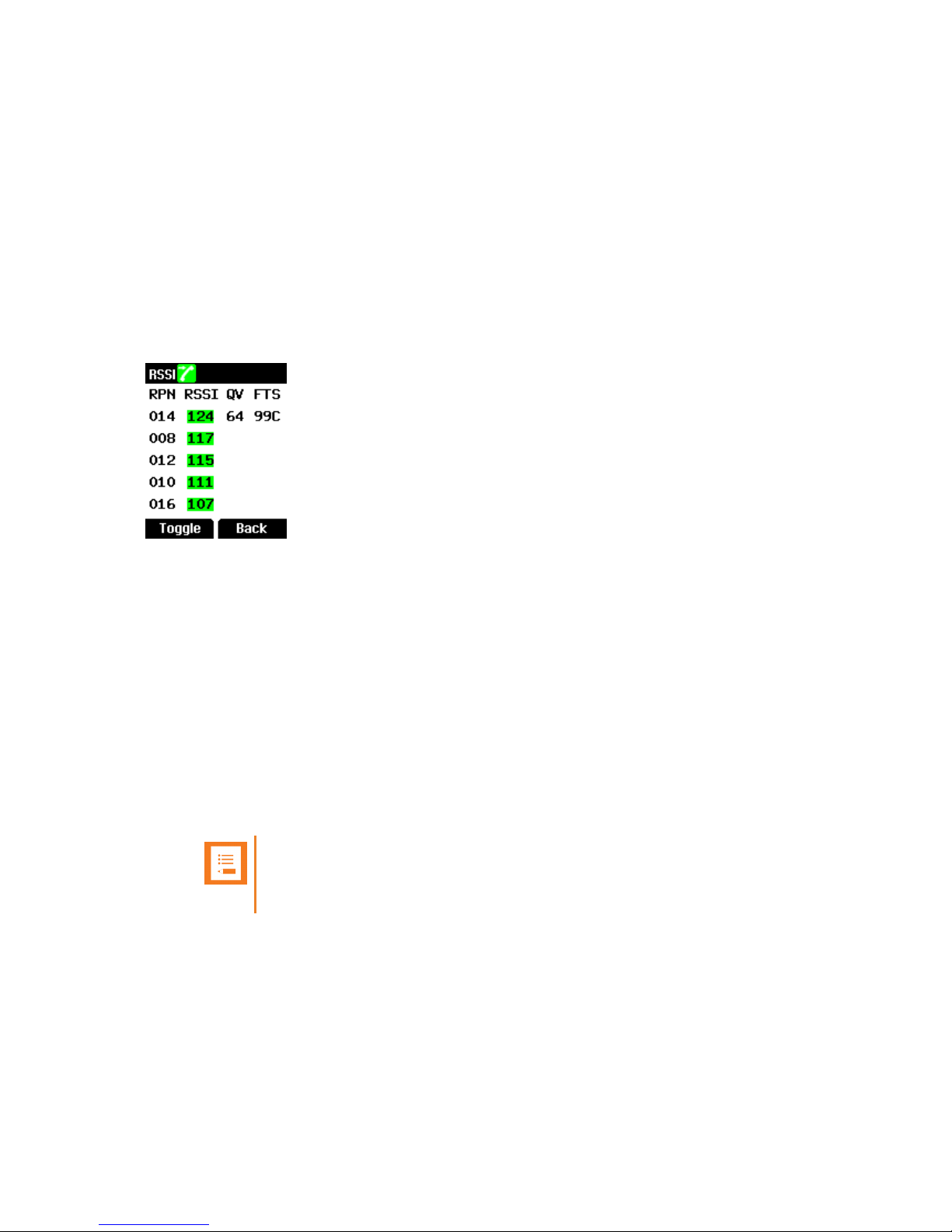
Example and Description of Values (RPN, RSSI, Quality) (Only relevant to Spectralink
Handset 7202/7212/7522/7532/7622/7642/7722/7742)
Descriptions of the values above:
l RPN (Radio Part Number) values range from 0 - 255.
l RSSI (Received Signal Strength Indicator) values range from 35 - 124. Counting down from
124.
l QV (Quality) values range from 0-64.
A signal quality of 64 is a connection without errors, this number will be reduced by one for
each error (such as reflections or noise). Preferably this value should be steady at 64.
l FTS ( Frequency, Timeslot, State)
o
Time slot values range from 0 to B (there are 12 time slots)
o
State: E = Economy mode active. B, C indicates if last handover was a connection handover or a bearer handover.
Note:
To only see handover type, disable Economy mode in the handset menu (Settings > Advanced > Economy mode).
l First line shows that the actual base station has RPN number 14, signal strength (RSSI) 124,
signal quality of connection is 64, 99C means ninth frequency, time slot 9, and that the last handover was a connection handover (C).
l Last four lines are candidates for connection handover (if any). Only the RSSI value and the
RPN value is shown.
SpectralinkIP-DECT Server 400/6500 and DECT Server 2500/8000 Synchronization and Deployment Guide
Page 18

14169000-IG, Edition 11.0
January 2018, Original document
18
Descriptions of RSSI colours:
RSSI
Green > 80 RSSI/- 70 dBm
Yellow < 80 RSSI/- 70 dBm and
> 70 RSSI/- 80 dBM
Red < 70 RSSI/- 80 dBM
Example and Description of Values (RPN, RSSI, Quality) (Only relevant to Spectralink
Handset Butterfly)
Below is an example of RPN values:
l The hexadecimal numeral system is used to describe RPN values and time slots. RPN values
range from 00 to FF.
l Time slot values range from 0 to B (there are12 time slots)
l Third line shows that the actual base station has RPN number 8, signal quality of connection is
64, signal strength (RSSI) 108, 3BC means third frequency, time slot B, and that the last handover was a connection handover (C).
l A signal quality of 64 is a connection without errors, this number will be reduced by one for
each error (such as reflections or noise). Preferably this value should be steady at minimum
64.
l The value of signal strength range from 110 to 35. Counting down from 110.
To Check RSSI values in Handset
1. Press Menu to enter main menu.
2. Scroll to Status, and press Select.
3. Scroll to RSSI, and press Select. The bearer quality is shown in the display.
SpectralinkIP-DECT Server 400/6500 and DECT Server 2500/8000 Synchronization and Deployment Guide
Page 19

14169000-IG, Edition 11.0
January 2018, Original document
19
Deployment Rules of Thumb
l Be systematic
l Document
l Do not assume - Measure
IP-DECT Base Station using Radio Synchronization
(Over The Air)
Note:
It is recommended to deploy a system as a star system with the sync master placed in the
middle.
Necessary overlap in synch chains Necessary overlap between synch chains
SpectralinkIP-DECT Server 400/6500 and DECT Server 2500/8000 Synchronization and Deployment Guide
Page 20

14169000-IG, Edition 11.0
January 2018, Original document
20
Deployment Procedure
Start by placing your tripod with the Spectralink IP-DECT Server 400 (from your deployment tools)
where you plan the first base station (the sync master) to be:
Take picture of the placement and note it on a blueprint of the building.
l Remember to consider that the first base station (sync master) shall be placed centrally in the
installation so the rest of the system can spread from it (remember to consider all 3 dimensions.
Note:
Take picture of the placement and note it on a blueprint of the building.
l Make a call between the two handsets. During the deployment there must always be an active
call established.
Note:
Measurements are only valid on handsets in a connected call!
l Play music/talk into the handset without headset. Wear the headset and listen to the sound
quality all the time.
l At the same time as listening to the sound quality, use your handset to measure how far the
base station will cover sufficiently.
This is done by walking away from the base station with the handset and measure where the
RSSI value drops below 75 and the Q value stays constant at 64. Do this in all directions from the base.
For a description of the parameters and RPN values, see "Important Parameters" on page 17.
Note:
The handset can only measure correctly when off hook.
When measuring, carry the handset with your hands covering the antennas to
assimilate normal user conditions (heads or surroundings blocking the radio signals when holding the handset to the ear).
l To perform a site survey using a Spectralink Standard Handset (7522/7532,7622/7642,
7722/7742), enter Survey mode on the handset. For more information about using the
SpectralinkIP-DECT Server 400/6500 and DECT Server 2500/8000 Synchronization and Deployment Guide
Page 21

14169000-IG, Edition 11.0
January 2018, Original document
21
handset for deployment, see Site Survey Function in Handset User Guide.
Note:
It is important to measure all places where coverage is required.
Do not assume that there is coverage - it has to be measured!
l Consider where to place the next base station so that the handset gets opportunity to han-
dover to the next base station. Determine where to place the next base stations.
l Move your tripod with the Spectralink IP-DECT Server 400 to the next placement.
Note:
Take picture of the placement and note it on a blueprint of the building.
l Continue until the whole site is deployed.
Note:
Remember to document each placement for base stations (incl. sync master).
o
Take pictures of where exactly the base station must be placed.
o
Note it on a drawing of the premises.
SpectralinkIP-DECT Server 400/6500 and DECT Server 2500/8000 Synchronization and Deployment Guide
Page 22

14169000-IG, Edition 11.0
January 2018, Original document
22
Placement of Base Stations
When determining where to place the base stations, following points must be considered:
l To get maximum coverage from a base station the base stations must be as visible as pos-
sible.
l A guideline can be to consider where a light bulb can be placed to light up the maximum area.
RSSI 75
l Traffic – how many simultaneous calls can be expected in an area.
o
In an assembly area e.g. in a canteen there will probably be many simultaneous calls during lunch.
o
To get an estimate of the simultaneous calls Erlang can be calculated.
SpectralinkIP-DECT Server 400/6500 and DECT Server 2500/8000 Synchronization and Deployment Guide
Page 23

14169000-IG, Edition 11.0
January 2018, Original document
23
l Sync latency in sync chains.
l Propagation through building materials – dense materials influence propagation negatively.
Base stations shall be placed away from reflecting materials like metal.
l Base stations shall be placed away from other DECT base stations.
l “When in doubt deploy”, i.e. to ensure a good coverage place one more rather than one less
base station.
l A good documentation of the deployment is needed to build the synchronization chains.
Note:
Take picture of the placement and note it on a blueprint of the building.
SpectralinkIP-DECT Server 400/6500 and DECT Server 2500/8000 Synchronization and Deployment Guide
Page 24

14169000-IG, Edition 11.0
January 2018, Original document
24
IP-DECT Base Stations using LAN Synchronization and
Digital DECT Base Stations
In IP-DECT/DECT systems, it is important to ensure an overlap on the base stations at all timers of
15 m to ensure a call can be handed over at normal walking speed.
Note:
Synchronization between the digital DECT base stations is not an issue in these systems, as synchronization between the base stations is handled automatically by the
DECT servers.
SpectralinkIP-DECT Server 400/6500 and DECT Server 2500/8000 Synchronization and Deployment Guide
Page 25

14169000-IG, Edition 11.0
January 2018, Original document
25
Deployment Procedure
Start by placing your tripod with the Spectralink IP-DECT Server 400 (from your deployment tools)
where you plan the first base station to be:
l Place the first base station in a corner of the building so there is coverage in the corner.
Note:
Take picture of the placement and note it on a blueprint of the building.
l Make a call between the two handsets. During the deployment there must always be an active
call established.
Note:
Measurements are only valid on handsets in a connected call!
l Play music/talk into the handset without headset. Wear the headset and listen to the sound
quality all the time.
l At the same time as listening to the sound quality, use your handset to measure how far the
base station will cover sufficiently.
This is done by walking away from the base station with the Site Survey Handset and measure where the RSSI value drops below 70 and the Q value stays constant at 64. Do this
in all directions from the base stations.
For a description of the parameters and RPN values, see "Important Parameters" on page 17.
Note:
The handset can only measure correctly when off hook.
When measuring, carry the handset with your hands covering the antennas to
assimilate normal user conditions (heads or surroundings blocking the radio signals when holding the handset to the ear).
l To perform a site survey using a Spectralink Standard Handset (7522/7532,7622/7642,
7722/7742), enter Survey mode on the handset. For more information about using the
SpectralinkIP-DECT Server 400/6500 and DECT Server 2500/8000 Synchronization and Deployment Guide
Page 26

14169000-IG, Edition 11.0
January 2018, Original document
26
handset for deployment, see Site Survey Function in Handset User Guide.
Note:
It is important to measure all places where coverage is required.
Do not assume that there is coverage - it has to be measured!
l Note how far the place is from the tripod with the Spectralink IP-DECT Server 400.
l Find the next place for the base station app 2 x the above distance from the first placement
l Consider where to place the next base so that the handset gets opportunity to handover to the
next base station.
l Move your tripod with the Spectralink DECT Server 400/2500. and measure whether this will
give sufficient overlay (i.e. RSSI value min 70, Q value stays constant at 64 and good sound
quality) at the same place as measured at the previous placement.
l If necessary, move the base station to get sufficient overlay.
l When it is determined where to place the next base stations.
Note:
Take picture of the placement and note it on a blueprint of the building.
l Continue until the whole site is deployed.
Note:
Remember to document each placement for base stations (incl. sync master).
o
Take pictures of where exactly the base station must be placed.
o
Note it on a drawing of the premises.
SpectralinkIP-DECT Server 400/6500 and DECT Server 2500/8000 Synchronization and Deployment Guide
Page 27

14169000-IG, Edition 11.0
January 2018, Original document
27
Placement of Base Stations
When determining where to place the base stations, following points must be considered:
l To get maximum coverage from a base station the base stations must be as visible as pos-
sible.
l A guideline can be to consider where a light bulb can be placed to light up the maximum area.
RSSI 70
l Traffic – how many simultaneous calls can be expected in an area.
o
In an assembly area e.g. in a canteen there will probably be many simultaneous calls during lunch.
o
To get an estimate of the simultaneous calls Erlang can be calculated.
l Propagation through building materials – dense materials influence propagation negatively.
Base stations shall be placed away from reflecting materials like metal.
l Base stations shall be placed away from other DECT base stations.
SpectralinkIP-DECT Server 400/6500 and DECT Server 2500/8000 Synchronization and Deployment Guide
Page 28

14169000-IG, Edition 11.0
January 2018, Original document
28
l “When in doubt deploy”, i.e. to ensure a good coverage place one more rather than one less
base station.
l A good documentation of the deployment is needed to build the synchronization chains.
Note:
Take picture of the placement and note it on a blueprint of the building.
SpectralinkIP-DECT Server 400/6500 and DECT Server 2500/8000 Synchronization and Deployment Guide
Page 29

14169000-IG, Edition 11.0
January 2018, Original document
29
LAN BasedSynchronization
Below you will find a description of how LAN based synchronization works, and what must be considered when synchronizing.
Note:
LAN based synchronization only works when using a Spectralink Handset.
The latest generation of Spectralink IP-DECT Base Station s support the use of corporate Local
Area Network (LAN) for synchronization of the DECT radios when running software release
PCS15C or later.
In a multi-cell DECT system, the base station radios must be synchronized to each other in order to
achieve the optimum handover experience, when handsets are moving around among base stations. Spectralink supports the synchronization of digital DECT base stations via the wire and IPDECT base stations via the radio. IP-DECT base stations can use the LAN for synchronization as
well.
The LAN based synchronization has several advantagesover synchronizing via the radio. The configuration is much simpler because no synchronization chains need to be configured and maintained.
The synchronization is self-healing, because the system itself can handle if any base station is failing.
Finally, the system can be deployed with fewer base stations, because the base stations are no
longer required to be in range of each other.
It may, however, not be the ideal solution in all cases. LAN based synchronization requires that the
base stations involved in a handover are on the same network segment and the network deployment
(including LAN switches) meets a number of quality criteria.
Precision Time Protocol Background
Precision Time Protocol version 2 (PTPv2) is used to synchronize the radios of the IP-DECT base
station via the LAN. PTPv2 is defined in the standard IEEE 1588-2008 and a brief introduction can
be found here: http://en.wikipedia.org/wiki/Precision_Time_Protocol.
PTPv2 is based on a master-slave architecture, where the active master is automatically selected
among the base stations with the lowest serial number. Each network segment will have one active
master and the remaining base stations will be slaves. If the current master is failing a new one will
be automatically selected without disrupting the current synchronization state.
The PTPv2 datagrams are sent as multicast and transported via UDP on IPv4 or IPv6 or as raw Ethernet packets without IP.
The LAN based synchronization is administrated centrally from the web based Administration Page
of the IP-DECT/DECT Server. The synchronization itself however is handled autonomously by the
base stations, and the server is not involved and hence does not need to be on the same network
segment.
SpectralinkIP-DECT Server 400/6500 and DECT Server 2500/8000 Synchronization and Deployment Guide
Page 30

14169000-IG, Edition 11.0
January 2018, Original document
30
Deployment of Base Stations
When the base station radios are synchronized via radio, the base stations that synchronize to each
other must be within radio coverage of each other. This is not required when LAN based synchronization is used. Here, the deployment requirements are the same as for the digital DECT base
stations and the coverage overlap is only required for the handsets to be able to perform handovers.
The figure below illustrates the difference in coverage requirementsfor radio and LAN based synchronization.
Radio synchronization LAN synchronization
It should be noted that depending on the deployment - Synchronization via LAN and radio can be
combined in the same DECT installation. Even when a base station is configured to synchronize via
LAN, it transmits the signal required for synchronization via radio. Therefore, base stations synchronizing via radio can retrieve their synchronization signal from a base station synchronizing via
LAN. The other way around is not possible.
Network Requirements
For PTPv2 to work the requirements for the network are quite strict with regard to:
l multicast
l timing
Note:
LAN synchronization only works properly if multicast and timing requirements are met.
An assessment of the corporate LAN network MUST be done to evaluate if the LAN network is suitable enough for LAN based synchronization.
SpectralinkIP-DECT Server 400/6500 and DECT Server 2500/8000 Synchronization and Deployment Guide
Page 31

14169000-IG, Edition 11.0
January 2018, Original document
31
Multicast
The PTPv2 multicast packets cannot traverse routers and consequently the IP-DECT base stations
that needs to be synchronized must be on the same switched network segment.
Regardless of the transport selected, IPv4, IPv6 or Ethernet, the network switches must allow multicast traffic to and from all the LAN base stations. The multicast addresses used are listed below:
Protocol Multicast address
IPv4 224.0.1.129
IPv6 FF02::181
Ethernet 01:1B:19:00:00:00
If IPv4 or IPv6 is used as transport and IGMP snooping
(http://en.wikipedia.org/wiki/IGMP_snooping) is supported by the switch, the switch can utilize this to
automatically configure on which ports the multicast packets should be sent. Note that this requires
an IGMP querier to be present on the network segment (many IGMP snooping switches offers this
functionality).
If multicast is not working properly on the network, the IP-DECT base stations will not be able to
achieve LAN synchronization.
Timing and Jitter
For PTPv2 to be accurate enough to synchronize the DECT radios the network jitter must be low,
that is the network packet delay must be close to constant.
The PTPv2 algorithms in the base stations have built-in filtering, which make them able to cope with
some level of jitter. However, prolonged periods of large jitter can cause unstable or even loss of synchronization.
The corporate LAN must support the following specifications:
l Maximum of 500 nanoseconds jitter of multicast Ethernet packets between all IP-DECT base
stations being synchronized.
l Any single switch in the network cannot exceed 100nsec of jitter.
l PTPv2 event traffic must be given strict priority over all other network traffic.
l Multicast and the IGMP protocol (if used) must be configured per Spectralink requirements.
l Network topology
l The traffic patterns on the network
l The quality and configuration of the switches
SpectralinkIP-DECT Server 400/6500 and DECT Server 2500/8000 Synchronization and Deployment Guide
Page 32

14169000-IG, Edition 11.0
January 2018, Original document
32
Network Topology
Every time a PTPv2 packet passes through a switch - jitter is potentially added. Therefore, the number of switches between all base stations must be kept low. Because every individual base station
can assume the role as PTPv2 master or slave regardless of its position in the network topology, a
worst case position of master and slave must be considered when deploying the base stations in the
network. The figure below illustrates this with a core switch with two access switchesconnected.
Here the worst case path length is three switches.
Note:
In the lab, the IP-DECT base stations have successfully been synchronized with 5 enterprise LAN switches between master and slave.
Traffic Load
The traffic load on the switches will also affect the jitter. High traffic load and especially a large number of large packets will increase the jitter. For example, a 1500 bytes data packet introduces an
immediate 120 usec delay on a 100 Mbps link.
It is recommended that the core network links provides higher bandwidth than the access links, i.e. if
the access links are 100 Mbps, the uplink and core network should be at least 1 Gbps. This will alleviate the probability of traffic saturating the network path used for the base station synchronization.
If the traffic load causes problems for the base station synchronization, it may be necessary to separate the base stations from the data network. Be aware that separation via VLAN may not help as it
is still using the same physical link.
SpectralinkIP-DECT Server 400/6500 and DECT Server 2500/8000 Synchronization and Deployment Guide
Page 33

14169000-IG, Edition 11.0
January 2018, Original document
33
Quality and Configuration of the Switches
The LAN based synchronization is highly dependent on the quality and configuration of the deployment network. The single most important property of the switchesin the network is their ability to forward multicast Ethernet packets with low jitter, i.e. close to a constant delay. The total forwarding
jitter added by switches on any path through the deployment network should be less than one microsecond and preferably less than 100 nanoseconds.
Unfortunately, it is usually difficult to find the forwarding jitter specified for a given switch. Lab tests
indicates that enterprise level switches generally has adequately low forwarding jitter, whereas
SOHO and unmanaged switchesoften do not meet the requirements and thus must not be used.
When configuring the deployment network, multicast setup is critical for LAN synchronization to
work. Multicast is usually either blocked, forwarded as broadcast to all ports, forwarded according to
static configuration or forwarded to selected ports learned by IGMP snooping. The simplest option is
to forward as broadcast to all ports, but this might create unwanted traffic on unrelated network
parts. When using static configuration, the relevant multicast addresses listed earlier must be forwarded to the ports forming the deployment network. Enabling IGMP snooping on the switches
allow them to automatically configure which ports the multicast packet should be forwarded to, minimizing the network load caused by the LAN synchronization. In order to keep the multicast configuration updated, a IGMP querier must be present in the network – this functionality can be enabled
in many enterprise class switches.
Traffic Priority:
All time critical PTPv2 packets sent by the LAN synchronization software is by default marked with
either an Expedited Forwarding (EF) (46/0x2e) priority for IPv4 and IPV6 packets or a Class of Service value of 7 for VLAN encapsulated Ethernet packets. This is to allow the switches to give preference to the LAN synchronization packets.
Since the Expedited Forwarding priority on IP packets is shared with voice RTP packets, this is not
sufficient to ensure strict priority over all other traffic for the PTPv2 events packets.
There are two possible solutions to this:
l Give the highest priority to a custom IP priority and configure the server to apply this IP priority
to PTPv2 traffic.
l Give the highest priority to multicast UDP packets on port 319 with the destination address
224.0.1.129 (IPv4) or FF02::181 (IPv6).
SpectralinkIP-DECT Server 400/6500 and DECT Server 2500/8000 Synchronization and Deployment Guide
Page 34

14169000-IG, Edition 11.0
January 2018, Original document
34
Configurations and Administrations
A few configuration settings on the Spectralink server's web based Administration Page are used to
control base station synchronization via LAN.
IP-DECT/DECT Server System Settings
The system wide settings for synchronization via LAN are located under Configuration > Wireless
Server > Base stations:
Field Setting
Default sync type This setting controls the default synchronization type for
new base stations. The following values can be selected:
l Free running
l Radio (default)
l LAN
LAN sync transport protocol This setting controls the protocol used as transport for
the PTPv2 packets used for synchronization. The following values can be selected:
l Ethernet
l IPv4 (default)
l IPv6
IPv4 is the default and recommended in most networks.
Base Station Individual Settings
Field Setting
Type This setting controls the synchronization type for specific
base station. The following values can be selected:
l Free running
l Radio
l LAN
l Gateway
SpectralinkIP-DECT Server 400/6500 and DECT Server 2500/8000 Synchronization and Deployment Guide
Page 35

14169000-IG, Edition 11.0
January 2018, Original document
35
Base Station Synchronization Status
The synchronization status is displayed on the Spectralink server'sweb based Administration Page
under Administration > Base Stations.
The Sync column displays a green icon for base stations that are currently running as slaves and a
blue one for the current master.
The Lost column displays the number of times the synchronization has been lost and a percentage
which is the ratio of time the base station has been without synchronization. The lost counter must be
low but is expected to grow slowly over time. The percentage will start high and must be zero after
some time.
SpectralinkIP-DECT Server 400/6500 and DECT Server 2500/8000 Synchronization and Deployment Guide
Page 36

14169000-IG, Edition 11.0
January 2018, Original document
36
Troubleshooting
In general, always check if there is newer software to be downloaded.
Synchronization
Symptom Problem Resolution
All base stations are synchronization masters.
Multicast traffic is blocked in
the network.
Enable multicast traffic on
all switches between the
base stations.
Synchronization is OK at startup but
fails after a short period.
IGMP snooping is active, but
no IGMP querier is present on
the network to refresh multicast group memberships
Add an IGMP querier to the
network or disable IGMP
snooping.
Base stations do not synchronize or
loose synchronization often.
The traffic between base stations is being delayed a varying amount of time due to
traffic load, switch quality or
configuration.
Reconfigure/replace
switches or change the network topology to minimize
the transmission time variance.
SpectralinkIP-DECT Server 400/6500 and DECT Server 2500/8000 Synchronization and Deployment Guide
 Loading...