

Page 1

Spectralink IP-DECT Server 200/400/6500
Installation and Configuration
Guide
14215700-IG, Edition 8.0
April 2018, Originaldocument
Page 2

Copyright Notice
© 2013 - 2018 Spectralink Corporation All rights reserved. SpectralinkTM, the Spectralink logo and
the names and marks associated with Spectralink’s products are trademarks and/or service marks of
Spectralink Corporation and are common law marks in the United States and various other countries. All other trademarks are property of their respective owners. No portion hereof may be reproduced or transmitted in any form or by any means, for any purpose other than the recipient’s
personal use, without the express written permission of Spectralink.
All rights reserved under the International and pan-American Copyright Conventions. No part of this
manual, or the software described herein, may be reproduced or transmitted in any form or by any
means, or translated into another language or format, in whole or in part, without the express written
permission of Spectralink Corporation.
Do not remove (or allow any third party to remove) any product identification, copyright or other
notices.
Notice
Spectralink Corporation has prepared this document for use by Spectralink personnel and customers. The drawings and specifications contained herein are the property of Spectralink and shall
be neither reproduced in whole or in part without the prior written approval of Spectralink, nor be
implied to grant any license to make, use, or sell equipment manufactured in accordance herewith.
Spectralink reserves the right to make changes in specifications and other information contained in
this document without prior notice, and the reader should in all cases consult Spectralink to determine whether any such changes have been made.
NO REPRESENTATION OR OTHER AFFIRMATION OF FACT CONTAINED IN THIS
DOCUMENT INCLUDING BUT NOT LIMITED TO STATEMENTS REGARDING CAPACITY,
RESPONSE-TIME PERFORMANCE, SUITABILITY FOR USE, OR PERFORMANCE OF
PRODUCTS DESCRIBED HEREIN SHALL BE DEEMED TO BE A WARRANTY BY
SPECTRALINK FOR ANY PURPOSE, OR GIVE RISE TO ANY LIABILITY OF SPECTRALINK
WHATSOEVER.
Warranty
The Product Warranty and Software License and Warranty and other support documents are available at http://support.spectralink.com/.
Contact Information
US Location
+ 1 800-775-5330
Spectralink Corporation
2560 55th Street
Boulder, CO 80301
USA
info@spectralink.com
UK Location
+44 (0) 20 3769 9800
Spectralink Europe UK
329 Bracknell, Doncastle Road
Bracknell, Berkshire, RG12 8PE
United Kingdom
infoemea@spectralink.com
Denmark Location
+45 75602850
Spectralink Europe ApS
Bygholm Søpark 21 E Stuen
8700 Horsens
Denmark
infoemea@spectralink.com
Page 3

Contents
About This Guide 10
Important Information Before You Begin 10
Related Documentation 11
Terminology and Acronyms 12
About DECT 15
DECT Frequency Bands 15
Spectralink IP-DECT Server Solution 16
Types of Servers 16
Description - Spectralink IP-DECT Server 200 16
Description - Spectralink IP-DECT Server 400 17
Description - Spectralink IP-DECT Server 6500 18
Other Solution Components 19
Description - Spectralink DECTMedia Resource 20
Description - Spectralink IP-DECT Base Station 21
Description - Spectralink DECT Repeater 21
Description - External Antenna 23
System Capacity Overview 24
System Capacity - Servers 24
System Capacity - Media Resources 24
Spectralink Server Solution Overview and Comparison 25
Product Overview 25
Spectralink Handset Portfolio Overview 26
Total Configuration Overview 26
Server Comparison Matrix 27
Base Station Comparison Matrix 29
14215700-IG, Edition 8.0
April 2018, Originaldocument
Page 4

Configuration Overview - Spectralink IP-DECT Server 200 31
Configuration Overview - Spectralink IP-DECT Server 400 32
Configuration Overview - Spectralink IP-DECT Server 6500 33
Communication Ports - Spectralink IP-DECT Server 200 34
Communication Ports - Spectralink IP-DECT Server 400/6500 35
Service Codes - Spectralink IP-DECT Server 37
Licenses 38
Licenses for Spectralink IP-DECT Server 200 38
Licenses for Spectralink IP-DECT Server 400/6500 39
Ordering Licenses 43
Loading Licenses 43
Installation Requirements 44
Requirements for Spectralink IP-DECT Server 200/400 44
Requirements for Spectralink IP-DECT Server 6500 and Spectralink
DECTMedia Resource 44
Environmental Requirements 44
Requirements for Spectralink IP-DECT Base Station and Spectralink
DECT Repeater 45
Environmental Requirements 45
PowerRequirements 45
Requirements for Spectralink DECT Handset 46
Requirements for Spectralink Maintenance Software 46
Software Requirements 46
Installation Prerequisites 47
About ARI and IPEI Identification 48
Identifying IPEI on Spectralink Handset 48
Identifying ARI on Spectralink IP-DECT Server 48
Installing the Spectralink IP-DECT Server 200 49
Power Requirements for the Spectralink IP-DECT Server 200 49
Spectralink IP-DECT Server 200 Appearance and Components 50
Spectralink IP-DECT Server 200 LED Indicators 51
Front Cover 51
LAN Port on Face Plate 52
Spectralink IP-DECT Server 200 Reset Button 52
Wall-Mount and Power on the Spectralink IP-DECT Server 200 52
Installing the Spectralink IP-DECT Server 400 54
Installing the Spectralink IP-DECT Server 6500 and Spectralink DECTMedia Resource 55
Server Appearance and Components 55
Server and Media Resource LED Indicators 56
14215700-IG, Edition 8.0
April 2018, Originaldocument
Page 5

Server and Media Resource Reset Button 57
Resetting or Restarting the Spectralink IP-DECT Server and Spectralink
DECTMedia Resource 57
Mounting in aRack 57
Adding Aditional Spectralink DECTMedia Resources 58
How to Add a Spectralink DECTMedia Resource 59
Installing the Spectralink IP-DECT Base Station 62
Power Requirements for the Base Station 62
Base Station Appearance and Components 63
Base Station LED Indicators 65
Front Cover 65
LAN Port on Face Plate 65
Base Station Reset Button 65
Mounting the Base Station 66
Wall Mounted (Vertical) Installation RF Coverage 66
Installing the Spectralink DECT Repeater 68
Repeater Appearance and Components 69
Repeater LED Indicators 70
Front Cover 70
Site Installation Considerations 70
Environmental Considerations 70
How to Wall Mount the Repeater 71
Programming a Spectralink DECT Repeater with the Repeater Programming Kit 72
Content of the Spectralink Repeater Programming Kit 72
Set up of the Hardware for Repeater Programming 72
Programming the Spectralink DECT Repeater with the Handset and Repeater
Management Tool 73
Numbering of Base Stations/Server 200/400 and Repeaters in a Normal Configuration 74
Numbering of Repeaters in a Repeater Daisy Chain Configuration 75
Using the Spectralink DECT Repeater With ExternalAntenna 76
Alternative Synchronization Ways 77
Technical Specifications - External Antenna 77
14215700-IG, Edition 8.0
April 2018, Originaldocument
Page 6

Using the Spectralink IP-DECT Server 200/400 and Spectralink IP-DECT Base Station With ExternalAntenna 78
How to Connect External Antenna to Device 81
Configuration Steps Overview 82
Configuring the Spectralink IP-DECT Server/Spectralink
DECTMedia Resource Solution 84
Recommended Network Configuration 85
Assigning DHCP Server Options 86
Discovering the Spectralink IP-DECT Components via UPnP 87
Assigning DHCP Server Reservations 88
Accessing the Web Based Administration Page 88
Password 88
About the Main Page of the Web Based Administration Page 89
Configuring Network Settings 91
To Configure a Dynamic IP address 92
To Configure a Static IP Address and Other Network Settings 93
Simple Network Management Protocol (SNMP) 97
Configuring Security Settings and Changing System Password 99
Strict Password Requirements 100
Configuring SIP and IP-PBX Settings 101
To Configure SIP Settings 101
Configuring Wireless Server Settings 108
To Configure Wireless Server Settings 108
Configuring Media Resource Settings 115
Configuring Certificates 116
Handling Host and/or CA Certificates 116
Configuring Clusters 118
Defining a Cluster for the Media Resource and Base Stations 118
Assigning Media Resources to Clusters 119
Assigning Base Stations to Clusters 120
Assigning Server Address to Spectralink IP-DECT Base Station and
Spectralink DECTMedia Resource 123
Manually IP-DECT Server Address Configuration for Base Stations 123
Manually IP-DECT Server Address Configuration for Media Resources 124
Administration of Spectralink IP-DECT Base Stations 125
Using Multicast 126
LAN Based Synchronization 126
Installation of more than 256 Spectralink IP-DECT Base Stations 126
Connecting Base Station to System 127
Radio BasedSynchronization 128
LAN Based Synchronization (License Required) 131
Precision Time Protocol Background 131
Configuration Settings through the Web BasedAdministration Page 131
14215700-IG, Edition 8.0
April 2018, Originaldocument
Page 7

Checking Sync State of Spectralink IP-DECT Base Station 138
Checking for Loops 138
Registering Users and Subscribing Spectralink DECT Handsets 139
Registering a User 139
To Register/Create a New User 139
Subscribing a Spectralink DECT Handset 142
Handset Management 143
User List Information 144
Tasks to Perform from User List 145
To View or Change Handset/User Configuration 145
To Search Handset/User Information 146
To Disable/Enable User 146
To Delete User 146
To Re-register User 146
To Un-subscribe User 146
To Update Handset Firmware 147
Import/Export of Users or Delete Users 147
Example of Handset Registration Data - CSV Format 149
System Management 150
Making a Back-Up and Restore of System 151
To Make a Back-Up or Restore of Configuration File 151
Updating Firmware 152
To Update Spectralink IP-DECT Server Firmware 153
To Update Spectralink IP-DECT Base Station Firmware 154
To Update Spectralink DECTMedia Resource Firmware 157
To Update Spectralink DECT Handset Firmware Over The Air (SUOTA) 159
Restarting System or Block Calls during Firmware Update 161
To Restart System or Block New Calls 161
Reading System Information 161
General Status Information 162
Logs Information 163
Wireless Server Information 164
Statistics 164
Changing Administration Password 168
Resetting System to Factory Settings 170
To Reset System 170
Exporting/Importing ConfigurationFile 171
To Import/Export Configuration File 171
14215700-IG, Edition 8.0
April 2018, Originaldocument
Page 8

Deleting Licenses 172
Messaging Over MSF 173
XML-RPC SDK Documentation 173
Redundant System Configuration 174
Firmware Compatibility (Redundancy) 174
Design of Redundant Server Solution 175
How This Works 176
Configuring Redundancy 177
Redundancy Licenses Generation 177
Configuring a Master Spectralink IP-DECT Server 6500 185
Configuring a Backup Spectralink IP-DECT Server 6500 188
Base Station and Media Resource Configuration 190
Administration Scenarios 191
Upgrading an Existing Spectralink IP-DECT Server 6500 Solution into a
Redundant Solution 191
Temporary Failure on the Master Spectralink IP-DECT Server 6500 191
Permanent Failure on the Master Spectralink IP-DECT Server 6500 191
Failure on the Backup Spectralink IP-DECT Server 6500 192
Configuring Corporate Phone Book/Directory 193
To Get Phone Book Data through LDAP Server or CSV File 193
Example of LDAP Configuration 195
Example of CSV File Format 196
Handset Sharing 197
Handset Sharing - Firmware Compatibility 199
Adding Handset Sharing License | IP-DECT/DECT Servers
400/6500/2500/8000 200
Configuration of Handset Sharing 200
User Sign-in/Sign-out 201
Configuring Handset Login 202
Signing into a Device from the Handset 208
Signing out from a Device from the Handset 208
Adding Devices to Server 209
Adding Users to Server 212
Handset Sharing and Provisioning 213
Handset Sharing Setup Examples 213
Example of Setting Up Handsets for Handset Sharing 216
14215700-IG, Edition 8.0
April 2018, Originaldocument
Page 9

Product Compatibility 217
Troubleshooting 221
Packet Capture 221
Network Diagnose 222
Parameter Overview 223
Status - General 223
Status - Logs 224
Status - Wireless Server 225
Status - Packet Capture 225
Status - Network Diagnose 226
Configuration - General 226
Configuration - Wireless Server 230
Configuration - Media Resource 235
Configuration - Security 236
Configuration - Certificates 237
Configuration - SIP 238
Configuration - Redundancy 243
Configuration - Provisioning 244
Configuration - Import/Export 247
Users - List Users - User 248
Users - List Devices - Device 251
Users - List User - Handset firmware update 252
Users - Import/Export 253
Administration - Wireless Server 253
Administration - License 254
Administration - Media Resource - Media Resource 255
Administration - Base Station - Base Station 256
Administration - Clusters - Cluster 258
Administration - Phonebook 259
Administration - Backup 260
Firmware - Wireless Server 261
Firmware - Media Resource 261
Firmware - Base Station 263
Firmware - Handset 264
14215700-IG, Edition 8.0
April 2018, Originaldocument
Page 10

SpectralinkIP-DECT Server 200/400/6500 Installation and Configuration Guide
About This Guide
This guide is intended for qualified technicians who will install, configure and maintain the Spectralink
IP-DECT Server 200/400/6500 solution. To qualify to install the Spectralink IP-DECT Server
400/6500 solution, you must have successfully completed the Spectralink IP-DECT Server
400/6500 technical training. The guide provides all the necessary information for successful installation and maintenance of the wireless solutions.
This includes the installation and configuration of:
l Spectralink IP-DECT Server 200/400/6500
l Spectralink DECTMedia Resource (only Spectralink IP-DECT Server 6500)
l Spectralink IP-DECT Base Station (only Spectralink IP-DECT Server 400/6500)
l Spectralink DECT Repeater
The guide also provides you with information about:
l Web based Administration Page of the Spectralink IP-DECT Server 200/400/6500, Spec-
tralink DECTMedia Resource, and Spectralink IP-DECT Base Station.
Important Information Before You Begin
This guide assumes the following:
l that users have a working knowledge of the call handler’s operations
l that the call handler is installed, initialized and is working correctly
l that you have a working knowledge of deployment in general
l that a site survey has been conducted and that the installer has access to these plans
Note:
The site survey should determine the number of handsets, base stations and repeaters
are needed and where to place them. The site survery should also determine how many
RF channels are needed.
14215700-IG, Edition 8.0
April 2018, Originaldocument
10
Page 11

Subject Documentation
Spectralink DECT Handset For more information about the handset, refer to the user
guide available online at http://sup-
port.spectralink.com/products.
Site Survey Function in Handset For more information about the site survey function in
handset, refer to the guide available online at http://sup-
port.spectralink.com/products.
Synchronization and Deployment For more information about synchronization and deploy-
ment, refer to the guide available online at http://sup-
port.spectralink.com/products.
Provisioning For more information about provisioning, refer to the
guide available online at http://sup-
port.spectralink.com/products.
Spectralink Technical Bulletins Available online at http://sup-
port.spectralink.com/products.
Release Notes Document that describes software changes, bug fixes,
outstanding issues, and hardware compatibility considerations for new software releases. Available online
at http://support.spectralink.com/products.
Spectralink DECT Training material In order to gain access to the Spectralink training mater-
ial, you must attend training and become Spectralink Certified Specialist.
Please visit http://-
partneraccess.spectralink.com/training/classroom-training for more information and registration.
SpectralinkIP-DECT Server 200/400/6500 Installation and Configuration Guide
Related Documentation
All Spectralink documents are available at http://support.spectralink.com/products.
Safety and Handling information is available online at http://support.spectralink.com/products.
Regulatory information is available online at http://support.spectralink.com/products.
14215700-IG, Edition 8.0
April 2018, Originaldocument
11
Page 12

Term Definition
AC Authentication Code
ARI Access Rights Identity - Wireless identity of the Spectralink
IP-DECT/DECT Server.
CLI Command Line Interface
CUCM Cisco Unified Communications Manager
dB Decibels (deciBells)
DECT Digital Enhanced Cordless Telecommunications
Deployment The act of locating the mounting location and installing base
stations and repeaters. System performance is dependant
on the deployment made - and, therefore, the survey performed.
DHCP Dynamic Host Configuration Protocol
DNS Domain Name System
e.i.r.p. Equivalent Isotropic Radiated Power
Erlang The erlang is a dimensionless unit that is used in telephony
as a measure of offered load or carried load on serviceproviding elements such as telephone circuits or telephone
switching equipment.
GAP Generic Access Profile
Handover A process initiated by the handset in which the speech chan-
nel carrying an active conversation is passed from one base
station to another.
HW PCS Hardware Product Change Status - Hardware edition
IGMPv3 Internet Group Management Protocol version 3
IP Internet Protocol
IPEI International Portable Equipment Identity - Serial number
of the handset
IWU Inter Working Unit
SpectralinkIP-DECT Server 200/400/6500 Installation and Configuration Guide
Terminology and Acronyms
The table below refers to common terms and acronyms that are related to the Spectralink IP-DECT
solutions.
14215700-IG, Edition 8.0
April 2018, Originaldocument
12
Page 13

Term Definition
LAN Local Area Network
LAN synchronization Method for synchronizing IP base stations over LAN
LED Light Emitting Diode
Li-ion Lithium-ion
MAC Media Access Control - hardware address of a device con-
nected to a network
MTU Maximum Translation Unit
MWI Message Waiting Indication
Ni-MH Nickel -Metal Hydride
NIC Network Interface Card
NTP Network Time Protocol
PBX Private Branch eXchange
PCS Product Change Status (Edition)
PoE Power over Ethernet
PP Portable Parts - wireless handset
PTP Precision Time Protocol (IEEE-1588v2)
Q Value Signal Quality Factor value. An expression of the bit failure
rate in the communication between the handset and a base
station. The value has a max. of 64, equal to no bit errors
measured.
RF Radio Frequency
RFP Radio Fixed Part - base station
RPN Radio Part Number - base station number
RSSI Received Signal Strength Indicator
RSSI Value Radio Signal Strength Indication value. A relative expres-
sion for the signal strength of a base station as measured
by the handset at a given location.
RTP Real-time Transport Protocol
SfB Skype for Business
SIP Session Initiated Protocol
SpectralinkIP-DECT Server 200/400/6500 Installation and Configuration Guide
14215700-IG, Edition 8.0
April 2018, Originaldocument
13
Page 14

Term Definition
Site survey A site survey comprises the act of locating the best places
for base stations by measuring RSSI levels with DECT
handsets. Complete survey consists of measuring with multiple base stations, combining RSSI and Q value reading in
real surroundings.
Spectralink IP-DECT Server Spectralink IP-DECT Server 200/400/6500
Speech channel A speech channel is used to carry communication between
the handset and the base station or repeater.
SRTP Secure Real-time Transport Protocol
SUOTA Software Update Over The Air
SW PCS Software Product Change Status - Software edition
Synchronization Over the Air (OTA) Method for synchronizing IP base stations over Air (radio)
TFTP Trivial File Transfer Protocol
TLS Transport Layer Security
TTL Time To Live
UDP User Datagram Protocol
UPnP Universal Plug and Play
VoIP Voice over Internet Protocol
WLAN Wireless Local Area Network
WRFP Wireless Radio Fixed Part - Wireless Repeater
SpectralinkIP-DECT Server 200/400/6500 Installation and Configuration Guide
14215700-IG, Edition 8.0
April 2018, Originaldocument
14
Page 15

SpectralinkIP-DECT Server 200/400/6500 Installation and Configuration Guide
About DECT
DECT stands for Digital Enhanced Cordless Telecommunications.
DECT is the standard for short-range cordless communications developed by the European Telecommunications Standards Institute (ETSI): ETSI EN 300 175-1.
DECT is used in all countries in Europe and in most of Asia, Australia, South-America and North
America.
DECT is a low power technology and can be used in radio sensitive environments. Both handsets
and base stations have an average power output of 10mW, but can deliver a burst power output of
250mW.
Note:
The entire Spectralink 7000 Portfolio is built on DECT technology.
DECT Frequency Bands
The following frequency bands are dedicated to DECT:
l EMEA, Australia & New Zealand: 1G8: 1880 – 1900 MHz
l South America: 1G9: 1910 – 1930 MHz
l USA & Canada: 1G9: 1920 – 1930 MHz (DECT 6.0)
Note:
Because DECT has its own dedicated frequency band, it is not subject to interference
from other radio transmitters such as GSM phones, Bluetooth, microwave ovens and
widely used Wi-Fi equipment.
14215700-IG, Edition 8.0
April 2018, Originaldocument
15
Page 16

SpectralinkIP-DECT Server 200/400/6500 Installation and Configuration Guide
Spectralink IP-DECT Server Solution
Types of Servers
Following types of servers are available:
l Spectralink IP-DECT Server 200
l Spectralink IP-DECT Server 400
l Spectralink IP-DECT Server 6500
Note:
Besides the Spectralink IP-DECT Server solutions, a Spectralink DECT Server solution
is also available. The Spectralink DECT Server solution is out of the scope of this Installation and Configuration Guide but will be mentioned in "Spectralink Server Solution Over-
view and Comparison" on page25.
Description - Spectralink IP-DECT Server 200
The Spectralink IP-DECT Server 200 is a single cell system (one built-in base station in the server)
supporting SIP lines only.
The Spectralink IP-DECT Server 200 is designed with connector for External Antenna.
Up to 3 additional Spectralink DECT Repeaters can be added to the Spectralink IP-DECT Server
200.
The Spectralink IP-DECT Server 200 supports up to 12 registered handsets and 6 simultaneous
calls.
The DECT radius of coverage is up to 600 meters/2000 feet with a handset in free sight.
14215700-IG, Edition 8.0
April 2018, Originaldocument
16
Page 17
SpectralinkIP-DECT Server 200/400/6500 Installation and Configuration Guide
Description - Spectralink IP-DECT Server 400
The Spectralink IP-DECT Server 400 is in its basic edition a single cell system (one built-in base station in the server) supporting SIP lines only.
The Spectralink IP-DECT Server 400 is designed with connector for External Antenna.
Additional Spectralink IP-DECT Base Stations can be added to the Spectralink IP-DECT Server
400 to enable multicell functionality and to expand the covered area.
Note:
A license is required to enable the multicell function. For more information, see "Licenses
for Spectralink IP-DECT Server 400/6500" on page39.
All Spectralink IP-DECT Base Station models can be used. Up to 3 additional Spectralink IP-DECT
Base Stations can be added to the Spectralink IP-DECT Server 400 system and up to 3 additional
Spectralink DECT Repeaters can be added to each Spectralink IP-DECT Base Station.This results
in up to 12 Spectralink DECT Repeaters if all Spectralink IP-DECT Base Stations are registered.
The Spectralink IP-DECT Server 400 without any licenses supports up to 12 registered handsets
and 6 simultaneous calls.
The DECT radius of coverage is up to 600 meters/2000 feet with a handset in free sight.
14215700-IG, Edition 8.0
April 2018, Originaldocument
17
Page 18
SpectralinkIP-DECT Server 200/400/6500 Installation and Configuration Guide
Description - Spectralink IP-DECT Server 6500
The Spectralink IP-DECT Server 6500 controls the wireless infrastructure. It manages Spectralink
DECTMedia Resources, Spectralink IP-DECT Base Stations and the IP interface to the call handler.
The communication protocol between the Spectralink IP-DECT Server 6500 and the call handler is
a SIP line interface.
A Spectralink IP-DECT Server 6500 is installed directly on the LAN and must be managed as part of
the corporate network.
The Spectralink IP-DECT Server 6500 is a multi cell solution in a 19” cabinet. It is shipped from the
factory as an Spectralink IP-DECT Server 6500 with one Ethernet port and 32 on-board speech
channels, which allows for up to 32 full duplex simultaneous media streams (RTP streams) depending on the codec being used. There is no radio part in the Spectralink IP-DECT Server 6500. This
means that at least one Spectralink IP-DECT Base Station must be part of the Spectralink IP-DECT
Server 6500 solution.
Note:
The Spectralink IP-DECT Server 6500 is extremely scalable and is very easy to scale in
order to meet customer demands. If it is upgraded to its full potential via licenses, it supports up to 4096 registered handsets and with a maximum of 32 Spectralink
DECTMedia Resources, it supports up to 1024 simultaneous calls. For more information, see "Licenses for Spectralink IP-DECT Server 400/6500" on page39.
14215700-IG, Edition 8.0
April 2018, Originaldocument
18
Page 19

SpectralinkIP-DECT Server 200/400/6500 Installation and Configuration Guide
Other Solution Components
In addition to the Spectralink IP-DECT Server, a Spectralink IP-DECT Server configuration can
include a number of the following components:
l Spectralink DECTMedia Resources (only Spectralink IP-DECT Server 6500)
l Spectralink IP-DECT Base Stations (only Spectralink IP-DECT Server 400/6500)
l Spectralink DECT Repeaters
l Spectralink External Antennas (only Spectralink IP-DECT Server 200/400 and Spectralink
IP-DECT Base Station
To handle the calls in the solution a call handler (IP-PBX SIP) is used.
Note:
For more information about system compatibility, see "Product Compatibility" on
page217.
For configuration overview, see "Total Configuration Overview" on page26.
14215700-IG, Edition 8.0
April 2018, Originaldocument
19
Page 20

SpectralinkIP-DECT Server 200/400/6500 Installation and Configuration Guide
Description - Spectralink DECTMedia Resource
The Spectralink DECTMedia Resource is a print board that is placed within the same rack next to
the Spectralink IP-DECT Server 6500 board. Up to 2 Spectralink DECTMedia Resources can be
placed in the same rack that houses the Spectralink IP-DECT Server 6500 board.
The Spectralink DECTMedia Resource performs media conversion between the call handler and
the Spectralink IP-DECT Server 6500 and is the media termination point for incoming and outgoing
calls. Each Spectralink IP-DECT Server 6500 contains one built in media resource. The Spectralink
IP-DECT Server 6500 can support a total of 32 Spectralink DECTMedia Resources.
Each Spectralink DECTMedia Resource adds 32 voice channels. The maximum number of simultaneous calls for a fully loaded system is 1024 calls at the same time. Depending on codec choice,
the number of voice channels per Media Resource card can vary from 12 - 32.
G.726 allows for 32 duplex speech channels as this codec requires no processing and is routed directly to the Spectralink IP-DECT Base Station. Other codecs such as G.711 or G.729 must be converted to G.726 before routed further on to the Spectralink IP-DECT Base Station and this affects
the total number of available speech channels on the Spectralink DECTMedia Resource, lowering
the number of speech channels down to 12 if all calls utilize the G.729 codec.
The Spectralink DECTMedia Resource connects directly with the LAN and must operate in conjunction with the Spectralink IP-DECT Server 6500. If using clusters, the Spectralink DECTMedia
Resources can be placed at different locations.
The Spectralink DECTMedia Resource contains no radio parts. It ships from the factory configured
for DHCP. Should it enter an unrecoverable state, it can be reset to factory default settings when the
reset button is pressed and held for more than 5 seconds.
14215700-IG, Edition 8.0
April 2018, Originaldocument
20
Page 21
SpectralinkIP-DECT Server 200/400/6500 Installation and Configuration Guide
Description - Spectralink IP-DECT Base Station
The Spectralink IP-DECT Base Station is to be used with both Spectralink IP-DECT Server
400/6500 and Spectralink DECT Server 2500/8000.
The Spectralink IP-DECT Base Station is designed with two internal antennas and supports
antenna diversity.
The Spectralink IP-DECT Base Station is designed with connector for External Antenna.
The Spectralink IP-DECT Base Station is also able to carry out a handover between the RF channels under the same Spectralink IP-DECT Base Station, and handles up to 12 (depending on synchronization configuration) DECT speech channels simultaneously.
The Spectralink IP-DECT Base Station is able to frame synchronize with other Spectralink IP-DECT
Base Stations under the same Spectralink IP-DECT/DECT Server
The Spectralink IP-DECT Base Station can be powered over ethernet (PoE/802.3af) or by a separate power supply (available separately).
The DECT radius of coverage is up to 600 meters/2000 feet with a handset in free sight.
Description - Spectralink DECT Repeater
The Spectralink DECT Repeater is a building block to be used to extend the coverage area in a wireless Spectralink DECT solution. The repeater does not increase the number of traffic channels, however, it provides a larger physical spreading of the traffic channels and thereby increases the
coverage area established with the Spectralink IP-DECT/DECT Base Stations/Spectralink IPDECT Servers 200/400.
14215700-IG, Edition 8.0
April 2018, Originaldocument
21
Page 22

SpectralinkIP-DECT Server 200/400/6500 Installation and Configuration Guide
Note:
Both the Spectralink IP-DECT Server 200 and Spectralink IP-DECT Server 400 are
Spectralink IP-DECT Servers with a built-in Spectralink IP-DECT Base Station.
The repeaters are mainly used in areas with limited traffic. The Spectralink DECT Repeater is available with either 2 or 4 voice channels. It is wireless and does not need physical connection to the
Spectralink IP-DECT/DECT Server, making it very easy to install. The repeaters can be supplied
with an external antenna making it possible to create radio coverage in a remote area without cabling
to the rest of the installation.
The base station/server 200/400 can support up to 3 repeaters.
14215700-IG, Edition 8.0
April 2018, Originaldocument
22
Page 23
SpectralinkIP-DECT Server 200/400/6500 Installation and Configuration Guide
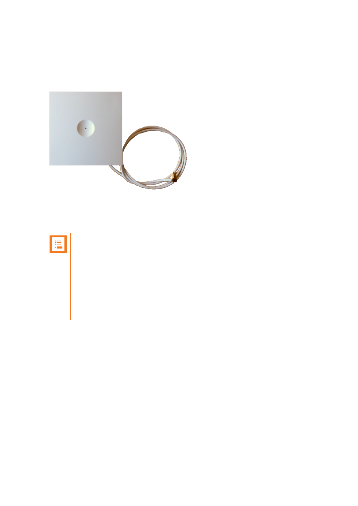
Description - External Antenna
Spectralink IP-DECT Base Stations, Spectralink IP-DECT Server 200/400 and Spectralink DECT
Repeaters can be equipped with an external antenna using a specially designed connection cable
between the external antenna and the host.
The external antenna is highly directional and used with Spectralink IP-DECT Base Stations or the
Spectralink IP-DECT Server 200/400 for added coverage in complex environments or to link up with
remote areas. External antennas can also be used with Spectralink DECT Repeaters to link up with
remote areas where wiring between the server and base station is difficult or impossible.
Note:
When used with a Spectralink IP-DECT Server 200/400 or Spectralink IP-DECT Base
Station, the external antenna always use the same channel as the host and provides full
coverage for handsets.
When used with a Spectralink DECT Repeater, the external antenna always use a channel different from the host and only provides a link to the main coverage area – no speech
coverage.
The range of the host (on base station and server) is reduced when the external antenna
is connected.
For more information about using the external antenna to add coverage in complex environments or
to link up with remote areas, see "Using the Spectralink IP-DECT Server 200/400 and Spectralink
IP-DECT Base Station With ExternalAntenna" on page78.
For more information about using the repeater with external antenna, see "Using the Spectralink
DECT Repeater With ExternalAntenna" on page76.
14215700-IG, Edition 8.0
April 2018, Originaldocument
23
Page 24
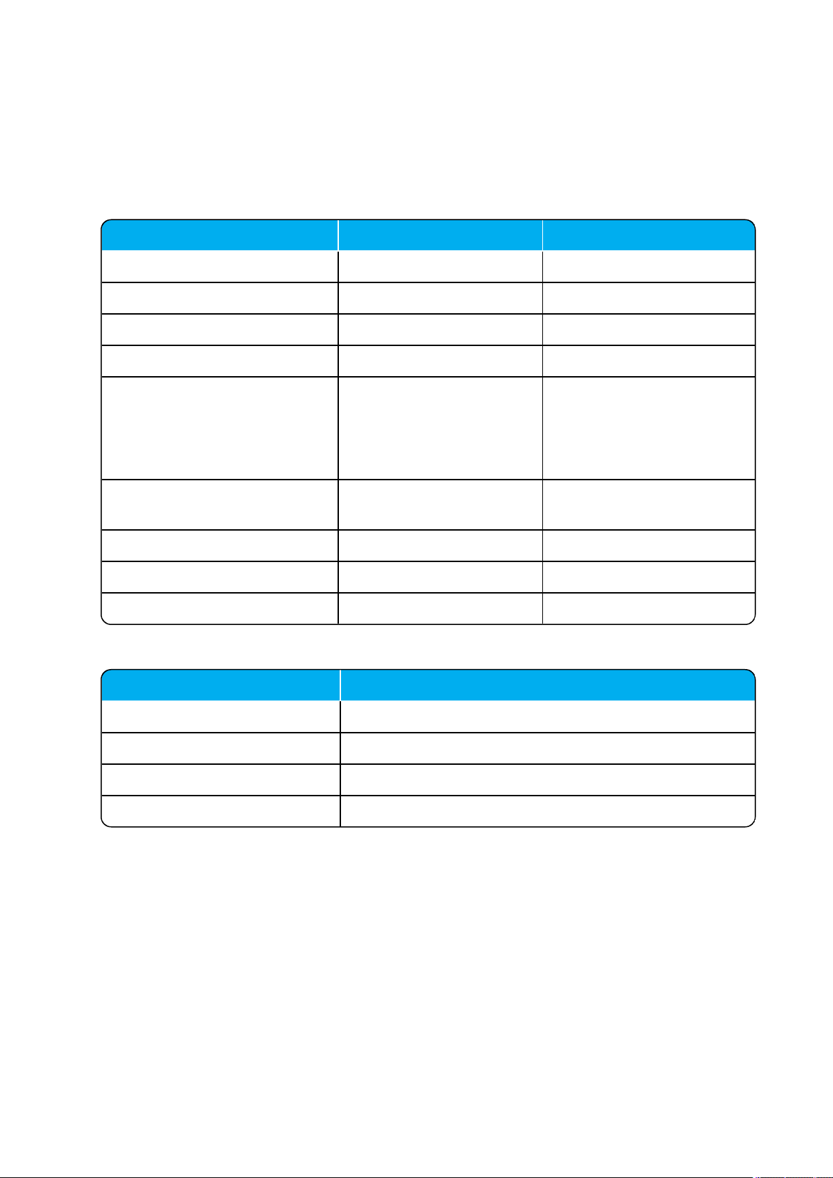
Description IP-DECT Server 400 IP-DECT Server 6500
IP-DECT Servers 1 1
Media Resources - 32
IP-DECT Base Stations - 1024
Protocol supported SIP SIP
Max number of simultaneous SIP
calls via license
12 1024
Up to 12 per Radio Base Station
32 per Media Resource
Codecs supported G.711a, G.711u, G.726,
G.729
G.711a, G.711u, G.726,
G.729
Wireless DECT handsets 30 4096
Max number of base stations 3 1024
Repeaters per base station 3 3
Item IP-DECT Server 6500 - Maximum Quantity
Media Resources 32
Protocol supported SIP
Simultaneous calls 32 (depending on used codec)*
Codecs supported G.711a, G.711u, G.726, G.729
SpectralinkIP-DECT Server 200/400/6500 Installation and Configuration Guide
System Capacity Overview
Below you will find an overview of the system capacity of the Spectralink IP-DECT Server:
System Capacity - Servers
System Capacity - Media Resources
* The available number of channels on a media resource depends on the codec type of the active
calls. Calls utilizing the G.726 codec uses approximately 2% of the available resources, calls utilizing
the G.711 codec uses approximately 3%, and calls utilizing the G.729 codec uses approximately 8%.
E.g.: With 5 active G.729 calls and 10 active G.711 calls, the total resource utilization will be approximately 70%.
14215700-IG, Edition 8.0
April 2018, Originaldocument
24
Page 25
SpectralinkIP-DECT Server 200/400/6500 Installation and Configuration Guide
Spectralink Server Solution Overview and Comparison
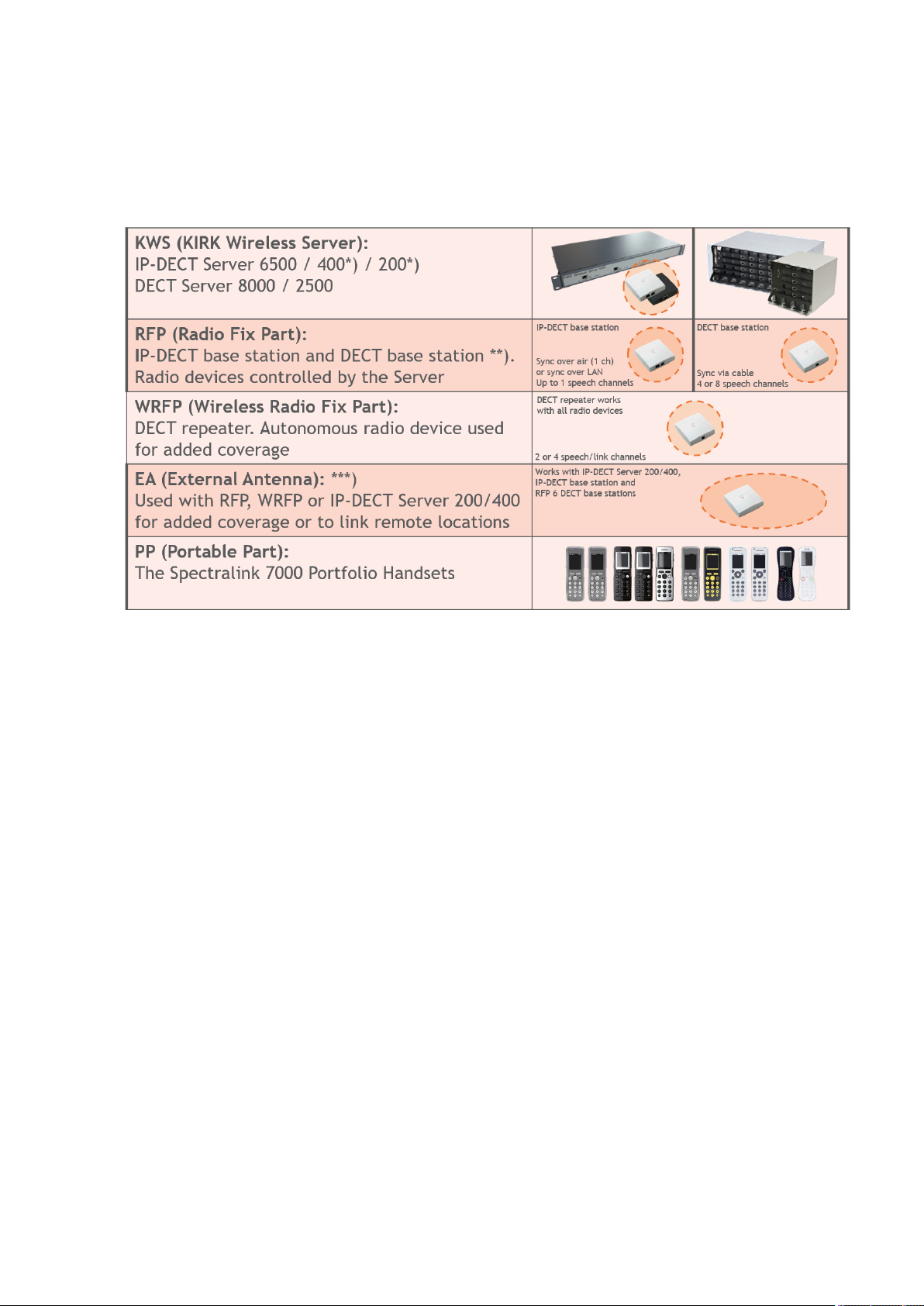
Product Overview
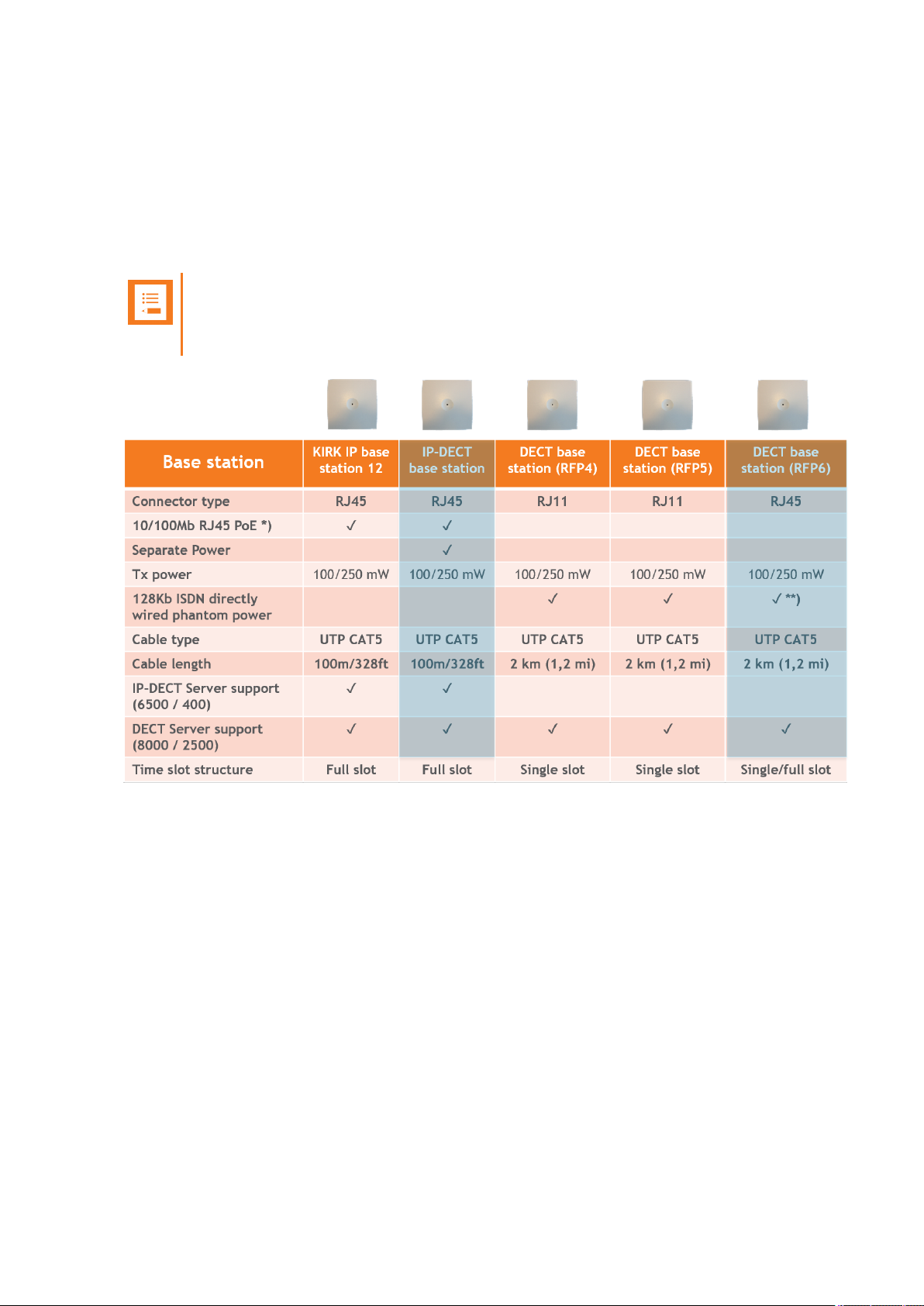
*) The Spectralink IP-DECT Server 200/400 has a built-in radio which acts like an Spectralink IPDECT Base Station with up to 12 speech channels.
**) Spectralink Digital DECT Base Stations are available in the following editions: RFP4 and RFP5
(4 speech channels) and RFP6 (4 or 8 speech channels).
***) The external antenna is highly directional and used with RFP6 Spectralink Digital DECT Base
Stations and Spectralink IP-DECT Base Stations or the Spectralink IP-DECT Server200/400 for
added coverage in complex environments or to link up with remote areas. External antennas can
also be used with Spectralink DECT Repeaters to link up with remote areas where wiring between
the server and base station is difficult or impossible.
For a comparison of Spectralink Servers, and Spectralink Base Stations, see "Server Comparison
Matrix" on page27 and "Base Station Comparison Matrix" on page29.
14215700-IG, Edition 8.0
April 2018, Originaldocument
25
Page 26
SpectralinkIP-DECT Server 200/400/6500 Installation and Configuration Guide
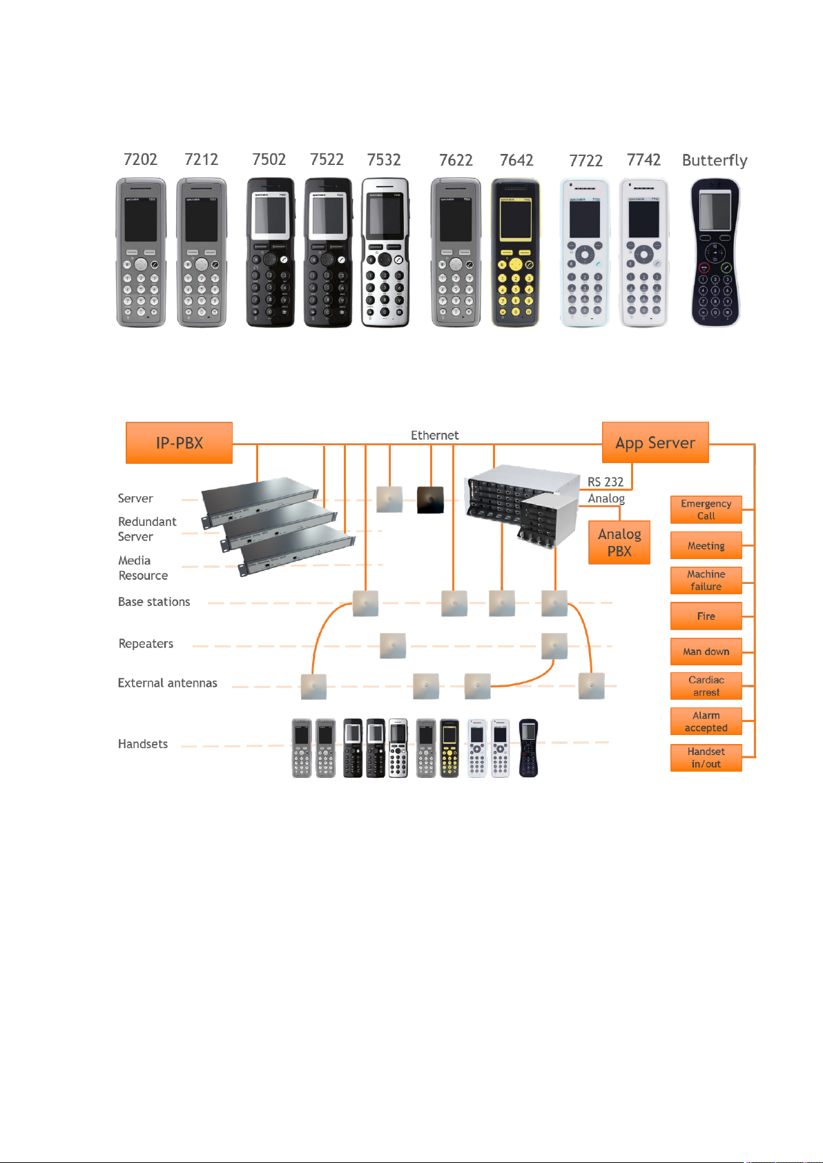
Spectralink Handset Portfolio Overview
For more information about the handsets, see the relevant Handset User Guides.
Total Configuration Overview
14215700-IG, Edition 8.0
April 2018, Originaldocument
26
Page 27
SpectralinkIP-DECT Server 200/400/6500 Installation and Configuration Guide
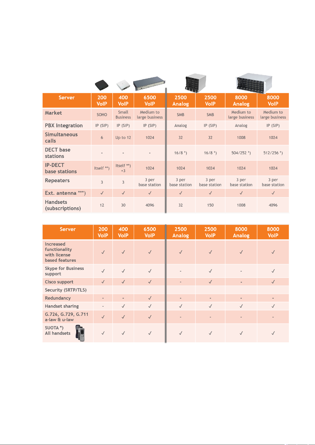
Server Comparison Matrix
The illustration below shows a Spectralink 7000 Portfolio Infrastructure/Spectralink Server comparison matrix.
*) 4 channel/8 channel Spectralink Digital DECT Base Station.
**) The Spectralink IP-DECT Server 200/400 has a built-in radio which acts like an Spectralink IPDECT Base Station with up to 12 speech channels.
14215700-IG, Edition 8.0
April 2018, Originaldocument
27
Page 28

SpectralinkIP-DECT Server 200/400/6500 Installation and Configuration Guide
***) External antenna can only be used with Spectralink IP-DECT Server 200/400, RFP 6 Spectralink Digital DECT Base Stations, Spectralink IP-DECT Base Stations and Spectralink DECT
Repeaters.
14215700-IG, Edition 8.0
April 2018, Originaldocument
28
Page 29
SpectralinkIP-DECT Server 200/400/6500 Installation and Configuration Guide
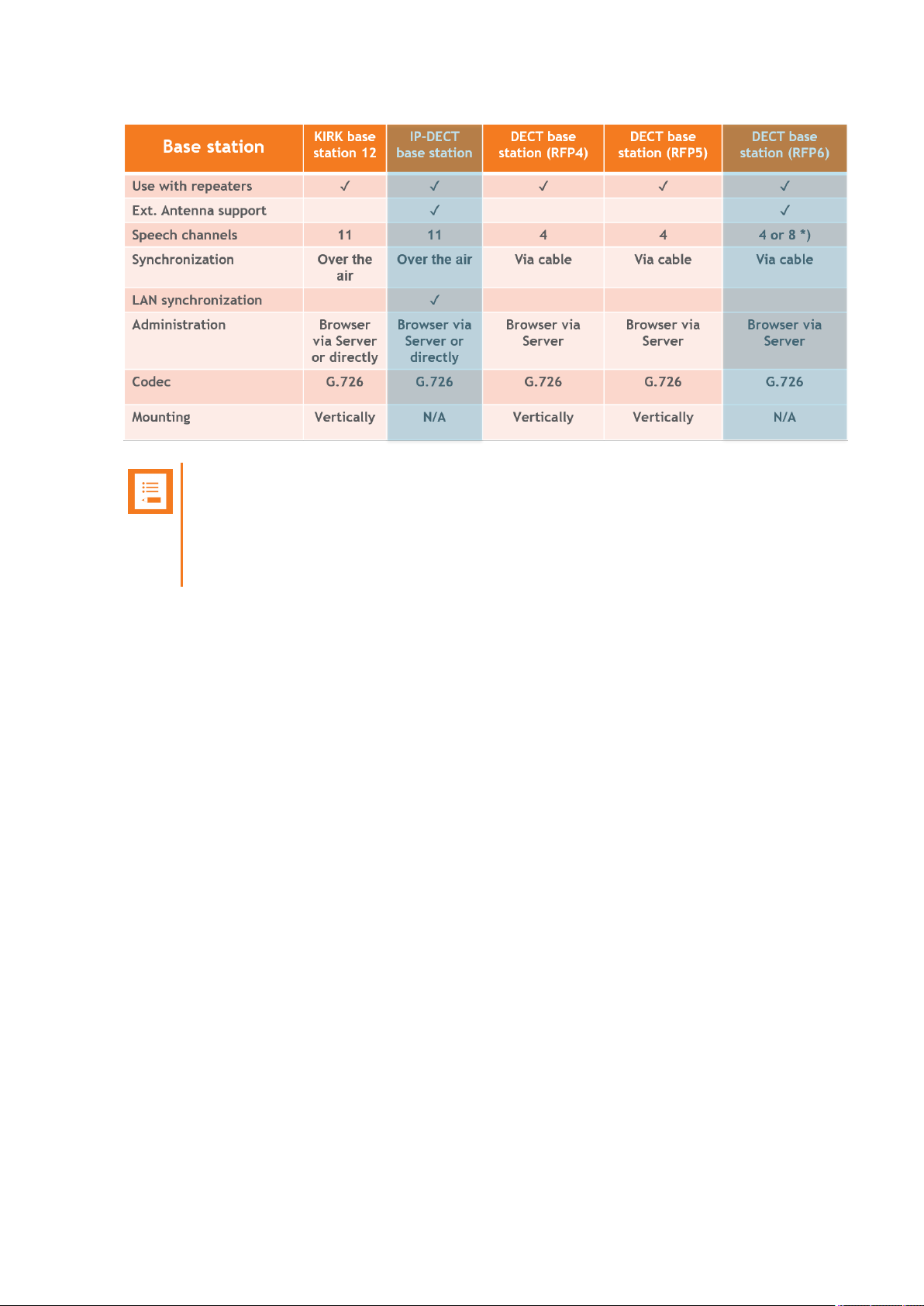
Base Station Comparison Matrix
The illustration below shows a Spectralink Base Station comparison matrix. In the comparison matrix you see the currently most used Spectralink base stations and the difference between them.
Only the Spectralink IP-DECT Base Station and the RFP6 Spectralink Digital DECT Base Station
are in production. All other base stations seen here are no longer in production, but are still widely
used in the field.
Note:
The Spectralink Digital DECT Base Stations are not relevant to the Spectralink IP-DECT
Servers.
14215700-IG, Edition 8.0
April 2018, Originaldocument
29
Page 30
SpectralinkIP-DECT Server 200/400/6500 Installation and Configuration Guide
Note:
It is possible to use LAN synchronization for Spectralink IP-DECT Base Station instead
of Radio synchronization (Over The Air). This requires installation of a LAN Synchronization License. For more information, see "LAN Based Synchronization (License
Required)" on page131.
14215700-IG, Edition 8.0
April 2018, Originaldocument
30
Page 31

SpectralinkIP-DECT Server 200/400/6500 Installation and Configuration Guide
Configuration Overview - Spectralink IP-DECT Server 200
The Spectralink IP-DECT Server 200 is typically configured as illustrated below:
The Spectralink IP-DECT Server 200 connects with Ethernet as well as the IP-PBX and 3rd party
application server.
Optional wireless repeaters can be used to extend the coverage of the Spectralink IP-DECT Server
200. External directional antennas are also optional and can be used with the Spectralink IP-DECT
Server 200 in physically complex environments which are challenging to cover with the built-in base
station or repeaters.
External antennas can also be used to create long distance coverage to bridge two locations belonging to the same DECT system. Spectralink DECT Repeaters can make use of external antennas as
well and create a link from a remote location to the main coverage area. There is no speech coverage in the linking area which is symbolized by the light blue color.
All Spectralink 7000 Handsets are supported. The Spectralink IP-DECT Server 200 itself connects
with the LAN via the ethernet interface, and an optional 3rd party application can communicate over
LAN with the Spectralink IP-DECT Server 200.
14215700-IG, Edition 8.0
April 2018, Originaldocument
31
Page 32

SpectralinkIP-DECT Server 200/400/6500 Installation and Configuration Guide
Configuration Overview - Spectralink IP-DECT Server 400
The Spectralink IP-DECT Server 400 is typically configured as illustrated below:
The Spectralink IP-DECT Server 400 connects with Ethernet as well as the IP-PBX and 3rd party
application server. The optional Spectralink IP-DECT Base Stations are controlled by the Spectralink IP-DECT Server 400.
Optional wireless repeaters can be used to extend the coverage of the Spectralink IP-DECT Base
Stations or the Spectralink IP-DECT Server 400 itself. External directional antennas are also
optional and can be used with Spectralink IP-DECT Base Stations or the Spectralink IP-DECT
Server 400 itself in physically complex environments which are challenging to cover with base stations or repeaters.
External antennas can also be used to create long distance coverage to bridge two locations belonging to the same DECT system. Spectralink DECT Repeaters can make use of external antennas as
well and create a link from a remote location to the main coverage area. There is no speech coverage in the linking area which is symbolized by the light blue color.
All Spectralink 7000 Handsets are supported.
14215700-IG, Edition 8.0
April 2018, Originaldocument
32
Page 33

SpectralinkIP-DECT Server 200/400/6500 Installation and Configuration Guide
Configuration Overview - Spectralink IP-DECT Server 6500
The Spectralink IP-DECT Server 6500 is typically configured as illustrated below:
The Spectralink IP-DECT Base Stations connect with the Ethernet as well as the IP-PBX and 3rd
party application server. The Spectralink IP-DECT Base Stations are controlled by the Spectralink
IP-DECT Server 6500.
Optional wireless Spectralink DECT Repeaters can be used to extend the coverage of the Spectralink IP-DECT Base Stations. External antennas are also optional and can be used with Spectralink IP-DECT Base Stations in physically complex environments which are challenging to cover
with base stations or repeaters.
External antennas can also be used to create long distance coverage to bridge two locations belonging to the same DECT system. Spectralink DECT Repeaters can make use of external antennas as
well and create a link from a remote location to the main coverage area. There is no speech coverage in the linking area which is symbolized by the light blue color.
All Spectralink 7000 Handsets are supported. The Spectralink IP-DECT Server 6500 itself connects
with the LAN via the ethernet interface and an optional 3rd party application can communicate over
LAN with the Spectralink IP-DECT Server 6500.
An optional Spectralink DECTMedia Resource and Redundancy Spectralink IP-DECT Server 6500
can be added to the network in order to increase speech resources or share system load and maximize uptime.
14215700-IG, Edition 8.0
April 2018, Originaldocument
33
Page 34

SpectralinkIP-DECT Server 200/400/6500 Installation and Configuration Guide
Communication Ports - Spectralink IP-DECT Server 200
The Spectralink IP-DECT Server utilizes a number of different protocols and ports on the network
(see illustration below).
These ports MUST not be blocked by firewalls or other network equipment.
Example of protocols and ports for a Spectralink IP-DECT Server 200:
*) Default configurable
**) If SIP per port registration is checked = 5060 + X (Number of SIP Registrations)
Spectralink IP-DECT Server 200 system can utilize the following protocols:HTTP/HTTPS,
FTP/TFTP, UPnP, MSF (TCP port 56003), syslog (UDP port 514), NTP, LDAP and SNMP.
Tip:
Use the communication port illustration as a reference when configuring your network for
a Spectralink IP-DECT Server 200 solution.
14215700-IG, Edition 8.0
April 2018, Originaldocument
34
Page 35

SpectralinkIP-DECT Server 200/400/6500 Installation and Configuration Guide
Communication Ports - Spectralink IP-DECT Server 400/6500
The Spectralink IP-DECT Server utilizes a number of different protocols and ports on the network
(see illustration below).
These ports MUST not be blocked by firewalls or other network equipment.
Example of protocols and ports for a Spectralink IP-DECT Server 6500:
*) Default configurable
**) If SIP per port registration is checked = 5060 + X (Number of SIP Registrations)
Spectralink IP-DECT Server 6500 system can utilize the following protocols:HTTP/HTTPS,
FTP/TFTP, UPnP, MSF (TCP port 56003), syslog (UDP port 514), NTP, LDAP and SNMP.
14215700-IG, Edition 8.0
April 2018, Originaldocument
35
Page 36

SpectralinkIP-DECT Server 200/400/6500 Installation and Configuration Guide
Example of protocols and ports for a Spectralink IP-DECT Server 400:
*) Default configurable
**) If SIP per port registration is checked = 5060 + X (Number of SIP Registrations)
Spectralink IP-DECT Server 400 system can utilize the following protocols:HTTP/HTTPS,
FTP/TFTP, UPnP, MSF (TCP port 56003), syslog (UDP port 514), NTP, LDAP and SNMP.
Tip:
Use the communication port illustration as a reference when configuring your network for
a Spectralink IP-DECT Server 400/6500 solution.
14215700-IG, Edition 8.0
April 2018, Originaldocument
36
Page 37

SpectralinkIP-DECT Server 200/400/6500 Installation and Configuration Guide
Service Codes - Spectralink IP-DECT Server
It is possible to access the Spectralink IP-DECT Server in operation using a handset.
Use any handset and enter ***999* followed by a 2-digit code for the information you wish to
retrieve, and then press off-hook.
Access basic information such as:
l IP address - enter ***999*00
l MAC addres - enter ***999*01
l Server firmware ***999*02
Note:
If UPnP is enabled, all Spectralink IP-DECT Servers can be identified on the network by
their serial number. For more information, see "Discovering the Spectralink IP-DECT
Components via UPnP" on page87.
The serial number can be found on the label on every Spectralink IP-DECT Server. For
more information, see "Identifying ARI on Spectralink IP-DECT Server" on page48.
14215700-IG, Edition 8.0
April 2018, Originaldocument
37
Page 38

SpectralinkIP-DECT Server 200/400/6500 Installation and Configuration Guide
Licenses
Licenses can be purchased to enable additional features on the Spectralink IP-DECT Server
200/400/6500. Some of the licenses are specific to the servers, some are common.
In the following you will find information about:
l Licenses for Spectralink IP-DECT Server 200
l Licenses for Spectralink IP-DECT Server 400/6500
For more information about obtaining and loading licenses, see "Ordering Licenses" on page43 and
"Loading Licenses" on page43.
Licenses for Spectralink IP-DECT Server 200
Licenses Description Server 200
Lync/SfB + Security (TLS, SRTP) |
IP-DECT Server 200
(1407 5511)
Security (TLS, SRTP) | IP-DECT
Server 200
(1407 5281)
Allows for integration with Microsoft
Skype for Business and additional
features.
Includes Software Security Package
(TLS + SRTP).
Enables SRTP (Secure Real-time
Transport Protocol) and TLS.
14215700-IG, Edition 8.0
April 2018, Originaldocument
38
Page 39

SpectralinkIP-DECT Server 200/400/6500 Installation and Configuration Guide
Licenses for Spectralink IP-DECT Server 400/6500
Licenses Description Server 400 Server 6500
12 Channels + 30 Users | IPDECT Server 400
(1407 5500)
12 Channels + 30 Users + Multicell | IP-DECT Server 400
(1407 5560)
Lync/SfB +Security (TLS,
SRTP) | IP-DECT Server 400
(1407 5510)
12 Channels + 30 Users + Lync/SfB + Security (TLS, SRTP) |
IP-DECT Server 400
(1407 5540)
Allows for up to 30 users and
up to 6 speech channels.
Increases the number of channels enabled from 6 to 12.
Allows:
Up to 30 users.
Up to 3 additional base stations.
Increases the number of channels enabled from 6 to 12.
Allows for up to 12 users and 6
speech channels.
Includes Software Security
Package (TLS + SRTP).
Allows:
Up to 30 users.
Increases the number of channels enabled from 6 to 12.
-
-
-
-
12 Channels + 30 Users + Lync/SfB + Security (TLS, SRTP)
+ Multicell | IP-DECT Server
400
(1407 5550)
Includes Software Security
Package (TLS + SRTP).
Allows:
Up to 30 users.
Up to 3 additional base stations.
-
Increases the number of channels enabled from 6 to 12.
Includes Software Security
Package (TLS + SRTP).
14215700-IG, Edition 8.0
April 2018, Originaldocument
39
Page 40

SpectralinkIP-DECT Server 200/400/6500 Installation and Configuration Guide
Licenses Description Server 400 Server 6500
Multicell | IP-DECT Server 400
(1407 5520)
LAN Sync | IP-DECT Server
400
(1407 5600)
Cisco Unified CM (Advanced
Features) | IP-DECT Server
400
(1407 5490)
Lync/SfB +Security (TLS,
SRTP) | IP-DECT Server
6000/6500
(1407 5270)
Allows:
Up to 12 users.
Up to 3 additional base stations.
Increases the number of channels enabled from 6 to 12.
Allows base stations to be synchronized over LAN.
Allows for tighter integration
with the Cisco Unified Communications Manager and additional features.
Allows for integration with
Microsoft Skype for Business
and additional features.
Includes Software Security
Package (TLS + SRTP).
-
-
-
-
LAN Sync | IP-DECT Server
6500
(1407 5610)
Security (TLS, SRTP) | IPDECT/DECT Servers
400/6000/6500/2500/8000
(1407 5280)
Handset Sharing License | IPDECT/DECT Servers
400/6500/2500/8000
(1407 5460)
Frequency Swap | IPDECT/DECT Servers
400/6500/2500/8000
(1407 5620)
Allows base stations to be synchronized over LAN.
Enables SRTP (Secure Realtime Transport Protocol) and
TLS.
Allows handsets to be shared
among numbers and vice
versa.
Allows the active radio frequency to be changed in
accordance to geographical
locations.
-
14215700-IG, Edition 8.0
April 2018, Originaldocument
40
Page 41

SpectralinkIP-DECT Server 200/400/6500 Installation and Configuration Guide
Licenses Description Server 400 Server 6500
Cisco Unified CM (Advanced
Features) | IP-DECT Server
6500
(1407 5495)
Automatic Alarm Call | IPDECT/DECT Servers
300/400/2500/6000/6500/8000
(1407 5450)
Redundancy Backup | IPDECT Server 6000/6500
(1407 5260)
Allows for tighter integration
with the Cisco Unified Communications Manager and additional features.
Allows the use of alarm key,
with tear-off and/or motion
sensors.
The Automatic Alarm Call
license can trigger an alarm.
There are 4 alarm triggers
available depending on the
type of Spectralink DECT
Handset being used:
l man down
l running
l tear-off
l alarm button
Allows adding a backup server
to a system.
-
-
Redundancy Master | IP-DECT
Server 6000/6500
(1407 5250)
30 Users | IP-DECT Server
6000/6500
(1407 5200)
150 Users | IP-DECT Server
6000/6500
(1407 5210)
500 Users | IP-DECT Server
6000/6500
(1407 5220)
1500 Users | IP-DECT Server
6000/6500
(1407 5230)
Allows adding a backup server
to a system.
Allows for up to 30 users.
Allows for up to 150 users.
Allows for up to 500 users.
Allows for up to 1500 users.
-
-
-
-
-
14215700-IG, Edition 8.0
April 2018, Originaldocument
41
Page 42

SpectralinkIP-DECT Server 200/400/6500 Installation and Configuration Guide
Licenses Description Server 400 Server 6500
4096 Users | IP-DECT Server
6000/6500
(1407 5240)
Lync/SfB +Security (TLS,
SRTP) | IP-DECT Server
6000/6500
(1407 5270)
Enhanced Provisioning Interface | IP-DECT Server 400
(1407 5701)
Enhanced Provisioning Interface | IP-DECT Server 6500
(1407 5200)
Allows for up to 4096 users.
Allows for integration with
Microsoft Skype for Business
and additional features.
Includes Software Security
Package (TLS + SRTP).
Allows for provisioning of firmware for:
l IP-DECT base stations
l Handsets
Allows for provisioning of firmware for:
l IP-DECT base stations
l Media resources
l Handsets
-
-
-
-
Additional repeaters (up to 6
repeaters) | IP-DECT Server
400
1407 5570
Allows for use of up to 6 additional repeaters.
-
14215700-IG, Edition 8.0
April 2018, Originaldocument
42
Page 43

SpectralinkIP-DECT Server 200/400/6500 Installation and Configuration Guide
Ordering Licenses
1. Send your Purchase Order (PO) including the software part number and the number of
licenses needed to Spectralink Order Management via (EMEA and APAC) emeaom@spec-
tralink.com or (NALA) nalaom@spectralink.com .
2. When your order is processed, Order Management will send you an email including an
Authentication Product Key for your software license.
3. To activate your software license, use the License Key Generator available at http://sup-
port.spectralink.com/keycode .
Note:
Once a software license is generated, this is locked to the specified ARI code, and cannot
be changed.
Loading Licenses
1. Click Administration, and then click License.
2. Copy the provided license key from your email, paste it in the License field, and then click
Load.
3. Reboot the server to activate the license.
Loaded licenses can be seen on the web based Administration Page > Administration > Licenses
> Loaded licenses.
For information about deleting a license and retrieving a license being deleted by mistake, see "Delet-
ing Licenses" on page172.
14215700-IG, Edition 8.0
April 2018, Originaldocument
43
Page 44

SpectralinkIP-DECT Server 200/400/6500 Installation and Configuration Guide
Installation Requirements
Safety and Handling information is available online at http://support.spectralink.com/products.
All Spectralink documents are available at http://support.spectralink.com/products.
Requirements for Spectralink IP-DECT Server 200/400
The Spectralink IP-DECT Server 200/400 is a combined Spectralink IP-DECT Base Station and
server.
For more information about requirements, see "Requirements for Spectralink IP-DECT Base Sta-
tion and Spectralink DECT Repeater" on the next page.
Requirements for Spectralink IP-DECT Server 6500
and Spectralink DECTMedia Resource
Environmental Requirements
The installation area must:
l be clean, free of traffic and excess dust, dry, and well ventilated
l be within the temperature ranges of 10°C and 40°C/50°F and 104°F
l be between 20% and 80% non-condensing relative humidity
Note:
The installation area must be of sufficient height from the floor to prevent water damage.
1U rack space in a 19" cabinet or respective space on the wall when mounting the Spectralink IP-DECT Server 6500 in vertical position on a wall.
For more information about installing the Spectralink IP-DECT Server and Spectralink DECTMedia
Resource, see "Installing the Spectralink IP-DECT Server 6500 and Spectralink DECTMedia
Resource" on page55.
14215700-IG, Edition 8.0
April 2018, Originaldocument
44
Page 45

SpectralinkIP-DECT Server 200/400/6500 Installation and Configuration Guide
Requirements for Spectralink IP-DECT Base Station and Spectralink DECT Repeater
Note:
The Spectralink IP-DECT Server 200/400 is a combined Spectralink IP-DECT Base Station and server. Therefore, the below mentioned requirements also applies to the Spectralink IP-DECT Server 200/400.
Environmental Requirements
l Do not install a device near metal objects and steel constructions.
l Do not position devices in ducts, plenums or hollow spaces used to transport environmentalair
except where the duct, plenum or hollow space is created by a suspended ceiling having lay-in
panels.
l Do not position devices behind furniture.
l The installation area must be clean, free of traffic and excess dust, dry, and well ventilated.
l The installation area must be within the temperature ranges of 10°C and 40°C/50°F and
104°F.
l The installation area must be between 20% and 80% non-condensing relative humidity.
l For best RF coverage, the device must be mounted vertically on walls.
PowerRequirements
The Spectralink IP-DECT Base Station uses:
l Power over Ethernet (PoE 802.3af).
l Maximum power supply consumption is 3.0W (IEEE 802.3af class 1 device).
Use a standard PoE adapter or a PoE-enabled port on a switch adhering to PoE 802.3af when connecting the base station to a PoE power source.
Use an 8V-DC power supply when using a port without PoE.
For more information about installing the Spectralink IP-DECT Base Station and Spectralink DECT
Repeater, see "Installing the Spectralink IP-DECT Base Station" on page62 and "Installing the
Spectralink DECT Repeater" on page68.
Note:
For more information about installing the Spectralink IP-DECT Server 200, see
"Installing the Spectralink IP-DECT Server 200" on page49.
For more information about installing the Spectralink IP-DECT Server 400, see
"Installing the Spectralink IP-DECT Server 400" on page54 and "Installing the Spectralink IP-DECT Base Station" on page62.
14215700-IG, Edition 8.0
April 2018, Originaldocument
45
Page 46

SpectralinkIP-DECT Server 200/400/6500 Installation and Configuration Guide
Requirements for Spectralink DECT Handset
For more information about the handset, refer to the user guide available online at http://sup-
port.spectralink.com/products.
Requirements for Spectralink Maintenance Software
Software Requirements
The following is required to run the handset and repeater installation and maintenance tools.
l OS: Windows 7 or newer
14215700-IG, Edition 8.0
April 2018, Originaldocument
46
Page 47

SpectralinkIP-DECT Server 200/400/6500 Installation and Configuration Guide
Installation Prerequisites
Note:
Ensure that a site survey and deployment have been conducted and that the installer has
access to these plans before proceeding any further. For more information about deployment, see the Synchronization and Deployment Guide for the Spectralink IP-DECT
Server 400/6500 or theIP-DECT Server 200 Deployment and Installation Configuration
Guidedepending on your installation.
Before you start the installation, you need to find the following information and perform the following
tasks:
l ARI for the Spectralink IP-DECT Server (see label on the rear of the server unit)
For more information, see "Identifying ARI on Spectralink IP-DECT Server" on the next page.
l Serial numbers for handsets.
For more information, see "Identifying IPEI on Spectralink Handset" on the next page.
l AC (Authentication Codes)
The AC is a customer-defined optional subscription pin code of a maximum of eight digits for
the individual handset. The AC can be used when connecting the handset to the server.
l Repeaters:
Mark each repeater with the number of the related base station (or Spectralink IP-DECT
Server 200/400). This way you can easily configure the system on site.
l Handsets:
To use the handsets, you must first install the radio infrastructure, e.g. base stations and
repeaters to transmit and receive radio signals to and from the handsets. There are no direct
connections between the handset and the system.
l Charging battery
When charging the handset battery for the first time, leave the handset in the charger for 14 16 hours to ensure that the battery is fully charged and the handset ready for use. For more
information about the handset, refer to the user guide available online at http://sup-
port.spectralink.com/products.
14215700-IG, Edition 8.0
April 2018, Originaldocument
47
Page 48

SpectralinkIP-DECT Server 200/400/6500 Installation and Configuration Guide
About ARI and IPEI Identification
All Spectralink DECT Handsets and all Spectralink IP-DECT Servers have unique identification numbers.
This is needed in order for:
l The handsets to know which Spectralink IP-DECT Server installation they belong to.
l The Spectralink IP-DECT Server to know which handsets that are subscribed to it.
A handset uses an International Portable Equipment Identifier, also called IPEI number, for handset
identification and subscription to a Spectralink IP-DECT Server.
A Spectralink IP-DECT Server uses an Access Right Identity number, also called ARI number, for
server identification.
When an IPEI number of a handset is linked to a Spectralink IP-DECT Server, the handset is subscribed. There is a record in the Spectralink IP-DECT Server holding information about all the handsets being subscribed to it. This record is subdivided in to User profiles, often referred to as just a
User. Each User must hold information about extension number, the handset’s IPEI number, and its
registration credentials for the PBX. This information is used to link the subscribed handset to the
PBX which is the same as a line registration. A Users profile holds subscription data and registration
data. For more information, see "Registering Users and Subscribing Spectralink DECT Handsets"
on page139.
Identifying IPEI on Spectralink Handset
You can identify the unique IPEI number on a handset in two ways:
l From the handset: Menu > Status > General
l From label by removing the battery cover and battery
For more information about the handset, refer to the user guide available online at http://sup-
port.spectralink.com/products.
Identifying ARI on Spectralink IP-DECT Server
You can identify the unique ARI number on the server in the following ways:
l Spectralink IP-DECT Server 6500: See label on the bottom of the server.
l Spectralink IP-DECT Server 200/400: See label on the rear side of the server.
l Spectralink IP-DECT Server 200/400/6500: From the web based Administration Page >
Status > Wireless Server.
14215700-IG, Edition 8.0
April 2018, Originaldocument
48
Page 49

SpectralinkIP-DECT Server 200/400/6500 Installation and Configuration Guide
Installing the Spectralink IP-DECT Server 200
Below you will find information about installing the server.
Note:
Before you install the equipment, ensure that a site planner defines the location of the
server.
Before you begin the installation, determine the position of the server for best coverage.
The average coverage within buildings is 75 meters/245 feet.
The coverage depends on the construction of the building, architecture, and the choice of
building materials.
Power Requirements for the Spectralink IP-DECT Server 200
l Power over Ethernet (PoE 802.3af).
l Maximum power supply consumption is 3.0W (IEEE 802.3af class 1 device).
Use a standard PoE adapter or a PoE-enabled port on an ethernet switch adhering to PoE 802.3af
when connecting the Spectralink IP-DECT Server 200 to a PoE power source.
Use an 8V-DC power supply when using a port without PoE.
14215700-IG, Edition 8.0
April 2018, Originaldocument
49
Page 50

Spectralink IP-DECT Server 200 - bottom Spectralink IP-DECT Server 200 - rear
1. Resetbutton
2. DC
3. LINK/ActivityIndicator
4. ETH port (power supply by PoE)
1. Holesfor wallmountedscrews
2. Connection to LAN
SpectralinkIP-DECT Server 200/400/6500 Installation and Configuration Guide
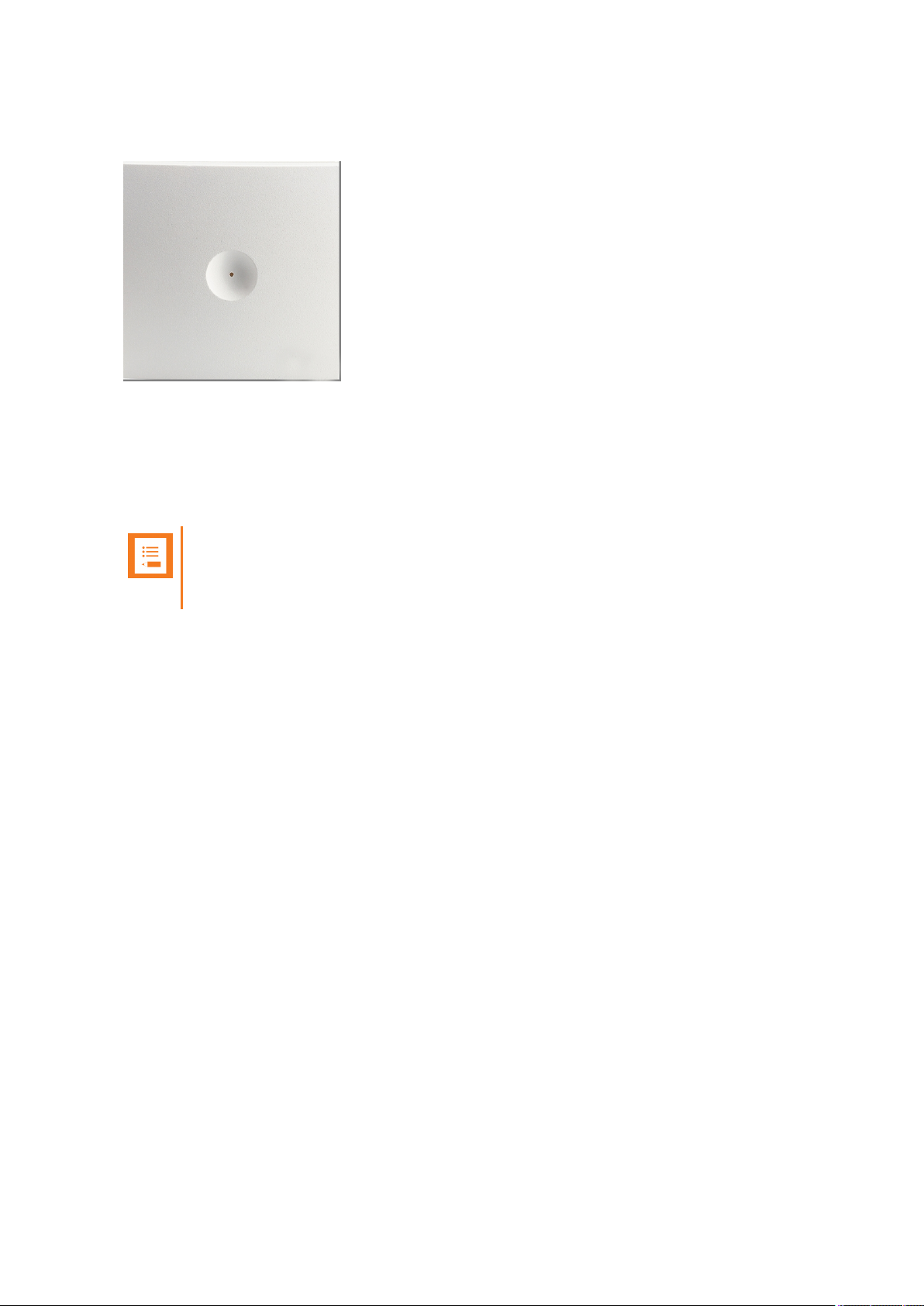
Spectralink IP-DECT Server 200 Appearance and Components
Below you will find a description of the Spectralink IP-DECT Server 200 appearance and components:
14215700-IG, Edition 8.0
April 2018, Originaldocument
50
Page 51

Spectralink IP-DECT Server 200 - front
1. LED
LED Indicator Meaning
Steady green OK and idle.
Slow green flashing OK and active voice call.
Fast green flashing Busy (all channels are in use).
Steady red Reset/shutdown in progress.
Steady red for 5 seconds followed by
fast red flashing
Reset to factory settings.
Red flashing Error or rebooting
SpectralinkIP-DECT Server 200/400/6500 Installation and Configuration Guide
Spectralink IP-DECT Server 200 LED Indicators
Below you will find information about LED indicators on the server.
Front Cover
The server front cover has one indicator describing the server faults and failures. The indicator is off
when the server is not powered. The LED flashes when the server initializes. The indicator is on
when the server is operating.
14215700-IG, Edition 8.0
April 2018, Originaldocument
51
Page 52

LED Indicator Meaning
LINK Indicator - yellow Link layer software has established connection.
LINK Indicator - green flashing Activity
Press button Action
Short press (2 to 5 sec.) System restarts when button is released.
Long press (5 to 9 sec.) until front LED
flashes red, then release button
Resets the system to factory default settings (original IP
settings - DHCP) and restarts the system. Firmware version is not affected.
SpectralinkIP-DECT Server 200/400/6500 Installation and Configuration Guide
LAN Port on Face Plate
Spectralink IP-DECT Server 200 Reset Button
You can restart or reset the Spectralink IP-DECT Server 200 by pressing the Reset button on the
bottom of face plate of the server.
The following table contains a description of the different actions that take place when pressing the
Reset button.
Wall-Mount and Power on the Spectralink IP-DECT Server 200
For best RF coverage, the Spectralink IP-DECT Server 200 must be mounted vertically on walls.
1. Mount the Spectralink IP-DECT Server 200 on the wall using the anchors and screws accompanying the product.
Note:
When you place the Spectralink IP-DECT Server 200 on the screws, ensure that
the screws do not touch the printed circuit board.
14215700-IG, Edition 8.0
April 2018, Originaldocument
52
Page 53

SpectralinkIP-DECT Server 200/400/6500 Installation and Configuration Guide
1. Holesfor wallmountedscrews
2. RJ45 port
2. Connect the RJ45 plug to the ethernet connector at the bottom of the Spectralink IP-DECT
Server 200.
3. After installing the Spectralink IP-DECT Server 200 you need to power it up.
14215700-IG, Edition 8.0
April 2018, Originaldocument
53
Page 54

SpectralinkIP-DECT Server 200/400/6500 Installation and Configuration Guide
Installing the Spectralink IP-DECT Server 400
The Spectralink IP-DECT Server 400 is a combined Spectralink IP-DECT Base Station and server.
For more information about appearance and components, Reset Button and mounting, see
"Installing the Spectralink IP-DECT Base Station" on page62.
Note:
Before you install the equipment, ensure that a site planner defines the locations of the
server.
14215700-IG, Edition 8.0
April 2018, Originaldocument
54
Page 55

SpectralinkIP-DECT Server 200/400/6500 Installation and Configuration Guide
Installing the Spectralink IP-DECT Server
6500 and Spectralink DECTMedia
Resource
This section describes the appearance and components of the:
l Spectralink IP-DECT Server 6500/Spectralink DECTMedia Resource
The section also provides information about resetting the Spectralink IP-DECT Server/Spectralink
DECTMedia Resource hardware using the Reset button.
Note:
The installation of a Spectralink DECTMedia Resource with the Spectralink IP-DECT
Server 6500 is optional. Installation of a media resource will increase the number of simultaneous voice calls supported by a stand-alone server.
The Spectralink IP-DECT Server 6500 comes with one built-in media resource.
Before you install the equipment, ensure that a site planner defines the locations of the Spectralink
IP-DECT Server 6500 and Spectralink DECTMedia Resources.
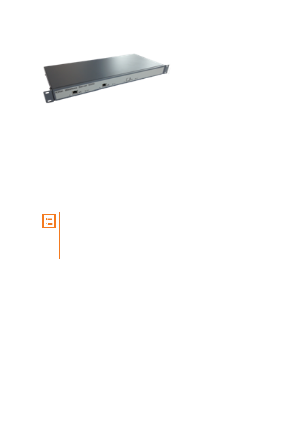
Server Appearance and Components
Below you will find a description of the Spectralink IP-DECT Server 6500 appearance and components:
14215700-IG, Edition 8.0
April 2018, Originaldocument
55
Page 56

LED Indicator Meaning
Steady green OK and idle.
Slow green flashing OK and active voice call.
Fast green flashing Active, in operation with the maximum active connections (busy).
Slow red flashing Missing media resource or base station (if it is a media resource:
missing connection to Spectralink IP-DECT Server 6500).
Fast red flashing Error
Steady red Reset/shutdown in progress.
Steady red for 5 seconds followed by fast red flashing
Reset to factory settings.
LED Indicator Meaning
LINK Indicator - yellow Link layer software has established connection.
Activity Indicator - green flashing Activity
SpectralinkIP-DECT Server 200/400/6500 Installation and Configuration Guide
Server and Media Resource LED Indicators
Below you will find information about LED indicators on the Spectralink IP-DECT Server 6500 and
Spectralink DECTMedia Resource.
Front Faceplate
The Spectralink IP-DECT Server 6500/Spectralink DECTMedia Resource front cover has one indicator describing the faults and failures of the device. The indicator is off when the Spectralink IPDECT Server 6500/Spectralink DECTMedia Resource is not powered. The LED flashes when the
Spectralink IP-DECT Server 6500/Spectralink DECTMedia Resource initializes. The indicator is on
when the Spectralink IP-DECT Server 6500/Spectralink DECTMedia Resource is operating.
Front LAN Port
14215700-IG, Edition 8.0
April 2018, Originaldocument
56
Page 57

Press button Action
Short press (2 to 5 sec.) System restarts when button is released.
Long press (5 to 9 sec.) until
front LED flashes red, then
release button
Resets the system to factory default settings (original IP settings
and empty user data base) and restarts the system. Firmware version is not affected.
SpectralinkIP-DECT Server 200/400/6500 Installation and Configuration Guide
Server and Media Resource Reset Button
You can restart or reset the Spectralink IP-DECT Server 6500/Spectralink DECTMedia Resource
by pressing the Reset button on the front of the server/media resource.
Resetting or Restarting the Spectralink IP-DECT Server and Spectralink
DECTMedia Resource
Below you will find information about Reset button actions that can take place when you press the
Reset button.
Mounting in aRack
The Spectralink IP-DECT Server 6500/Spectralink DECTMedia Resource is mountable in a rack.
1. Mount the two wings with the screws. If you are mounting the Spectralink IP-DECT Server
6500 on a wall, twist the wings 90° degrees.
2. Mount the cabinet in the 19" rack or on the wall.
Note:
Screws and nuts/rawl plugs are not supplied.
3. Connect the RJ45 ethernet plug to the front of the cabinet.
All Spectralink IP-DECT Server 6500s and Spectralink DECTMedia Resources must be connected to a switch port.
Installed Spectralink DECTMedia Resources must have their own switchport.
4. Connect the power on the back of the cabinet.
14215700-IG, Edition 8.0
April 2018, Originaldocument
57
Page 58

SpectralinkIP-DECT Server 200/400/6500 Installation and Configuration Guide
Adding Aditional Spectralink DECTMedia Resources
The Spectralink IP-DECT Server 6500 can be upgraded with up to two additional Spectralink
DECTMedia Resources to increase speech capacity. Each Spectralink DECTMedia Resource
provides 32 speech channels and is purchased seperately.
Below is an image of the Spectralink IP-DECT Server 6500 cabinet. The Spectralink IP-DECT
Server 6500 itself resides to the far left, which is standard, and the two optional Spectralink
DECTMedia Resources reside in the middle and to the far right.
Note:
It is possible to have cabinets with Spectralink DECTMedia Resources only, but they can
only be used in conjunction with a Spectralink IP-DECT Server 6500.
14215700-IG, Edition 8.0
April 2018, Originaldocument
58
Page 59

SpectralinkIP-DECT Server 200/400/6500 Installation and Configuration Guide
How to Add a Spectralink DECTMedia Resource
1. Remove the top cover from the cabinet.
2. Unpack the media resource board.
3. Cut a hole for the RJ45 network connector in the front foil of the cabinet.
4. Mount the media resource board in the cabinet with three screws.
14215700-IG, Edition 8.0
April 2018, Originaldocument
59
Page 60

SpectralinkIP-DECT Server 200/400/6500 Installation and Configuration Guide
5. Prepare the media resource power connector.
6. Connect the power cable to the media resource power connector.
14215700-IG, Edition 8.0
April 2018, Originaldocument
60
Page 61

SpectralinkIP-DECT Server 200/400/6500 Installation and Configuration Guide
7. Close the cabinet again.
14215700-IG, Edition 8.0
April 2018, Originaldocument
61
Page 62

SpectralinkIP-DECT Server 200/400/6500 Installation and Configuration Guide
Installing the Spectralink IP-DECT Base Station
Below you will find information about installing the base station.
Note:
Before you install the equipment, ensure that a site planner defines the location of the
base stations.
Before you begin the installation, determine the position of the base station for best coverage. The average coverage within buildings is 75 meters/245 feet.
The coverage depends on the construction of the building, architecture, and the choice of
building materials.
Power Requirements for the Base Station
The Spectralink IP-DECT Base Station uses:
l Power over Ethernet (PoE 802.3af).
l Maximum power supply consumption is 3.0W (IEEE 802.3af class 1 device).
Use a standard PoE adapter or a PoE-enabled port on a switch adhering to PoE 802.3af when connecting the base station to a PoE power source.
Use an 8V-DC power supply when using a port without PoE.
14215700-IG, Edition 8.0
April 2018, Originaldocument
62
Page 63

Spectralink IP-DECT Base Station - rear
1. Holesfor wallmountedscrews
2. Connection to LAN
IP-DECT Base Station - front
1. LED
SpectralinkIP-DECT Server 200/400/6500 Installation and Configuration Guide
Base Station Appearance and Components
Below you will find a description of the base station appearance and components:
14215700-IG, Edition 8.0
April 2018, Originaldocument
63
Page 64

IP-DECT Base Station
1. Resetbutton
2. DC
3. LINK/ActivityIndicator
4. ETH port (power supply by PoE)
SpectralinkIP-DECT Server 200/400/6500 Installation and Configuration Guide
14215700-IG, Edition 8.0
April 2018, Originaldocument
64
Page 65

LED Indicator Meaning
Steady green OK and idle.
Slow green flashing OK and active voice call.
Fast green flashing Busy (all channels are in use).
Slow red flashing No server connection.
Fast red flashing No sync over air possible, or sync master is not avail-
able, or other error.
Steady red Reset/shutdown in progress.
Steady red for 5 seconds followed by
fast red flashing
Reset to factory settings.
LED Indicator Meaning
LINK Indicator - yellow Link layer software has established connection.
LINK Indicator - green flashing Activity
Press button Action
Short press (2 to 5 sec.) System restarts when button is released.
Long press (5 to 9 sec.) until front LED
flashes red, then release button
Resets the system to factory default settings (original IP
settings - DHCP) and restarts the system. Firmware version is not affected.
SpectralinkIP-DECT Server 200/400/6500 Installation and Configuration Guide
Base Station LED Indicators
Below you will find information about LED indicators on the base station.
Front Cover
The base station front cover has one indicator describing the base station faults and failures. The
indicator is off when the base station is not powered. The LED flashes when the base station initializes. The indicator is on when the base station is operating.
LAN Port on Face Plate
Base Station Reset Button
You can restart or reset the base station by pressing the Reset button on the bottom of face plate of
the base station.
The following table contains a description of the different actions that take place when pressing the
Reset button.
14215700-IG, Edition 8.0
April 2018, Originaldocument
65
Page 66

SpectralinkIP-DECT Server 200/400/6500 Installation and Configuration Guide
Mounting the Base Station
The base station is suitable for mounting indoors on a wall.
The base stations are designed to only be mounted on the wall at least 2,40 m (8ft) off the ground but
no higher than 6 m (20ft). The connectors can be pointed either up or down. The base stations
should not be flush mounted to the ceiling as it would affect signal propagation. If ceiling mounting is
a requirement, the base stations could be drop mounted from the ceiling in the same orientation (i.e.,
vertical) and height (no higher than 6 m (20ft) from ground as described for wall mounting. If mounting base stations higher than 6 m (20ft) off the ground, coverage directly underneath the base station
will be impacted.
Wall Mounted (Vertical) Installation RF Coverage
For best RF coverage, the base station must be mounted vertically on walls. The antennas must
always be kept perpendicular to the floor.
Caution:
l The base station must not be installed at any angle other than vertical.
l Do not mount the base station on soft surfaced walls such as those covered with
canvas, metal or sponge-like materials.
How to Wall Mount the Spectralink IP-DECT Base Station
The base station must be mounted vertically on the wall for best coverage.
1. Use a twisted pair cable, cat. 5e or higher between the base station and the network switch.
2. Mount the base station onto the wall using the screws accompanying the base station.
Note:
When you place the base station on the screws, ensure that the screws do not
touch the printed circuit board.
14215700-IG, Edition 8.0
April 2018, Originaldocument
66
Page 67

SpectralinkIP-DECT Server 200/400/6500 Installation and Configuration Guide
1. Holesfor wallmountedscrews
2. RJ45 port
3. Connect the network cable to the RJ45 port.
4. After installing the base station you need to power it up. For more information, see "Power
Requirements for the Base Station" on page62.
14215700-IG, Edition 8.0
April 2018, Originaldocument
67
Page 68

SpectralinkIP-DECT Server 200/400/6500 Installation and Configuration Guide
Installing the Spectralink DECT Repeater
This section describes the Spectralink DECT Repeater and how to unpack and install it. Installing
repeaters requires a software installation as well as a hardware installation.
Note:
Before you install the equipment, ensure that a site planner defines the location of the
repeaters.
The coverage depends on the construction of the building and the choice of building
materials.
The repeater does not add channels. It only adds additional coverage area.
For installations, the following items should be present in every box containing a Spectralink DECT
Repeater:
l Spectralink DECT Repeater
l Mounting template
l Two mounting screws and anchors
14215700-IG, Edition 8.0
April 2018, Originaldocument
68
Page 69

DECT Repeater - bottom DECT Repeater - rear
1. RJ9 port 1. Holesfor wallmountedscrews
2. Externalantenna connector
DECT Repeater - front
1. LED
SpectralinkIP-DECT Server 200/400/6500 Installation and Configuration Guide
Repeater Appearance and Components
Below you will find a description of the repeater appearance and components:
14215700-IG, Edition 8.0
April 2018, Originaldocument
69
Page 70

LED Indicator Meaning
Indicator Off The repeater is not powered.
Flashing Repeater has been powered, sync has still not been
established.
Steady green The repeater is powered and sync is established.
Short flash A handset connects or makes handover to the repeater.
SpectralinkIP-DECT Server 200/400/6500 Installation and Configuration Guide
Repeater LED Indicators
Below you will find information about LED indicators on the repeater.
Front Cover
Site Installation Considerations
Before you begin the installation, determine the position of the repeater for best coverage. The coverage depends on the construction of the building and the choice of building materials.
The repeater can be registered on the system under the following circumstances.
l When placed within the coverage area of a base station/server 200/400
l When placed within the coverage area of an already-installed repeater
l When placed outside the coverage area of a base station or repeater using an external
antenna.
Note:
The repeater does not add channels. It only adds additional coverage area.
Environmental Considerations
l Do not install a device near metal objects and steel constructions.
l Do not position devices in ducts, plenums or hollow spaces used to transport environmentalair
except where the duct, plenum or hollow space is created by a suspended ceiling having lay-in
panels.
l Do not position devices behind furniture.
l The installation area must be clean, free of traffic and excess dust, dry, and well ventilated.
l The installation area must be within the temperature ranges of 10°C and 40°C/50°F and
104°F.
l The installation area must be between 20% and 80% non-condensing relative humidity.
l For best RF coverage, the device must be mounted vertically on walls.
14215700-IG, Edition 8.0
April 2018, Originaldocument
70
Page 71

SpectralinkIP-DECT Server 200/400/6500 Installation and Configuration Guide
How to Wall Mount the Repeater
For best RF coverage, the device must be mounted vertically on walls.
Caution:
The repeater and external antenna is to be fixed-mounted on indoor permanent structures providing a separation distance of at least 20 cm/8 inches from all persons during
normal operation and must not be co-located or operating in conjunction with any other
antenna or repeater. The maximum radiated output power is 1W e.i.r.p.
1. Connect the power supply cable to the RJ9 port on the bottom of the repeater.
For repeaters with external antenna, connect the external antenna cable to the antenna connector on the rear side of the repeater and in the same way on the external antenna.
2. Mount the repeater on the wall using the anchors and screws accompanying the product.
3. After installing the repeater you need to power it up. The power supply for the repeater is
9VDC, 350mA.
14215700-IG, Edition 8.0
April 2018, Originaldocument
71
Page 72

SpectralinkIP-DECT Server 200/400/6500 Installation and Configuration Guide
Programming a Spectralink DECT Repeater with the Repeater Programming Kit
Content of the Spectralink Repeater Programming Kit
The Repeater Programming Kit (Part no. 0250 9210) consists of:
l Splitter
l Programming tool with RJ-Connector
l USB cable
Set up of the Hardware for Repeater Programming
It is recommended that you carry out the set up in the following order:
1. Unplug the repeater power supply and insert the splitter.
2. Connect the repeater power supply to the splitter and the mains. LED flashes.
3. Connect the USB cable to the programming tool.
4. Download the Handset and Repeater Management Tool from http://support.spectralink.com/
and install it on your computer.
The repeater is now ready for programming via the Handset and Repeater Management Tool.
14215700-IG, Edition 8.0
April 2018, Originaldocument
72
Page 73

SpectralinkIP-DECT Server 200/400/6500 Installation and Configuration Guide
Programming the Spectralink DECT Repeater with the Handset and Repeater Management Tool
The Handset and Repeater Management Tool is the tool you access from your desktop and use for
repeater programming, handset management and software download to the handset.
The Handset and Repeater Management Tool identifies the type of repeater, and with this software
it is possible to program the Spectralink DECT Repeater to connect to the Spectralink DECT Radio
Infrastructure solutions.
For more information about programming the repeater with the Handset and Repeater Management
Tool, refer to the Handset and Repeater Management Tool User Guide.
Note:
Before you start programming the repeater, ensure that the repeater is connected to the
computer and the mains.
14215700-IG, Edition 8.0
April 2018, Originaldocument
73
Page 74
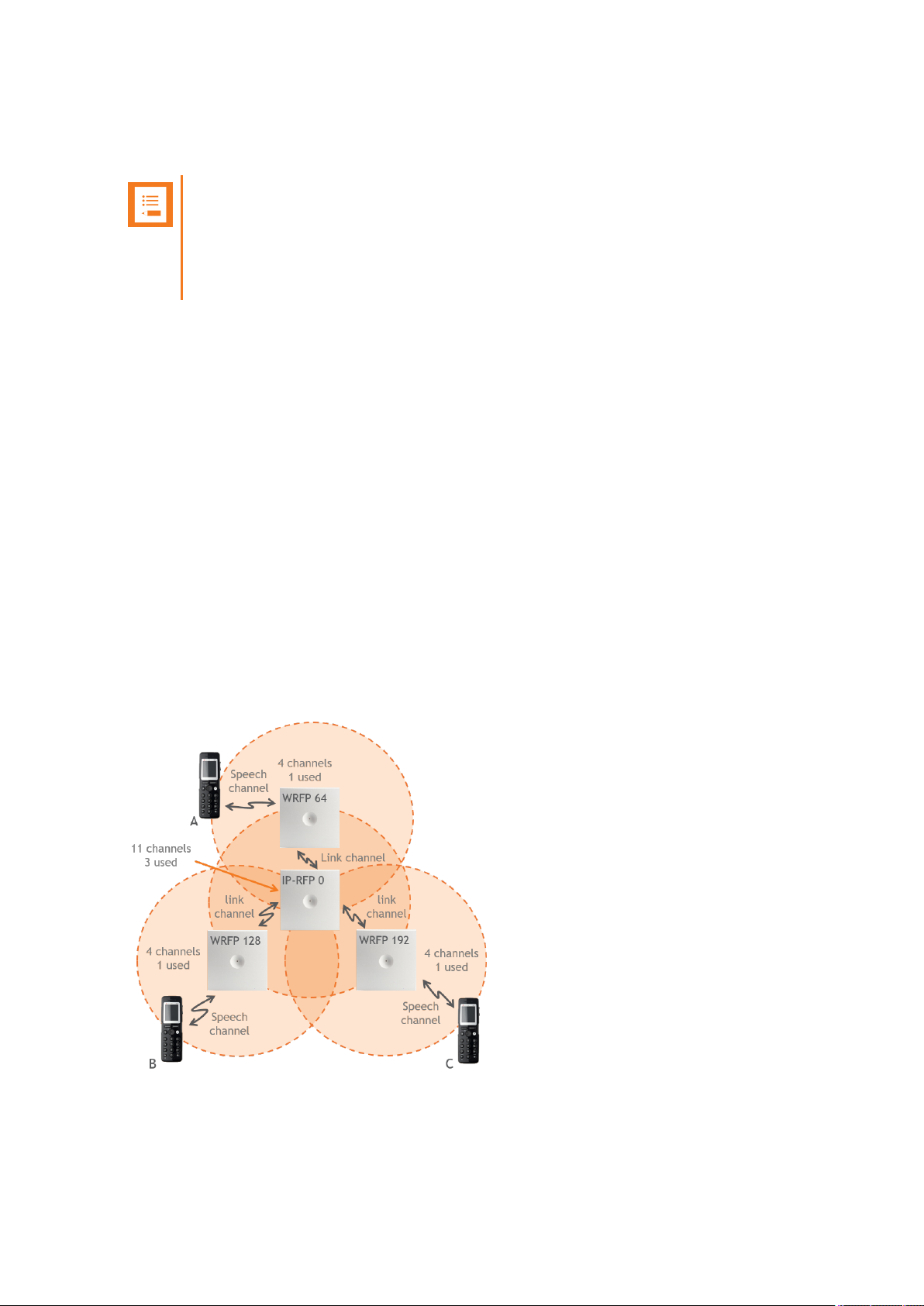
SpectralinkIP-DECT Server 200/400/6500 Installation and Configuration Guide
Numbering of Base Stations/Server 200/400 and Repeaters in a Normal Configuration
Note:
Repeater and base station/server RPNs must not be the same. Also, in a situation
where common overlap is present between the actual units, a repeater cannot have an
RPN that is similar to that of a base station/server or another repeater. If this occurs, handover between the different units is not possible.
First Repeater
l RPN of base station/server 200/400 + 64
l Base to synchronize on: RPN of base station/server
Second Repeater
l RPN of base station/server 200/400 + 128
l Base to synchronize on: RPN of base station/server
Third Repeater
l RPN of base station/server 200/400 + 192
l Base to synchronize on: RPN of base station/server
Below is an example of base station and repeater numbering in a normal configuration.
14215700-IG, Edition 8.0
April 2018, Originaldocument
74
Page 75

SpectralinkIP-DECT Server 200/400/6500 Installation and Configuration Guide
Numbering of Repeaters in a Repeater Daisy Chain Configuration
First Repeater in Chain
l RPN of base station/server 200/400 + 64
l Base to synchronize on: RPN of base station/server
Second Repeater in Chain
l RPN of base station/server 200/400 + 128
l Base to synchronize on: RPN of previous repeater
Third Repeater in Chain
l RPN base station/server 200/400 + 192
l Base to synchronize on: RPN of previous repeater
Below is an example of repeater numbering in a daisy chain configuration.
14215700-IG, Edition 8.0
April 2018, Originaldocument
75
Page 76

SpectralinkIP-DECT Server 200/400/6500 Installation and Configuration Guide
Using the Spectralink DECT Repeater With
ExternalAntenna
If coverage is needed in a remote area, synchronization can be established between the main system and a repeater by use of an external antenna. The external antenna establishes a radio link
between the main system and a Spectralink DECT Repeater.
Note:
Only the Spectralink external antenna (part no. 0231 9705 - including 1 m connection
cable) is approved along with the Spectralink DECT Repeater. The external antenna is
delivered with a 1 m connection cable. The connection cable is also available in 3 m (part
no. 1400 2704 and 7.5 m (part no. 1400 2706).
The Spectralink DECT Repeater is automatically configured to the external antenna
when connected.
Below is an example of using a Spectralink DECT Repeater with external antenna.
A repeater is placed at a remote location and a base station is placed at the main location. They are
too far away to allow the repeater to extend the coverage of the base station. Therefore, an external
antenna can be used to establish a connection between the two end points. As the external antenna
is a high gain directional antenna, it must point towards the base station you want to link with.
The radio link way must be stable and free of moving objects. The RSSI level of the main system at
the Spectralink DECT Repeater placed remotely must not be lower than 75.
Note:
Inside the area named "radio link" there is no radio coverage for handsets.
14215700-IG, Edition 8.0
April 2018, Originaldocument
76
Page 77

SpectralinkIP-DECT Server 200/400/6500 Installation and Configuration Guide
If a situation occurs where the primary synchronization for some reason breaks down, the Spectralink DECT Repeater will obtain synchronization on the alternative synchronization source.
Alternative Synchronization Ways
The Spectralink DECT Repeater with or without external antenna, 4 channels, can be programmed
to obtain synchronization on two radio units (base station, wireless server 200/400 or repeater).
Note:
The primary synchronization source has priority; the alternative synchronization source is
only in use as long as the primary synchronization source is down.
Technical Specifications - External Antenna
Electrical Properties
l Frequency range: 1880-1930 MHz
l Impedance: 50 Ω (DC-path to ground)
l Polarization: RHCP
l Gain: 7.5 - 8.0 dB
l 3 dB beamwidth horizontal: > 62°
l 3 dB beamwidth vertical: > 62°
l Front to back ratio: > 8 dB
l Return loss: < 15 dB
l Connector: SMB male
l One meter cable included
Environmental Conditions
l Operating temperature: -20º - 55º C (-4º - 131º F)
l Storage temperature: -40º - 85º C (-40º - 185º F)
Physical Characteristics
l Size: 100 x 100 x 42 mm (4 x 4 x 1.7 in.)
l Weight: 120 gr. (4.2 oz.)
l Only for indoor usage
14215700-IG, Edition 8.0
April 2018, Originaldocument
77
Page 78

SpectralinkIP-DECT Server 200/400/6500 Installation and Configuration Guide
Using the Spectralink IP-DECT Server
200/400 and Spectralink IP-DECT Base
Station With ExternalAntenna
Note:
Only the Spectralink external antenna (part no. 0231 9705) is approved along with the
Spectralink IP-DECT Server 200/400 and Spectralink IP-DECT Base Station . The
external antenna is delivered with a 1 m connection cable. The connection cable is also
available in 3 m (part no. 1400 2704 and 7.5 m (part no. 1400 2706).
The devices are automatically configured to the external antenna when connected.
First example (see illustration below) is an example of using a Spectralink IP-DECT Base Station
with external antenna.
The 2 base stations are too far apart to maintain full speech coverage between them. An external
antenna can be used on either side to create an overlap which allows for full speech coverage anywhere between the two base stations. Note that the range of RFP A is reduced when connected
with an external antenna. RFP A and the external antenna also operates on the same channel as
opposed to a repeater which always operates on a channel that is different from its host.
14215700-IG, Edition 8.0
April 2018, Originaldocument
78
Page 79

SpectralinkIP-DECT Server 200/400/6500 Installation and Configuration Guide
Second example (see illustration below) is an example of using Spectralink IP-DECT Base Stations,
both having external antennas. This scenario allows for coverage over very long distances.
Third example (see illustration below) is an example of using external antenna only on a Spectralink
IP-DECT Base Station or Spectralink IP-DECT Server 400 with built-in antenna turned off (requires
Multicell | IP-DECT Server 400 License on the Spectralink IP-DECT Server 400).
14215700-IG, Edition 8.0
April 2018, Originaldocument
79
Page 80

SpectralinkIP-DECT Server 200/400/6500 Installation and Configuration Guide
Fourth example (see illustration below) is an examle of using a Spectralink IP-DECT Server 400
(single cell solution) with external antenna.
Fifth example (see illustration below) is an example of using a Spectralink IP-DECT Server 200 with
external antenna.
14215700-IG, Edition 8.0
April 2018, Originaldocument
80
Page 81

SpectralinkIP-DECT Server 200/400/6500 Installation and Configuration Guide
How to Connect External Antenna to Device
Connect the external antenna cable to the antenna connector on the rear side of the Spectralink IPDECT Base Stations and Spectralink IP-DECT Server 200/400 and in the same way on the external
antenna.
Below is an illustration of the antenna connector. Use a screwdriver to remove the plastic carefully.
Below are illustrations of a Spectralink IP-DECT Server 200 and Spectralink IP-DECT Server 400
with external antenna.
14215700-IG, Edition 8.0
April 2018, Originaldocument
81
Page 82

SpectralinkIP-DECT Server 200/400/6500 Installation and Configuration Guide
Configuration Steps Overview
Below is an overview of the steps to follow in order to configure the Spectralink IP-DECT Server solution after having installed all system components and completed all pre-configuration tasks.
After following these steps, you will be able to make calls between handsets:
1. Power up the Spectralink IP-DECT Server and Spectralink DECTMedia Resource (if used).
For more information, see "Installing the Spectralink IP-DECT Server 200" on
page49,"Installing the Spectralink IP-DECT Server 400" on page54 and "Installing the Spectralink IP-DECT Server 6500 and Spectralink DECTMedia Resource" on page55 .
2. Change the IP address of the Spectralink IP-DECT Server.
For more information, see "To Configure a Static IP Address and Other Network Settings" on
page93.
3. Power up the Spectralink IP-DECT Base Station.
For more information, see "Installing the Spectralink IP-DECT Base Station" on page62.
Note:
Not relevant to the Spectralink IP-DECT Server 200.
4. Change the IP address of the Spectralink IP-DECT Base Station.
For more information, see "To Configure a Dynamic IP address" on page92.
Note:
Not relevant to the Spectralink IP-DECT Server 200.
5. Configure the Spectralink IP-DECT Base Station with the address of the Spectralink IPDECT Server.
For more information, see "Assigning Server Address to Spectralink IP-DECT Base Station
and Spectralink DECTMedia Resource" on page123.
Note:
Not relevant to the Spectralink IP-DECT Server 200.
6. SIP registration - configure the settings for the IP-PBX (Configuration > SIP). Remember to
reboot the server.
For more information, see "Configuring SIP and IP-PBX Settings" on page101.
7. Register/create users and enter values for user name, authentication user and authentication
password (depending on PBX type).
For more information, see "Handset Management" on page143.
8. Subscribe handset.
For more information, see "Registering Users and Subscribing Spectralink DECT Handsets"
on page139.
14215700-IG, Edition 8.0
April 2018, Originaldocument
82
Page 83

SpectralinkIP-DECT Server 200/400/6500 Installation and Configuration Guide
Note:
The above mentioned configuration steps are only the minimum steps for configuring a
system and being able to make calls between two handsets.
Depending on your solution, configuration of media resources, clusters, redundancy
server, handset sharing, phone book and MSF messaging can also be part of further configuration.
For more information, see:
l "Configuring Media Resource Settings" on page115
l "Configuring Clusters" on page118
l "Configuring Redundancy" on page177
l "Configuration of Handset Sharing" on page200
l "Configuring Corporate Phone Book/Directory " on page193
l "Messaging Over MSF" on page173
14215700-IG, Edition 8.0
April 2018, Originaldocument
83
Page 84

SpectralinkIP-DECT Server 200/400/6500 Installation and Configuration Guide
Configuring the Spectralink IP-DECT
Server/Spectralink DECTMedia Resource
Solution
This section provides you with information on basic network configuration of the Spectralink IPDECT Server 200/400/6500/Spectralink DECTMedia Resource solution and the web based Administration Page.
Note:
Configuration of Spectralink DECTMedia Resources and Clusters is not relevant to the
Spectralink IP-DECT Server 200/400.
Configuration of Spectralink IP-DECT Base Stations is not relevant to the Spectralink IPDECT Server 200.
The web based Administration Page is used to configure the different components of the Spectralink
IP-DECT Server solution.
Basic network settings can be obtained the following ways:
l From a DHCP server
Using DHCP the device requests and obtains an available IP address from a DHCP server.
The device also obtains other parameters such as the default gateway, subnet mask, DNS
server, Time server and other IP parameters from the DHCP server.
l Entered manually through web based Administration Page > Configuration > General >
General Configuration page.
Using manual network configuration, the IP-addresses and other networking parameters are
entered manually through the web based Administration Page.
14215700-IG, Edition 8.0
April 2018, Originaldocument
84
Page 85

SpectralinkIP-DECT Server 200/400/6500 Installation and Configuration Guide
Recommended Network Configuration
When configuring a Spectralink IP-DECT Server solution, Spectralink recommends doing it the following way:
l Spectralink IP-DECT Server 400/6500 using static IP address
This is to avoid sudden change of the IP address which would temporarily affect all base stations and thus the entire installation.
l Spectralink IP-DECT Server 200 using static IP address
l Spectralink DECTMedia Resources using static IP address
Like with the servers, this is to avoid sudden change of the IP address.
l Spectralink IP-DECT Base Stations using DHCP
This makes it easy to manage many base stations without having to keep track of many IP
addresses.
Note:
When the base stations are set up to DHCP, you need to use UPnP to discover the Wireless devices. In Windows Explorer the devices will appear under Network and Other
Devices as “<device name>-<Serial number> “ (e.g. Spectralink IP-DECT Server 65008442621 or MR6500-84532341).
Note:
Spectralink IP-DECT Base Stations and Spectralink DECTMedia Resources can be
managed from the web based Administration Page of the Spectralink IP-DECT Server.
If the Spectralink IP-DECT Server solution is configured as recommended above, it is possible to
assign options to the DHCP server making it extremely easy to configure all media resources and
base stations. If the Spectralink IP-DECT Server is configured using DHCP, it is necessary to
assign a reservation for the device on the DHCP server.
14215700-IG, Edition 8.0
April 2018, Originaldocument
85
Page 86

SpectralinkIP-DECT Server 200/400/6500 Installation and Configuration Guide
Assigning DHCP Server Options
Note:
Not relevant to the Spectralink IP-DECT Server 200.
This section provides you with information on basic network configuration of the Spectralink IPDECT Server 400/6500 solution and the web based Administration Page.
You can provide information about the static IP address of Spectralink IP-DECT Server 400/6500 in
the DHCP server through DHCP options. When defining the IP address of the Spectralink IP-DECT
Server 400/6500 in the DHCP server, all media resources and Spectralink IP-DECT Base Stations
are configured automatically.
The media resources and Spectralink IP-DECT Base Stations will include a Vendor Class Identifier
option (60) with the value KIRK.IP6000 and a request for the Vendor Specific Information option
(43) in the initial DHCP Discover request.
In the DHCP offer message, it will then expect the address of the Spectralink IP-DECT Server location in the Vendor Specific Information option (43), sub-option 43 encpapsulated as a string type
parameter.
On a Windows Server 2012 DHCP Management Cosole, the following steps will configure the correct DHCP option:
1. Right-click IPv4/IPv6, and click Define Vendor Classes....
2. Add a class new class:
l Display name: IP-DECT
l Description: Spectralink IP-DECT
l ASCII: KIRK.IP6000 (case sensitive)
3. Right-click IPv4/IPv6, and click Set Predefined Options....
4. Add a new option in the IP-DECT class:
l Name: IP-DECT Server
l Type: String
l Code: 43
l Description: IP address of the IP-DECT Server
5. Right-click Server Options, and click Configure Options.
6. Under Advanced, add option 43 in the Spectralink IP-DECT vendor class, and set the value
to the IP address of the Spectralink IP-DECT Server.
14215700-IG, Edition 8.0
April 2018, Originaldocument
86
Page 87

SpectralinkIP-DECT Server 200/400/6500 Installation and Configuration Guide
Using the Powershell, following commands will configure the correct DHCP options for a Spectralink
IP-DECT Server with the IP address 192.168.1.10:
netsh dhcp server add class IP-DECT "Spectralink IP-DECT"
netsh dchp server add optiondef 43 "IP-DECT Server" string 0 vendorr=IP- DECT comment="IP address of the IP-DECT Server"
netsh dhcp server set optionvalue 43 string vendor=IP-DECT
"192.168.1.10"
On a ISC DHCP server, the following configuration file fragment will be the correct DHCP options
for a Spectralink IP-DECT Server with the IP address 192.168.1.10:
option space ipdect code width 1 length width 1;
option ipdect.server code 43 = text;
option vendor-ipdect code 43 = encapsulate ipdect;
class "vendor-classes" {
match option vendor-class-identifier;
}
subclass "vendor-classes" "KIRK.IP6000" {
vendor-option-space ipdect;
option ipdect.server "192.168.1.10";
}
Discovering the Spectralink IP-DECT Components via UPnP
The Spectralink IP-DECT Server is setup with DHCP enabled by default. Therefore, you must use
UPnP to discover the Spectralink IP-DECT Server.
The Spectralink IP-DECT Server will appear under Network and Other Devices (using Windows
Explorer) as "KWS6500 -<Serial number> ", e.g. KWS6500-8442621
Below is an example of using UPnP to discover Spectralink IP-DECT Server 6500.
l Double-click the icon to access the web based Administration Page of the Spectralink IP-
DECT Server 6500.
14215700-IG, Edition 8.0
April 2018, Originaldocument
87
Page 88

SpectralinkIP-DECT Server 200/400/6500 Installation and Configuration Guide
Assigning DHCP Server Reservations
If the Spectralink IP-DECT Server/ Spectralink DECTMedia Resource is configured using DHCP, it
is necessary to assign a reservation for the device on the DHCP server. For more information about
this feature, contact your network administrator.
Accessing the Web Based Administration Page
The Spectralink IP-DECT Server, Spectralink DECTMedia Resources and Spectralink IP-DECT
Base Stations have their own web based Administration Page.
You can access the web based Administration Page through a standard web browser by entering
the IP address discovered by UPnP, along with the user name and password.
For more information, see "Discovering the Spectralink IP-DECT Components via UPnP" on the pre-
vious page.
Note:
If no IP address is received from the DHCP server, the server automatically falls back to
IP address 192.168.0.1
Password
The Spectralink IP-DECT Server, Spectralink DECTMedia Resources and Spectralink IP-DECT
Base Stations are delivered with a default user name and password.
l Default user name of the system is: admin
l Default password of the system is: admin
Note:
l After five successive failed login attempts, the web based Administration Page will
be locked for the next five minutes.
l After being idle for 20 minutes, the user is automatically logged out of the web
based Administration Page.
l Click Logout to logout manually from the web based Administration Page of the
Spectralink IP-DECT Server.
Note:
It is strongly recommended that you change the default password. You will be prompted
to change the password when logging on to the system the first time. For more information, see "Configuring Security Settings and Changing System Password" on page99.
14215700-IG, Edition 8.0
April 2018, Originaldocument
88
Page 89

SpectralinkIP-DECT Server 200/400/6500 Installation and Configuration Guide
About the Main Page of the Web Based Administration Page
The main page of the web based Administration Page for the Spectralink IP-DECT Server, Spectralink DECTMedia Resource and Spectralink IP-DECT Base Station consists of menus and submenus.
First you click a menu, and then you click one of the submenus to display the relevant page.
Spectralink IP-DECT Server
The web based Administration Page is used to configure the different solution components of the
Spectralink IP-DECT Server. For an overview and description of parameters on the different pages,
see "Parameter Overview" on page223.
14215700-IG, Edition 8.0
April 2018, Originaldocument
89
Page 90

SpectralinkIP-DECT Server 200/400/6500 Installation and Configuration Guide
Spectralink IP-DECT Base Station
The web based Administration Page of the Spectralink IP-DECT Base Station can be used in the following situations:
l Configuration - to specify to which Spectralink IP-DECT Server the Spectralink IP-DECT
Base Station should connect.
l Status Information
l Firmware update
Spectralink DECTMedia Resource
The web based Administration Page of the Spectralink DECTMedia Resource can be used in the following situations:
l Configuration - to specify to which Spectralink IP-DECT Server the Spectralink DECTMedia
Resource should connect.
l Status Information
l Firmware update
14215700-IG, Edition 8.0
April 2018, Originaldocument
90
Page 91

SpectralinkIP-DECT Server 200/400/6500 Installation and Configuration Guide
Configuring Network Settings
Through the web based Administration Page of the server, you can configure the network for the
Spectralink IP-DECT Server components using a static IP address or a dynamic IP address
(DHCP). For more information, see "Recommended Network Configuration" on page85.
Note:
As the Spectralink IP-DECT Server is a critical part of the SIP infrastructure, it is highly
recommended that you do not use DHCP.
Using a static IP address for the Spectralink IP-DECT Server is the preferred method. If
the device is configured using a static IP address, it is possible to assign options to the
DHCP server making it extremely easy to configure all base stations.
It is also possible to configure Simple Network Management Protocol (SNMP).
14215700-IG, Edition 8.0
April 2018, Originaldocument
91
Page 92

Field Setting
General Configuration - Pv4
Method Select DHCP assigned.
Note: Selecting DHCP, all other network settings are provided auto-
matically.
SpectralinkIP-DECT Server 200/400/6500 Installation and Configuration Guide
To Configure a Dynamic IP address
It is recommended to use a dynamic IP address (DHCP) for base stations.
To configure network settings (dynamic IP address) for the base stations from the web based Administration Page:
1. Click Configuration, and then click General.
2. On the General Configuration page, enter the following data:
3. Click Save.
14215700-IG, Edition 8.0
April 2018, Originaldocument
92
Page 93

Field Setting
General Configuration - IPv4
Method Default value: DHCP assigned (dynamic IP address)
Select Use Static IP Address to configure a static IP
address.
Note: When using a static IP address, it is also necessary to configure other network settings below such as
DNS and NTP settings.
For more information, see also "Recommended Network
Configuration" on page85.
IP addr Enter the IP address of the Spectralink IP-DECT Server.
Netmask Enter a new network mask. Contact your system admin-
istrator for more information.
Gateway Enter the IP address of the default gateway.
The default gateway serves as an access point to
another network.
Contact your system administrator for more information.
MTU (Maximum Translation
Unit) (Optional)
Enter the size of the largest packet, that your network protocol can transmit.
SpectralinkIP-DECT Server 200/400/6500 Installation and Configuration Guide
To Configure a Static IP Address and Other Network Settings
It is highly recommended to use a static IP address for the Spectralink IP-DECT Server and Spectralink DECTMedia Resource.
To configure IP address, DNS and NTP settings for the Spectralink IP-DECT Server and Spectralink DECTMedia Resource from the web based Administration Page:
1. Click Configuration, and then click General.
2. On the General Configuration page, enter the following data:
14215700-IG, Edition 8.0
April 2018, Originaldocument
93
Page 94

Field Setting
General Configuration - IPv6
Method (Optional) Default value:Disabled
If not using IPv4, select Static to set the following settings manually: IPv6 address, Subnet Prefix Length,
Default Gateway, Primary DNS Server, and Secondary
DNS Server.
Other possible settings are:
l Stateless Address Autoconfiguration (SLAAC):
An IPv6 address is automatically generated based on
the prefix being advertised on the connected network.
l Statefull (DHCPv6): IPv6 address, DNS servers and
DNS search list will be obtained from router.
Address/prefix (Optional) It is possible to enter a prefix (Static IPv6 address with an
optional prefix length).
Address and prefix length must be separated by: /
Default gateway (Optional) Enter IP address of the default gateway. The default gate
way serves as an access point to another network.
General Configuration - Ethernet
VLAN (Optional) It is possible to enter the VLAN Identifier (VID) according
to IEEE 802.1Q specifying the VLAN to which the device
belongs.
Note: If this setting is used, network access from outside
the VLAN is no longer possible.
The Spectralink IP-DECT Server supports 4094 different
VLANs.
Possible values: 1-4094
General Configuration - DNS (Domain Name System)
Hostname (FQDN)(Optional) The hostname (Fully Qualified Domain Name) will be
inserted into the SIP Contact and via headers. The hostname will also be published via DHCP, and if the network
infrastructure supports it, the device will be reachable via
this hostname.
E.g. Example.spectralink.com
Search Domain (Optional) Domain name used for resolving host names without a
domain.
SpectralinkIP-DECT Server 200/400/6500 Installation and Configuration Guide
14215700-IG, Edition 8.0
April 2018, Originaldocument
94
Page 95

Field Setting
Primary Server (Optional) Enter the IP address of the Primary DNS server.
Secondary Server (Optional) Enter the IP address of the Secondary DNS server.
General Configuration - NTP (Network Time Protocol)
Server (Optional) Enter the IP address of the NTP server from which the
system will obtain the current time.
Timezone (Optional) Select the wanted time zone. The time zones include day-
light saving times.
Posix timezone string (Optional) Customized time zone setting. The string must be in
POSIX time zone format.
General Configuration - UPnP
Enabled (Optional) Enabled by default. If enabled, the device is UPnP dis-
coverable.
UPnP is an acronym for Universal Plug and Play. If the
IP address of the device is unknown (e.g. forgotten or
DHCP-assigned), UPnP can be used to easily identify
the IP address of the device.
Note: If My Network Places in Windows is setup to
show icons for networked UPnP devices, every Spectralink IP-DECT Server, Media resource and Base station will be present in My Network Places.
Broadcast announcements
(Optional)
Specifies if UPnP announcements are broadcasted.
If enabled, the device broadcasts announcements automatically.
General Configuration - Remote syslog
Host (Optional) Enter the host or IP address of the remote syslog server.
If specified, messages will be sent to the server.
Port Server port used for remote syslog.
Default value: 514
Facility Remote syslog facilities used for log messages.
Default value: Local 0
Refer to RFC5424.
SpectralinkIP-DECT Server 200/400/6500 Installation and Configuration Guide
14215700-IG, Edition 8.0
April 2018, Originaldocument
95
Page 96

Field Setting
Level Log level to send via syslog.
Possible values: emergency. critical, error, warning,
notice, info or debug.
Default value:Info
Scope (Optional) Scope of syslog settings.
If set to all, the settings will override any local settings on
e.g. connected base stations.
If set to server only, these settings will only apply to the
server.
If set to server and mr, these settings will only apply to
the server and media resource.
Default value: all
General Configuration - SNMP
Enabled (Optional) If enabled, access to the SNMP is allowed, and the
server will respond to SNMP requests.
Community (Optional) SNMP Community name (public). The server will
respond to requests from a manager in this community.
Trap host (Optional) Address of SNMP trap host to which SNMP traps are
sent.
Trap community (Optional) SNMP trap Community name used for sending traps.
System location (Optional) Information about the physical location of this host.
E.g. telephone closet, 3rd floor
System contact (Optional) The textual identification of the contact person for this
host, together with information about how to contact
them.
SpectralinkIP-DECT Server 200/400/6500 Installation and Configuration Guide
3. Click Save.
14215700-IG, Edition 8.0
April 2018, Originaldocument
96
Page 97

SpectralinkIP-DECT Server 200/400/6500 Installation and Configuration Guide
Simple Network Management Protocol (SNMP)
The Spectralink IP-DECT product portfolio support the Simple Network Management Protocol
(SNMP) version 2c for monitoring system health and performance.
A number of general MIBs are supported by Spectralink IP-DECT Servers, Spectralink
DECTMedia Resources and Spectralink IP-DECT Base Stations. These provide general information e.g. uptime, number of received/transmitted udp datagrams etc.
The following MIBs are implemented on the DECT devices:
l IF
l IP
l IP-FORWARD
l TCP
l EtherLike
l SNMPv2
l IPV6
l UDP
In addition to the general information mentioned above, specific Spectralink DECT information is
available on the Spectralink IP-DECT Server only. This information is defined in a SPECTRALINKIPDECT MIB, which includes the following groups of information:
l dectGeneralInfoGroup
Objects which provide general information about the IP-DECT server.
l dectGeneralStatisticsGroup
Objects which provide general statistics about the IP-DECT server.
l dectUserInfoGroup
Objects which provide information about users on the IP-DECT server.
l dectRfpInfoGroup
Objects which provide information about base stations (RFP) configured on the IP-DECT
server.
l dectMediaResourceInfoGroup
Objects which provide information about media resources configured on the IP-DECT server.
l dectNotificationsGroup
Notifications that are generated by the IP-DECT server.
SNMP along with the associated Management Information Base (MIB), encourage trap-directed
notification. The SPECTRALINK-IPDECT MIB includes a number of traps, also called notifications.
One example of a notification is "Connection to a base station is lost", another example is "Base station lost DECT synchronization". Please refer to the SPECTRALINK-IPDECT MIB document (available at http://support.spectralink.com/products) for more details on the information available via
SNMP.
14215700-IG, Edition 8.0
April 2018, Originaldocument
97
Page 98

Field Setting
General Configuration - SNMP
Enabled
(Optional)
If enabled, access to the SNMP is allowed, and the server will respond to
SNMP requests.
Community
(Optional)
SNMP Community name (public). The server will respond to requests
from a manager in this community.
Trap host
(Optional)
Address of SNMP trap host to which SNMP traps are sent.
Trap community
(Optional)
SNMP trap Community name used for sending traps.
System location
(Optional)
Information about the physical location of this host.
E.g. telephone closet, 3rd floor
System contact
(Optional)
The textual identification of the contact person for this host, together with
information about how to contact them.
SpectralinkIP-DECT Server 200/400/6500 Installation and Configuration Guide
To Configure SNMP Settings
1. Click Configuration, and then click General.
2. On the General Configuration page, enter the following data:
3. Click Save.
14215700-IG, Edition 8.0
April 2018, Originaldocument
98
Page 99

Field Setting
Security Configuration - Administrator Authentication
Current password Enter the current password.
New username Enter a new username.
New password (Optional) Enter a new password.
New password again
(Optional)
Enter the new password again to confirm.
Strict password requirements
(Optional)
If enabling strict password requirements, the device can
be configured to enforce certain security rules and naming
conventions. For more information, see "Strict Password
Requirements" on the next page.
Note: Once enabled, this setting can only be disabled by a
factory reset (Configuration > Factory Reset) that will
remove all configuration and user data.
Password expiration (Optional) Select when you want the password to expire.
Possible values: Never, 30 days or 90 days.
Default value: Never
Note: Once enabled, this setting can only be disabled by a
factory reset (Configuration > Factory Reset) that will
remove all configuration and user data.
Security Configuration - Data protection
Allow unencrypted HTTP
(Optional)
HTTPS is forced by default.
If enabled, HTTP support is supported instead of HTTPS.
Note: Enabling unencrypted HTTP can cause passwords
and other sensitive data to be transmitted in clear text on
the network.
SpectralinkIP-DECT Server 200/400/6500 Installation and Configuration Guide
Configuring Security Settings and Changing System Password
It is recommended to change the password for the devices. To change the password and other
security settings from the web based Administration Page of the different devices (server, base stations and media resources):
1. Click Configuration, and then click Security.
2. On the Security Configurationpage, enter the following data:
14215700-IG, Edition 8.0
April 2018, Originaldocument
99
Page 100

Field Setting
Allow remote logging
(Optional)
If enabled, remote logging is allowed.
Remote logging allows for Spectralink debug tools to
extract debug information from the unit.
Remove user passwords from
exported data (Optional)
If enabled, users passwords are prevented from being
included when data are exported from the Spectralink IPDECT Server,e.g. when exporting the user list to XML
files or CSV files.
Note: Enabling this will exclude the user database from
full system backups.
Note: Once enabled, this setting can only be disabled by a
factory reset (Configuration > Factory Reset) that will
remove all configuration and user data.
SpectralinkIP-DECT Server 200/400/6500 Installation and Configuration Guide
3. Click Save.
Strict Password Requirements
When using strict password requirements, the password of the web based Administration Page
must meet the following requirements:
l Minimum length of 8 characters
l Must contain characters from at least two of the following classes: upper case letters, lower
case letters, numbers and special characters
l Must not be simple or dictionary based words
l Must be different from the last three passwords
l Must not contain more than two successive identical characters
14215700-IG, Edition 8.0
April 2018, Originaldocument
100
 Loading...