

Page 1

14212650-IG, Edition 1.0
April 2018, Originaldocument
Spectralink IP-DECTServer 200
Deployment and Installation
Guide
Page 2

Copyright Notice
© 2018 Spectralink Corporation All rights reserved. SpectralinkTM, the Spectralink logo and the
names and marks associated with Spectralink’s products are trademarks and/or service marks of
Spectralink Corporation and are common law marks in the United States and various other countries. All other trademarks are property of their respective owners. No portion hereof may be reproduced or transmitted in any form or by any means, for any purpose other than the recipient’s
personal use, without the express written permission of Spectralink.
All rights reserved under the International and pan-American Copyright Conventions. No part of this
manual, or the software described herein, may be reproduced or transmitted in any form or by any
means, or translated into another language or format, in whole or in part, without the express written
permission of Spectralink Corporation.
Do not remove (or allow any third party to remove) any product identification, copyright or other
notices.
Notice
Spectralink Corporation has prepared this document for use by Spectralink personnel and customers. The drawings and specifications contained herein are the property of Spectralink and shall
be neither reproduced in whole or in part without the prior written approval of Spectralink, nor be
implied to grant any license to make, use, or sell equipment manufactured in accordance herewith.
Spectralink reserves the right to make changes in specifications and other information contained in
this document without prior notice, and the reader should in all cases consult Spectralink to determine whether any such changes have been made.
NO REPRESENTATION OR OTHER AFFIRMATION OF FACT CONTAINED IN THIS
DOCUMENT INCLUDING BUT NOT LIMITED TO STATEMENTS REGARDING CAPACITY,
RESPONSE-TIME PERFORMANCE, SUITABILITY FOR USE, OR PERFORMANCE OF
PRODUCTS DESCRIBED HEREIN SHALL BE DEEMED TO BE A WARRANTY BY
SPECTRALINK FOR ANY PURPOSE, OR GIVE RISE TO ANY LIABILITY OF SPECTRALINK
WHATSOEVER.
Warranty
The Product Warranty and Software License and Warranty and other support documents are available at http://support.spectralink.com/.
Contact Information
US Location
+ 1 800-775-5330
Spectralink Corporation
2560 55th Street
Boulder, CO 80301
USA
info@spectralink.com
UK Location
+44 (0) 20 3769 9800
Spectralink Europe UK
329 Bracknell, Doncastle Road
Bracknell, Berkshire, RG12 8PE
United Kingdom
infoemea@spectralink.com
Denmark Location
+45 75602850
Spectralink Europe ApS
Bygholm Søpark 21 E Stuen
8700 Horsens
Denmark
infoemea@spectralink.com
Page 3

Contents
About This Guide 4
Related Documentation 5
Description - Spectralink IP-DECT Server 200 6
Power Requirements for the Spectralink IP-DECT Server 200 6
Spectralink IP-DECT Server 200 Appearance and Components 7
Spectralink IP-DECT Server 200 Reset Button 8
Spectralink IP-DECT Server 200 LED Indicators 9
When Ordering Handsets and Spectralink IP-DECT Server
200 10
Special Transmission Limitations and Requirements 10
Prepare your Handsets and Spectralink IP-DECT Server 200
for Installation 11
Find the Best Installation Locations 12
Wall-Mount and Power on the Spectralink IP-DECT Server
200 13
Different Installation Use Cases 15
Installing a Single Spectralink IP-DECT Server 200 in a Small Area 15
Installing Multiple Spectralink IP-DECT Server 200 in a Small Area 16
Installing Single Spectralink IP-DECT Server 200s in Large Areas 17
Installing Multiple Spectralink IP-DECT Server 200s in Large Areas (1) 18
Installing Multiple Spectralink IP-DECT Server 200s in Large Areas (2) 19
Product Compatibility 20
14212650-IG, Edition 1.0
April 2018, Originaldocument
Page 4

About This Guide
This guide describes how to deploy and install a Spectralink IP-DECT Server 200. It does not
describe the configuration of the Spectralink IP-DECT Server 200.
Configuration of the Spectralink IP-DECT Server can be done using the following 3 methods:
l DHCP Option pointing to enterprise own Provisioning Server
l Manual configuration
l Configuration done by service provider (when deployed with UCaaS platforms).
It is assumed, that your handsets have been registered to the system, so that you can subscribe
each handset using an activation code - if needed.
14212650-IG, Edition 1.0
April 2018, Originaldocument
Page 5
Related Documentation
All Spectralink documents are available at http://support.spectralink.com/.
Safety and Handling information is available online at http://support.spectralink.com/products.
Regulatory information is available online at http://support.spectralink.com/products.
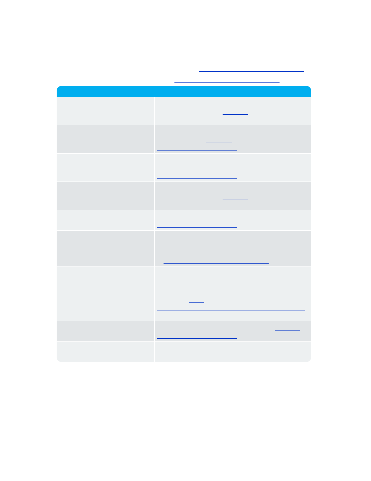
Subject Documentation
Spectralink DECT Handset For more information about the handset, refer to the user
guide available online at http://sup-
port.spectralink.com/products.
Spectralink IP-DECT/DECT
Server
For more information about the server, refer to the guide
available online at http://sup-
port.spectralink.com/products.
Spectralink DECT Repeater For more information about the repeater, refer to the
guide available online at http://sup-
port.spectralink.com/products.
Provisioning For more information about provisioning, refer to the
guide available online at http://sup-
port.spectralink.com/products.
Spectralink Technical Bulletins Available online at http://sup-
port.spectralink.com/products.
Release Notes Document that describes software changes, bug fixes,
outstanding issues, and hardware compatibility considerations for new software releases. Available online
at http://support.spectralink.com/products.
Spectralink DECT Training material
In order to gain access to the Spectralink training material, you must attend training and become Spectralink Certified Specialist.
Please visit http://-
partneraccess.spectralink.com/training/classroom-training for more information and registration.
Regulatory information Regulatory information is available online at http://sup-
port.spectralink.com/products.
Safety and Handling Information Safety and Handling information is available online at
http://support.spectralink.com/products.
14212650-IG, Edition 1.0
April 2018, Originaldocument
Page 6

Description - Spectralink IP-DECT
Server 200
The Spectralink IP-DECT Server 200 is a single cell system (one built-in base station in the
server) supporting SIP lines only.
The Spectralink IP-DECT Server 200 is designed with connector for External Antenna.
Up to 3 additional Spectralink DECT Repeaters can be added to the Spectralink IP-DECT
Server 200.
The Spectralink IP-DECT Server 200 supports up to 12 registered handsets and 6 simultaneous calls.
The DECT radius of coverage is up to 600 meters/2000 feet with a handset in free sight.
Power Requirements for the Spectralink IP-DECT
Server 200
l Power over Ethernet (PoE 802.3af).
l Maximum power supply consumption is 3.0W (IEEE 802.3af class 1 device).
Use a standard PoE adapter or a PoE-enabled port on an ethernet switch adhering to PoE
802.3af when connecting the Spectralink IP-DECT Server 200 to a PoE power source.
Use an 8V-DC power supply when using a port without PoE.
14212650-IG, Edition 1.0
April 2018, Originaldocument
Page 7
14212650-IG, Edition 1.0
April 2018, Originaldocument
7
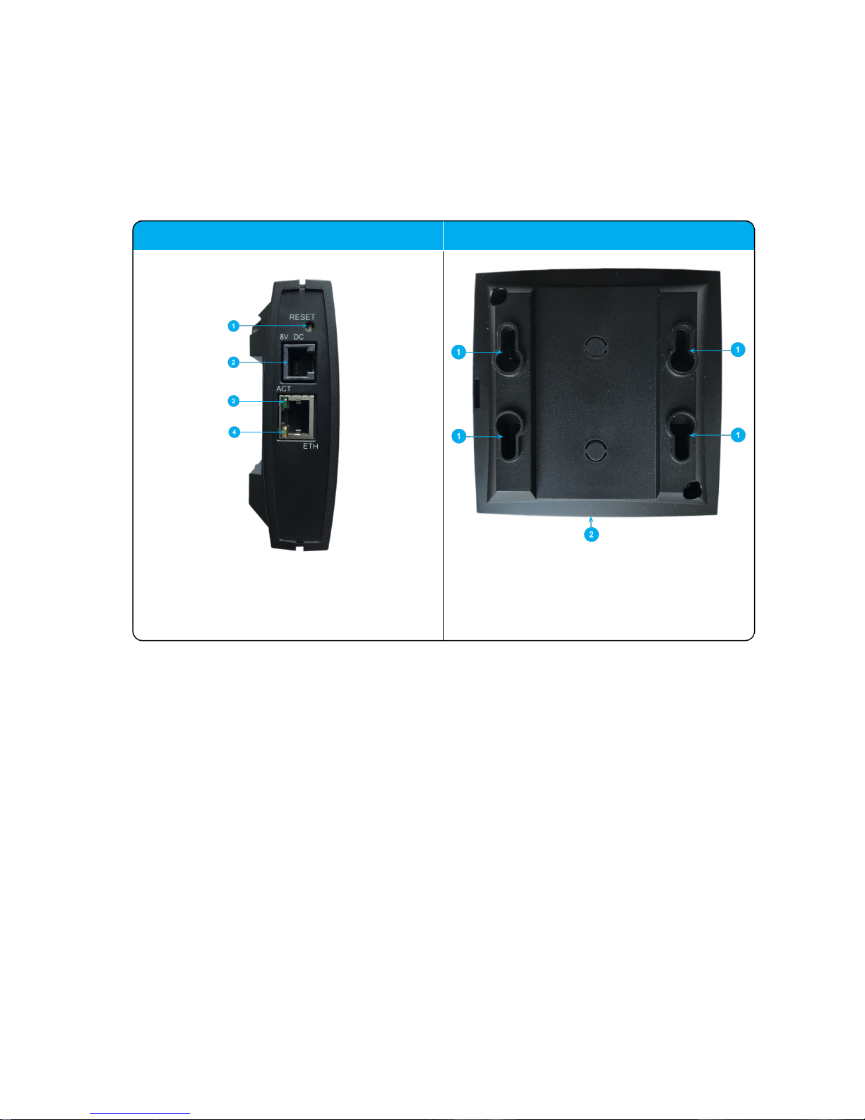
Spectralink IP-DECT Server 200 Appearance and Components
Below you will find a description of the Spectralink IP-DECT Server 200 appearance and components:
Spectralink IP-DECT Server 200 - bottom Spectralink IP-DECT Server 200 - rear
1. Resetbutton
2. DC
3. LINK/ActivityIndicator
4. ETH port (power supply by PoE)
1. Holesfor wall mounted screws
2. Connection to LAN
SpectralinkIP-DECTServer 200 Deployment and Installation Guide
Page 8

14212650-IG, Edition 1.0
April 2018, Originaldocument
8
Spectralink IP-DECT Server 200 - front
1. LED
Spectralink IP-DECT Server 200 Reset Button
You can restart or reset the Spectralink IP-DECT Server 200 by pressing the Reset button on the
bottom of face plate of the server.
The following table contains a description of the different actions that take place when pressing the
Reset button.
Press button Action
Short press (2 to 5 sec.) System restarts when button is released.
Long press (5 to 9 sec.) until front LED
flashes red, then release button
Resets the system to factory default settings (original IP
settings - DHCP) and restarts the system. Firmware version is not affected.
SpectralinkIP-DECTServer 200 Deployment and Installation Guide
Page 9

14212650-IG, Edition 1.0
April 2018, Originaldocument
9
Spectralink IP-DECT Server 200 LED Indicators
Below you will find information about LED indicators on the server.
Front Cover
The server front cover has one indicator describing the server faults and failures. The indicator is off
when the server is not powered. The LED flashes when the server initializes. The indicator is on
when the server is operating.
LED Indicator Meaning
Steady green OK and idle.
Slow green flashing OK and active voice call.
Fast green flashing Busy (all channelsare in use).
Steady red Reset/shutdown in progress.
Steady red for 5 seconds followed by
fast red flashing
Reset to factory settings.
Red flashing Error or rebooting
LAN Port on Face Plate
LED Indicator Meaning
LINK Indicator - yellow Link layer software has established connection.
LINK Indicator - green flashing Activity
SpectralinkIP-DECTServer 200 Deployment and Installation Guide
Page 10

14212650-IG, Edition 1.0
April 2018, Originaldocument
10
When Ordering Handsets and Spectralink
IP-DECT Server 200
Note:
It is recommended to plan your installation before ordering the Spectralink DECT Handsets and Spectralink IP-DECT Server 200.
1. Allocate up to 4 - 6 handsets per Spectralink IP-DECT Server 200.
Note:
The unit provides a coverage radius of approximately 75 meter/245 feet and supports 6 simultaneous calls.
l If you want to use phone calls with all handsets all the time, allocate up to 6 handsets per
Spectralink IP-DECT Server 200.
l If you want to allow more users to use the system, you can allocate up to 12 handsets per
Spectralink IP-DECT Server 200 (up to any 6 handsets can be used at the same time).
2. Determine which handsets will be associated with each new (or existing) Spectralink IPDECT Server 200 on your virtual PBX. This will ensure you receive correct activation codes
that link your handset accounts with your Spectralink IP-DECT Server 200s when you order.
3. Within the same 30 meters/100-feet radius you can install up to 5 Spectralink IP-DECT Server
200s.
Example: 5 Spectralink IP-DECT Server 200s in the same 30 meters/100-feet radius support
up to 20 simultaneous calls, and up to 30 handsets in normal use.
Special Transmission Limitations and Requirements
l In multiple floor installations, transmission range across floors will likely be less than 75
meters/245-feet.
l Transmission range across heavy walls will likely be less than 75 meters/245-feet.
l Spectralink IP-DECT Server 200s are normally installed at or near the center of a 75
meters/245-feet radius cell.
At the Spectralink IP-DECT Server 200 installation point, either Ethernet with PoE or Ethernet without PoE plus a nearby AC outlet and a PoE AC adaptor / PoE injector are required.
SpectralinkIP-DECTServer 200 Deployment and Installation Guide
Page 11

14212650-IG, Edition 1.0
April 2018, Originaldocument
11
Prepare your Handsets and Spectralink
IP-DECT Server 200 for Installation
Before permanently installing Spectralink IP-DECT Server 200s, complete the following steps:
1. Charge the battery in the handsets so the handsets can be subscribed and tested.
For more information, see Handset User Guides.
2. Turn on the Spectralink IP-DECT Server 200(s) and verify the power LED is light is on.
For more information, see "Power Requirements for the Spectralink IP-DECT Server 200" on
page6 and "Spectralink IP-DECT Server 200 LED Indicators" on page9.
3. Subscribe the new handsets to the server(s). Also, if needed, ensure that you have the activation codes for the handsets ready.
For more information about subscribing the handset and creating Login, see Handset User
Guides.
4. Before physically installing the Spectralink IP-DECT Server 200 onto walls:
l Place the Spectralink IP-DECT Server 200s close to their planned locations.
l Establish test calls between handsets in the areas where they will be used.
l Verify range and sound quality.
l Change the location of the Spectralink IP-DECT Server 200 if necessary to ensure optimal
call coverage and voice quality.
SpectralinkIP-DECTServer 200 Deployment and Installation Guide
Page 12

14212650-IG, Edition 1.0
April 2018, Originaldocument
12
Find the Best Installation Locations
1. Avoid areas with large metal surfaces and heavy machinery that may interfere with base unit
signals.
l Keep Spectralink IP-DECT Server 200s at least 1,2 meters/4 feet away from steel con-
structions.
l Do not place Spectralink IP-DECT Server 200s directly on metallic surfaces.
l Do not hide Spectralink IP-DECT Server 200s behind furniture or other physical objects.
l Do not paint Spectralink IP-DECT Server 200s. Paint contains metallic/carbon particles
that can affect transmission.
2. Locate ethernet access and either PoE or AC power outlets required to support the Spectralink IP-DECT Server 200s.
Note:
Order Spectralink IP-DECT Server 200 with AC Adaptor bundle if you do not have
PoE, or simply add a standard PoE switch or standard PoE injector to power the
server. Depending on the type of product bundle ordered - the AC power supply
for the IP-DECT Server 200 may be included.
3. Verify with the end users where coverage is needed so the Spectralink IP-DECT Server 200
can be placed near center of the 75 meters/245-feet radius where users are normally situated.
Tip:
Also identify areas where coverage is not required to simplify the installation.
4. SpectralinkIP-DECT Server 200s should preferably be placed between 2.4 - 3.6 meters/8 12 feet high on a wall (and no higher than 6 meters/20 feet). If placed lower, a passersbymay
interfere with the signal. The connectors can be pointed either up or down.
5. Do NOT install units upside down or on the ceiling. Doing so decreases coverage by 40 - 50%.
6. Ensure there is no heavy use of DECT headsets or residential DECT phone systems with individual transmitters in the same area you are installing your additional DECT devices. This can
cause interference and could affect performance of the Spectralink IP-DECT Server 200s.
SpectralinkIP-DECTServer 200 Deployment and Installation Guide
Page 13

14212650-IG, Edition 1.0
April 2018, Originaldocument
13
Wall-Mount and Power on the Spectralink
IP-DECT Server 200
For best RF coverage, the Spectralink IP-DECT Server 200 must be mounted vertically on walls.
1. Mount the Spectralink IP-DECT Server 200 on the wall using the anchors and screws accompanying the product.
Note:
When you place the Spectralink IP-DECT Server 200 on the screws, ensure that
the screws do not touch the printed circuit board.
1. Holesfor wall mounted screws
2. RJ45 port
2. Connect the RJ45 plug to the ethernet connector at the bottom of the Spectralink IP-DECT
Server 200.
SpectralinkIP-DECTServer 200 Deployment and Installation Guide
Page 14

14212650-IG, Edition 1.0
April 2018, Originaldocument
14
3. After installing the Spectralink IP-DECT Server 200 you need to power it up.
SpectralinkIP-DECTServer 200 Deployment and Installation Guide
Page 15

14212650-IG, Edition 1.0
April 2018, Originaldocument
15
Different Installation Use Cases
Installing a Single Spectralink IP-DECT Server 200 in a
Small Area
Small area is defined as: a radius of less than 30 meters/100 feet.
1. Follow the previous instructions and select the optimal location for the Spectralink IP-DECT
Server 200 within a 30 meter/100-feet radius cell that contains the users and the areas where
they are situated.
2. If the coverage area has multiple floors or goes across heavy walls, the Spectralink IP-DECT
Server 200’s range may be limited to ~15 meter/~50 feet or less for the floor above or across
the heavy walls.
Test the Spectralink IP-DECT Server 200s’ range and call quality before permanently
installing them.
SpectralinkIP-DECTServer 200 Deployment and Installation Guide
Page 16

14212650-IG, Edition 1.0
April 2018, Originaldocument
16
Installing Multiple Spectralink IP-DECT Server 200 in a
Small Area
Small area is defined as: a radius of less than 30 meters/100 feet.
The image below shows a single-cell configuration supporting up to 5 Spectralink IP-DECT Server
200s within a 30 meters/100-feet radius. Users can talk within their own 30 meters/100-feet cell.
1. Follow the previous instructions and select the optimal locations for up to 5 Spectralink IPDECT Server 200s serving up to 30 handset users and the areas where they are situated.
Ideally, mount the individual Spectralink IP-DECT Server 200s about 0,6 meters/2 feet apart
from each other, but place all near the center of the cell as in the diagram above.
2. In coverage areas with multiple floors or heavy walls, the Spectralink IP-DECT Server 200s’
range may be limited to ~15 meters/~50 feet or less for the floors above or across the heavy
walls.
Test the Spectralink IP-DECT Server 200s’ range and call quality before permanently
installing them.
l The same limit of up to 5 Spectralink IP-DECT Server 200s per 30 meters/100-feet radius
cell applies across floors and heavy walls.
l You will achieve the best results by mounting all the Spectralink IP-DECT Server 200s
either high on the wall near where most users reside most of the time, or on the side of any
heavy wall where most users reside most of the time.
SpectralinkIP-DECTServer 200 Deployment and Installation Guide
Page 17

14212650-IG, Edition 1.0
April 2018, Originaldocument
17
Installing Single Spectralink IP-DECT Server 200s in
Large Areas
Large areas defined as: each area with a radius larger than 30 meters/100 feet; 30 meters/100-feet
cells do not overlap.
The image below shows 2 independent cells over 30 meters/100 feet apart with 1 Spectralink IPDECT Server 200 in each.
The image below shows 2 independent cells over 30 meters/100 feet apart with 1 Spectralink IPDECT Server 200 in each.
1. Follow the previous instructions and select the optimal location for each Spectralink IP-DECT
Server 200 within its own 30 meters/100-feet radius cell.
2. The cells in this configuration do not overlap, which means each Spectralink IP-DECT Server
200 can be installed and will operate independently.
SpectralinkIP-DECTServer 200 Deployment and Installation Guide
Page 18

14212650-IG, Edition 1.0
April 2018, Originaldocument
18
Installing Multiple Spectralink IP-DECT Server 200s in
Large Areas (1)
Large areas defined as: each area with a radius larger than 30 meters/100 feet; 30 meters/100-feet
cells do not overlap.
The image below shows 2 independent cells over 30 meters/100 feet. apart with 1 Spectralink IPDECT Server 200 in each.
1. Follow the previous instructions for installing multiple Spectralink IP-DECT Server 200s and
select the optimal locations for up to 5 Spectralink IP-DECT Server 200s.
2. If each cell has a ~30 meters/~100 feet radius that does not overlap with adjacent cells, then
each Spectralink IP-DECT Server 200 can be installed and will operate independently.
3. If the 30 meters/100 feet radius cells overlap, then the maximum number of Spectralink IPDECT Server 200s installed in the area that overlaps must be 5 or fewer to avoid interference.
See "Installing Multiple Spectralink IP-DECT Server 200s in Large Areas (2)" on the next
page.
SpectralinkIP-DECTServer 200 Deployment and Installation Guide
Page 19

14212650-IG, Edition 1.0
April 2018, Originaldocument
19
Installing Multiple Spectralink IP-DECT Server 200s in
Large Areas (2)
Large areas defined as: radius larger than 30 meters/100 feet; 30 meters/100-feet cells overlap.
The image below shows overlapping cells supporting up to 5 base units (total).
Users can talk within their own 30 meters/100-feet radius cells. Users from both cells can talk in the
common (overlapping) area. Cells on adjacent floors can also overlap.
1. Follow the previous instructions for installing multiple base units and select the optimal locations for up to 5 base units.
2. Where the 30 meters/100 feet radius cells overlap, then the maximum number of base units
installed in the area that overlaps must be 5 or fewer to avoid any interference. This includes
where adjacent floors may overlap.
SpectralinkIP-DECTServer 200 Deployment and Installation Guide
Page 20

14212650-IG, Edition 1.0
April 2018, Originaldocument
20
Product Compatibility
If you have any questions about product compatibility, contact your system administrator.
You can use the Spectralink IP-DECT Server 200 with other Spectralink products as identified by
the type approval model ID and/or part number located on the label of the product.
Spectralink Server
Spectralink IP-DECT Server 200 K005 (7234 5600/723 45601)
Power Supply, 8.0V DC 8464 2600
External Antenna (with 1 m connection cable) 0231 9705
Connection cable for External Antenna, 3 m 1400 2704
Connection cable for External Antenna, 7.5 m 1400 2706
Spectralink DECT Repeater
Spectralink DECT Repeater 1G8, 2 channels, with
connector for external antenna
K018B (0244 0000)
Spectralink DECT Repeater 1G9, 2 channels, with
connector for external antenna
K018B (0244 1000)
Spectralink DECT Repeater 1G8, 2 channels,
without connector for external antenna
K018 (0244 1100)
Spectralink DECT Repeater 1G9, 2 channels,
without connector for external antenna
K018 (0244 1200)
Spectralink DECT Repeater 1G8, 4 channels, with
connector for external antenna
K018 (0244 1600)
Spectralink DECT Repeater 1G9, 4 channels, with
connector for external antenna
K018 (0244 0200)
Spectralink DECT Repeater 1G8, 4 channels,
without connector for external antenna
K018C (0233 4601)
External Antenna (with 1 m connection cable) 0231 9705
Connection cable for External Antenna, 3 m 1400 2704
Connection cable for External Antenna, 7.5 m 1400 2706
Power Supply (9.0V DC, 350mA) 8464 2602
Repeater Programming Kit 0250 9210
SpectralinkIP-DECTServer 200 Deployment and Installation Guide
Page 21

14212650-IG, Edition 1.0
April 2018, Originaldocument
21
Spectralink Server Licenses for 200
Lync/SfB + Security (TLS, SRTP) | IP-DECT
Server 200
1407 5511
Security (TLS, SRTP) | IP-DECT Server 200 1407 5281
SpectralinkIP-DECTServer 200 Deployment and Installation Guide
 Loading...