

Page 1
PSR-1100
Portable Spectroradiometer
Operator’s Manual
Page 2

Table of Contents
PSR-1100 Manual
Revision: 1.00
4/5/2012
1 Introduction............................................................................................................. 3
2 Hardware and Interface Description........................................................................ 4
2.1
Part Identification ............................................................................................ 4
2.1.1
Spectrometer........................................................................................... 4
2.1.2
Battery Pack............................................................................................ 4
2.1.3
Optical Input ............................................................................................ 4
2.1.4
Serial Communications............................................................................ 4
2.1.5
Front Panel.............................................................................................. 5
2.1.6
Back Panel .............................................................................................. 5
2.1.7
Laser Scan Switch................................................................................... 5
2.2
Interface Specification..................................................................................... 6
2.2.1
Battery Pack............................................................................................ 6
2.2.2
USB Serial Connector ............................................................................. 6
2.2.3
Serial Communications via USB or Bluetooth Virtual COM Port .............. 6
2.2.4
ESD protection: ....................................................................................... 7
3 Control Panel.......................................................................................................... 8
3.1
Indicators ........................................................................................................ 8
3.2
Switches ......................................................................................................... 8
3.2.1
Power Switch........................................................................................... 8
3.2.2
Membrane Switches................................................................................ 8
3.2.3
Switch Function ....................................................................................... 8
3.3
LCD Display .................................................................................................... 8
3.3.1
Scan Types ............................................................................................. 8
3.3.2
Status Messages..................................................................................... 9
3.3.3
Parameter Menu...................................................................................... 9
3.3.4
Modifying a Parameter .......................................................................... 10
4 Operational/Functional Description ....................................................................... 11
4.1
Setup ............................................................................................................ 11
4.2
Standalone Operation ................................................................................... 11
4.3
Operation with a host PC .............................................................................. 13
5 Battery Charger .................................................................................................... 14
5.1
Introduction ................................................................................................... 14
5.2
Operation ...................................................................................................... 14
5.3
Information and Warnings ............................................................................. 14
Appendix A: Laser Safety ............................................................................................. 15
Appendix B: PSR-1100 Specifications......................................................................... 17
Appendix C: Bluetooth Information ............................................................................... 18
©2012 Spectral Evolution Inc. 90 Sutton St. Unit 4, North Andover, MA 01845 USA
2
Page 3

PSR-1100 Manual
Revision: 1.00
4/5/2012
1 Introduction
This manual contains data concerning the PSR-1100 field-portable
spectroradiometer system. The system consists of a UV-visible-NIR range spectrometer
with integrated lens (or optional fiber optic input) that produces output calibrated to units
of spectral radiance (W/m
illumination source by way of the lens. The spectrometer is a dispersive PDA system
operating in the range of 320–1100 nm with a 512-element array detector.
All electronics for controlling the PSR-1100 system operation are built into the
instrument. The instrument incorporates manual controls and on-board storage for selfcontained field operation, as well as the capability to connect to a host computer system
using the provided application software via USB or Bluetooth communications interface.
The instrument is powered by a Li-Ion battery pack (provided with each system).
The PSR-1100 contains an internal microprocessor that controls the data
acquisition of the detector array, the communication interface to the host PC, and
provides data storage. Calibration data and spectral data (collected in standalone mode,
described below) are stored in flash memory. The PSR-1100 has a built-in shutter for
automatic dark measurements. The dark current data are retained in RAM and the
microprocessor automatically performs mathematical functions on collected spectral
scan data, including dark subtraction and automatic integration adjustment.
2
/nm/sr). Energy enters the spectrometer from an external
©2012 Spectral Evolution Inc. 90 Sutton St. Unit 4, North Andover, MA 01845 USA
3
Page 4

PSR-1100 Manual
Revision: 1.00
4/5/2012
2 Hardware and Interface Description
2.1 Part Identification
2.1.1 Spectrometer
The spectrometer component of the SR-1100 is a crossed Czerny-Turner
configuration using a ruled grating as the dispersive element. Energy enters the
spectrometer and is collimated before being reflected off the grating and refocused onto
the PDA detector. The detector is a 512-element array, covering the spectral range
320–1100 nm. The spectrometer and controlling electronics are contained in the
housing.
2.1.2 Battery Pack
The PSR-1100 uses a Li-Ion battery pack as a power source, supplied with the
system. The Li-Ion battery runs at a nominal 7.4V and is designed to provide more than
3 hours operation following a full charge. When the battery voltage falls too low to power
the instrument, it will turn off and go to 0 volts. Remove the battery from the instrument
for recharging with the supplied charger. Refer to Section 0:
©2012 Spectral Evolution Inc. 90 Sutton St. Unit 4, North Andover, MA 01845 USA
4
Page 5

PSR-1100 Manual
Revision: 1.00
4/5/2012
Battery Charger for charging details.
2.1.3 Optical Input
The PSR-1100 comes with a standard fixed 4° field-of-view lens foreoptic
installed. Custom configurations may replace the lens with alternate foreoptics such as a
25° FOV fiber optic input.
The entire spectrometer/foreoptic system is factory-calibrated for radiance using
a NIST-traceable source. The calibration coefficients are stored in flash memory by the
internal microprocessor. The application software retrieves these coefficients and
applies them to acquired scan sample data to convert to radiometric units.
2.1.4 Serial Communications
Communications with the PSR-1100 are conducted using USB or Bluetooth.
USB communications require a standard cable with USB-B connector to fit the
receptacle on the control panel. The first time the host PC is connected to the instrument,
Windows® will need to install drivers for the virtual COM port functionality. These drivers
are included on the CD-ROM that was provided with your unit. Once the drivers are
loaded, the provided Windows® application software interacts with the
spectroradiometer using a virtual COM port in the same fashion as a standard RS-232
serial port (115200 baud, 8 data bits, 1 stop bit, no parity).
The PSR-1100 is also enabled for wireless communications with the application
software provided the user has installed a Bluetooth serial port on the host PC.
Depending on your Bluetooth adapter’s configuration utility, you will need to enter an
identifier for your instrument type (typically called its PIN key or pairing code) the first
time you use your PSR-1100. This code is “psr1100”. Your Bluetooth utility will recognize
the instrument by a unique name with the syntax “PSR-1100 ####”, where #### is
replaced by the serial number of the unit.
©2012 Spectral Evolution Inc. 90 Sutton St. Unit 4, North Andover, MA 01845 USA
5
Page 6
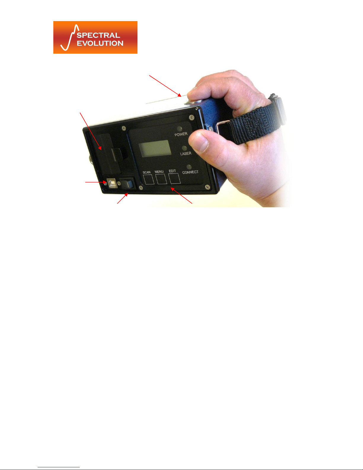
Li-Ion
On/Off Switch
Control Panel
Las
er Scan Switch
Battery
USB
Connector
PSR-1100 Manual
Revision: 1.00
4/5/2012
Figure 1: Front Panel view of the PSR-1100
2.1.5 Front Panel
The front panel of the PSR-1100 contains the on/off switch, USB connector,
battery receptacle and a control panel with membrane switches and LCD display. A
handstrap is permanently attached and near the front panel are two mounting brackets
for attaching a shoulder strap. See Section 3: Control Panel for more information.
2.1.6 Back Panel
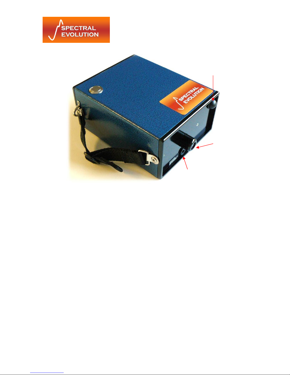
The opposite end of the PSR-1100 contains the optical input (lens or SMA fiber
optic input), Bluetooth antenna and optional tripod mount.
2.1.7 Laser Scan Switch
The Laser Scan switch is located on the top cover of the spectroradiometer.
Depressing the switch actuates the sighting laser and can be optionally configured to
initiate the start of a standalone spectral scan.
DANGER: DO NOT LOOK INTO THE LASER BEAM AT ANY TIME, INCLUDING
INSTRUMENT SETUP OR OPERATION.
For more information see Appendix A: Laser Safety.
©2012 Spectral Evolution Inc. 90 Sutton St. Unit 4, North Andover, MA 01845 USA
6
Page 7
PSR-1100 Manual
Revision: 1.00
4/5/2012
Bluetooth
Antenna
Lens
Laser
Figure 2: View of PSR-1100 optical components
2.2 Interface Specification
2.2.1 Battery Pack
Your PSR-1100 is supplied with one or more Li-Ion battery packs that fit into the
recess on the front panel. Slide the spring-loaded catch to the side (away from the
recess) with a finger to insert or remove the battery.
Important: See Section 0:
©2012 Spectral Evolution Inc. 90 Sutton St. Unit 4, North Andover, MA 01845 USA
7
Page 8

PSR-1100 Manual
Revision: 1.00
4/5/2012
Battery Charger for details on charging the external battery and safe operation.
2.2.2 USB Serial Connector
For communications via USB, the front panel is equipped with a USB Type-B
receptacle connector, compatible with all standard USB cables with Type-B plug.
Pin 1: +5V
Pin 2: D Pin 3: D+
Pin 4: GND
2.2.3 Serial Communications via USB or Bluetooth Virtual COM Port
Baud Rate: 115200 bps
Parity: none
Data Length: 8
Stop bit: 1
Flow Control: none
2.2.4 ESD protection:
+/- 15 KEV human body model,
+/- 8KEV contact discharge
©2012 Spectral Evolution Inc. 90 Sutton St. Unit 4, North Andover, MA 01845 USA
8
Page 9

PSR-1100 Manual
Revision: 1.00
4/5/2012
3 Control Panel
The control panel of each PSR-series spectroradiometer contains the controls
and displays that are required for the stand-alone operation of the instrument.
3.1 Indicators
The Control Panel has 3 LED status indicators.
Power LED: The power indicator is illuminated when the power is on.
Laser LED: The laser indicator is illuminated when the laser is on.
Connect LED: The connect indicator is illuminated when the instrument is NOT
connected to a computer via Bluetooth communication link.
3.2 Switches
3.2.1 Power Switch
The power switch provides on/off control of the unit.
3.2.2 Membrane Switches
The three (3) membrane push button switches provide control of the unit during
standalone operation and the capability of modifying the unit’s operation. The functions
of the switches are detailed below.
3.2.3 Switch Function
Scan: Steps through scan options (Reference/Target/Dark Scans)
Menu: Steps through the menu options (Memory Scan#/Dark Scan Mode/Scan
Timer/Optic/Laser Scanning)
Edit: Toggles or cycles through parameter lists for each menu option
3.3 LCD Display
The LCD display is an eight (8) character, two (2) row display that shows the selected
scan and status messages.
ROW 1 displays the scan types, status messages, and battery voltage. The SCAN
button allows the user to select the type of scan to perform.
ROW 2 displays the parameter menu. The MENU button allows the user to scroll
through a set of available parameters, and the EDIT button changes the parameter
settings.
3.3.1 Scan Types
The next type of scan to be collected is displayed in row 1 as follows:
©2012 Spectral Evolution Inc. 90 Sutton St. Unit 4, North Andover, MA 01845 USA
9
Page 10

PSR-1100 Manual
Revision: 1.00
4/5/2012
REF x.xx - Indicates that a spectral measurement will be stored as a Reference Scan;
current battery voltage is x.xx volts, or “LBAT” (Low BATtery) when indicated.
TAR x.xx - Indicates that a spectral measurement will be stored as a Target Scan;
current battery voltage is x.xx volts, or “LBAT” (Low BATtery) when indicated.
DRK x.xx - Indicates that a dark measurement will be acquired. The dark measurement
will be stored in volatile memory (not flash) and used for subsequent scaled dark
measurements. The current battery voltage is x.xx volts, or “LBAT” (Low BATtery) when
indicated.
Pressing the SCAN button cycles through these options. Note that after a REF scan is
taken, the instrument automatically switches to collecting TAR scans.
3.3.2 Status Messages
These messages are also displayed on row 1:
SCANNING - Indicates that a spectral data acquisition is being performed.
BUSY - Indicates that the instrument is performing a lengthy internal operation.
3.3.3 Parameter Menu
The parameter menu is displayed on row 2. The MENU button allows the user to cycle
through the following parameters. The EDIT button changes the parameter values.
MEM# xxx - Displays the memory slot that will hold the next acquired scan. The
allowable values are from 1 to 500. The memory slot cannot be adjusted by the keypad,
with the exception of completely erasing all memory.
To erase all memory and set MEM# to one (1), the <MENU> and <EDIT> keys must be
pressed simultaneously. IMPORTANT! This operation permanently erases all internally
stored scans taken in standalone operation mode.
DRK xxxx - Selects the dark subtraction mode:
AUTO - Automatic Dark mode is selected. Dark current measurement will be acquired
automatically prior to each scan. The dark currents will be acquired at the same settings
as the target scan.
SCLD - Scaled Dark mode is selected. Dark Current for each scan will be scaled, based
on the integration time and the Dark Scan that was acquired manually using the Dark
scan.
STIM xxx - STIM xxx is the scan averaging time. The allowable values are from 1 to 30.
The length of time for a scan is xxx seconds, for each light and dark scan.
O:xxxxxx - Entrance optic option. This must be set to the entrance optic in use for
correct calibration factors to be applied. There can be up to eight (8) optic calibration
options stored in a single instrument. Some possibilities are listed below:
(1) LENS 4 – 4 degree FOV lens
(2) FIBER1 – standard 25 degree FOV fiber optic
©2012 Spectral Evolution Inc. 90 Sutton St. Unit 4, North Andover, MA 01845 USA
10
Page 11

PSR-1100 Manual
Revision: 1.00
4/5/2012
(3) LENS14 – 14 degree FOV lens
(4) RAW DN – no calibration applied
LSCN xxx - Laser Scan Switch function. This can be set to ON or OFF. When the Laser
Switch is depressed, the sighting laser is (always) turned on. When LSCN is set to ON, a
stand alone scan will be acquired when the switch is released. When LSCN is set to
OFF, no scan will be acquired.
3.3.4 Modifying a Parameter
(1) Depress the MENU button to locate the parameter you wish to edit.
(2) Modify the parameter by depressing the EDIT button. The push button switches are
programmed to scroll the menu of available options.
(3) Depress the MENU button again to save the selected parameter setting.
©2012 Spectral Evolution Inc. 90 Sutton St. Unit 4, North Andover, MA 01845 USA
11
Page 12

PSR-1100 Manual
Revision: 1.00
4/5/2012
4 Operational/Functional Description
All Spectral Evolution PSR series spectroradiometers operate as portable field
instruments with onboard data storage and an easy-to-use manual control panel for
standalone operation. Combined with a host PC, the PSR can also be controlled for
acquisition in real time and for retrieval and display of the stored scan data.
4.1 Setup
To use the PSR-1100, install a fully charged battery pack by inserting it into the battery
slot located on the instrument’s front panel. Switch the power switch to the ON position.
After a brief initial power-on period, the LCD indicator will display the message “REF”
followed by a battery voltage reading and “O: LENS4”.
4.2 Standalone Operation
Dark Measurement Overview
A dark measurement must be taken prior to taking reference or target
measurements. Dark measurements are taken automatically by the instrument in
AutoDark Mode, or are taken manually by the operator when in Scaled Dark Modes.
In AutoDark Mode, the internal shutter automatically closes and dark
measurement taken immediately prior to the reference or target scan; there is no need to
ever take a dark measurement manually.
If Scaled Dark Mode is used, however, a dark measurement must be taken
manually. A new dark measurement should taken periodically, more often under
changing environmental conditions.
Using AutoDark Mode ensures that the latest dark values are subtracted on
every scan; however, enabling AutoDark doubles the amount of time the scan requires
to complete. The dark measurement is subtracted from the Reference and Target
measurements. Dark measurements are stored in the PSR’s RAM and are not saved
when the power is cycled.
Reflectance Measurement Overview
A reflectance measurement takes the scan of a reference (white plate) and
calculates the ratio of the target scan to that reference. Unless the instrument is set to
AutoDark Mode (where it takes a new dark reading with every scan) - if any of the below
conditions exist, a new dark measurement should be taken:
• After instrument power-up and warm-up, but before acquiring any reference/target
scans.
• Every 3-5 minutes thereafter; more often if time and conditions allow, or if lighting
or environmental conditions are changing.
If any of the below conditions exist, a new reference measurement should be
taken before a series of target measurements:
• Beginning of a new set of scans.
• Any change in the collection optics.
• The instrument has been idle for an extended period, or has been turned off.
©2012 Spectral Evolution Inc. 90 Sutton St. Unit 4, North Andover, MA 01845 USA
12
Page 13

PSR-1100 Manual
Revision: 1.00
4/5/2012
• Lighting conditions have changed or are variable.
When in doubt, take a reference measurement!
Taking a DARK Measurement (Skip these steps in AutoDark Mode)
1. Check that the LED Power Indicator is illuminated, indicating that the power is
enabled.
2. Press the Menu membrane switch unit the LSCN menu item appears; press the Edit
membrane switch so that ON appears.
3. Press the Menu membrane switch until the DRK menu item appears; press the Edit
membrane switch so that SCLD appears. This enables the Scaled Dark Mode for
standalone operation.
4. Press the Scan membrane switch until the DRK x.xx scan message appears on the
LCD. (x.xx indicates battery voltage) Check to see if battery is adequately charged.
5. Press and release the Laser Scan button on the side of the unit. The instrument will
close the shutter and take dark data for approximately 15 seconds. Since the shutter
closes in order to take the dark measurement, no particular target needs to be sighted
by the instrument optics during a dark measurement. Dark measurements do not take up
a memory location within the instrument’s stand-alone scan memory.
6. The dark measurement just taken is associated with all succeeding measurements
until a new Dark measurement is established. Dark measurements are stored in volatile
memory (not flash) and must be retaken whenever the instrument power is cycled.
Taking a REFERENCE Measurement
1. Check that the LED Power Indicator is illuminated, indicating that the power is
enabled.
2. Press the Menu membrane switch unit the LSCN menu item appears; press the Edit
membrane switch so that ON appears.
3. Press the Scan membrane switch until the REF x.xx scan message on the LCD. (x.xx
indicates battery voltage) Check to see if battery is adequately charged.
4. Place a reference at the point of measurement making sure to completely fill the field
of view of the instrument. This reference measurement is associated with all succeeding
measurements until a new reference measurement is established.
5. Press and hold the Laser Scan button to activate the sighting laser and verify the
placement of the reference plate relative to the laser spot as required to fill the field of
view.
6. Release the Laser Scan button to record the measurement. The LCD counter
increments to display the next available memory location.
Taking a TARGET Measurement
1. Check that the LED Power Indicator is illuminated indicating that the power is enabled.
2. Press the Menu membrane switch until the LSCN menu item appears; press the Edit
membrane switch so that ON appears.
3. Press the Scan membrane switch until the TAR x.xx scan message on the LCD. (x.xx
indicates battery voltage) Check to see if battery is properly charged.
4. Place a reference at the point of measurement making sure to completely fill the field
of view of the instrument. This reference measurement is associated with all succeeding
measurements until a new reference measurement is established.
©2012 Spectral Evolution Inc. 90 Sutton St. Unit 4, North Andover, MA 01845 USA
13
Page 14

PSR-1100 Manual
Revision: 1.00
4/5/2012
5. Press and hold the Laser Scan button to activate the sighting laser and verify the
placement of the target to be measured relative to the laser spot as required to fill the
field of view.
6. Release the Laser Scan button to record the measurement. The LCD counter
increments to display the next available memory location. Additional target
measurements may be made by pressing and releasing the Laser Scan switch.
4.3 Operation with a host PC
The PSR-1100 interacts with Spectral Evolution’s DARWin SP software
(provided with your instrument) running on the host PC via USB or Bluetooth virtual
COM port connection.
The primary tasks that can be performed by running DARWin SP while
connected to your spectroradiometer are:
1. Controlling the instrument remotely and collecting and displaying scan data in
real time, with expanded control options, and
2. Retrieving and displaying scan data collected and stored during standalone
operation.
Be sure to install the software (and any USB/Bluetooth communications drivers
as needed) prior to the first time you connect to the instrument.
When running DARWin SP make sure your instrument has a charged battery and
that it is powered and that the proper communications interface has been enabled. Once
communications have been established, a brief initialization sequence follows and then
your system is ready for use.
For detailed information on how to use DARWin SP with your PSR Series
spectroradiometer, see the DARWin SP User Manual included with your instrument.
©2012 Spectral Evolution Inc. 90 Sutton St. Unit 4, North Andover, MA 01845 USA
14
Page 15

PSR-1100 Manual
Revision: 1.00
4/5/2012
5 Battery Charger
5.1 Introduction
The provided battery charger is used to charge one lithium-ion battery (nominal
7.5VDC, 2800 mA-h). The charger operates from 110/240 volt AC line supply. Follow all
directions for proper, safe operations. Only charge batteries indoors in a cool place.
5.2 Operation
To charge the external battery pack:
1. Remove the battery pack from the instrument.
2. Plug the charger’s round male plug into the battery pack’s female jack.
3. Plug the charger into an AC outlet.
The charger’s RED LED will be illuminated during charging; when charging is complete
the charger’s GREEN LED will be illuminated.
Charging a battery from empty to full capacity (approximately 8.4VDC) will take
approximately 2-3 hours.
5.3 Information and Warnings
Cells: 18650 Li-ION cells with IC protection are used inside the battery pack
Protection: 4A max polyswitch is installed in the battery pack for double over-discharging
protection.
The battery will be automatically cut off to zero (0) volts when its voltage falls too low for
PSR operation.
WARNINGS:
• Avoid heavy impact to the battery pack; this may cause the battery pack to
malfunction.
• Do not expose the battery pack to fire or extreme heat; this may cause the
battery pack to malfunction.
• Do not use any DC power supply or charger other than the dedicated battery
charger supplied with your instrument; this may cause the battery pack to
malfunction.
Also, always power the PSR Series instrument with its battery only. NEVER use the
dedicated battery charger to provide power to the instrument.
©2012 Spectral Evolution Inc. 90 Sutton St. Unit 4, North Andover, MA 01845 USA
15
Page 16

PSR-1100 Manual
Revision: 1.00
4/5/2012
Appendix A: Laser Safety
The PSR Series Spectroradiometers use a Class 3R laser beam that complies with IEC
60825-1, Ed. 1.2. The source of laser energy in the PSR is a nominal 3 mw, continuous,
635 nm diode laser. No maintenance or adjustments are required in order to keep this
product in compliance with the above specifications.
DANGER:
Do not look into the laser beam at any time including instrument setup or
operation.
The laser is operated by pressing the Laser Scan Switch located on the top surface of
the instrument. See Section 2: Hardware and Interface Description for the location of
this control.
CAUTION - Use of controls or adjustments or performance of procedures other
than those specified herein may result in hazardous radiation exposure.
There are no user serviceable components within this device. The unit should be
returned to the manufacturer in case of malfunction.
LABELING:
The following labels are required for the PSR Series instrument. Each label is described
below. If the instrument does not have the appropriate labels, contact the manufacturer
to ensure that your unit is in compliance.
(1) Explanatory Label
Location – Bottom of instrument, on the product information label.
(2) Supplementary Explanatory Label
Laser Power: 3 mW, Laser Wavelength 635 nm.
Laser conforms to IEC 60825-1, Ed 1.2.
Location – Bottom of instrument, on the product information label.
(3) Warning Label
Location – Bottom of instrument, on the product information label
©2012 Spectral Evolution Inc. 90 Sutton St. Unit 4, North Andover, MA 01845 USA
16
Page 17

(4) Aperture Label
Location - Next to the laser aperture.
PSR-1100 Manual
Revision: 1.00
4/5/2012
©2012 Spectral Evolution Inc. 90 Sutton St. Unit 4, North Andover, MA 01845 USA
17
Page 18

Appendix B: PSR-1100 Specifications
Performance Specifications
Spectral Range 320–1100 nm
Spectral Resolution
nominal
Spectral Sampling Bandwidth
nominal
Detector 512 element Si PDA
A/D Converter 16 bit
Wavelength Accuracy .5 nm
Wavelength Reproducibility .1 nm
Integration Time 8-2000 ms
Physical Specifications
Power
Size 7” x 3.25” x 5.75”
Weight < 4 lbs
Communications Interface USB and Bluetooth virtual COM ports
Foreoptics 4° lens provided (other options available)
Onboard Storage > 500 scans in stand-alone mode
Targeting Internal red laser
Environmental Specifications
Operation
Temperature 15 - 35° C (note: wvl drift 18 - 27° C)
Humidity 15 – 90 % non - condensing
Storage
Temperature 0 - 70° C
Humidity 15 – 90 % non - condensing
Supplied 2800 mA-h Li-Ion battery pack with
<= 3.2 nm
1.5 nm
charger, 7.5V nominal
PSR-1100 Manual
Revision: 1.00
4/5/2012
©2012 Spectral Evolution Inc. 90 Sutton St. Unit 4, North Andover, MA 01845 USA
18
Page 19

PSR-1100 Manual
Revision: 1.00
Appendix C: Bluetooth Information
Bluetooth Versions Supported: V1.1
Bluetooth Class: Class I
Bluetooth Connection Type: Virtual COM Port
Bluetooth Connection Pin Key/Pairing Code: psr1100
Revision
Tracking
1.0 Original Draft 4/5/11
Windows
®
is a registered trademark of Microsoft Corporation.
Changes Date
4/5/2012
©2012 Spectral Evolution Inc. 90 Sutton St. Unit 4, North Andover, MA 01845 USA
19
 Loading...