

Spectral Audio ProTone User Manual

Page 1
3
52
7RQH
MIDI Analog Synthesizer
Operating Instructions
-
Bedienungsanleitung

Page 2
1.
Introduction..................................................................................................................... 3
2.
Notes on Operation ........................................................................................................ 3
3.
Guarantee........................................................................................................................ 3
4.
Description of the Operating Elements......................................................................... 4
4.1 Sockets on the Rear of the Housing .............................................................................. 4
4.2 Front Panel Controls...................................................................................................... 5
5.
Functional Description ................................................................................................... 6
5.1 Subtractive Synthesis (Theory)...................................................................................... 8
6.
Start-up............................................................................................................................ 9
7.
Troubleshooting ............................................................................................................. 9
8.
MIDI Functions..............................................................................................................10
8.1 Learn Mode ................................................................................................................. 10
8.2 General........................................................................................................................ 11
8.3 Legato Play Mode........................................................................................................ 11
8.4 Re-trigger .................................................................................................................... 11
8.5 Volume and Filter Dynamic Operation ......................................................................... 11
9.
Modifications ................................................................................................................ 12
9.1 Changing the CV and Gate Input / Output ................................................................... 12
9.2 Increasing the Gate Voltage to +12V...........................................................................12
9.3 Changing the Operating Voltage ................................................................................. 12
10. Thermal Characteristics / Octave Purity ..................................................................... 13
11. Glossary ........................................................................................................................ 14
12. Technical Data .............................................................................................................. 15
13. Sounds ..........................................................................................................................15
14. Einleitung ...................................................................................................................... 16
15. Betriebshinweise .......................................................................................................... 16
16. Garantie.........................................................................................................................16
17. Erklärungen zu den Bedienungselementen................................................................ 17
Buchsen auf der Gehäuserückseite: ..................................................................................... 18
18. Funktionserklärung ...................................................................................................... 18
19. Inbetriebnahme ............................................................................................................. 21
20. Fehlersuche................................................................................................................... 22
21. MIDI Funktionen............................................................................................................ 22
21.1 Learnmodus .............................................................................................................22
21.2 Allgemeines.............................................................................................................. 24
21.3 Legato-Spiel ............................................................................................................. 24
21.4 Retrigger .................................................................................................................. 24
21.5 Volume- und Filterdynamischer Betrieb.................................................................... 24
22. Modifikationen .............................................................................................................. 24
22.1 Änderung der CV- und Gate Ein-/Ausgänge............................................................. 24
22.2 Erhöhung der Gatespannung auf +12 V................................................................... 25
22.3 Äderung der Betriebsspannung................................................................................ 25
23. Lexikon..........................................................................................................................25
24. Technische Daten ......................................................................................................... 26
25. Sounds ..........................................................................................................................27

Page 3
1. Introduction
Why an Analog Synthesizer?
Why are analog synthesizers being built again? We come across this question time and again.
More than 10 years ago, the analog synthesizer technique fell to the wayside. The reason why
this old technique is being revived is easy to demonstrate.
Above all, the 'Techno-Boom' has increased the demand for special, never heard before sounds.
When we consider that the old analog synthesizers had such a special and powerful sound, as
well as the fact that access to editing parameters is much faster and more efficient by means of
slide and rotary regulators than via a display with menu parameters, then the question is already
answered.
In order to use the ProTone professionally, we recommend that the following chapters are read
through carefully.
We wish you much fun with the ProTone!
2. Notes on Operation
The equipment is only intended for use as described in these operating instructions. It must only
be used in a dry environment. No liquids must enter the equipment. If this should however
happen, it must be cleaned by a professional.
Do not expose the equipment to direct sunlight. Do not operate the equipment in the vicinty of a
radiator or any other heat source. Do not expose the equipment to any temperatures above 50
degrees Celcius or below 10 degrees Celcius. Transport the equipment with care.
Only use the original packaging to send the unit back to us for repair under guarantee, software
update, etc. Other deliveries may not be accepted because of possible transport damage. For
this purpose, always keep the original packaging.
3.
Guarantee
The equipment is guaranteed against manufacturing defects for a period of one year from the
date of purchase. Normal signs of wear are excepted. In the event of manipulations or
modifications which have been carried out incorrectly, any claims under guarantee are
immediately void.
Page 4
Out
Left
Out
Right
Extern
VCO
Input
Extern
LFO
Input
GateCVMIDI
Thru
MIDI
IN
0.7 Veff
0.7 Veff
0V:Off
1V/Oct
5V:On
230 V~
max. 500mAT
3UR7RQH
Made in Switzerland
373638394041424344
Warning : Shock Hazard - do not open!
Vorsicht : Lebensgefahr - nicht öffnen!
Avis : Risque de choc Electrique - ne pas ouvrir!
63(&75$/$8',2*PE+
Serial No.
4.
Description of the Operating Elements
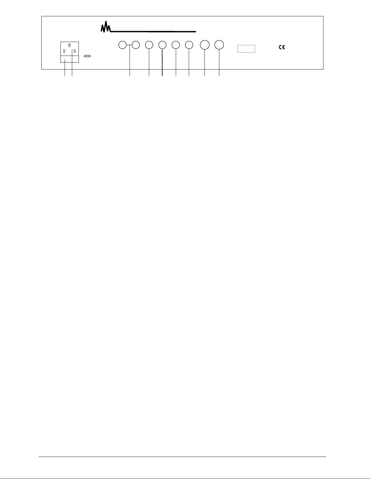
4.1 Sockets on the Rear of the Housing
36. Power socket
37. Fuse compartment, fuse max. 500 mA, 250V type
38. Audio outputs right / left
39. External VCO input, switched on with switch (7)
40. External modulation input, selected with selector switch (22)
41. Gate input/output (dependent on the jumper setting inside the unit, standard setting: output)
42. CV input / output (dependent on the jumper setting inside the unit, standard setting: output)
43. MIDI Thru socket
44. MIDI IN socket
Page 5
781(3:12,6(
781(
6/,'(
(;7
9&2
9&2
),/7(5
.(<
)2//2:
/)2
)5(48(1&<
02'8/$7,21
:$9(
/)221
12,6(
(;7
3:
9&2
9&2
3$1
5$1'20
5$1*(
0,''/(
/2:
+,*+
3UR7RQH
*$7(
/($51
32:(5
*5281'
/(9(/
/($51
3$1
(1902'
&872))
5(621$1=
92/9&2
5,1*02'
92/9&2
'(&$<
$77$&.
6867$,1
5(/($6(
&87
2))
$&&(17
G%
+,*+3$66
/2:3$66
G%
6<1&210,',$1$/2*6<17+(6,=(5
-6542112307891011654211230789101165421123078910116542112307891011654211230789101165421123078910116542112307891011654211230789101165421123078910116542112307891011654211230789101165421123078910116542112307891011654211230789101165421123078910116542112307891011C1RL54325143
2
0166543251432-+016654325143
2-+1012345678911141012131819151617252627202122232428293130323334
35
63(&75$/$8',2
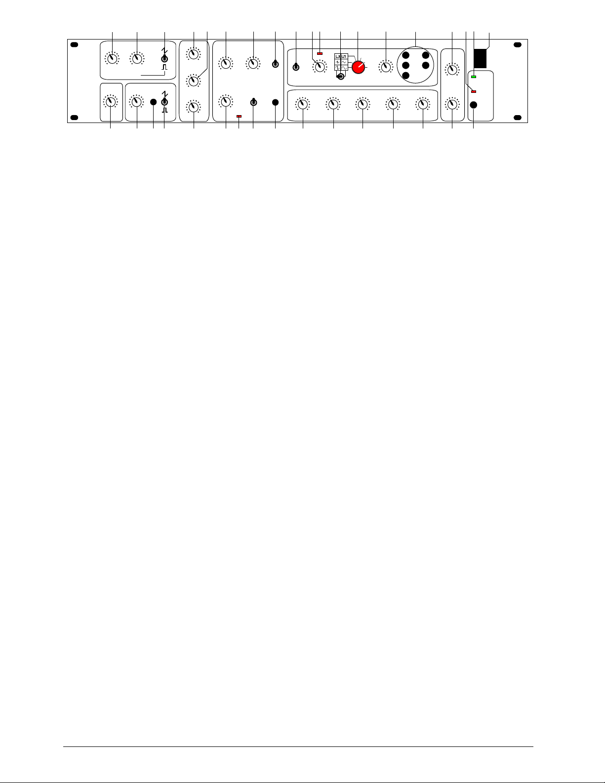
4.2 Front Panel Controls
VCO 1:
1. TUNE: Regulates the pitch of the VCO 1
2. PW: Pulse width of the rectangular pulse
3. Changeover between the signal types sawtooth, noise and rectangle
4. SLIDE: regulates the time balance of VCO 1 and VCO 2
VCO 2:
5. TUNE: Regulates the pitch of the VCO 2
6. SYNC: Synchronises VCO 2 with VCO 1
7. Changeover between the signal types sawtooth, external (input on rear of housing) and rectangle
Mixer:
8. VOL VCO 1: Volume of VCO 1
9. RINGMOD: Volume of the ring modulation of VCO1 and VCO2
10. VOL VCO 2: Volume of VCO 2
VCF:
11. CUTOFF: Cut-off frequency of the filter
12. RESONANCE: increases the harmonics at the cut-off point
13. Changeover between lowpass and highpass
14. ACCENT: Pulsed increase of the cut-off frequency and the volume
15. ACCENT ON Indicator: Lights when the accent function is switched on (MIDI Controller 65)
16. Determines the edge steepness of the filter: 12 or 24dB / octave
17. KEYFOLLOW: The cut-off frequency is influenced by the actual note
LFO:
18. RANGE: Changeover between three LFO frequency ranges
19. FREQUENCY: Setting the LFO frequency
20. LFO Indicator: Indicates each positive halfwave of the LFO.
Note:
The eye recognises frequencies larger than 60 Hz as being static.
21. Changeover between symetrical and asymetrical LFO waveforms
22. Selector switch for different LFO waveforms. By means of the matrix presentation, there are a total of 9
signal forms available: sinus, asymetrical sinus, triangle, sawtooth, rectangle, pulse, random, noise and
external (input on the rear of the housing)
23. MODULATION: Determines the strength of the LFO influence
24. LFO ON..: LFO assignment possibilities: VCO 1, VCO 2, PW 1, cut-off, pan (any combination possible)
Envelope:
25. ATTACK: Rise time
26. DECAY: Decay time
27. SUSTAIN: Hold level
28. RELEASE: Release time
29. ENV MOD: Influences the cut-off frequency with the envelope
Stereo VCA:
30. GROUNDLEVEL: Ground level of the unit. This also includes the volume increase influenced by the
accent.
31. PAN: Regulates the relationship of the volume from the left and right-hand channel

Page 6
Various:
32. LEARN Key; Switches the ProTone to the learn mode
33. GATE / LEARN indicator
34. Switch-on indicator
35. Main switch
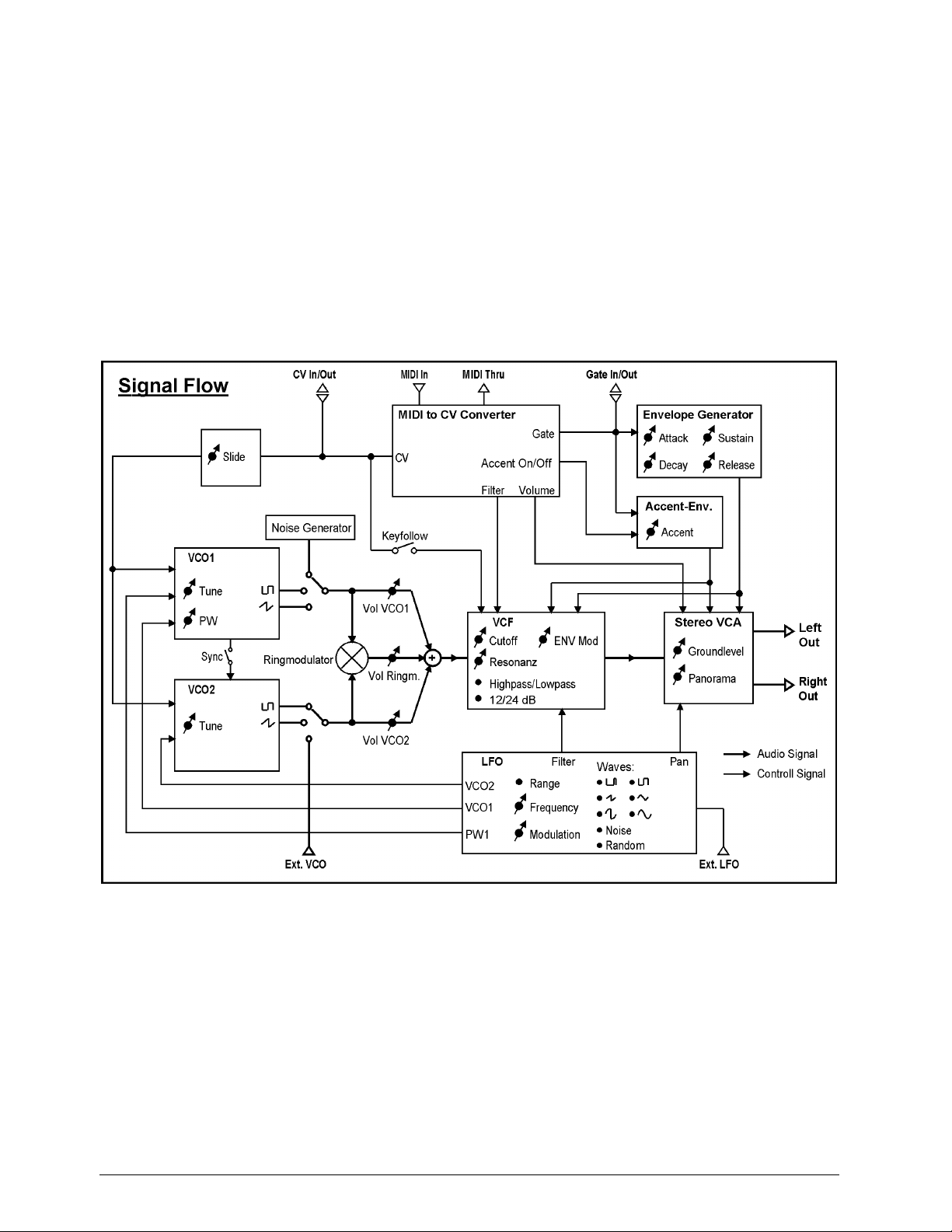
5.
Functional Description
The basic principle of the ProTone corresponds to the tried and tested analog synthesizer principle with
VCO, VCF, VCA, envelope generator and LFO. This principle is called subtractive synthesis.
In order that the ProTone is suitable for MIDI, an additional MIDI to CV converter is necessary which
converts the MIDI signals into analog signals with which the VCOs, the filter, as well as the envelope
generator are controlled.
The raw material for the sound is offered by the VCOs (Voltage Controlled Oscillator) in the form of a
sawtooth or rectangular signal as well as the noise generator (for effects such as wind and thunder
sounds). The width of the rectangular signal from VCO1 can be changed with the PW regulator (2). The
narrower the rectangular signal (regulator turned to the right), the 'sharper' the sound. VCO2 is
synchronised from VCO1 with the SYNC switch (6). The tone will be interesting in this case when the TUNE
regulator (5) of VCO2 is turned (or by modulating with the LFO VCO 2), which results in a typical "SyncSound".
By means of the external VCO input, other sounds can also serve as raw material. The ring modulator
multiplies the signals of the two VCOs which markedly amplifies the beat (frequency difference).
Note:
When the SYNC switch (6) is switched on, no beats are developed and the ring modulator has
therefore no effect.
The SLIDE regulator (4) determines the time balance from one note to another and is valid for both VCOs.
Afterwards, the signal flows through the voltage controlled filter (VCF=Voltage Controlled Filter), within
which certain frequency ranges are suppressed. The lowpass filter allows low frequencies to pass and
suppresses the high ones, the highpass filter lets high frequencies through and suppresses the low ones.
The frequency from which the signals are suppressed is called the limit or cut-off frequency. With the
ProTone, this is formed from various sources:
1. CUTOFF frequency regulator (11)
2. ENV MOD regulator (29) (influence of the envelope on the cut-off frequency)
3. LFO
4. ACCENT regulator (14)
5. KEYFOLLOW switch (17).
With the KEYFOLLOW switch (17), the cut-off frequency increases on higher notes so that audible
freqency bands always remain the same. The resonance forms a feedback of the output to the input of the
filter and causes an amplification of the frequencies around the cut-off frequency.
The ACCENT regulator (14) sets the share of the second envelope and affects the cut-off frequency as well
as the volume. It is only active when the ACCENT indicator (15) lights, ie, when the accent function is
switched on via the MIDI controller 65. The accent function is always active when the unit is switched on. By
means of the MIDI controller 65, it is now possible, as with the TB 303, to give individual notes an accent
(value 127) or to take an accent away (value 0). For this purpose, the corresponding control value must be
sent in the sequencer, timed either before or with the note.
Before the signal leaves the ProTone, it arrives at the VCA (Voltage Controlled Amplifier) which is available
in the ProTone in stereo form. Here the input signal is multiplied with a control signal. In this way, the
volume can be influenced by a control signal which comes from the envelope generator and the MIDI
converter. The volume of the ProTone is controlled with the GROUND LEVEL regulator (30) as well as via
the MIDI controller EXT (7). Additional to this level is the short-term increase through the accent function.
The panorama (volume relationship of the left-hand to the right-hand signal) can be set with the PAN
regulator (31).
Page 7
The LFO is particularly developed with the ProTone. Using its signal, the pitch from VCO1 and VCO2, the
pulse width of the rectangular signal from VCO1, the cut-off frequency of the filter as well as the panorama
can be modulated with the LFO ON ... switches (24).
With switches (21) and (22) selection can be made between 9 different signal forms. By means of the
external LFO input on the rear of the housing, it is also possible to use any other signal for modulation. To
do this, switch (22) must be turned completely to the right. A microphone, etc, must be connected via a preamplifier as this is a high level input. When the external inputs of the ProTone are used, the ProTone must
simultaneously receive a note command (the same MIDI channel) in order that something is audible.
The envelope generator determines the chronological sequence of the volume after receiving a note
command. The MIDI to CV converter then gives out a gate signal (+5V) with which the sequence of the
envelope generator begins. The gate signal remains at +5V until the 'note off' command comes, ie, the key
is released. The parameters of the envelope can be set with regulators (25) to (28). How the envelope
should be imagined is described later on in the glossary.
Page 8
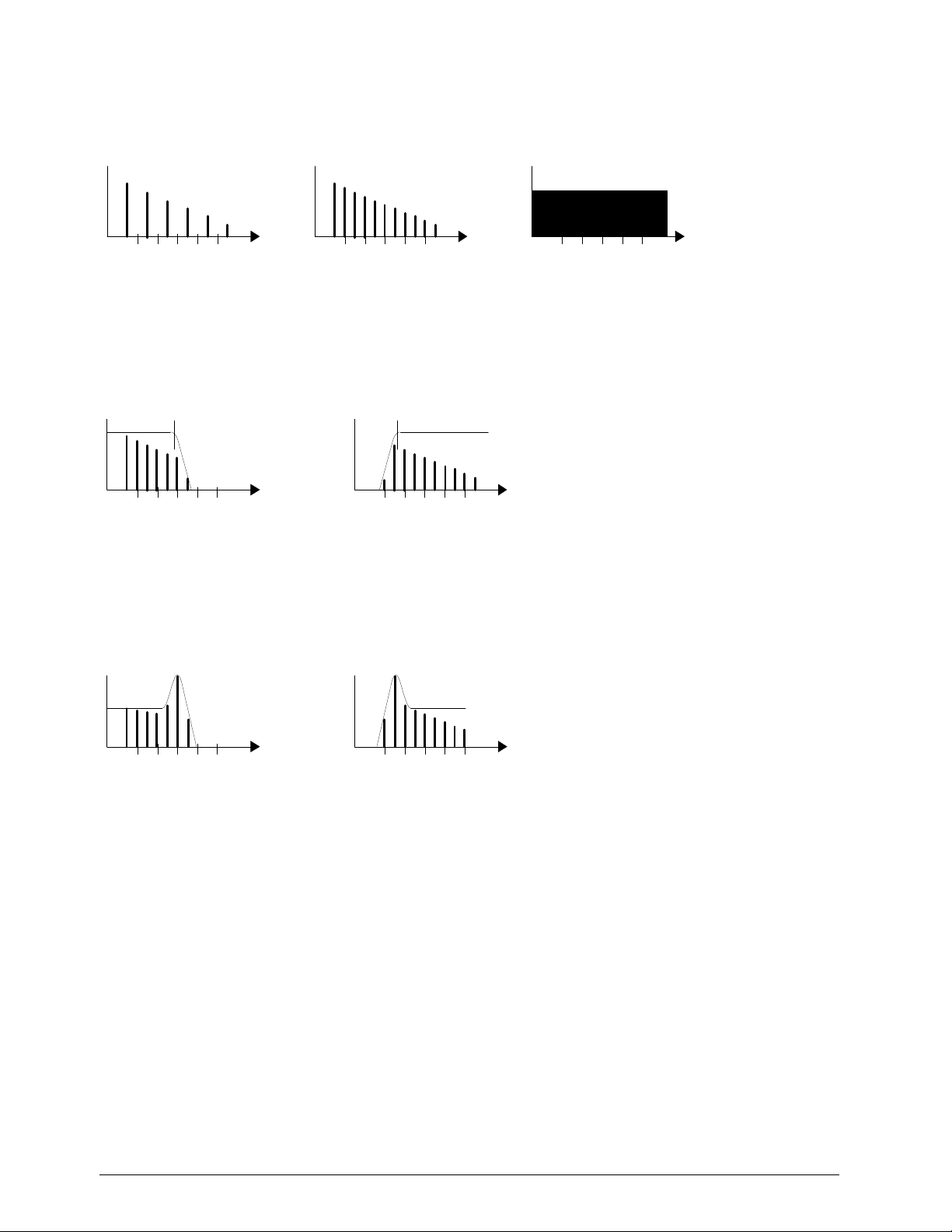
5.1 Subtractive Synthesis (Theory)
The VCOs produce very harmonic rectangular and sawtooth signals:
Frequency
1357911Pulse (50%):
1357911Saw:
1357911Noise:
Frequency
Frequency
Noise contains an endless number of frequencies. This frequency spectrum is subsequently limited by the
filter:
1357911Lowpass Filter:
1357911Highpass Filter:
Cutoff Frequency
Cutoff Frequency
Frequency
Frequency
The setting of the resonance regulator is an important factor as it amplifies the frequencies around the cutoff frequency:
13579111357911Highpass Filter with
high Resonance:
Lowpass Filter with
high Resonance:
Frequency
Frequency

Page 9
6.
Start-up
1. Connect the MIDI IN socket (44) on the ProTone to your MIDI sender (master keyboard, sequencer, ...)
via a MIDI cable. If further MIDI units come after the ProTone, connect the MIDI Thru socket (43) to the
MIDI IN socket of the next equipment by means of a further MIDI cable.
2. Connect the right and left audio outputs (Out Right and Out Left) with the audio input of your sound
mixer, amplifier or similar equipment.
3. Connect the mains cable.
4. If you are not familiar with analog synthesizers and are about to use the ProTone for the first time,
position all regulators and switches on the front of the unit to the base settings or in a sound setting in
accordance with one of the diagrams given at the back of these instructions.
5. Switch on the ProTone. The GATE / LEARN indicator (33) must light briefly. The POWER indicator (34)
and the ACCENT indicator (15) must light. If you now play on your MIDI keyboard and have selected the
correct MIDI channel and reference sound (see para. 5, MIDI Functions), then you should already be
able to hear something. If this is not the case, please refer to para. 4, Troubleshooting. For the first startup, the ProTone is set to MIDI channel 1.
7.
Troubleshooting
1. Does the POWER indicator (34) light ?
No : - Equipment is not switched on
- Power supply connection faulty
- Fuse defective
Yes : Continue with 2.
2. Does the GATE/LEARN indicator (33) light when you play your MIDI keyboard ?
No : - The MIDI channel does not correspond with the MIDI keyboard. Set the MIDI channel and
reference sound as described in para. 5, MIDI Functions.
- MIDI connection faulty / not correct
Yes : - Connection to sound mixer not correct
- Basic setting not carried out correctly
- Sound mixer not set correctly

Page 10
8.
MIDI Functions
In the
normal operating mode
, the following MIDI commands are processed:
Note On/Off : In the range from the reference note up to a maximum of 5 octaves above it .
Pitch Bend : Control of the pitch
Controller X : Control of the cut-off frequency
Controller 7 : Regulates the volume (ground level)
Controller 64: Controls the hold function (sustain): On = data value 127; Off = data value 0)
Controller 65: Switches the accent function on/off: On = data value 127; Off = data value 0)
All these commands are of course only received on a MIDI channel which has been defined in the Learn
mode. In the normal operating mode, the GATE/LEARN indicator (33) shows the gate function.
8.1 Learn Mode
The Learn mode is accessed by pressing the LEARN key (32) and is indicated by the blinking
GATE/LEARN indicator (33). In this mode, MIDI parameters such as reference note and controller X are
determined. In the Learn mode, the following MIDI commands are significant.
After receiving one of these MIDI commands, the GATE/LEARN indicator (33) goes off and the ProTone
goes into the normal operating mode. If several parameters are to be changed, then the Learn mode must
be selected several times. The parameters set are not lost when the unit is switched off.
8.1.1 Note-On Command (key is pressed):
The MIDI channel of the incoming note command is accepted as the new MIDI receive channel (=
MIDI
channel setting
). The pitch (MIDI note number) is accepted as the
reference note
for the lowest possible
tone (=transport function). On the sequencer, select the channel on which it is intended to have the
ProTone, press the LEARN key (32) on the ProTone and activate the lowest key on the master keyboard.
The absolute pitch is dependent on the setting of the tune regulators (1) and (5).
8.1.2 Controller Command (for Controller X):
The number of the first incoming controller will be used as future controller number for control of the cut-off
frequency. On the sequencer, select the channel for the ProTone, press the LEARN key (32) on the
ProTone and activate, for example, the modulation wheel of the master keyboard.
8.1.3 Program Change Command:
With this command, the linking of the controller data and velocity can be determined for the ProTone.
Furthermore, the re-trigger function can be switched on/off:
Program #1 (Standard)
- Volume dynamic operation is switched off
- The Legato play mode is allowed (switched on)
Program #2
- Volume dynamic operation is switched on
- The Legato play mode is not allowed (switched off)
Program #3 (Standard)
 Loading...