

Page 1
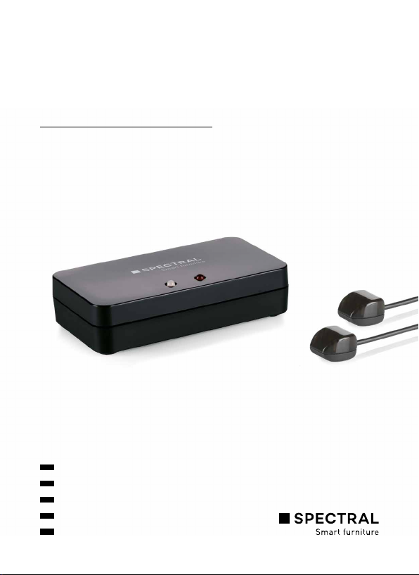
SPECTRAL SMART CONTROL
IR-LINK-SYSTEM
Quick Start Guide
DE
02
EN
06
FR
10
IT
14
NL
18
Page 2
DEUTSCH
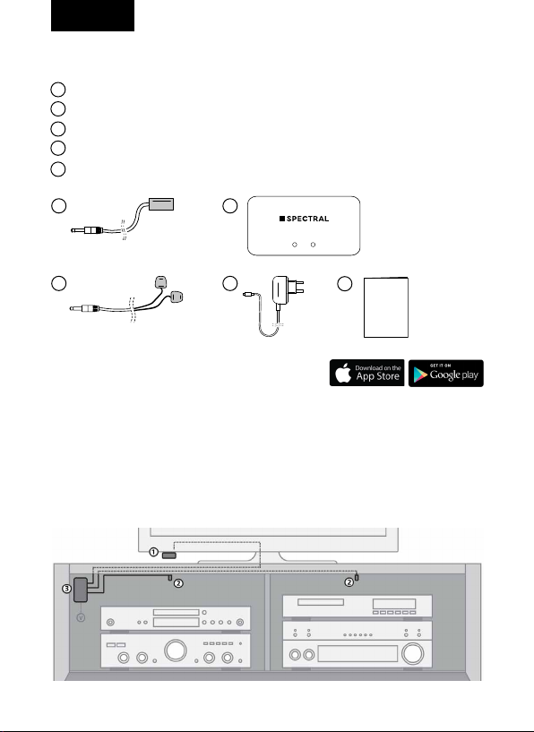
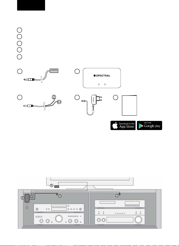
VERPACKUNGSINHALT
1
IR-Empfänger + Klebestreifen
2
3x IR-Kabel mit 2 Blaster LEDs + Klebestreifen
3
IR-Modul + Klebestreifen
4
USB-Netzteil
Quick Start Guide
5
1
2
3
4
5
Quick Start
Guide
Smart Control
IR-Link-System
Nur in Verbindung mit der Spectral
Smart Control App möglich.
1. INSTALLATION IRLINKSYSTEM
Zur Kontrolle der Betriebsfähigkeit des Systems empfehlen wir, die von Ihnen
geplante Aufstellung zunächst auszuprobieren. Schließen Sie dazu alles wie
nachstehend beschrieben an, kleben oder schrauben Sie die Komponenten
jedoch noch nicht fest.
2
Page 3
2
2
DEUTSCH
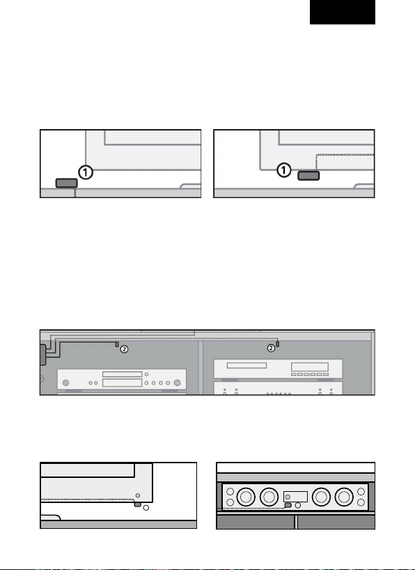
1.1 ANBRINGUNG DES IREMPFÄNGERS
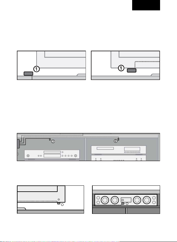
Positionieren Sie den IR-Empfänger (1) des IR-Link-Systems in Sichtweite der
(Infrarot-) Fernbedienungen Ihrer A / V-Geräte. Eine geeignete Stelle für den
IR-Empfänger wäre beispielsweise auf dem Möbelelement, in dem sich die
A / V-Geräte befinden oder in Nähe des Fernsehers.
1.2 ANBRINGUNG DER IR BLASTER LEDS
Für Geräte hinter geschlossenen Möbelklappen positionieren Sie die IR Blaster
LEDs (2) an eine beliebige Stelle im Möbelinneren, um sämtliche A / V-Geräte
in ein und demselben Fach bedienen zu können. Bei richtiger Anbringung
kann ein einziges Blaster LED sämtliche A / V-Geräte, die sich im selben Fach
befinden, bedienen.
Für Geräte im Sichtbereich (TV, Soundsystem) positionieren Sie die IR Blaster
LEDs (2) möglichst nahe am Infrarotsensor der Geräte.
3
Page 4
DEUTSCH
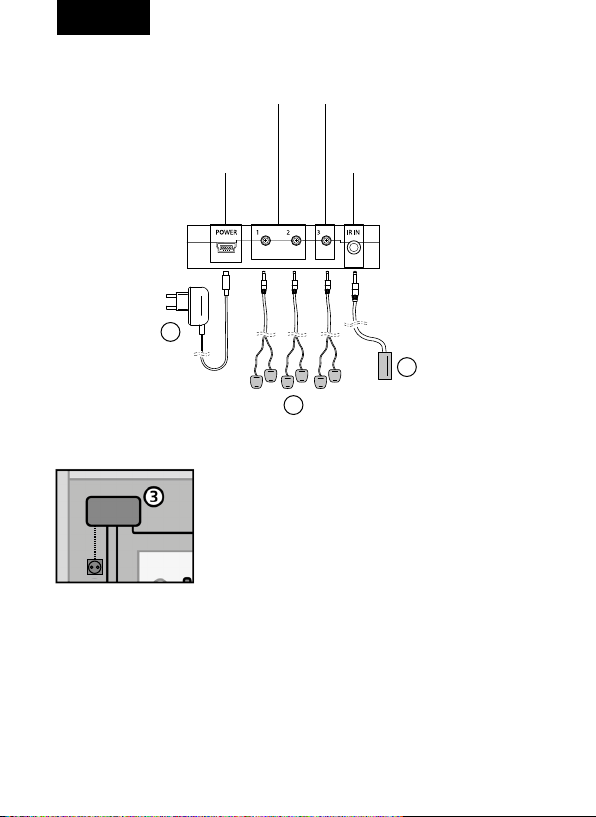
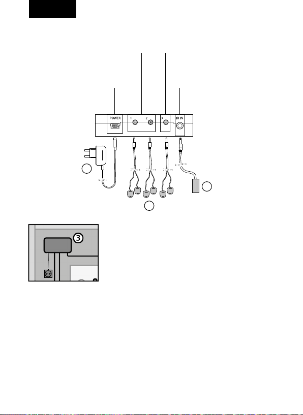
1.3 ANBRINGUNG UND ANSCHLUSS DES IR MODULS
IR OUT für Geräte hinter
geschlossenen Möbelklappen
Stromversorgung
IR OUT für Geräte im Sichtbereich (TV, Soundsystem)
IR IN für IR-Empfänger
4
1
2
Installieren Sie das IR-Modul (3) an einem erreichbaren Ort hinter oder neben Ihren A / V-Geräten und
in Reichweite einer Steckdose.
Um die Betriebsfähigkeit überwachen zu können,
müssen die Anschlüsse zugänglich und die KontrollLeuchten sichtbar bleiben.
1. Schließen Sie die IR-Kabel mit den IR Blaster LEDs (2) an die IR OUT Anschlüsse des IR-Moduls an. Verwenden Sie hierbei ausschließlich IR OUT 1
und IR OUT 2 für Geräte hinter geschlossenen Möbelklappen, IR OUT 3 (TV)
für Geräte im Sichtbereich (TV, Soundsystem), um Bedienungsprobleme zu
vermeiden.
2. Schließen Sie den IR-Empfänger (1) an den IR IN Anschluss des IR-Moduls an.
3. Schließen Sie das USB-Netzteil (4) an den POWER Anschluss des IR-Moduls
an und stecken Sie das Netzteil in eine Steckdose.
4
Page 5
DEUTSCH
1.4 FUNKTIONSPRÜFUNG
Verwenden Sie zur ersten Funktionsprüfung die IR-Fernbedienungen Ihrer
A / V-Geräte.Nach korrektem Anschluss des IR-Link-Systems blinkt die rote
Kontroll-Leuchte am IR-Modul, wenn Sie eine Taste der Fernbedienung
betätigen und diese dabei auf den IR-Empfänger richten.
Schließen Sie die Front Ihres Möbels und achten Sie darauf, dass die A / VGeräte kein unmittelbares Infrarot-Kommando von der Fernbedienung
empfangen können. Dies könnte zu Bedienungsproblemen führen.
Überprüfen Sie, ob alle A / V-Geräte auf die Signale der IR-Fernbedienungen
reagieren. Korrigieren Sie ggf. die Position des IR-Empfängers (1) und der
IR Blaster LEDs (2).
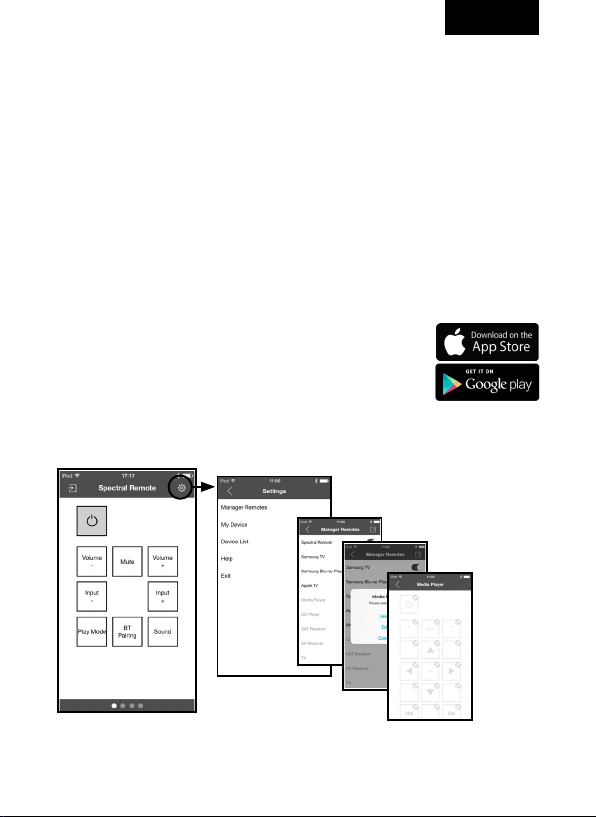
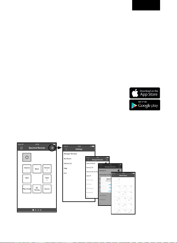
2. INSTALLATION SMART CONTROL APP
Laden Sie im App Store oder bei Google play die Spectral
Smart Control App auf Ihr iPhone, iPad oder Ihren iPod
herunter und öffnen Sie die App.
Nach der erfolgreichen Verbindung mit Ihrem Smart Control
Modul können Sie eine Auswahl an vorprogrammierten
Geräten sofort bedienen, eigene Remotes anlegen und
einzelnen Tasten individuell belegen und editieren.
Weitere Informationen und eine ausführliche Anleitung finden Sie
im Hilfemenü der App und unter app.spectral.eu
5
Page 6
ENGLISH
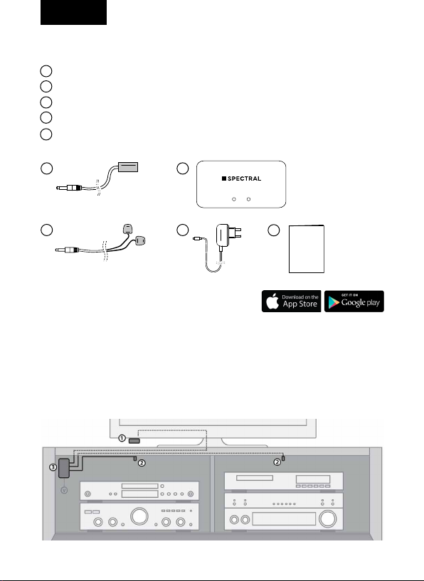
PACKAGING CONTENTS
1
IR receiver + adhesive tape
2
3x IR cable with 2 IR Blaster LEDs + adhesive tape
3
IR module + adhesive tape
4
USB power adapter
Quick Start Guide
5
1
2
3
4
5
Quick Start
Guide
Smart Control
IR-Link-System
Only available in combination with
the Spectral Smart Control App .
1. INSTALLATION IR LINK SYSTEM
To check the operability of the system, we recommend trying your planned
set-up first. To do so, connect everything as described in the following steps,
but do not adhere or screw the components on tightly.
6
Page 7
2
2
ENGLISH
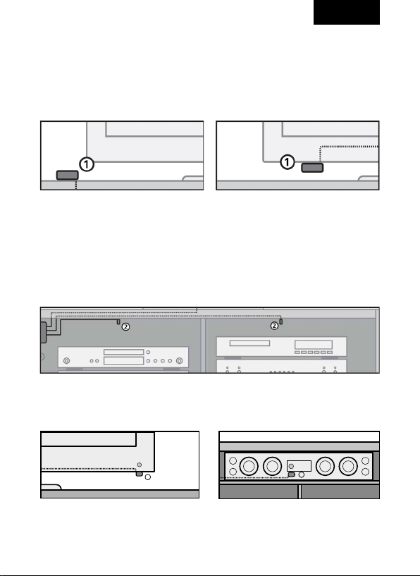
1.1 SETTING UP THE IR RECEIVER
Place the IR receiver (1) of the IR link system within the range of your audio/
video devices’ (infrared) remote control.
A suitable location for the IR receiver would be, for example, on the furniture
element in which the audio/video devices are located or near the TV.
1.2 SETTING UP THE IR BLASTER LEDS
For devices behind closed furniture flaps mount the IR Blaster LEDs (2) on
any place inside the furniture to operate all audio/video devices in one and
the same compartment. When properly mounted, a single IR LED Blaster can
operate all audio/video devices that are in the same compartment.
For devices within sight (TV, soundsystem) mount the IR Blaster LEDs (2) as
close as possible to the devices‘ IR sensor.
7
Page 8
ENGLISH
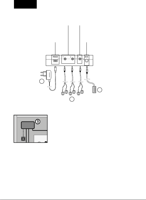
1.3 MOUNTING AND SETTING UP THE IR MODULE
IR OUT ports for devices
behind closed furniture flaps
power supply
IR OUT port for devices within
sight (TV, soundsystem)
IR IN port for IR receiver
4
1
2
Install the IR module (3) in an accessible place
behind or next to your audio/video devices and
within reach of a power outlet.
In order to monitor the operation ability, the ports
must be accessible and the indicator lights must
remain visible.
1. Conncet the IR cable with the IR Blaster LEDs (2) to the IR OUT ports of the
IR module. To avoid operation problems, use the IR OUT 1 and IR OUT 2
ports for devices behind closed furniture flaps only, the IR OUT 3 (TV) port
for devices within sight (TV, soundsystem).
2. Connect the IR receiver (1) to the IR IN port of the IR module.
3. Connect the USB power adapter (4) to the POWER supply of the IR module
and plug in the USB power adapter.
8
Page 9
ENGLISH
1.4 OPERATION TEST
For the first operation test use the IR remote contols of your audio/video
devices. Once the IR link system is properly connected, the red indicator light
will flash on the IR module, when you press a key on the (infrared) remote
control while pointing it at the IR receiver.
Close the front of your furniture and make sure that the audio/video devices
cannot receive a direct IR command from the remote control. This could lead
to operation problems.
Check if all audio/video devices respond to the signals of your IR remote
controls. If necessary, adjust the position of the IR receiver (1) and the IR
Blaster LEDs (2).
2. INSTALLATION SMART CONTROL APP
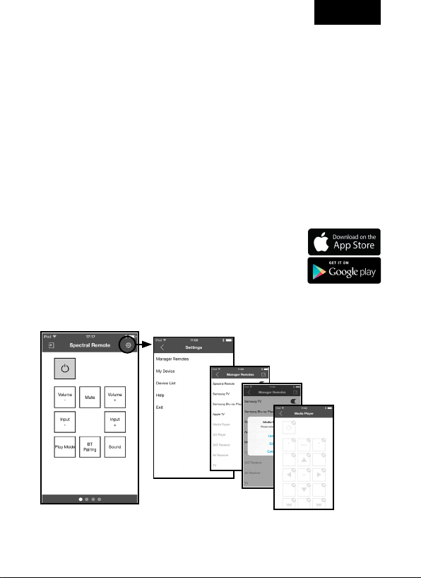
Download the Spectral Smart Control App from the App
Store or from Google Play on to your iPhone, iPad or iPod
and open the app.
Once successfully connected with your Smart Control
module, you can operate a selection of pre-programmed
devices right away, create your own remotes, and program
and edit each key individually.
For more information and detailed instructions, look at the app‘s help
menu and visit app.spectral.eu.
9
Page 10
FRANCE
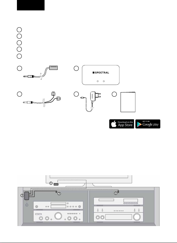
CONTENU DE L’EMBALLAGE
1
Récepteur IR + bande adhésive
2
3x câble IR avec 2 LED Blaster IR + bande adhésive
3
Module IR + bande adhésive
4
Bloc d’alimentation USB
Guide de démarrage rapide
5
1
2
3
4
5
Quick Start
Guide
Smart Control
IR-Link-System
Uniquement possible en conjonction
avec Spectral Smart Control App .
1. INSTALLATION SYSTÈME DE LIAISON IR
Pour vérifier le bon fonctionnement du système, nous vous recommandons de
tester dans un premier temps la configuration choisie. Raccordez à cet effet
tous les éléments comme décrit ci-dessous, sans toutefois coller ou visser les
composants de manière définitive.
10
Page 11
2
2
FRANCE
1.1 MISE EN PLACE DU RÉCEPTEUR IR
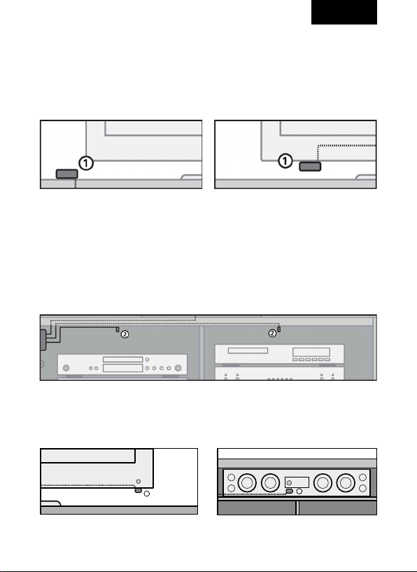
Positionnez le récepteur IR (1) du système de liaison IR à portée des télécommandes (infrarouge) de vos appareils A / V. Un endroit approprié pour installer
le récepteur IR peut être par exemple la partie extérieure du meuble qui abrite
vos appareils A / V ou encore à proximité de votre téléviseur.
1.2 MISE EN PLACE DES LED BLASTER IR
Pour les appareils situés derrière des volets de meuble fermés, positionnez
les LED Blaster IR (2) à n’importe quel endroit à l’intérieur du meuble afin
qu’elles puissent commander tous les appareils A/V dans un seul et unique
compartiment. Si le montage est correct, une seule LED Blaster suffit à commander l’ensemble des appareils A/V logés dans un même compartiment.
Pour les appareils situés dans le champ de vision (TV, système audio), positionnez les LED Blaster IR (2) aussi près que possible du capteur à infrarouge
des appareils.
11
Page 12
FRANCE
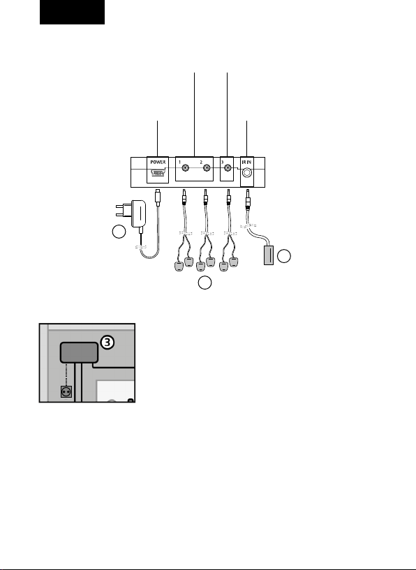
1.3 MONTAGE ET RACCORDEMENT DU MODULE IR
IR OUT pour les appareils
derrière des volets de meuble
fermés
Alimentation électrique
IR OUT pour les appareils
situés dans le champ de
vision (TV, système audio)
IR IN pour récepteur IR
4
1
2
Installez le module IR (3) à un endroit accessible,
derrière ou à côté de vos appareils A / V et à portée
d’une prise secteur.
Pour que vous puissiez surveiller le bon fonctionnement de l’ensemble, les connexions doivent
rester accessibles et les témoins lumineux doivent
demeurer visibles.
1. Raccordez les câbles IR avec les LED Blaster IR (2) aux prises IR OUT du
module IR. Pour cela, utilisez exclusivement IR OUT 1 et IR OUT 2 pour
les appareils situés derrière des volets de meuble fermés, IR OUT 3 (TV)
pour les appareils situés dans le champ de vision (TV, système audio) afin
d’éviter tout problème de commande.
2. Raccordez le récepteur IR (1) à la prise IR IN du module IR.
3. Raccordez le bloc d’alimentation USB (4) à la prise POWER du module IR
et branchez le bloc d’alimentation sur une prise secteur.
12
Page 13
FRANCE
1.4 TEST DE FONCTIONNEMENT
Pour le premier test de fonctionnement, utilisez les télécommandes infrarouge
de vos appareils A / V. Après raccordement correct du système de liaison IR, le
témoin lumineux rouge du module IR clignote lorsque vous appuyez sur une
touche de votre télécommande tout en l’orientant vers le récepteur IR.
Fermez le volet de votre meuble TV en veillant à ce que vos appareils A / V ne
puissent pas réceptionner de signal infrarouge direct depuis la télécommande,
ce qui risquerait de poser des problèmes de commande.
Assurez-vous que tous les appareils A / V réagissent aux signaux des télécommandes infrarouge. Corrigez si nécessaire la position du récepteur IR (1) des
LED Blaster IR (2).
2. INSTALLATION SMART CONTROL APP
Téléchargez l’application Spectral Smart Control
sur votre iPhone, iPad ou iPod depuis l’App Store ou
Google play, puis ouvrez l’application.
Une fois la connexion établie avec votre module Smart
Control, vous pouvez immédiatement piloter une sélection
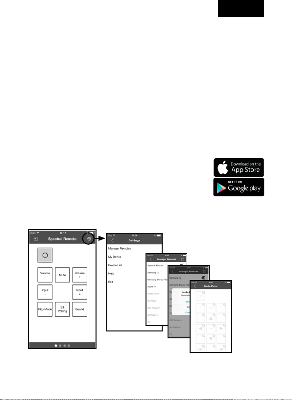
d’appareils préprogrammés, ajouter vos propres appareils
distants ou encore modifier l’affectation des différentes touches.
Pour plus d’informations et pour des instructions détaillées, consultez le
menu Aide de l’application ou le site app.spectral.eu.
13
Page 14
ITALY
CONTENUTO DELLA CONFEZIONE
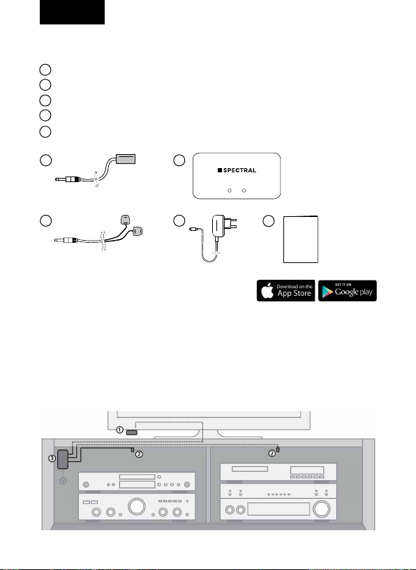
1
Ricevitore IR + striscia adesiva
2
3x cavo IR con 2 Blaster LED a infrarossi + striscia adesiva
3
Modulo IR + striscia adesiva
4
Alimentatore USB
Guida rapida
5
1
2
3
4
5
Quick Start
Guide
Smart Control
IR-Link-System
Possibile solo in combinazione
con Spectral Smart Control App.
1. INSTALLAZIONE SISTEMA DI COLLEGAMENTO IR
Per controllare la corretta funzionalità del sistema vi raccomandiamo di
provare prima la disposizione da voi selezionata. Collegare tutti gli elementi
come descritto successivamente, incollare o avvitare i componenti, ma non in
maniera definitiva.
14
Page 15
2
2
ITALY
1.1 APPLICAZIONE DEL RICEVITORE IR
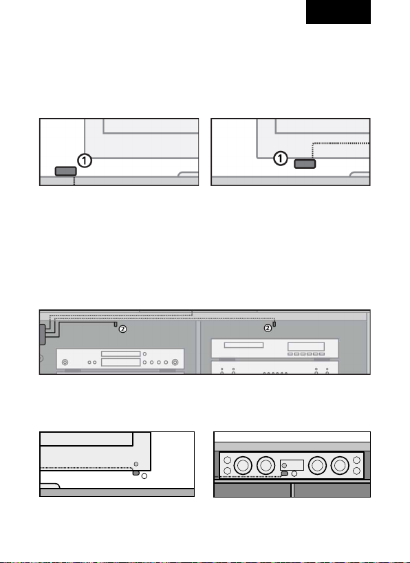
Posizionare il ricevitore IR (1) e il sistema di collegamento IR entro il raggio
visivo del vostro telecomando (ad infrarossi) dei vostri dispositivi audio / video.
La migliore ubicazione per il ricevitore IR sarebbe ad esempio sopra il mobile
sul quale si trovano i dispositivi audio / video o vicino al televisore.
1.2 APPLICAZIONE DEL BLASTER LED A INFRAROSSI
Per i dispositivi dietro gli sportelli del mobile, posizionare i Blaster LED IR (2)
su un punto desiderato all‘interno del mobile per poter utilizzare tutti i dispositivi audio / video e nello stesso scomparto. In caso di applicazione corretta, un
solo Blaster LED può gestire tutti i dispositivi audio / video che si trovano nello
stesso scomparto.
Per i dispositivi entro il raggio visivo (TV, sistema audio) posizionare i Blaster
LED IR (2) possibilmente vicino al sensore a infrarossi dei dispositivi.
15
Page 16
ITALY
1.3 APPLICAZIONE E COLLEGAMENTO DEL MODULO IR
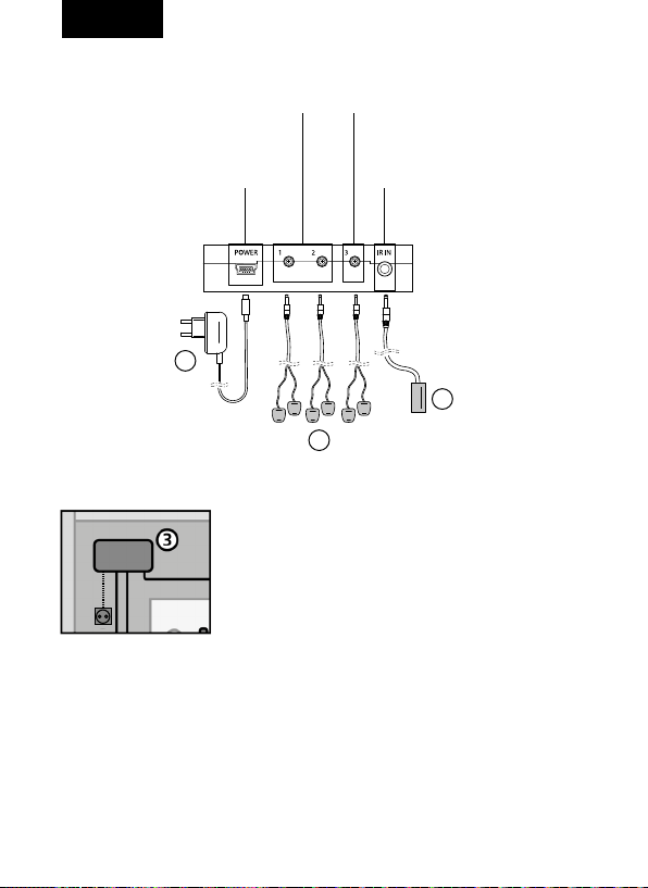
IR OUT per i dispositivi dietro
gli sportelli chiusi del mobile
Alimentazione
IR OUT per i dispositivi entro il
raggio visivo (TV, sistema audio)
IR IN per il ricevitore IR
di corrente
4
1
2
Installare il modulo IR (3) in un luogo raggiungi
dietro o accanto ai vostri dispositivi audio / video e
nel raggio d‘azione di una presa.
Per monitorare la funzionalità del sistema, i
collegamenti devono essere accessibili e le spie di
controllo devono rimanere visibili.
1. Collegare il cavo IR con i Blaster LED IR (2) nei collegamenti IR OUT del
modulo IR. Utilizzare a tale scopo esclusivamente IR OUT 1 e IR OUT 2 per i
dispositivi dietro gli sportelli chiusi del mobile, IR OUT 3 (TV) per i dispositivi
nel raggio visivo (TV, sistema audio) per evitare problemi di comando.
2. Collegare il ricevitore IR (1) al collegamento IR IN del modulo IR.
3. Collegare l‘alimentatore USB (4) al collegamento POWER del modulo IR e
inserire la spina maschio dell‘alimentatore in una presa di corrente.
16
Page 17

ITALY
1.4 CONTROLLO DELLA FUNZIONALITÀ
Utilizzare per un primo controllo della funzionalità i telecomandi IR dei vostri
dispositivi audio / video. Dopo un corretto collegamento del sistema di collegamento IR, lampeggia la luce di controllo sul modulo IR, se si preme il tasto del
telecomando e se lo si dirige verso il ricevitore IR.
Chiudere la parte frontale del mobile prestando attenzione al fatto che i
dispositivi audio / video possano ricevere sempre il comando impartito dal
telecomando in maniera diretta. Ciò potrebbe causare problemi di utilizzo.
Controllare se tutti i dispositivi audio / video reagiscono ai segnali dei telecomandi IR. Correggere eventualmente la posizione del ricevitore IR (1) e dei
Blaster LED IR (2).
2. INSTALLAZIONE SMART CONTROL APP
Scaricare nell‘App Store o nella Google play l‘App Spectral
Smart Control sul vostro iPhone, iPad o iPod e aprirla.
Dopo un collegamento avvenuto con successo col vostro
modulo Smart Control potete utilizzare da subito una
gamma di dispositivi preprogrammati, creare i propri
telecomandi, personalizzare e modificare l‘assegnazione
dei singoli tasti.
Ulteriori informazioni e una guida dettagliata si trovano nel menu aiuto
dell‘app al sito app.spectral.eu.
17
Page 18
NETHERLAND
INHOUD VAN DE VERPAKKING
1
IR-ontvanger + lijmstrook
2
3x IR-kabel met 2 IR Blaster-LEDs + lijmstrook
3
IR-module + lijmstrook
4
USB-netvoeding
Quick Start Guide
5
1
2
3
4
5
Quick Start
Guide
Smart Control
IR-Link-System
Alleen mogelijk in combinatie
met Spectral Smart Control App.
1. INSTALLATIE IRLINKSYSTEEM
Om te controleren of het systeem werkt, adviseren wij de door u ontworpen opstelling eerst te testen. Sluit daarvoor alles aan zoals hierna wordt beschreven,
lijm of schroef de componenten echter nog niet vast.
18
Page 19
NETHERLAND
2
2
1.1 AANBRENGEN VAN DE IRONTVANGER
Positioneert u de IR-ontvanger (1) van het IR-Link-Systeem in het zichtveld
van de (infrarood-) afstandsbedieningen van uw a/v randapparatuur. Een goede
positie van de IR-ontvanger is bijvoorbeeld geplaatst op het meubel of direct
onder de TV, zodat de IR-ontvanger gepositioneerd is in de buurt van de a/v
randapparatuur.
1.2 AANBRENGEN VAN DE IR BLASTERLEDS
Voor randapparatuur achter gesloten meubelkleppen positioneert u de IR
Blaster LED’s (2) op een beschikbare plek aan de voorzijde van het meubel,
waarbij u alle randapparaten geplaatst in hetzelfde vak in één keer kunt
bereiken. Het juist positioneren van één enkele IR-blaster led zorgt ervoor dat
complete randapparatuur in één meubelvak bereikt en bediend kan worden.
Voor apparatuur in het zichtveld (TV, sound-systeem) positioneert u de IR
Blaster LED’s (2) indien mo gelijk direct naast of op de IR-ontvanger sensor van
het betreffende apparaat.
19
Page 20
NETHERLAND
1.3 INSTALLATIE EN AANSLUITEN VAN DE IRMODULE
IR OUT voor apparaten achter
gesloten meubelkleppen
stroom aansluiting
IR OUT voor apparaten in het
zichtveld (TV, sound-systeem)
IR IN voor IR-ontvanger
4
1
2
Installeert u de IR-module (3) op een bereikbare plaats
achter het meubel of in de buurt van de randapparatuur, waarbij er rekening wordt gehouden met de
lengte van de stroomstekker naar het stopcontact.
Om de werking van de IR Blaster te kunnen controleren,
is het verstandig om de IR-module op een bereikbare
en zichtbare plek te plaatsen zodat de controle lampjes
te zien zijn.
1. Sluit de IR-kabel met de IR Blaster LED’s (2) aan op de IR OUT ingang van
de IR-module. Gebruik hierbij aansluiting de ingangen IR OUT 1 en IR OUT 2
voor apparatuur achter gesloten meubelkleppen, IR OUT 3 (TV)is alleen voor
apparaten in het zichtveld (TV, sound-systeem), dit om bedieningsproblemen
te vermijden.
2. Sluit u de IR-ontvangen (1) aan op de IR-IN aansluiting van de IR-module.
3. Sluit u de USB-stekker (4) aan op de POWER-aansluiting van de IR-module,
en steek de stekker in de stekkerdoos of direct in een vrije wandcontactdoos.
20
Page 21
NETHERLAND
1.4 FUNCTIONERINGSTEST
Gebruik voor de eerste functioneringstest de normale IR afstandsbedieningen
van uw a/v randapparatuur. Indien de aansluitingen op de juiste manier aansloten zijn op het IR-Link-Systeem zal het rode controle lampje van de IR-module
knipperen, zodra u een toets op de bestaande afstandsbediening indrukt. U
richt hierbij de afstandsbediening op de IR-ontvanger van het IR-Link-Systeem.
Sluit hierna de klep van het meubel en let er daarbij op dat de a/v apparatuur
geen rechtstreeks infrarood signaal meer kunnen ontvangen van de originele
afstandsbediening. Dit zou tot bedieningsproblemen kunnen leiden. Test
daarna of alle a/v randapparatuur op de signalen van de IR afstandsbedieningen
reageren. Indien noodzakelijk verplaatst u de positie van de IR-ontvanger (1) en
de IR Blaster LED’s (2).
2. INSTALLATIE SMART CONTROL APP
Download in de App Store of in Google play de Spectral
Smart Control App voor de iPhone, iPad of uw iPod en
open na installatie de App.
Na een succesvolle verbinding met de Smart Control module is het mogelijk
om te kiezen uit een lijst van voorgeprogrammeerde apparaten, welke daarbij
na het selecteren direct te bedienen zijn. Tevens is het mogelijk om een eigen
afstandsbediening te programmeren, waarbij er de mogelijkheid is om individuele afstandsbediening toetsen te selecteren en naar wens te bewerken.
Extra informatie en een uitgebreide handleiding is te vinden in het
help-menu van de App zelf of onder app.spectral.eu.
21
Page 22

TECHNISCHE DATEN
IR-Modul
Speisung POWER:
100 – 240V AC 50/60Hz, mini USB
Anschlüsse:
3 x 2,5 mm, 1 x 3,5 mm Mini-Jack
Abmessungen: 80 x 45 x 20 mm
IR-Empfänger
Frequenzbereich: 30 – 60 kHz
IR-Empfangsbereich: bis zu 10 Meter
IR-Empfangswinkel: 60 º (+30 º / -30)
Abmessung Empfangsblock:
30 x 15 x 11 mm
IR-Kabel
IR-Sendebereich: 2 Meter
Abmessung IR Blaster LED:
16 x 13 x 10 mm
TECHNICAL SPECIFICATIONS
IR module
POWER:
100 – 240V AC 50/60Hz, mini USB
Ports:
3 x 2,5 mm, 1 x 3,5 mm mini jack
Dimensions: 80 x 45 x 20 mm
IR receiver
Frequency range: 30 – 60 kHz
IR reception range: up to 10 meters
IR reception angle: 60 º (+30 º / -30)
Dimension reception block:
30 x 15 x 11 mm
IR cable
IR transmission range: 2 meters
Dimension of IR Blaster LED:
16 x 13 x 10 mm
FICHE TECHNIQUE
Module IR
Alimentation :
100 – 240V AC 50/60Hz, mini-USB
Connexions :
3 x 2,5 mm, 1 x 3,5 mm mini-jacks
Dimensions : 80 x 45 x 20 mm
Récepteur IR
Bande passante : 30 – 60 kHz
Portée de réception IR : jusqu’à 10 mètres
Angle de réception IR : 60 º (+30 º / -30)
Dimensions du bloc récepteur :
30 x 15 x 11 mm
Câble IR
Portée d’émission IR : 2 mètres
Dimensions de la LED Blaster IR :
16 x 13 x 10 mm
22
DATI TECNICI
Modulo IR
Alimentazione di CORRENTE:
100 – 240V AC 50/60Hz, mini-USB
Collegamenti:
3 x 2,5 mm, 1 x 3,5 mm Mini-Jack
Dimensioni: 80 x 45 x 20 mm
Ricevitore IR
Intervallo di frequenza: 30 – 60 kHz
Intervallo di ricezione IR: fino a 10 metri
Angolo di ricezione IR: 60 º (+30 º / -30)
Dimensioni blocco di ricezione:
30 x 15 x 11 mm
Cavo IR
Intervallo di trasmissione IR: 2 metri
Dimensioni Blaster LED a infrarossi:
16 x 13 x 10 mm
Page 23

TECHNISCHE GEGEVENS
IR-module
Voeding POWER:
100 – 240V AC 50/60Hz, mini-USB
Aansluitingen:
3 x 2,5 mm, 1 x 3,5 mm mini-jack
Afmetingen: 80 x 45 x 20 mm
IR-ontvanger
Frequentiebereik: 30 – 60 kHz
IR-ontvangstbereik: tot en met 10 meter
IR-ontvangsthoek: 60 º (+30 º / -30)
Afmetingen ontvangstblok:
30 x 15 x 11 mm
IR-kabel
IR-zendbereik: 2 Meter
Afmetingen IR Blaster-LED:
16 x 13 x 10 mm
23
Page 24
GARANTIE
Für das IR-Link-System werden 2 Jahre Garantie gewährt. Die Garantiezeit beginnt mit
dem Kauf und gilt nur für den Erstkäufer. Ausgeschlossen sind Transportschäden und
Schäden, die durch unsachgemäßen Gebrauch verursacht wurden. Der Anspruch verlängert
sich nicht durch den Austausch von Bauteilen innerhalb der Garantiezeit. Wenden Sie sich
im Schadensfall bitte an Ihren Spectral Fachhändler.
WARRANTY
Spectral provides a 2 year warranty against factory defects for the IR link system.
The warranty period starts with the purchase and applies only to the first purchaser.
Transport damage and damage caused by improper use are excluded from the warranty.
Warranty cannot be extended by exchanging components during the guarantee period.
In the case of a claim, please contact your Spectral dealer.
GARANTIE
Spectral offre une garantie de 2 ans contre les défauts de fabrication pour le système de
liaison infrarouge. La période de garantie commence avec l‘achat et s‘applique uniquement
au premier acheteur. Les dommages de transport et les dommages causés par une
mauvaise utilisation sont exclus de la garantie. Garantie ne peut être prorogé par l‘échange
de composants lors de la période de garantie. Dans le cas d‘une réclamation, s‘il vous plaît
contactez votre revendeur spectrale.
GARANZIA
Spettrale fornisce una garanzia di 2 anni contro i difetti di fabbrica per il sistema di
collegamento a infrarossi. Il periodo di garanzia ha inizio con l‘acquisto e si applica solo al
primo acquirente. Danni di trasporto e danni causati da un uso improprio non sono coperti
dalla garanzia. La garanzia non può essere estesa con sostituzione di componenti durante il
periodo di garanzia. In caso di reclamo, si prega di contattare il rivenditore Spectral.
GARANTIE
Spectrale biedt een garantie van 2 jaar tegen fabricagefouten voor de IR-koppeling systeem.
De garantieperiode begint met de aankoop en geldt alleen voor de eerste koper. Transportschade en schade veroorzaakt door oneigenlijk gebruik zijn uitgesloten van de garantie.
Garantie is niet verlengd door het uitwisselen van onderdelen tijdens de garantieperiode.
In het geval van een claim, neem dan contact op met uw Spectrale dealer.
SPECTRAL AUDIO MÖBEL GMBH
Robert-Bosch-Str. 1–5 | 74385 Pleidelsheim | Germany
Fon +49 7144 88418-80 | Fax +49 7144 88418-40
[email protected] | spectral.eu
 Loading...