

Page 1

User Manual
Rackmount Systems
Models: RM5100, RM7100,
RM7200, RM7400
Page 2

Page 3

Rackmount Systems
Important
Please keep the packing materials and shipping carton.
This carton has been specially designed to protect the computer during shipping, including
shipping for upgrades or repairs to Spectral Computers (we also recommend that you insure
the contents). Please contact Spectral Computers for a return authorization number to ensure
proper handling and tracking of your computer.
Important Safety Instructions
The following instructions refer to risks of electrical shock, re or bodily injury. Please read all the
instructions carefully.
1. Read all instructions marked on the product and in the documentation before operating your
Spectral Computer.
2. Retain all safety and operating instructions.
3. Never use this product near water or a heat source.
4. Only set up the computer on a stable work surface.
5. Only operate the computer using the power source type indicated on the rating label.
6. If the computer has a voltage selector switch located on the back of the chassis, ensure that
the switch is set to the proper voltage setting for your area.
7. Do not block or cover fan grill or air vents.
8. Never insert objects of any kind into the ventilation openings.
9. Make sure the computer is properly grounded when in use. Do not attempt to plug the
computer into an outlet that is not properly grounded.
10. If an extension cord is used with your computer, ensure that the total ampere rating on the
computer does not exceed the maximum rating on the extension cord.
11. Do not step or place any objects on the power cord.
12. Do not spill anything on or into the computer.
13. To avoid electrical shock, always unplug all power, modem, and any other cables from the wall
outlets before handling the computer.
RM5100, RM7100, RM7200, RM7400
Page 4

Table of Contents
User Manual
Table of Contents
Spectral Diagrams
Front Panel Diagrams . . . . . . . . . . . . . . . . . . . . . . . . . . . . . .2
Rear Panel Diagrams . . . . . . . . . . . . . . . . . . . . . . . . . . . . . . .3
Setting Up Your System
Keyboard & Mouse . . . . . . . . . . . . . . . . . . . . . . . . . . . . . . . .4
Monitors . . . . . . . . . . . . . . . . . . . . . . . . . . . . . . . . . . . . . . . .5-7
Analog . . . . . . . . . . . . . . . . . . . . . . . . . . . . . . . . . . . . . . .5
Digital . . . . . . . . . . . . . . . . . . . . . . . . . . . . . . . . . . . . . . .6
Dual . . . . . . . . . . . . . . . . . . . . . . . . . . . . . . . . . . . . . . . . .6-7
Quad . . . . . . . . . . . . . . . . . . . . . . . . . . . . . . . . . . . . . . . .7
Thermal Controller . . . . . . . . . . . . . . . . . . . . . . . . . . . . . . .8
USB/FireWire Device . . . . . . . . . . . . . . . . . . . . . . . . . . . . . .9
Removable Hard Drive . . . . . . . . . . . . . . . . . . . . . . . . . . . . .9
Upgrading the RAM . . . . . . . . . . . . . . . . . . . . . . . . . . . . . . .10
Upgrading to 64-bit Processing . . . . . . . . . . . . . . . . . . . . . .10
Backing Up Your Files
Digital Backup System . . . . . . . . . . . . . . . . . . . . . . . . . . . . . .11-17
Features . . . . . . . . . . . . . . . . . . . . . . . . . . . . . . . . . . . . . . . . .12
System Manager in Windows . . . . . . . . . . . . . . . . . . . . . . . .12-14
Quick Start . . . . . . . . . . . . . . . . . . . . . . . . . . . . . . . . . . .12
Quick Backup . . . . . . . . . . . . . . . . . . . . . . . . . . . . . . . . .13
Complete Backup . . . . . . . . . . . . . . . . . . . . . . . . . . . . . .13
Restoring Your Computer . . . . . . . . . . . . . . . . . . . . . . . .14
System Manager in Real Mode . . . . . . . . . . . . . . . . . . . . . . .14-17
Activating the Digital Backup System Manager . . . . . . . .14
Navigating the Digital Backup System Manager . . . . . . .15-17
Registering Your PC
Registration Instructions . . . . . . . . . . . . . . . . . . . . . . . . . . .18
Warranty
Warranty Information . . . . . . . . . . . . . . . . . . . . . . . . . . . . . .19
Support
Technical Support . . . . . . . . . . . . . . . . . . . . . . . . . . . . . . . . .20
1
www.spectralcomputers.com
Page 5
Rackmount Systems
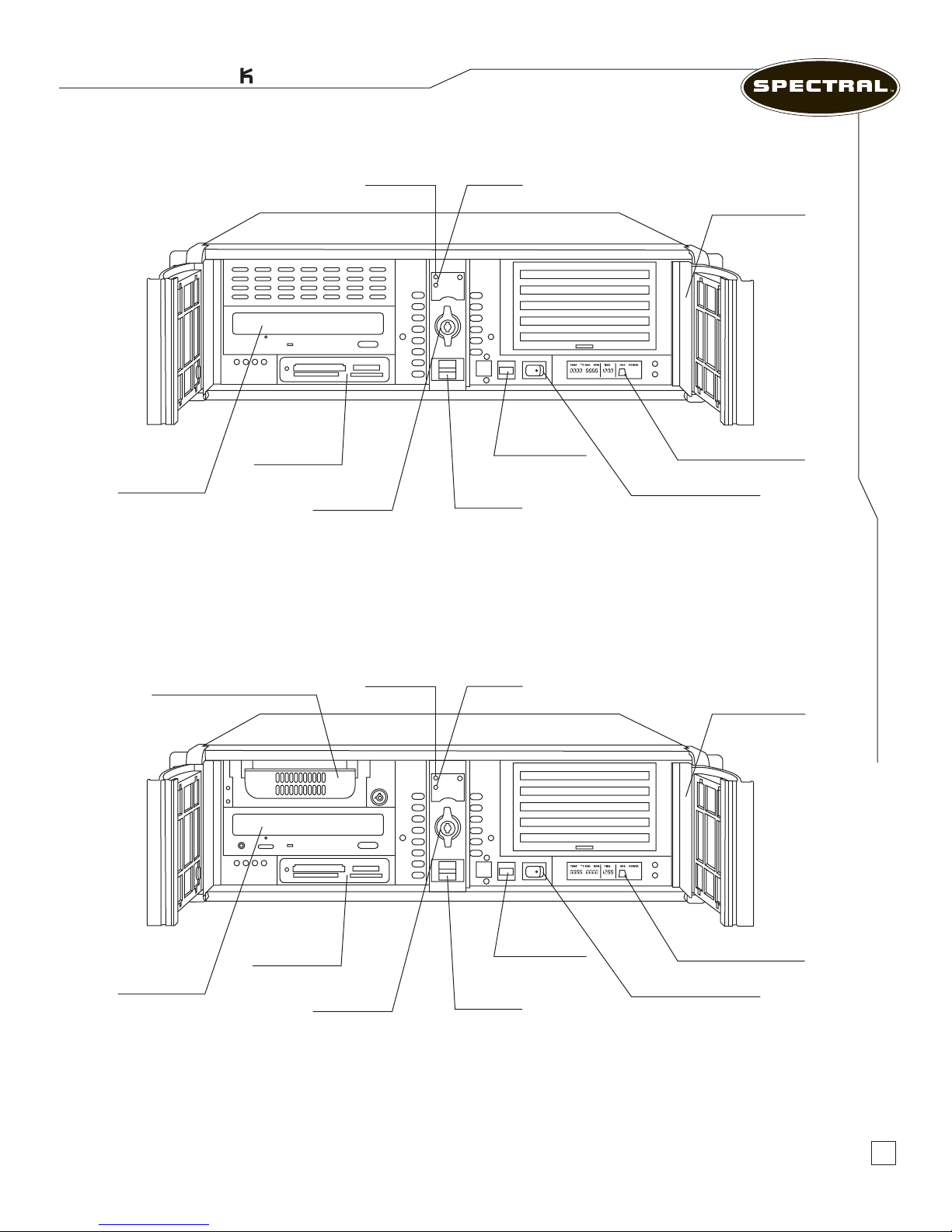
Power LED HD LED
DVD/CD/RW
Drive
Multi-Media
Card Drive
Door Lock
Figure 1.0 Front View Spectral RM5100 and RM7100
Reset Button
USB Ports
Serial Number
Front Panel Diagrams
Thermal Controller
Front Power Switch
Removable Backup Drive
DVD/CD/RW
Drive
Multi-Media
Card Drive
Door Lock
Figure 1.1 Front View Spectral RM7200 and RM7400
Power LED HD LED
Reset Button
USB Ports
Serial Number
Thermal Controller
Front Power Switch
The Musician’s PC
TM
2
Page 6
User Manual
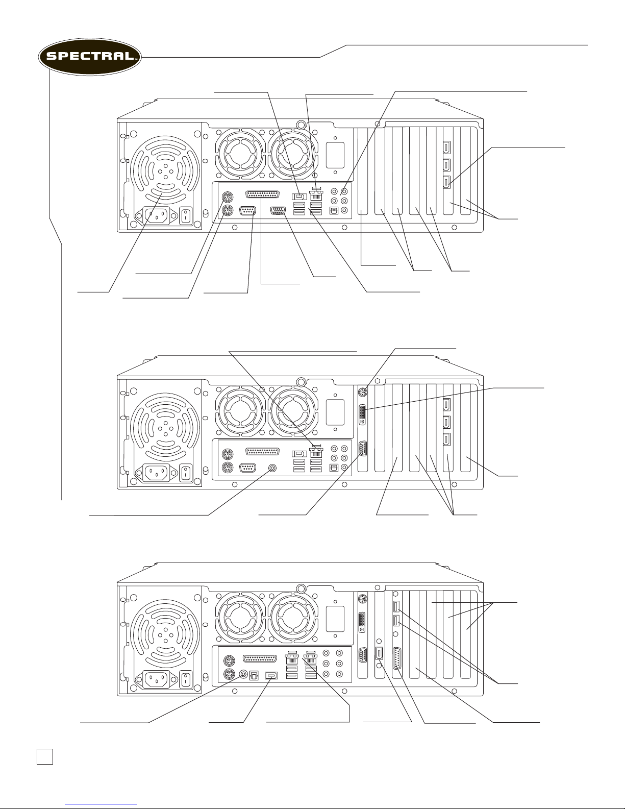
Power
Supply
Mouse (PS2)
Keyboard (PS2)
Disabled
FireWire Port
Serial
Port
(COM1)
Parallel
Port
(LPT)
LAN Port
(Ethernet 10/100)
Figure 1.2 Back View Spectral RM5100
LAN Port (Ethernet 10/100/1000)
VGA
Out
Audio Inputs & Outputs (Optional)
PCI
Express
16X
USB 2.0 Ports
S- Video Output
PCI
FireWire 400 Ports
PCI
PCI
Express
1X
Rear Panel Diagrams
Digital Audio Output (Optional)
VGA Output
PCI Express
16X
PCI
Figure 1.3 Back View Spectral RM7100, RM7200, RM7400 with Intel Processors
DVI Output
PCI
Express
1X
PCI
USB
Ports
Digital Audio Output
(Optional)
Figure 1.4 Back View Spectral RM7100, RM7200, RM7400 with AMD Processors
3
FireWire
400 Port
LAN Ports (2 ports
on the RM7400 only)
FireWire
400 Port
PCI Express
Game Port
16X
www.spectralcomputers.com
Page 7
Rackmount Systems
Setting Up Your System
CAUTION: Do not place the computer near or above a radiator or heating vent.
Keep cabinet or rack well ventilated and do not place in any area exposed to rain or
water. Be careful not to spill liquid of any kind on or into the computer.
When You First Open the Box
Before setting up your computer or components, please inspect all items for any damage that
may have accidentally occurred during shipment. Please report any issues to the dealer or contact
customer service at (818) 981-3101.
Where to Place Your Computer
Your computer is designed to be rack mounted in a location that will allow adequate cooling and
ventilation. Make sure ventilation openings are never obstructed to ensure reliable operation and
to protect the computer from overheating. Avoid exposing your computer to dirt, water, and
excessive dust.
Setting Up Your System
Keyboard & Mouse
Keyboard & Mouse
Connecting Your Keyboard
1. Locate the purple PS/2 port on the back of the chassis.
2. Properly orient the keyboard’s PS/2 connector with this port and gently push until the
connector is fully inserted. Do not force the connector into the port.
If you have a USB keyboard, insert the USB connector into any available USB port at the back or
front of the chassis.
Connecting Your Mouse
1. Locate the green PS/2 port on the back of the chassis.
2. Properly orient the keyboard’s PS/2 connector with this port and gently push until the
connector is fully inserted. Do not force the connector into the port.
PS/2 Ports have designated colors for easy identication.
The Musician’s PC
TM
4
Page 8
Monitors
User Manual
Monitors
Check to be sure that you have received a power cord and a signal cable with your monitor.
Reminder: Some monitors may require a DVI Adapter. Check your monitor’s owner’s manual.
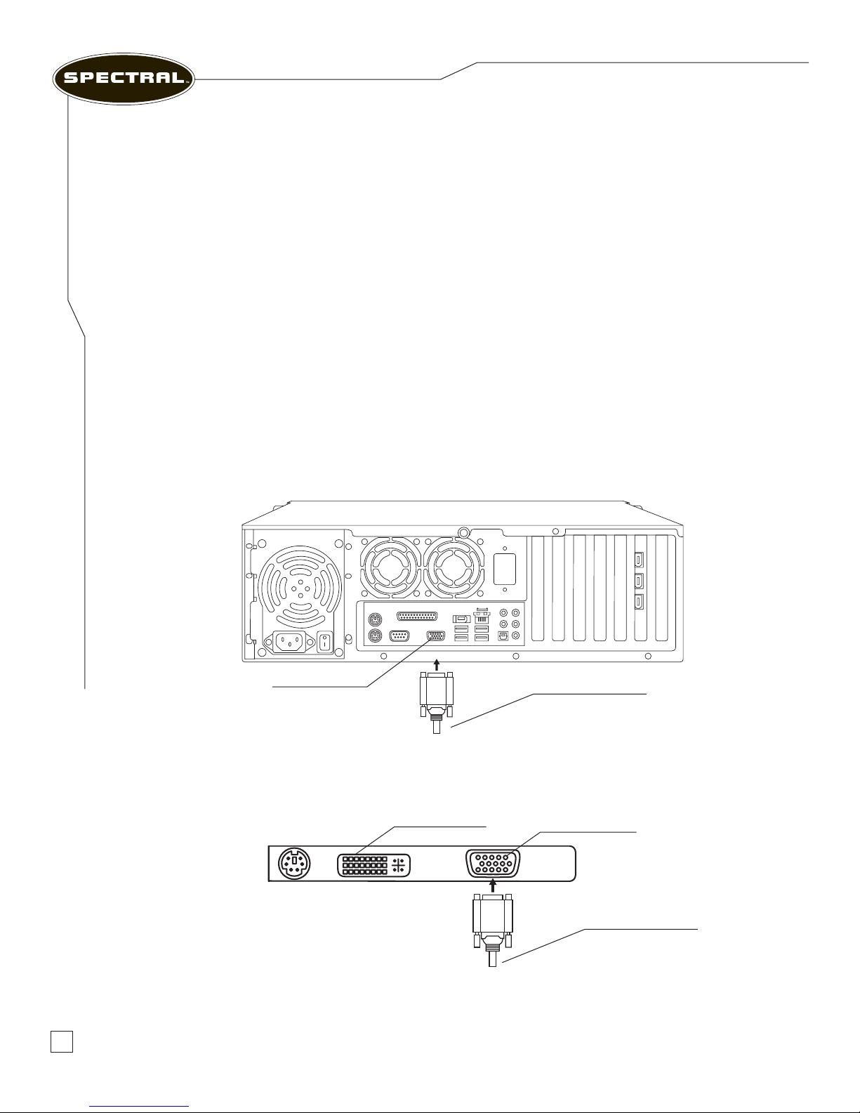
Connecting an Analog Monitor
1. Turn off your computer.
2. Connect one end of the monitor’s signal cable to the video card’s 15-pin D-Sub VGA
connector, located on the back of the chassis.
3. Connect the other end of the signal cable to the monitor’s 15-pin D-Sub VGA connector
located at the back of the monitor.
4. Secure the connections by tightening the two fasteners at each end of the signal cable.
5. Connect one end of the power cord to the monitor’s power connector located at the
back of the monitor.
6. Connect the other end of the power cord to a grounded three-prong power strip or
wall outlet.
7. Turn on your computer.
Setting Up Your System
VGA Connector
Figure 2.0 – Connecting RM5100 to a Single Analog Monitor
DVI Connector
VGA from Monitor
VGA Connector
VGA from Monitor
5
Figure 2.1 – Connecting to a Single Analog Monitor
www.spectralcomputers.com
Page 9
Rackmount Systems
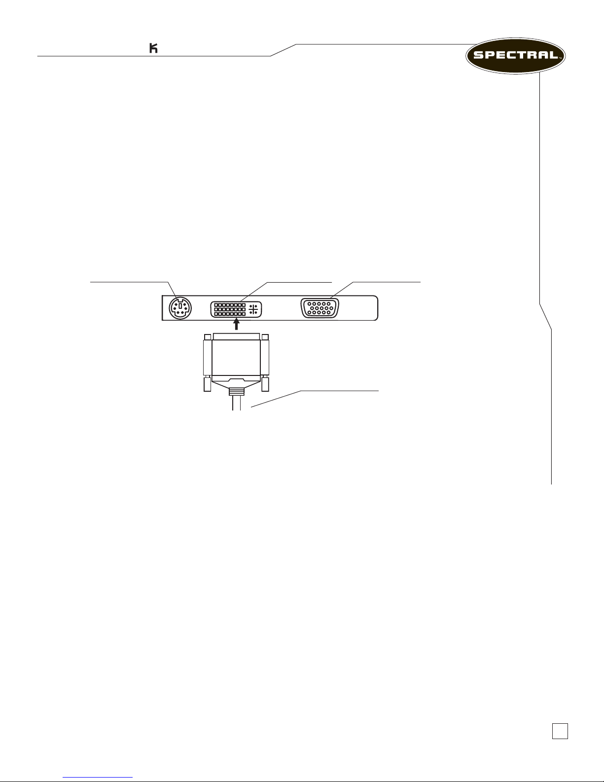
Connecting a Digital Monitor
1. Turn off your computer.
2. Connect one end of the monitor’s signal cable to the video card’s DVI connector located on
the back of your chassis.
3. Connect the other end of the signal cable to the monitor’s DVI connector located at the back
of the monitor.
4. Secure the connections by tightening the two fasteners at each end of the signal cable.
5. Connect one end of the power cord to the monitor’s power connector located at the back of
the monitor.
6. Connect the other end of the power cord to a grounded three-prong power strip or wall outlet.
7. Turn on your computer.
VGA ConnectorS-Video Connector DVI Connector
Setting Up Your System
Monitors
DVI from Monitor
Figure 2.2 – Connecting to a Single Digital Monitor
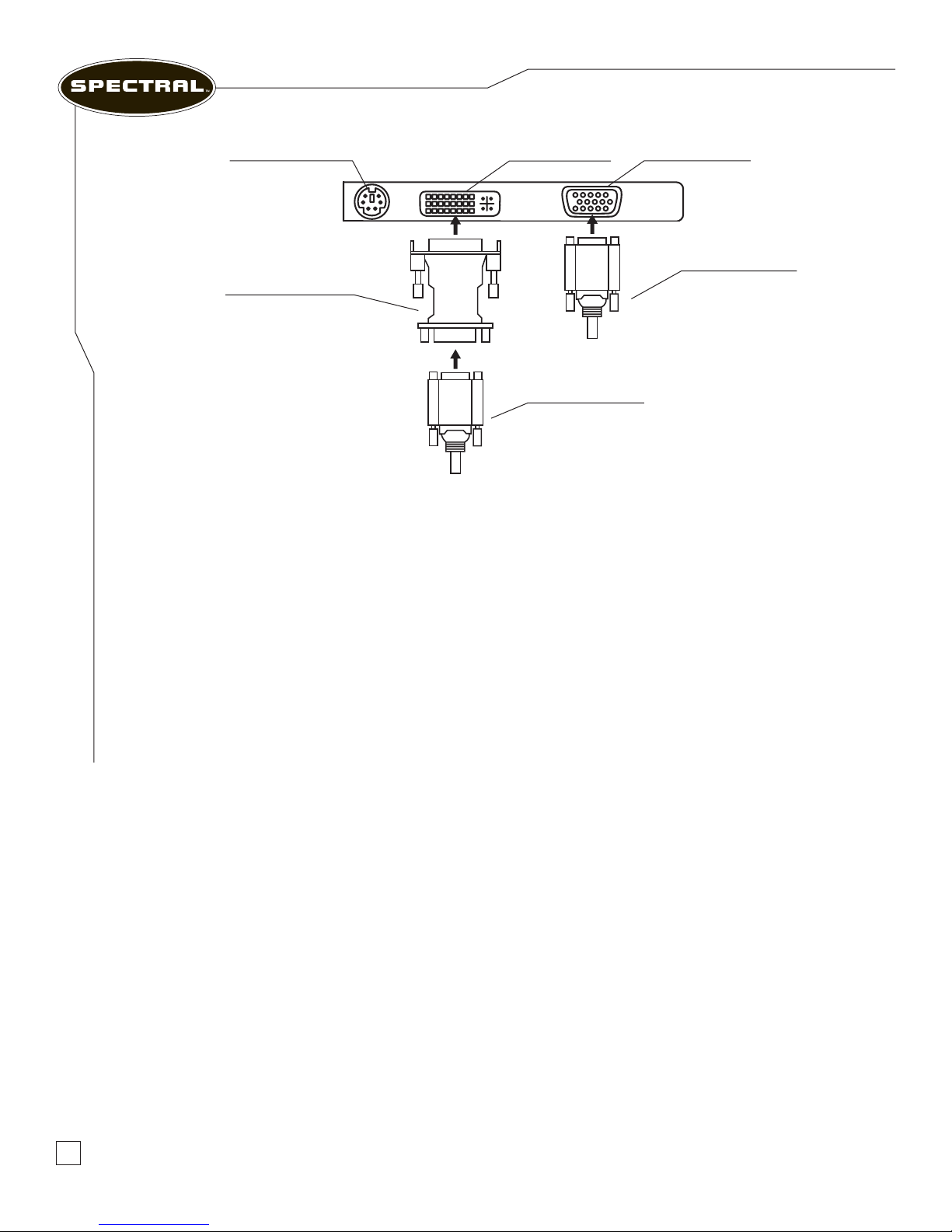
Connecting Dual Monitors
You can connect multiple monitors to your computer since your video card features
multi-monitor support (RM7100, RM7200, and the RM7400 only).
1. Turn off your computer.
2. Connect the DVI-to-VGA adapter or DVI cable to your video card’s DVI connector located
on the back of the chassis.
3. Connect one end of the rst monitor’s signal cable to the DVI-to-VGA adapter.
4. Connect other end to the 15-pin D-Sub VGA connector at the back of the monitor.
5. Connect the second monitor’s signal cable to the video card’s 15-pin D-Sub VGA connector.
6. Connect other end to the 15-pin D-Sub VGA connector at the back of the monitor.
7. Secure the connections by tightening the fasteners at each end of the signal cables
(not too tight).
8. Connect the power cord to the 3-prong connector located at the back of the monitor.
9. Plug the power cord to a grounded power strip, uninterruptible power supply, or wall outlet.
10. Repeat steps 8 and 9 for the second monitor. Then turn on your computer.
The Musician’s PC
TM
(Continued on page 7)
6
Page 10
User Manual
VGA ConnectorS-Video Connector DVI Connector
Monitors
Setting Up Your System
VGA to DVI Monitor
(if needed)
VGA from Monitor
Figure 2.3 – Connecting to Dual Monitors
VGA from Monitor
11. Left-click your Start Menu. Scroll over Settings and left-click the Control Panel.
12. When the Control Panel opens, double-click the Display Properties icon.
13. When the Display Properties dialog box appears, click the Settings tab.
14. On the Settings tab, change the Display pull-down menu to the second monitor.
15. Now, check the box marked “Extend my Windows desktop onto this monitor.”
16. Hit the Apply button when you’ve nished making the changes.
Note: The S-Video Connector can also be used as the second monitor video output.
7
Connecting Quad Monitors
The RM7100 and higher can accommodate a second PCI Express video card, allowing
unprecedented graphics speed with four monitors.
www.spectralcomputers.com
Page 11
Rackmount Systems
Thermal Controller
CAUTION: Do not attempt to install or repair the Thermal Controller unless you are a
trained computer technician. It is easy to break delicate components in the process, which
could void your warranty.
Setting Up Your System
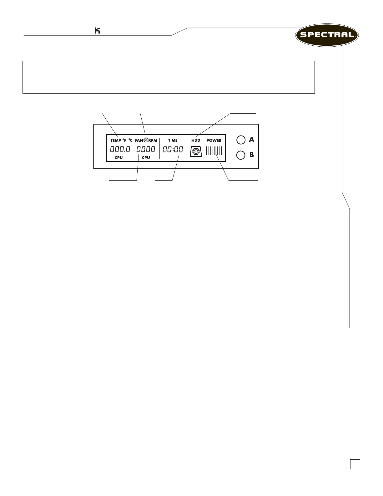
Temperature CPU/SYS-r/SYS-f Fan Status
Fan Speed Clock Power Icon
Figure 2.4 – Thermal Controller
HDD Icon
Features
•Monitoring temperature of CPU, and System’s Rear and Front (SYS-r / SYS-f)
•Speed detection and control of 3 fans
•The alarm sounds in the event of a fan malfunction or overheating
How to setup
1. On the front bezel you can nd buttons A and B for setup.
2. Temperature Limits Setup: Press A for 3 seconds to set up maximum temperature
limit. Adjust the alarm temperature with button A and B when numbers are ashing.
The next setup setting will continue in 5 seconds. The factory default overheating settings
are set as CPU= 65 ºC, SYS-r (rear) = 55 ºC, SYS-f (front) = 50 ºC.
Thermal Controller
3. Time Setup: Press button B for 3 seconds to adjust the time (minute and hour).
Use button A and B to select minutes when the number is ashing. Wait 3 seconds
for hour setup. Setup mode will terminate if left untouched over 3 seconds.
4. Temperature Type Selection: Press both button A and B to select ºF or ºC.
5. Alarm: An audible alarm will beep for 20 seconds in an overheat condition or if any
fan speed is lower than 600rpm. Fan RPM and Temperature digits will keep ashing until
the problem is solved.
The Musician’s PC
TM
8
Page 12
USB/FireWire Device
User Manual
Connecting a USB or FireWire Device
Plug the USB or FireWire device into its respective port on your computer. Windows XP
will detect the device and attempt to install the appropriate driver automatically. In some cases,
Windows may require a driver. This driver is located on the software CD that is included with
the device. Otherwise, Windows will automatically install the device with the driver in its
database. We suggest updating the driver at a later date for maximum performance. For further
information, please refer to your device’s operating manual. For the RM5100 and RM7100, only
use the three FireWire ports located on the PCI card.
Your Multi-Media Card Reader
The card reader has four slots for various types of media cards.
•CF Compact Flash •SD Secure Digital
•Microdrive •MMC Multi-Media Card
•SM Smart Media • Memory Stick
Setting Up Your System
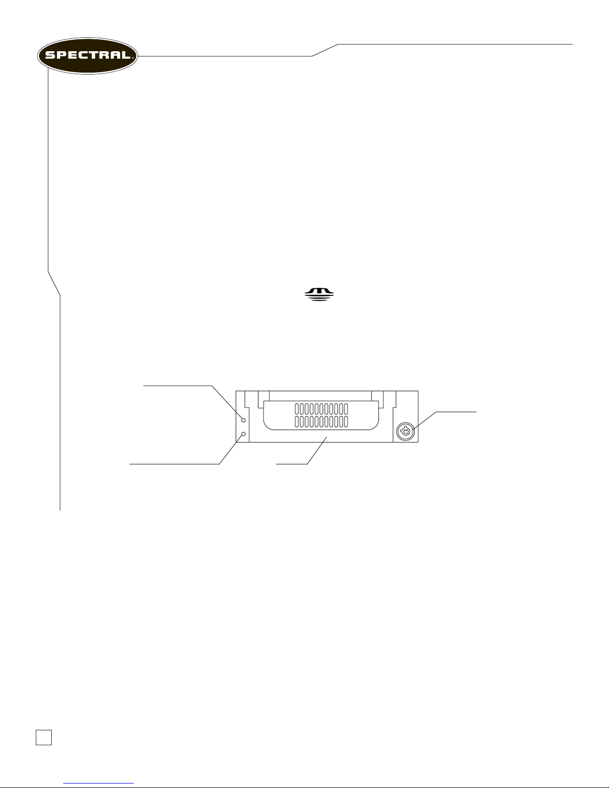
Your Removable Backup Hard Drive (RM7200 and RM7400 Only)
Power Indicator
Key Lock
HDD Access Indicator Handle
Figure 2.5 – Removable Hard Drive
Removing the Rack from the Carrier Body
Make sure that the computer is not accessing the Removable Hard Drive. Insert the miniature
key provided into the keyhole and turn the key clockwise to shut down and unlock the hard drive.
Wait 20 to 30 seconds for the hard drive to spin down. Lift up the handle and pull outward to
remove the carrier from the receiving frame.
Inserting a Carrier into the Receiving Frame
Insert the carrier in the receiving frame and push it in all the way as far as it will go. Fold down the
handle and turn the key counter-clockwise to lock the drive and start it up. Wait 20 to 30 seconds
for the hard drive to spin up before accessing it from the computer.
9
www.spectralcomputers.com
Page 13
Rackmount Systems
Upgrading the RAM
Please contact Spectral Computers if you want to upgrade the RAM of your computer.
All RAM chips must be matched and certied by Spectral Computers to function properly.
Use of a different brand or unmatched memory chips may result in system malfunction.
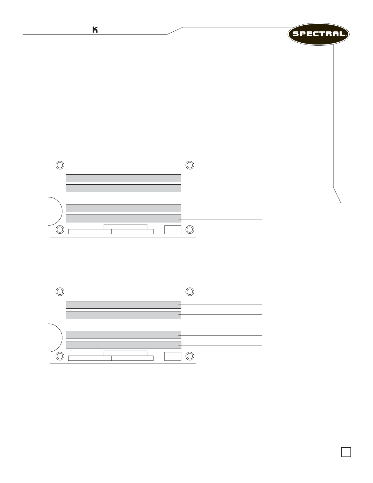
Spectral Computers use dual channel memory. There are four DIMM sockets, two for Channel A
and two for Channel B. The conguration of the DIMMs in Channel B sockets should always be
identical to the conguration in Channel A sockets.
Using Two DIMMS
The DIMM 0 (blue) sockets of both channels are populated with identical DIMMs.
Setting Up Your System
1 GB
1 GB
Channel A, DIMM 0
Channel A, DIMM 1
Channel B, DIMM 0
Channel B, DIMM 1
Using Four DIMMs
The combined capacity of the two DIMMs in Channel A equals the combined capacity of the two
DIMMs in Channel B. Also, the DIMMs are matched between DIMM 0 and DIMM 1 of both channels.
256MB
512MB
256MB
512MB
Channel A, DIMM 0
Channel A, DIMM 1
Channel B, DIMM 0
Channel B, DIMM 1
Upgrading the RAM
Upgrading to 64-bit Processing
Your new Spectral computer supports 64-bit EMT that can only be utilized by using an operating
system that supports 64-bit, such as Windows XP x64 Edition. Also, to take full advantage of the
64-bit execution platform, your application must be written to support 64-bit processing. In addition,
any additional hardware being used, such as audio cards, needs to have x64 drivers. Please contact
Spectral Computers if you want to upgrade the OS of your computer to x64.
The Musician’s PC
TM
10
Page 14

User Manual
Bac ing Up Your Files
Backing up protects you from losing important data if the hard drive fails or you accidentally
delete les. Your Spectral computer contains two or more hard drives:
• The system drive for the Operating System, system les, programs and settings as well
as other documents
• The recording drive (or RAID drives in the RM7200 and RM7400) for Audio data
• The removable hard drive (RM7200 and RM7400 only)
You can backup les from the hard drives to CD-R or DVD-R discs using the onboard optical
drive, or to an external USB2 or FireWire drive. On the RM7200 and RM7400, you can also use
the removable hard drive for backup and transfers.
You should back up your les regularly and important les should be kept at least in two
different places.
For the system drive, we recommend using a software package that can make a full image of
your hard drive. The image recovery software will recover the operating system and settings
to the state prior to the backup.
The Digital Backup System
CAUTION: The Digital Backup System does not substitute the need to backup on external
devices such as DVD/CD media or removable/external hard drives. Its main role is to protect the
operating system and installed programs on drive C: and it does not back up any data residing
on other hard drives such as the recording hard drive. Also it does not protect the user from
loss of data due to a system hard drive failure, since the backup data resides on the system
drive in a hidden partition.
Digital Backup System is an innovative real-time system restoration utility. Once installed, the
Digital Backup System continually monitors and keeps a complete record of all activities on the
system hard drive. The Digital Backup System gives you the power to recover lost data after a
system crash, virus attack, faulty software installation, accidental le deletion or unintentional
formatting of the hard disk. In merely a few minutes, if not seconds, all of the contents of your
hard disk can be restored back to a point in time when your computer was functioning properly.
The Digital Backup System is different from general-purpose backup software, using a unique
real-time incremental backup technology, that takes only 5 to 10 percent of the hard disk space.
It can be set to automatically back up the system once every hour or day, or at each system start-up.
11
www.spectralcomputers.com
Page 15
Rackmount Systems
Features
100% Protection: Allows you to instantly recover from accidental disk formatting, le deletion,
virus attacks or system crash. The Digital Backup System offers complete system protection,
24 hours a day, 365 days a year.
Kills Viruses, Rescues Files: Infected or damaged les can be rescued in seconds by
reversing the hard drive to a previous backup point.
Only a Fraction of Disk Space Used: Digital Backup System uses a unique real-time
incremental backup technology, taking up only 5 to 10 percent of the hard disk space.
Password Protection: Using the Digital Backup System, you can lock your system at the DOS
level. No unauthorized person can use your computer.
Personalize and Secure Complete Backup: Name a Backup Point and lock it to prevent
accidental removal.
Complete Backup Points: Stores a permanent copy of your hard disk, so even after years, you
can restore your system back to the day you rst installed the Digital Backup System.
Easy to Use: Now you can easily restore a computer back to working order without having to
call technical support.
Intelligent Data Integrity Checking: Checks the data integrity of the latest Incremental
Backup Point and marks it as “untrusted” if any inconsistencies are found.
Virtually Unlimited Backup Points: The Digital Backup System can set up unlimited
Incremental Backup Points, limited only by the hard disk space available.
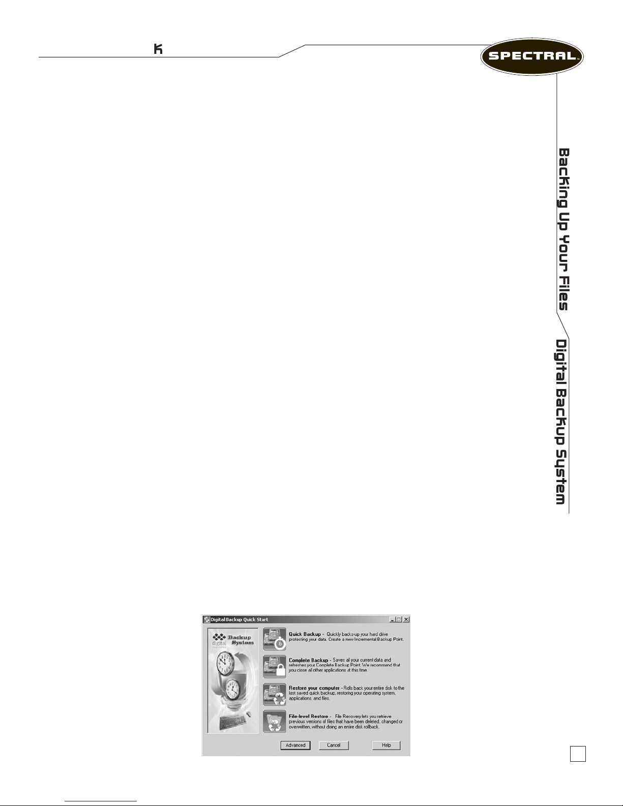
The Digital Backup System Manager in Windows
Quick Start
Select Start on the Windows taskbar, then Programs › Digital Backup System › Digital Backup
System or double-click the Digital Backup System icon on the desktop to launch the Digital
Backup System Quick Start guide.
The Musician’s PC
TM
12
Page 16
User Manual
Quick Backup
The Quick Backup option is used for quickly creating a new Incremental Backup point to
backup your hard drive and protect your data.
Click the Quick Backup button. The Digital Backup System will lock the hard drive. If any program
is currently writing to the hard disk, the Digital Backup System will stop creating the Backup Point.
If your computer locks up during this period, restart it manually and try again.
Note: The Digital Backup System does not create new Backup Points if it is unable to lock your hard drive.
Close ALL applications when you create a new Backup Point.
Select Close when you have successfully created a new Backup Point. In this step you will not need
to restart your PC.
It is strongly recommended you create a Quick backup point prior to installing any new software
or hardware. By doing so, you could reverse in seconds any problems arising from the installation.
It is also highly recommended you reboot the computer prior to creating a backup point.
Complete Backup
The Complete Backup option allows users to save all data on the hard disk as a Complete
Backup Point. This feature will overwrite the factory backup with your own backup if there
is enough space.
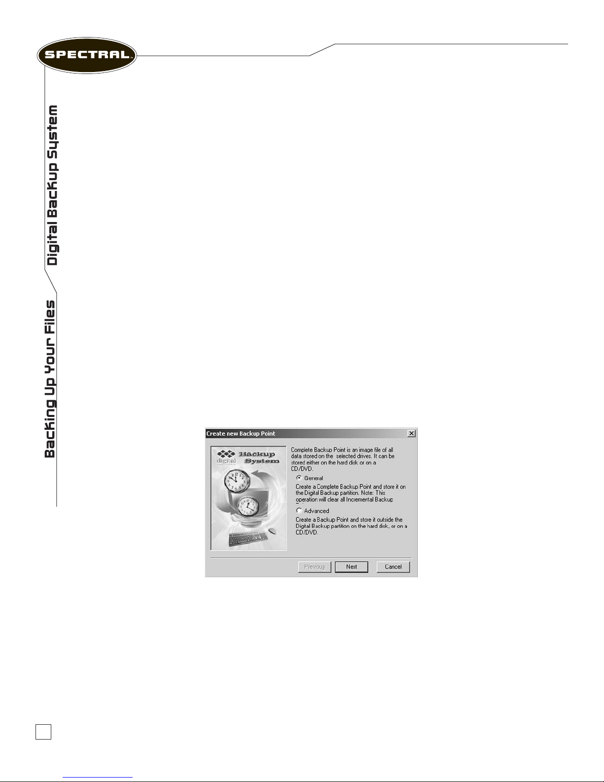
Click the Complete Backup button to open the dialog box shown below.
There are two different kinds of Complete Backup Points: General Complete Backup Point and
Advanced Complete Backup Point.
The General Backup Point can back up the rst hard disk that is protected by the Digital Backup
System only. It is located in the Digital Backup System partition and only one General Backup
Point is allowed to be created.
The Advanced Complete Backup Point is not supported on this version. Always select General.
13
www.spectralcomputers.com
Page 17
Rackmount Systems
Restoring Your Computer
CAUTION: When recovering from a backup point, all changes made to the system drive
since the backup point will be erased when recovering. We strongly recommend moving new
data created on the system drive after the backup point to a different hard drive or to a DVD
prior to recovering.
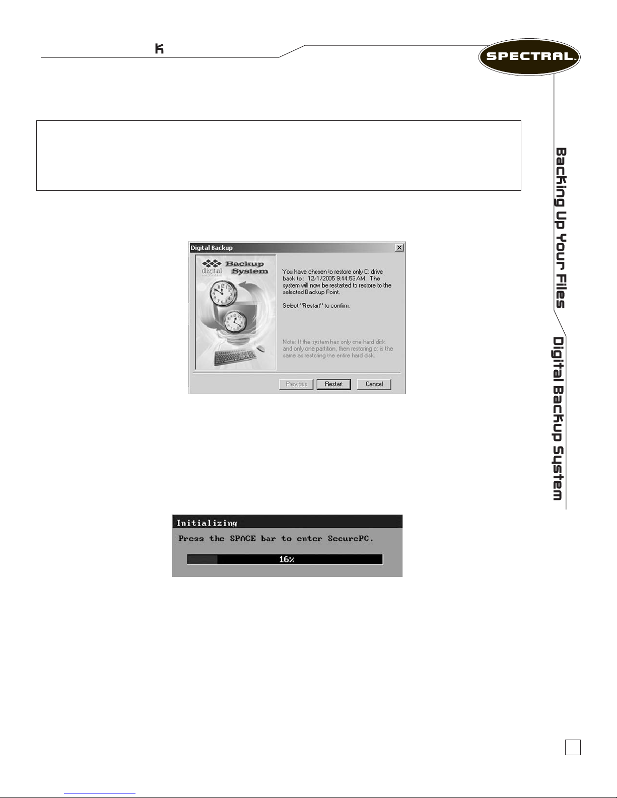
Choosing this option, you can quickly revert your computer to the most recently created Incremental
Backup Point. Click the Restore Your Computer button. The restoration dialog box will appear and
ask you to choose whether to restart your computer.
The Digital Backup System Manager in Real Mode
(Proprietary, non-Windows, independent of Windows operating system)
Activating the Digital Backup System Manager
To activate Digital Backup System program, press the Space Bar after system POST (Power-onself-testing, before Windows begins to load while the pop-up window is displayed.)
File-level Restore
This function is not supported in this version.
The Musician’s PC
TM
14
Page 18
User Manual
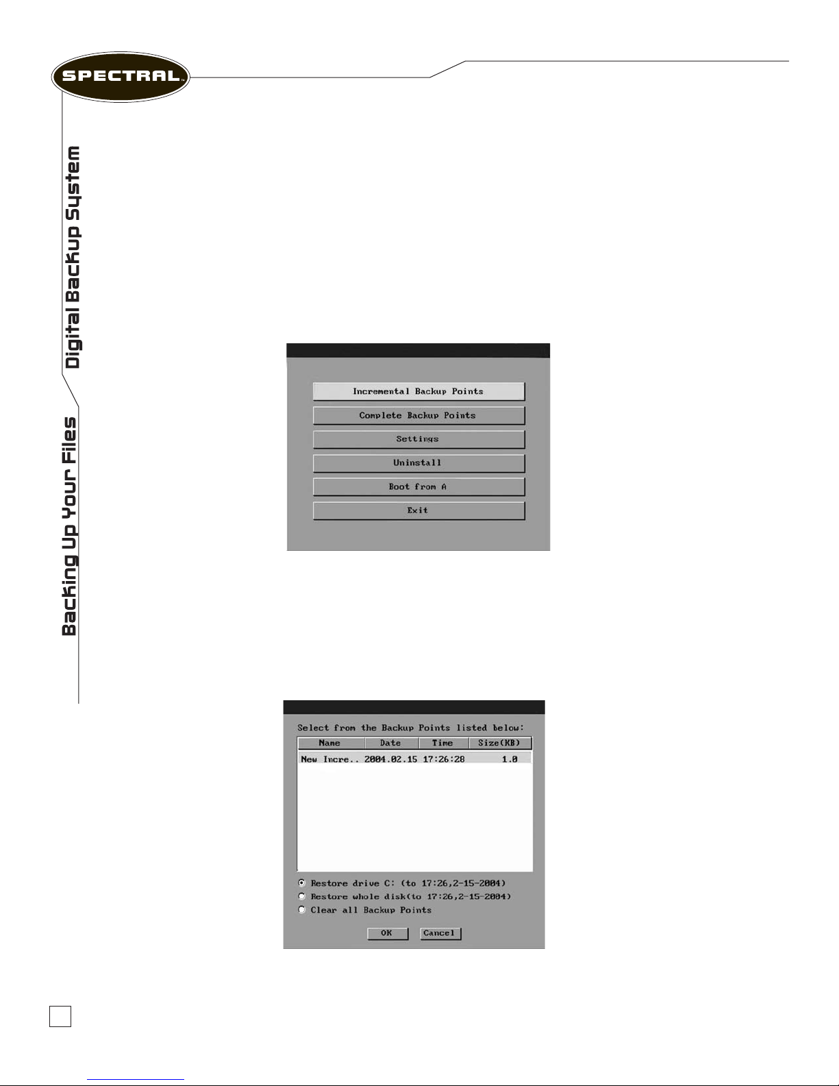
Navigating in the Digital Backup System Manager
1. To activate the Digital Backup System Manager program, press the Space Bar after system
POST (Power-on-self-testing), but before Windows begins to load.
2. Enter your password and press Enter to access the main screen of the Digital Backup System
Manager. (If no password has been entered, the password menu will not be shown.)
3. Navigating in the Digital Backup System Manager DOS screen
•Use the
•Use the
•To make a selection or change an option, press Enter.
4. Using Digital Backup System Manager
Tab key to move through the screen selections. The selected option will be highlighted.
Down Arrow key to highlight Backup Points.
Each of the Digital Backup System Manager buttons is in the following pages.
Incremental Backup Points
This option displays a list of all Incremental Backup Points. The rst available Backup Point will be
the time at which Digital Backup System was last loaded onto your system. From here you can
choose whether to restore the entire hard drive or the C: drive only.
15
www.spectralcomputers.com
Page 19
Rackmount Systems
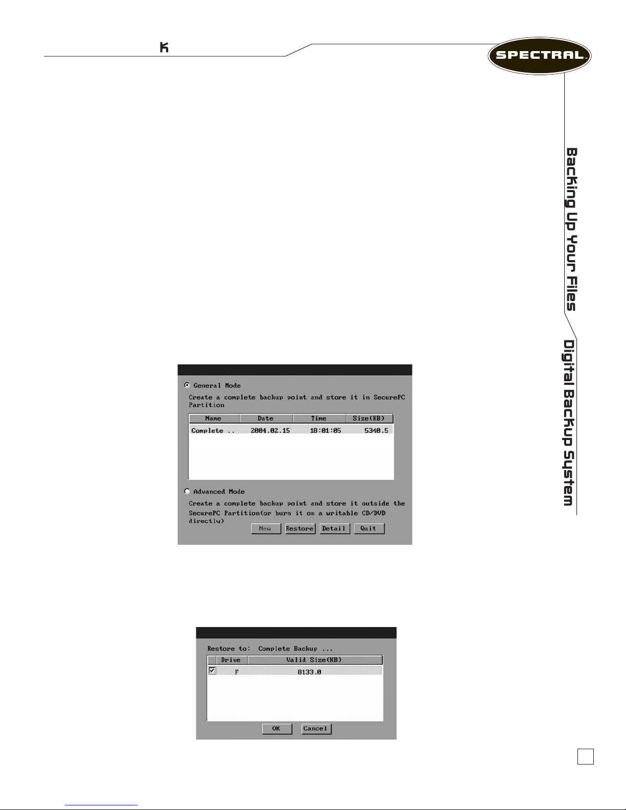
Using the arrow key, move to an appropriate Backup Point and press Enter to complete the
selection. Tab down to OK and press Enter to activate the Digital Backup System restoration
process. A complete restore can take from 20 seconds up to 10 minutes, depending on the
number of les affected. Once the system has restarted, your PC will be restored to the chosen
restoration point. All le modications and additions made after the Backup Point date will be
cleared and any les removed or damaged on your system that existed prior the creation of the
Backup Point will be restored.
Note: If you choose Clear All Backup Points and press OK, once the system has restarted, all original
existing Incremental Backup Points will be cleared and your system will create a new Incremental Backup
Point automatically. (The original Complete Backup Point will still exist. Only one Complete Backup Point
may be created in Digital Backup System.)
Complete Backup Points
There are two options in the Complete Backup Points dialog: General Mode and Advanced.
Reverting a Complete Backup Point
You can revert to a Complete Backup Point, which is created in General Mode, by selecting the
General Mode radio button.
Using the arrow key, move to an appropriate Complete Backup Point and press Enter to complete the
selection. Tab down to OK and press Enter to activate the Digital Backup System restoration process.
The Detail page shows detailed information on the selected Complete Backup Point.
The Musician’s PC
TM
16
Page 20
User Manual
Creating/Restoring an advanced Complete Backup Point in Real Mode
Not supported in this version.
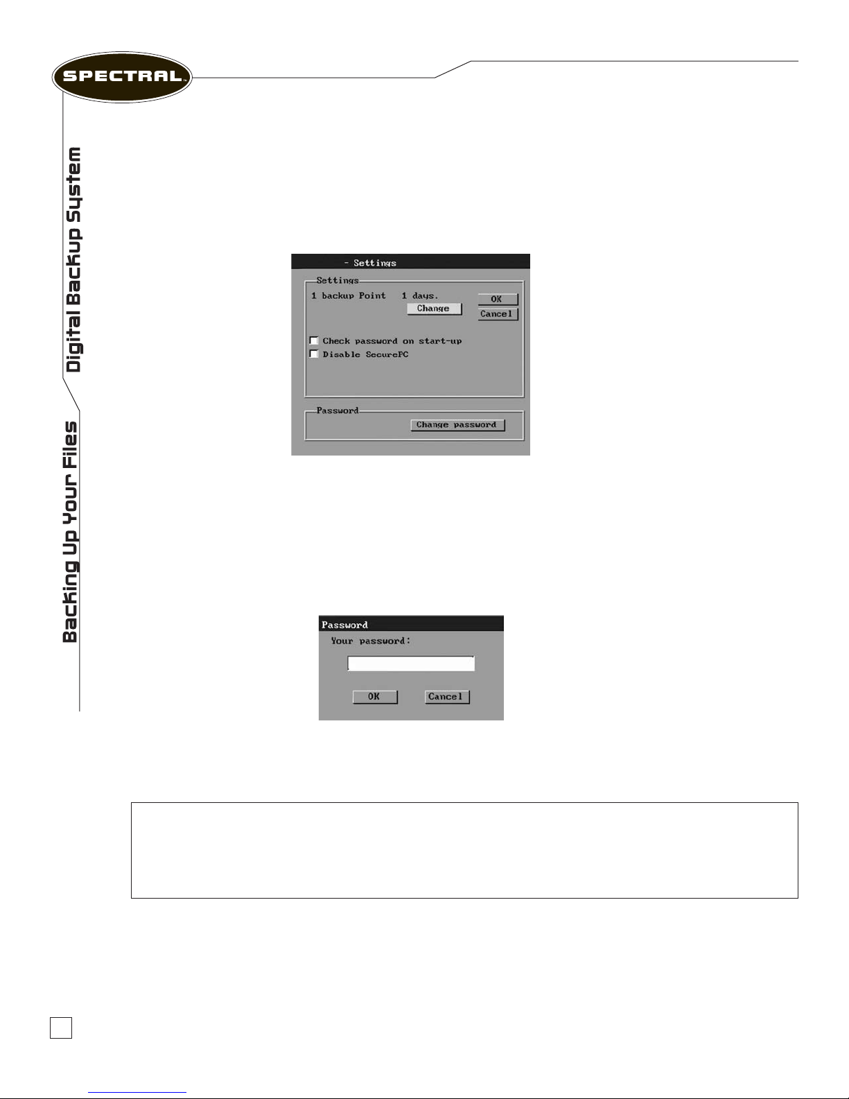
Digital Backup System Schedule Settings
The Digital Backup System Settings window provides several options to manage your
backup strategy.
Settings › Change: This function allows you to set a time period for the automatic
creation of Backup Points. Real Mode can set a Backup Point period between one and 30 days
for each Backup Point.
Password › Changing Password: The options setup provides a convenient way of
Enabling or Disabling Digital Backup System and maintaining your password.
Uninstall
This option allows you to completely remove the Digital Backup System from your system.
All disk space held by Digital Backup System will be released.
CAUTION: Choosing this function will completely remove the backup system from your
computer, and could cause your windows to need reloading. Also, your user license does not
include an installation disk which would allow you to reload the Digital Backup System. This
backup system can only be shipped pre-installed on a hard drive with a new computer system.
Boot from A: not available
Exit
This option allows you to exit from the Digital Backup System Manager program.
17
www.spectralcomputers.com
Page 21
Rackmount Systems
Registering Your PC
Please take a moment to register your new Spectral PC. Registration allows you to take full
advantage of Technical Support, notice of Spectral proprietary software patches, notication
of new products and additional benets that are not extended to non-registered owners.
The registration process takes just a few minutes on the Internet, and your personal information
will never be sold or used for marketing purposes.
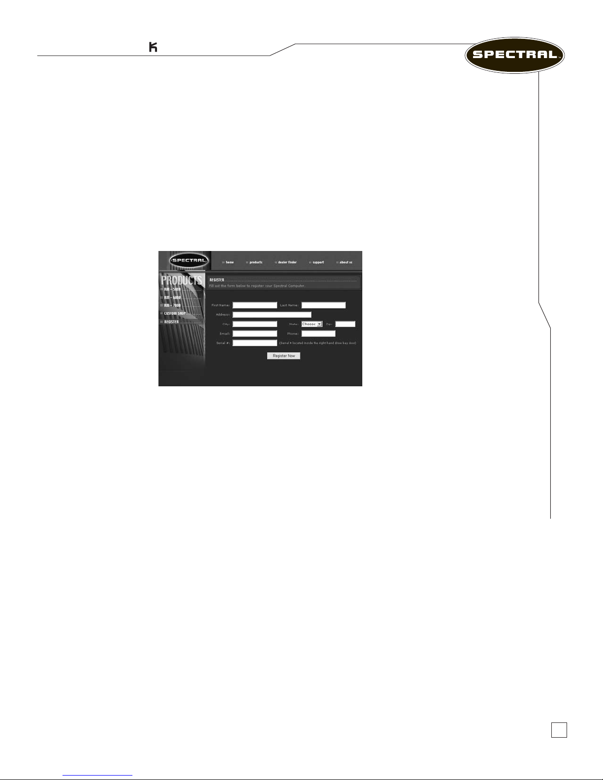
To register your Spectral PC, please go to the Spectral website: www.spectralcomputers.com.
Click on the “Product Registration” icon on the product page.
Registering Your PC
Registration Instructions
When the registration form appears, ll out the information as appropriate. All spaces must be
completed in order to complete the registration process.
When asked for the Spectral Registration Number, please open your Spectral PC’s right door.
A sticker will be afxed to the inside of the door and will have your registration number printed
on it. Type in this number as requested on the online registration form.
When the form is complete, click on the “Submit” button to nish the process.
Congratulations! You are now a fully-registered Spectral Owner!
The Musician’s PC
TM
18
Page 22

Warranty
User Manual
Warranty Information
Limited Warranty
Subject to the limitations set forth below, Digital Corporation hereby represents and warrants that the components
of SPECTRAL computers shall be free from defects in workmanship and materials, subject to normal use and service,
for a period that is one year from the date of shipment of the SPECTRAL computers (such periods being hereinafter
referred to as the “Warranty Period”). The sole and exclusive remedy of the foregoing limited warranty shall be
limited to the repair or replacement of any defective or non-conforming component exclusively by Digital Corporation.
Any and all warranties set forth above or otherwise made by Digital Corporation are conditioned upon proper use
of the SPECTRAL computers in the application for which it is intended and shall not apply to any SPECTRAL computer
(i) that has been modied in any respect without the prior written consent of Digital Corporation, (ii) that has been
installed, serviced or repaired by anyone other than Digital Corporation and/or Digital Corporation’s authorized
personnel, without the prior written approval of Digital Corporation, (iii) has been subject to unusual physical or
electrical stress, or (iv) that has been damaged by reason of accident, neglect, misuse, air conditioning, humidity
control, transportation, extreme heat or cold temperature, failure of electrical power, inappropriate operating
environment or conditions, or failure to comply with applicable operating and maintenance instructions or any
cause other than ordinary use. Digital Corporation hereby agrees to provide technical support limited to hardware
at no cost during the Warranty Period. NEITHER DIGITAL CORPORATION NOR ANY OF ITS RESPECTIVE
LICENSORS, OR AUTHORIZED DEALERS WARRANT THAT THE SPECTRAL COMPUTERS WILL OPERATE
UNINTERRUPTED OR ERROR FREE. CUSTOMERS ARE SOLELY RESPONSIBLE FOR THE SELECTION OF
THE PRODUCTS AND SOFTWARE TO ACHIEVE INTENDED RESULTS FOR PARTICULAR APPLICATIONS.
Warranty Information
Warranty Limitations and Exclusions
All warranties including, but not limited to, the express warranty and the implied warranties of merchantability and
tness for a particular purpose are limited to the Warranty Period. Some states do not allow limitation on how
long an implied warranty lasts, so the above limitation may not apply to you. There are no express warranties
beyond those stated here. In the event that applicable law does not allow the limitation of the duration of the
implied warranties to the Warranty Period, then the duration of the implied warranties shall be limited to as long
as is provided by applicable law. No warranties apply after that period.
Limitations of Liability
Digital Corporation’s responsibility under this, or any other warranty, implied or express, is limited to repair or
replacement, as set forth above. These remedies are the sole and exclusive remedies for any breach of warranty.
Neither Digital Corporation or retailer is responsible for indirect, special, incidental, or consequential damages
resulting from any breach of warranty or under any other legal theory including, but not limited to lost prots,
downtime, goodwill, damage to or replacement of equipment and property, and any costs of recovering, reprogramming,
or reproducing any program or data stored in or used with this system. Some jurisdictions do not allow the exclusion
or limitation of incidental or consequential damages, so the above limitations or exclusions may not apply to you.
This limited warranty gives you specic legal rights, and you may also have other rights that vary from jurisdiction
to jurisdiction.
Mailing Address: Spectral Computers
4858 Van Nuys Blvd.
Sherman Oaks, CA 91403
U.S.A.
Note: Spectral Computers are manufactured and serviced by Digital Corporation.
19
www.spectralcomputers.com
Page 23

Rackmount Systems
Technical Support
Phone No: 818.981.3101
Fax No: 818.981.3102
E-mail:
Web Site:
Hours of Operation: Weekdays 9:30 am – 6:00 pm PST
Mailing Address: Spectral Computers
4858 Van Nuys Blvd.
Sherman Oaks, CA 91403
U.S.A.
[email protected]
www.spectralcomputers.com
Technical Support
Support
The Musician’s PC
TM
20
Page 24

www.spectralcomputers.com
All trademarks and registered trademarks mentioned herein are recognized as the property of their respective holders.
Made in the U.S.A.
0511-7533
 Loading...