

Page 1
SDI
SPECTRADYNAMICS, INC.
PULSE DISTRIBUTION AMPLIFIER
PD-5
OPERATING MANUAL
SPECTRADYNAMICS, INC • 1849 Cherry St. Unit 2. • Louisville, CO 80027
Phone: (303) 665-1852 • Fax: (303) 604-6088
www.spectradynamics.com
Page 2

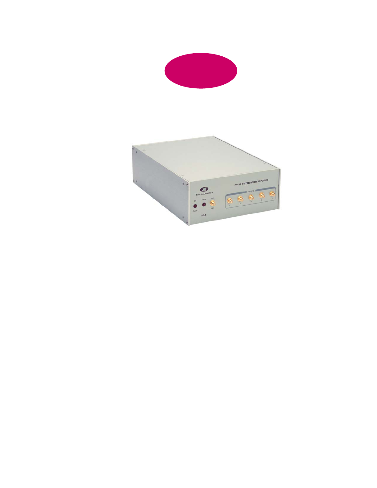
PD-5 Description
SDI
The PD-5 is a TTL pulse distribution amplifier that accepts one input and
provides five outputs. The outputs are designed to drive low impedance loads and long
50 or 75-ohm cables. The propagation delay through the amplifier is typically 10 ns.
The channel-to-channel delay differences are less than 1 ns. The small propagation
delay characteristics and low temperature coefficient of delay are essential for the
distribution of high quality timing signals. The instrument is available in a 3.5” X 8.4” X
12 “ enclosure. The PD-5 can be combined with either a second PD-5 or a one pulse
per second generator model PPS-2 to form a standard 19” rack mountable instrument.
SPECTRADYNAMICS, INC • 1849 Cherry Street, Unit 2 • Louisville, CO 80027 • Phone: (303) 665-1852 • Fax: (303) 604-6088
Se habla español
Copyright © SpectraDynamics, Inc. 2006
1
Page 3

Safety and Preparation for Use
SDI
CAUTION!
Voltages capable of causing injury or death are present in this instrument. Use extreme
caution whenever the instrument cover is removed.
Line Voltage
This instrument may be setup to operate on 100-120 or 220-240 VAC and a line
frequency of 50 to 60 Hz. Locate the power entry module and disconnect the power
cord. The voltage of operation is displayed on the power entry module. If it reads 115
the unit is setup for 100-120 VAC operation. If 230 is displayed the unit is setup for
220-240 VAC operation. To change the line voltage of operation use a flat-blade screw
driver to carefully remove the plastic cover of the power entry connector. The cover
should swing down towards the IEC power socket. Note you cannot change the voltage
setting with the power cord still attached to the unit. Remove the red fuseholder and
rotate to select the desired line voltage. The fuse must be replaced too. Insert the
fuseholder and replace the plastic cover. The selected line voltage setting will be
displayed on the power entry module
Fuse
A 0.5 Ampere 250V slow-blow fuse is used for 100-120 VAC operation.
A 0.25 Ampere 250V slow-blow fuse is used for 220-240 VAC operation.
Only replace fuses with the same type and specifications.
Line Cord
The instrument has a detachable, three wire power cord for connection to a grounded
power source. The enclosure of the unit is directly connected to the outlet ground to
protect against electrical shock. Always use an outlet with a protective ground and do
not disable this safety mechanism.
Service
Do not attempt to service or adjust the instrument unless another person, capable of
providing first aid or resuscitation, is present. Contact SDI for any questions or repairs.
Operation
To operate the unit, locate the AC power entry connector on the rear panel and connect
the power cable. When power is applied to the unit, a red led located on the front panel,
labeled “on”, should light up.
Copyright © SpectraDynamics, Inc. 2006
2
Page 4

The Front Panel
SDI
On The led is on when power is applied to unit and the unit is operating
properly.
1PPS LED The LED will flash on the falling edge of the 1 PPS output signal.
1 PPS Pulse input. The input signal should conform to TTL levels.
Input
Outputs Distribution amplifier output. The outputs are designed to drive 50 ohm
cables. The outputs provide a 2 volt peak-to peak signal into a 50 ohm
load.
Copyright © SpectraDynamics, Inc. 2006
3
Page 5

The Back Panel
SDI
AC POWER ENTRY MODULE
The PD-5 is configured to operate on:
___ 100-120 VAC
___ 220-240 VAC.
Copyright © SpectraDynamics, Inc. 2006
4
Page 6

Operation
SDI
Make sure that the line voltage selection is correct and connect the power cord. If the
line voltage is incorrect please refer to the Safety and Preparation for Use section. Plug
the unit into an appropriate power outlet and turn on the power switch. A red LED on
the front panel will turn on. Attach a cable with the signal to be distributed to the front
panel connector labeled 1 PPS Input. A red LED on the front panel will flash on the
falling edge of each output pulse.
Although the device was designed to distribute precision one pulse per second
signals, it may be used to distribute pulses up to a frequency of 100 MHz. The
propagation delay is under 12 ns, and the channel to channel delay difference is less
than 1 ns.
To operate the unit, locate the power entry module on the rear of the enclosure.
Copyright © SpectraDynamics, Inc. 2006
5
Page 7

Specifications
SDI
The rise and fall times were tested with a TTL input signal at 100 kHz.
PARAMETER CONDITIONS MIN TYP MAX UNITS
Rise time 10 - 90 % - 3 4 ns
Fall time 10 - 90 % - 3 4 ns
Propagation delay 50 ohm load - 10 12 ns
Differential delay Channel - Channel 200 500 ps
Impedance input
output
Input High Level
Input Low Level
Output High Level
Output Low Level
Temperature-delay
Coefficient
Input signal into 50 ohm load
Input signal into 50 ohm load
50 ohm load
50 ohm load
0 - 50 ºC
25 - 35 ºC
50
10
2
-0.7
2
3 3 5 ps/ºC
-
-
2.4
0.4
Ohms
5
0.8
-
0.5
V
V
Copyright © SpectraDynamics, Inc. 2006
6
Page 8

Warranty
The PD-5 is warranted to be free of defects under normal operating conditions, as
specified, for one year from date of original shipment from SpectraDynamics, Inc (SDI).
SDI’s obligation and liability under this warranty is expressly limited to repairing or
replacing, at SDI’s option, any product not meeting the said specifications. This
warranty shall be in effect for one (1) year from the date an PD-5 is sold by SDI. SDI
makes no other warranty, express or implied, and makes no warranty of the fitness for
any particular purpose. SDI’s obligation under this warranty shall not include any
transportation charges or costs of installation or any liability for direct, indirect, or
consequential damages or delay. Any improper use, operation beyond capacity,
substitution of parts not approved by SDI, or any alteration or repair by others in such
manner as in SDI’s reasonable judgement affects the product materially and adversely
shall void this warranty. No employee or representative of SDI is authorized to change
this warranty in any way or grant any other warranty.
SDI
SDI
SPECTRADYNAMICS, INC • 1849 Cherry Street, Unit 2 • Louisville, CO 80027 • Phone: (303) 665-1852 • Fax: (303) 604-6088
Copyright © SpectraDynamics, Inc. 2006
Se habla español
7
Page 9

PD-1I-5O/R01
 Loading...