

Page 1
SPECTRADYNAMICS, INC
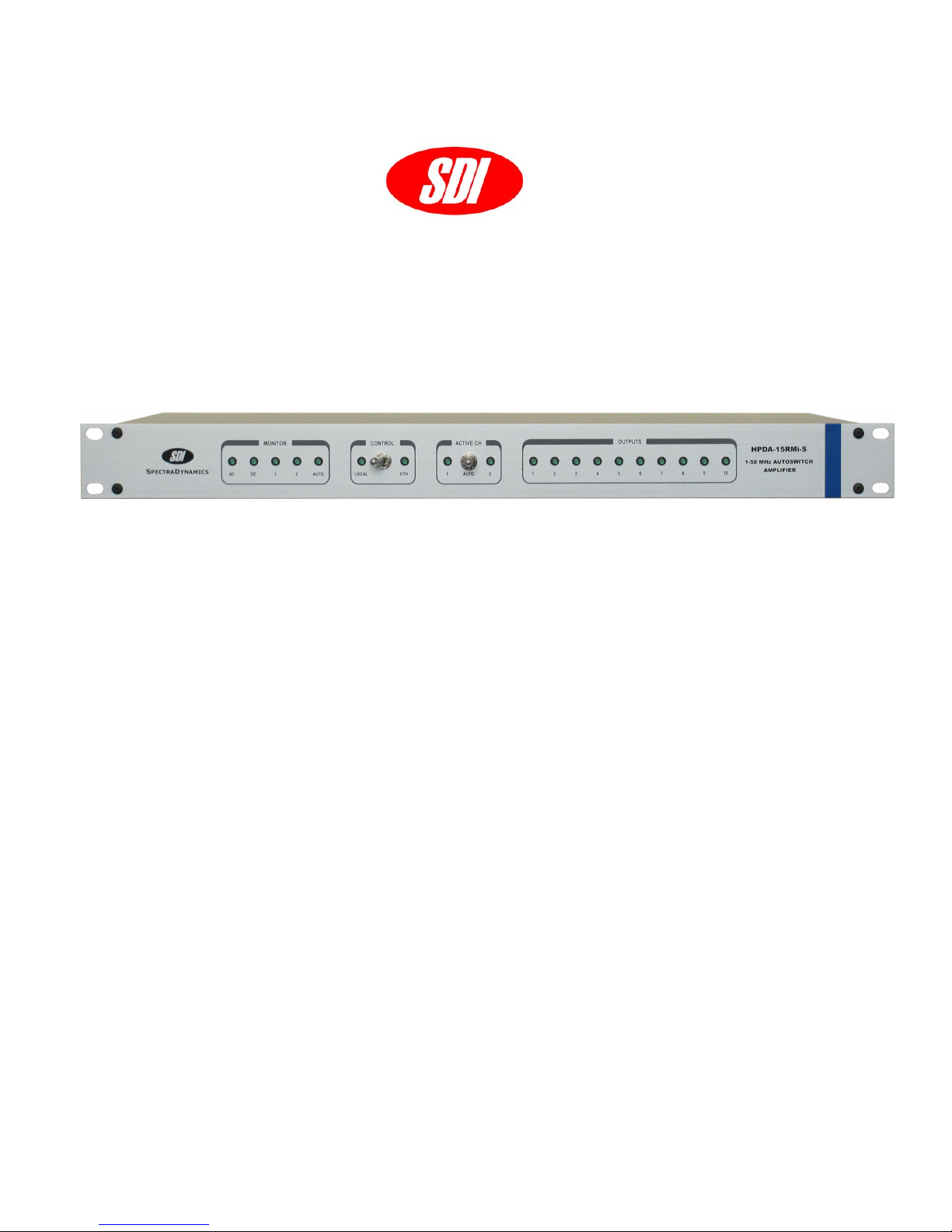
HPDA-15RMi-S
1-50 MHz AUTOSWITCH AMPLIFIER
OPERATING MANUAL
SPECTRADYNAMICS, INC • 1849 Cherry St. Unit 2. • Louisville, CO 80027
Phone: (303) 665-1852 • Fax: (303) 604-6088
www.spectradynamics.com
Page 2

Page 3

HPDA-15RMi-S Operating Manual
Page 4

Contents
1.0 Introduction ……………………………………………………………………... 1
2.0 Safety and preparation for use …………………………………………….. 2
2.1 Electrical safety …………………………………………………………. 2
2.2 Instrument safety …………….………………………………………….. 3
3.0 Front panel description …….………………………………………………… 4
4.0 Back panel description ………………………………………………………. 6
5.0 Installation …………………………………………………………………….. 7
5.1 Connecting power ………………………………………………………… 7
5.2 Connecting RF input signals …………………………………………… 7
5.3 Connecting RF output signals …………………………………………. 8
5.4 Connecting the Ethernet port …………………………………………… 8
5.5 Ethernet port configuration……………………………………………….. 8
6.0 Operation ……………………………………………………………………… 11
6.1 Selecting local or remote mode ………………………………………… 11
6.2 Selecting the active channel …………………………………………… 11
6.3 Remote control commands ……………………………………………… 11
6.4 Alarm monitoring …………………………………………………………. 16
7.0 Troubleshooting ………………………………………………………………. 17
8.0 Specifications …………………………………………………………………. 20
9.0 Warranty and service ………………………………………………………… 21
Page 5

1.0 Introduction
The HPDA-15RMi-S is a high performance frequency distribution amplifier with an auto
switch function that allows the selection of the RF input to be distributed. The selected
RF input supplies 10 buffered unity gain outputs. The instrument has a manual mode and
autoswitch mode of operation. In manual mode, the RF input can be selected with a
toggle switch on the front panel, or by sending a command through the Ethernet
interface. In autoswitch mode the two RF input levels are monitored and compared to a
set threshold of +7 dBm. Upon failure of a selected input channel the amplifier switches
over to the alternate RF input with a switching time less than 1 us.
The selected RF input is buffered and distributed to ten unity gain outputs. The typical
cross-channel isolation of the RF distribution module is 130 dB and reverse isolation is
typically greater than 140 dB. The phase noise of the modules is exceptionally low,
typically –147 dBc/Hz @ Fourier frequency of 1 Hz and –170 dBc/Hz @ Fourier
frequencies greater than 10 kHz. Both the input and output are matched to 50 ohms to
obtain better than 25 dB return loss. All outputs are AC coupled and the grounds are DC
isolated to reduce the effect of ground loops.
The HPDA-15RMi-S is designed to be powered by a 100 to 240 VAC mains source or by
a +12 to +36 VDC power source. The DC power supply may be used as a main power
source for the instrument or in conjunction with the AC power supply as a backup in case
of loss of the main AC power. The instrument is designed to automatically switch from
AC to DC supply operation using a Schottky diode network and charge storage
capacitors to avoid any glitches and ensure uninterrupted continuous operation.
Page 1
Page 6

2.0 Safety and Preparation for Use
The HPDA-15RMi-S was designed for indoor use only and is not intended for operation
outdoors or in a wet environment. The instrument may be mounted in a standard 19-inch
instrumentation rack or may be used on a laboratory bench. Inspect the instrument and
power cords for damage before first use.
2.1 Electrical Safety
Voltages capable of causing injury or death are present in this instrument. Use
extreme caution whenever the instrument cover is removed.
Line Voltage
This instrument is designed to operate with a 100 to 240 VAC, 47 to 63 Hz power source.
This instrument is also capable of operating with a DC power source that can supply +12
to +36 VDC at + 2 Amperes.
Fuse
A 1.0 Ampere 250V 5X10mm slow-blow fuse is used for 100-240 VAC operation.
A 2.0 Ampere 250V 5X10mm slow-blow fuse is used for the DC power protection.
Only replace fuses with the same type and specifications.
AC Power
The instrument has a detachable three wire power cord for connection to a grounded AC
power source. The enclosure of the unit is directly connected to the outlet ground to
protect against electrical shock. Always use an outlet with a protective ground and do not
disable this safety mechanism. Detaching the AC power cord is the only option of
disconnecting the unit from the AC mains supply. Make sure you have access to the rear
panel or provide an external accessible AC disconnect means for your HPDA-15RMi-S.
DC Power
The instrument has a DC connector on the back panel with the following configuration:
Pin 1 NC
Pin 2 NC
Pin 3 NC
Pin 4 +12 to +36 VDC power return
Pin 5 +12 to +36 VDC power
Pin 6 Chassis GND /Earth GND
Page 2
Page 7

2.0 Safety and Preparation for Use
Verify that the connector from your DC power supply has the pin configuration mentioned
above. Do not apply AC voltage to the DC power connector. Failure to follow these
directions may cause injury or death to personnel, cause irreparable damage to the
instrument and voids all warranties.
Please note that the power return (pin 4) is NOT connected to the instrument case
ground internally, however both ground connections (pin 4 and pin 6) are available at the
DC power connector and may be connected together at this point. The requirements for
the external DC power supply are +12 to +36 VDC at 2 Amperes. The following
specifications should be used to ensure the optimum performance for your HPDA-15RMi
-S:
DC Supply voltage +12 to +36 VDC, 2 Amps
Line regulation +/- 0.05% for a 10% line change
Load regulation +/- 0.05% for a 50% load change
Output ripple < 5mV peak-to-peak
2.2 Instrument Safety
The HPDA-15RMi-S is designed to distribute RF signals with a frequency of 1 to 50 MHz .
Input and output levels below +7 dBm will trigger a fault condition which can be monitored
from the front panel as well as through the Ethernet interface. The recommended level for
the RF input signal is +13 dBm +/- 2 dB .
Input signals must be kept below +20 dBm as greater power levels will damage the unit
and void all warranties.
The HPDA-15RMi-S RF outputs are DC isolated from the chassis ground to prevent
ground loops. These outputs are rated to a maximum of +50 V.
Absolute Maximum Ratings
Input RF Power +20dBm Maximum
Reverse RF Power +20dBm Maximum
Voltage at the RF Input +50 V Maximum
Voltage at the RF Output +50 V Maximum
Page 3
Page 8

3.0 Front Panel Description
MONITOR AC
The AC Power LED is on when AC power is applied to unit.
MONITOR DC
The DC Power LED is on when DC power is applied to unit.
MONITOR 1
The Input 1 LED is on when the signal applied to the INPUT 1 connector on the rear panel
has a level greater than +7 dBm.
MONITOR 2
The Input 2 LED is on when the signal applied to the INPUT 2 connector on the rear panel
has a level greater than +7 dBm.
MONITOR AUTO
The AUTO LED will be on when the autoswitch function is enabled..
CONTROL LOCAL/ETH
The locking switch labeled CONTROL is used to select between local front panel control
or remote control via the Ethernet interface. Setting the switch to the LOCAL position
disables the Ethernet remote control functionality but still allows for remote monitoring.
Setting the switch to the ETH position will enable remote control of the instrument through
the Ethernet interface.
ACTIVE CH SWITCH
The ACTIVE CH switch is a locking three position toggle switch that allows the user to
select the active channel from the two possible RF inputs or places the instrument in
autoswitch mode.
Page 4
Page 9

3.0 Front Panel Description
ACTIVE CH 1 LED
The ACTIVE CH 1 LED will be on when INPUT 1 is the active channel.
ACTIVE CH 2 LED
The ACTIVE CH 2 LED will be on when the INPUT 2 is the active channel.
OUTPUTS
There are ten status indicator LEDs one for each output channel. The status indicator LED
will be on if the signal level of that channel is greater than +7 dBm.
Page 5
Page 10

4.0 Back Panel Description
AC POWER
The HPDA-15RMi-S is configured to operate on 100 to 240 VAC.
DC POWER
This instrument may also operate on DC power from +12 to +36 VDC as the main power
supply. When the HPDA-15RMi-S is set up to operate with both AC and DC power
sources at the same time the DC power is used as backup power in case of AC power
outages.
ETHERNET PORT
The Ethernet port on the rear panel allows monitoring of the HPDA-15RMi-S status and
allows selection of the RF input and mode of operation when remote control mode is
enabled.
INPUT1, INPUT2
The RF inputs to the HPDA-15RMi-S labeled INPUT1 and INPUT2 expect a 1-50 MHz
signal with a level greater than +8 dBm and less than +17dBm. The RF input port
impedance is nominally 50 ohms with a return loss of 20dB. A signal level less than
+7dBm on the active channel will cause the instrument to switch over to the alternate input
channel when the autoswitch function is enabled. The active channel may also be
selected by the front panel or by issuing a remote control command.
OUTPUTS
The signal from the active channel is buffered and distributed to the ten SMA output
connectors on the rear panel. These RF outputs are DC isolated from the chassis ground
to prevent ground loops. These outputs are rated to a maximum of +50 V.
Page 6
Page 11

5.0 Installation
5.1 Connecting power
The HPDA-15RMi-S ships with a standard North American or European IEC power cord,
and a Hirose RM12BPE-6S(71) DC power connector. The instrument may be mounted in
a standard 19-inch instrument rack or may be operated on a laboratory bench.
For DC power operation the user must prepare a DC power cable to connect a user
supplied DC power supply to the instrument. The DC power cable can be assembled
using the supplied RM12BPE-6S(71) DC power connector and must have the following
configuration.
Pin 1 NC
Pin 2 NC
Pin 3 NC
Pin 4 +12 to +36 VDC power return
Pin 5 +12 to +36 VDC power
Pin 6 Chassis GND /Earth GND
Once the DC power cable is connected to the DC power supply, plug the Hirose
connector into the instrument mating DC connector on the back panel. Once the DC
supply is turned on the indicator on the front panel labeled DC will turn on.
If AC power operation is desired locate the AC POWER entry module on the rear of the
enclosure and connect the power cord. Plug the unit into an appropriate power outlet. If
you supply AC power to the unit, the LED on the front panel labeled AC will turn on. The
unit can operate using either the AC or DC power. When both AC and DC power are
plugged in the instrument will use the AC supply and only switch over to the DC supply in
case of an AC power failure,
5.2 Connecting RF input signals
There are two RF inputs to the HPDA-15RMi-S one of which will be selected as the active
channel and distributed to the ten output connectors. The RF inputs have a 50-ohm input
impedance. The RF signals should have a frequency between 1 and 50 MHz and a level
between +8 and +17 dBm. RF signal levels less than +7 dBm will trigger a fault condition.
Attach the cable with the first signal to be distributed to the SMA connector on the rear
panel labeled INPUT 1. The corresponding monitor LED labeled 1 on the front panel will
turn on. Attach the second cable carrying the second RF signal to the SMA connector
Page 7
Page 12

5.0 Installation
labeled INPUT 2. The monitor LED labeled 2 will turn on. The monitor LEDs will turn off if
the signal levels drop below +7 dBm.
5.3 Connecting RF output signals
Attach all output RF cables to the SMA output connectors. The RF signal from the active
channel is buffered and distributed to ten SMA connectors on the rear panel. The signal
level on these outputs are monitored and the status is indicated on the front panel. The
LED will be on when the output signals are greater than +7 dBm. A fault on any output
channel will generate an alarm and the corresponding LED will turn off.
5.4 Connecting the Ethernet port
The HPDA-15RMi-S has an Ethernet port which may be used for both monitoring and
control of the instrument using the telnet protocol. Connect the shielded RJ-45 straight
through Ethernet cable from the instrument to an Ethernet jack or hub on your network.
5.5 Ethernet port configuration
The HPDA-15RMi-S is factory configured with an IP address of 0.0.0.0 and DHCP
enabled. With this default setting, the network DHCP server will automatically assign an IP
address, gateway address and subnet mask to the instrument. A static IP address,
gateway and subnet mask may also be assigned to the instrument using the Digi Device
Discovery Tool software that is shipped with the instrument.
To assign a static IP address
1. Install the Digi Device Discovery Tool on a windows computer connected to the same
network as the HPDA-15RMi-S. The software is located in the root directory of the
memory stick that shipped with the instrument.
2. Turn on the power or reset the power to the HPDA-15RMi-S and set the CONTROL
switch on the front panel to the LOCAL position and the ACTIVE CH switch to the 1
position.
3. Run the Digi Device Discovery Tool software tool and click on configure network
settings. All network configuration changes require a password. The password is the
HPDA-15RMi-S serial number and it is case sensitive. In the screen shot below under
Device Tasks only the Configure network settings and Restart device apply to the
HPDA-15RMi-S. The Open web interface link and Telnet to command line do not apply
to the HPDA-15RMi-S. Under the section labeled Details is a list of the network setting
for the device that is selected from the list on the right side of the screen.
Page 8
Page 13

5.0 Installation
Once the Configure network settings link is clicked, the following dialog box will open.
4. Configure the network and record the new network configuration of the instrument:
Page 9
Page 14

5.0 Installation
IP ADDRESS __________________________
GATEWAY __________________________
SUBNET MASK __________________________
MAC ADDRESS __________________________
Click the SAVE button once you are done. The password dialog box will be displayed.
Enter the serial number of the instrument in all capital letters in the password field and click
the OK button.
The new network configuration will be programmed into the HPDA-15RMi-S.
5. If the wrong network configuration is programmed and you can no longer communicate
with the HPDA-15RMi-S, follow the procedure outlined in the Troubleshooting section to
reset the device to the Factory Configuration.
6.1 Selecting local or remote mode
Page 10
Page 15

6.0 Operation
The HPDA-15RMi-S autoswitch amplifier may be operated in local control mode where the
instrument is controlled by the settings on the front panel or in remote mode where the
instrument is controlled by sending commands through the Ethernet interface. The mode
of operation is selected through the locking switch on the front panel labeled CONTROL.
When the switch is in the LOCAL position the instrument can only be controlled through
the front panel. The Ethernet port is still active for monitoring purposes but cannot be used
to change any of the settings of the instrument. Remote mode is selected by moving the
switch to the ETH position. While in remote mode of operation the instrument can only be
controlled through the Ethernet interface.
6.2 Selecting the active channel
The user can select the active channel from the two available input channels. Move the
ACTIVE CH switch to the 1 position to select RF INPUT 1 as the active channel. Move the
ACTIVE CH switch to the 2 position to select RF INPUT 2 as the active channel. The LED
corresponding to the active channel selected will turn on. Moving the switch back to the
center position will activate the autoswitch mode.
In remote mode select RF INPUT 1 as the active channel:
Issue command *IN 1 <cr> where <cr> is a carriage return.
In remote mode select RF INPUT 2 as the active channel:
Issue command *IN 2 <cr> where <cr> is a carriage return.
In remote mode select Autoswitch mode:
Issue command *IN 0 <cr> where <cr> is a carriage return.
6.3 Remote control commands
All commands are CASE sensitive. A carriage return <cr> or linefeed ends the command.
*IN ch <cr> Selects the active channel.
The *IN command allows remote control of the instrument through the Ethernet interface.
The Control switch on the front panel must be set to ETH to enable remote control over the
Ethernet interface. The instrument will return LOCAL MODE if remote control is not
enabled. If remote control is enabled the command executes and the instrument does not
return a response.
ch - remote mode channel parameter { 0, 1, 2}
Page 11
Page 16

6.0 Operation
0 - autoswitch mode
1 - INPUT 1 is active channel
2 - INPUT 2 is active channel
For example:
input: *IN 0<cr>
The instrument is set to autoswitch mode.
*IN? <cr> Query control mode and selected remote mode input channel setting
If the instrument is in LOCAL control mode the remote mode input channel setting may
not match current state of the instrument since it is being controlled by the front panel.
The instrument returns the control mode, cmode and selected remote mode input
channel setting, ch.
cmode ch<cr>
For example:
input: *IN?<cr>
output: ETH 0<cr>
cmode - control mode ETH for ethernet control or LOCAL for local control
ch - remote mode input channel parameter { 0, 1, 2}
0 - autoswitch mode
1 - INPUT 1 is active channel
2 - INPUT 2 is active channel
*SR<cr> Request instrument status.
The instrument will return the command string, the latched control status and the latched
signal status. To clear the latched status and obtain a current status issue the *CL
command and then issue the *SR command.
The control status is a 5-bit hexadecimal number with the following format:
control
MSB Bit 4 1 - DC Power not present
0 - DC Power OK
Bit 3 1 - Remote (Ethernet) control mode
0 - Local control mode
Page 12
Page 17

6.0 Operation
Bit 2 1 - Autoswitch mode enabled
0 - Autoswitch mode disabled
Bit 1 1 - Channel select switch position 2
0 - Channel select switch position 1
LSB Bit 0 1 - Active channel is INPUT 2
0 - Active channel is INPUT 1
signal
MSB Bit 12 1 - AC Power fault
0 - AC Power OK
Bit 11 1 - INPUT 2 signal fault
0 - INPUT 2 signal OK
Bit 10 1 - INPUT 1 signal fault
0 - INPUT 1 signal OK
LSB Bit 0—9 1 - Output channel signal fault
0 - Output channel signal ok
[control] [signal]<cr>
For example:
input: *SR<cr>
output: 22 1<cr>
The command *SR is sent to the standard telnet port 23 at the ip address of the HPDA15RMi-S. The instrument responds with string shown above where the control status is 22
and the signal status is 1.
control = 23 = 16 + 0 + 4 + 2 + 1 = [1] [0] [1] [1] [1]
signal = 0 = 0 + 0 + 0 + 0 + 0 + 0 +0 + 0 + 0 = [0] [0] [0] [0] [0] [0] [0] [0] [1]
The control status returned by the instrument means:
DC power is not present.
The instrument is in local mode of operation.
Autoswitch mode is enabled
Input 2 was selected as the input channel
Input 2 is the currently selected active channel
The signal status means:
Page 13
Page 18

6.0 Operation
AC power is OK
INPUT 2 signal is OK
INPUT 1 signal is OK
Outputs 10 - 2 signal are OK
Output 1 signal fault
*CL<cr> Clear latched status command.
The *CL command clears the latched control and signal status registers. This command
may be used to clear a fault condition after the fault has been corrected. The instrument
does not return any information after this command.
For example:
input: *CL<cr>
*ID<cr> Request identification command.
The *ID command returns the model number and serial number of the instrument. This
command may be used to verify the identity of the device that is being controlled. The
instrument will respond with the command the model number and serial number.
ModelNumber SerialNumber<cr>
For example:
input: *ID<cr>
output:HPDA-15RMi-S 13HP021-01<cr>
*RF<cr> Read Input signal levels command.
The *RF command returns a string with the signal levels for INPUT 1 and INPUT 2 in dBm
units. The signal levels are approximate and the accuracy is +/- 1 dB in the range of –
10dBm to +15 dBm.
For example:
input: *RF<cr>
output:RF1:13.09, RF2:10.20<cr>
*PWR<cr> Read the internal voltage levels of the instrument command.
The *PWR command returns a string with the internal voltage levels of the instrument and
may be used to monitor both the power supply derived from the AC mains as well as the
power from the DC battery backup system. Used to read the internal voltage levels. The
DC values will not be present unless the DC backup power is supplied to the instrument.
Normal values are in the range of 13.8 - 14.8V.
Page 14
Page 19

6.0 Operation
For example:
input: *PWR<cr>
output:AC+:14.376550, AC-:-14.448775, DC+:14.124444, DC-:-14.172626<cr>
HELP<cr> Help command shows all available commands.
For example:
input: HELP<cr>
output: HPDA-15RMi-S Autoswitch Amplifier
Available commands: (type "help <command>" for more info)
*IN - Select active channel
*IN? - Query control mode and remote input setting
*SR - Request instrument status
*CL - Clear latched status
*ID - Request identification
*RF - Read input signal level
*PWR - Read internal voltage levels
ECHO - Turn on or off echoing of characters.
SHOW - Show current configuration.
HELP - This help screen.
ECHO <cr> Echo on/off command . ECHO OFF turns off the echoing of characters.
SHOW ETH0<cr> Show network configuration command.
This command returns network setting of the instrument.For example:
input: SHOW ETH0<cr>
output: Current ETH0 Configuration:
Status: up
IP Address: 192.100.0.156
Netmask: 255.255.255.0
MTU: 1500
Ping Config: off
Ping Config Done: no
DHCP: off
DHCP Config Done: no
6.4 Alarm Monitoring
Page 15
Page 20

6.0 Operation
Front panel control changes and signal status changes are reported through the Ethernet
port. The alarms are reported when the instrument is in either the LOCAL control mode or
REMOTE (ETH) control mode. An alarm string is published to the Ethernet port
automatically. The alarm string has the same format as the status request response.
The format of the ALARM string is:
ALARM [control] [signal]<cr>
The instrument sends the ALARM string, the control status and the signal status.
The control status is a 5-bit hexadecimal number with the following format:
control
MSB Bit 4 1 - DC Power not present
0 - DC Power OK
Bit 3 1 - Remote (Ethernet) control mode
0 - Local control mode
Bit 2 1 - Autoswitch mode enabled
0 - Autoswitch mode disabled
Bit 1 1 - Channel select switch position 2
0 - Channel select switch position 1
LSB Bit 0 1 - Active channel is INPUT 2
0 - Active channel is INPUT 1
signal
MSB Bit 12 1 1 - AC Power fault
0 - AC Power OK
Bit 11 1 - INPUT 2 signal fault
0 - INPUT 2 signal OK
Bit 10 1 - INPUT 1 signal fault
0 - INPUT 1 signal OK
LSB Bit 0—9 1 - Output channel signal fault
0 - Output channel signal ok
Do not attempt to service or adjust the instrument unless another person, capable
Page 16
Page 21

7.0 Troubleshooting
of providing first aid or resuscitation, is present. If there are problems that cannot be
resolved by the troubleshooting steps below please contact technical support.
Technical Support Tel: +1 (303) 665-1852 , Fax: +1 (303) 604-6088
support@spectradynamics.com, www.spectradynamics.com
The threshold for a valid signal is 6.8 dBm when the input signal is decreasing in
amplitude and 7.2 dBm when the input signal is increasing in amplitude.
The switching circuit of the HPDA-15RMi-S has approximately 0.5 dB of hysteresis to
avoid multiple switching events when the amplitude of the input signal is very close to the
threshold. The recommended valid input signal levels are +8 to +15 dBm.
The signal LEDS for channels 1-10 are all ON but the input signal led is OFF.
The INPUT 1 and INPUT 2 leds are OFF when the input signal level is less than +7dBm,
however the output channel monitors may still show a valid signal because the amplifier
has gain of up to +0.5 dB. In addition, if the outputs are not connected to a load the signal
level on the output channels may still be high enough to activate the output channel
monitor LEDs.
AC Power LED does not turn on.
Disconnect all power cords and remove the top cover. Check the main AC power fuse
and power cord. If the fuse is blown replace with same type and rating. Please contact
SDI if the fuse blows again or if the event that caused the fuse to blow is not known.
DC Power LED does not turn on.
Disconnect all power cords and remove the top cover. Check the DC power fuse and
cable assembly and make sure that the power supply is powered on and meets the
required specifications. If the fuse is blown replace with the same type and rating. Please
contact SDI if the fuse blows again or if the event that caused the fuse to blow is not
known.
INPUT LED does not turn on.
The INPUT 1 or 2 signal status LED should be ON for a signal with a frequency in the
range of 1-50 MHz and a level greater than +7 dBm. Check at the end of the RF cable for
the proper level. If the signal meets the required level but the signal LED still shows a fault
the instrument will have to be returned for repair.
Page 17
Page 22

7.0 Troubleshooting
All OUTPUT channel LEDs are off.
Check to see if there is at least one RF input to the instrument with a level greater than +7
dBm. Check that the active channel is set to the input that has the proper signal level.
If the OUTPUT signal status LEDs remain off the instrument will have to be returned for
repair.
One OUTPUT channel LED is OFF the rest are ON.
If the instrument has at least one input signal and the active channel is set to that input, all
the output signal status LEDs should be illuminated. If one of the OUTPUT signal status
LEDs is off, disconnect the output cable from that output channel. If upon disconnecting
the cable from the instrument the status LED is illuminated then there may be a short in
the cable or the load. Check the cable and load for a signal fault. Contact SDI technical
support if the condition persists.
Cannot connect to the instrument through the Ethernet port.
Check the network cable and run the Digi Device Discovery Tool software on a computer
that is attached to the same network as the HPDA-15RMi-S. The software should be able
to locate the HPDA-15RMi-S and display the network setting of the instrument. If the
instrument does not appear in the list of devices on the main screen click the refresh
button. If the error persists try resetting the power on the HPDA-15RMi-S. Check with your
network administrator and make sure that the HPDA-15RMi-S is not blocked by a firewall.
For further assistance contact SDI technical support.
If the instrument is found by the software tool, try opening a telnet session with the
instrument using the displayed network settings on port 23. Type *ID<cr>, the instrument
should respond with its model and serial number.
Unreachable IP address was programmed and cannot connect with the HPDA15RMi-S.
To reset the HPDA-15RMi-S to the factory configuration follow the procedure below.
Disconnect all power cords and remove the top cover.
Page 18
Page 23

7.0 Troubleshooting
Locate connector J1 as shown in the figure below.
You will temporarily short pins 9 and 10 of connector J1 within 5 minutes of powering the
unit to restore the factory settings.
WARNING!!! You will have to connect power to the instrument for the following
steps. Use extreme caution.
Connect power to the unit. Place a shorting jumper across pins 9 and 10 of connector J1.
In the figure above these pins are highlighted by a red rectangle.
Remove the jumper and remove power from the instrument. Replace the top cover of the
HPDA-15RMi-S. The instrument should now be restored to the original factory setting with
DHCP enabled.
Page 19
Page 24

8.0 Specifications
PARAMETER CONDITIONS MIN TYP MAX UNITS
Max Input Level 1 dB compression 17 18 - dBm
Min Input Level no fault 7 8 - dBm
Bandwidth +/- 1 dB 1-50 0.5-65 - MHz
Gain @ 5 MHz - 0 +/- 0.5 dB
Impedance output - 50 - Ohms
Return Loss input(S11) - -25 -20 dB
Return Loss output(S22) - -35 -30 dB
Distortion* +13 dBm - -45 -42 dBc
Isolation output to output
output to input
Isolation input1 to input2 100 110 - dB
Switching time Autoswitch mode - 0.5 1 us
Phase Noise*
(Referred to the Input)
Temperature-delay
Coefficient
1 Hz
10 Hz
100 Hz
>10 kHz
0 - 50 ºC
130
140
-
-
-
-
-
140
145
-147
-157
-167
-171
1.5
- dB
-145
-155
-166
-170
3
dB
dBc/Hz
ps/ºC
*All tests done at 5 MHz and +13 dBm input unless otherwise specified.
Rackmount chassis 1U H, 19“ W, 14” D
Storage temperature -10 to +75 ºC
Operation environment 0 to +50 ºC
Humidity 5% to 95% non-condensing
Page 20
Page 25

9.0 Warranty and Service
WARRANTY
The HPDA-15RMI-S is warranted to be free of defects under normal operating conditions,
as specified, for one year from date of original shipment from SpectraDynamics, Inc (SDI).
SDI’s obligation and liability under this warranty is expressly limited to repairing or
replacing, at SDI’s option, any product not meeting the said specifications. This warranty
shall be in effect for one (1) year from the date a HPDA-15RMI-S is sold by SDI. SDI
makes no other warranty, express or implied, and makes no warranty of the fitness for any
particular purpose. SDI’s obligation under this warranty shall not include any transportation charges or costs of installation or any liability for direct, indirect, or consequential
damages or delay. Any improper use, operation beyond capacity, substitution of parts not
approved by SDI, or any alteration or repair by others in such manner as in SDI’s reasonable judgement affects the product materially and adversely shall void this warranty. No
employee or representative of SDI is authorized to change this warranty in any way or
grant any other warranty.
SERVICE
Do not attempt to service or adjust the instrument unless another person, capable of
providing first aid or resuscitation, is present. Please remember that any alteration or re-
pair may void the warranty. Contact SDI with any questions or to request an RMA if a repair is needed.
SpectraDynamics, Inc.
1849 Cherry Street Unit 2.
Louisville, CO 80027
USA
Tel: (303) 665-1852
Fax: (303) 604-6088
support@spectradynamics.com
www.spectradynamics.com
Page 21
Page 26

HPDA-15RMI-S:R02-2013/FA
 Loading...