

Page 1
1 2 3 4 5 6 7 8 9 10
11 12 13 14 15 16 17 18 19 20
Rear view of the Distribution Module
Pin 1 = GND
Pin 3 = +VDC
Pin 4 = -VDC
SPECTRADYNAMICS
SDI
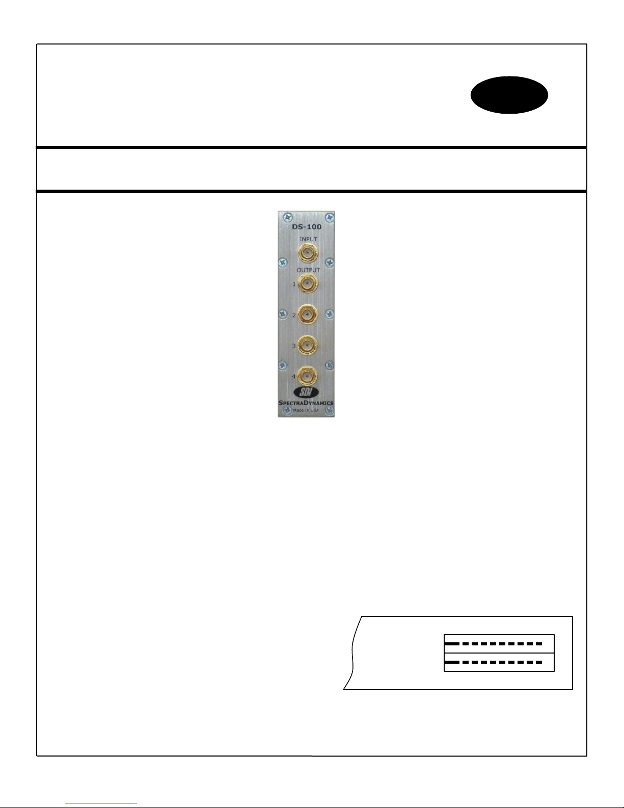
DS-100 Operating Instructions
Description
The DS-100 is a 4 channel distribution and isolation amplifier. Typical cross channel isolation is 70 dB and reverse
isolation is typically greater than 70 dB. The phase noise of the modules is exceptionally low, typically –150 dBc/Hz
@ Fourier frequency of 10 Hz and –170 dBc/Hz @ Fourier frequency greater than 10 kHz. Both the input and output
are matched to 50 ohms to obtain better than 15 dB return loss.
Power Supply
The DS-100 operates on a dual DC power supply. The dual DC power supply should be able to provide 250 mA on
both the positive and negative supply. The DC voltage should be ± 12 VDC. For optimum performance the
following specifications should be used for the power supply.
Positive Supply + 12 VDC, 250 mA
Negative Supply – 12 VDC, 250 mA
Output ripple < 5mV peak to peak
The power supply should have current limiting features as well as over-voltage protection.
WARNING! DO NOT APPLY AC VOLTAGE TO THIS UNIT! Applying AC power to this unit will cause injury or
death to personnel, cause irreparable damage to the instrument and void all warranties.
Copyright © SpectraDynamics, Inc. 2012
Page 2

PARAMETER
CONDITIONS
MIN
TYP
MAX
UNITS
Input Power -
+13
+20
dBm
Bandwidth
+/- 1 dB
+/- 3 dB
80 - 120
1 – 200
MHz
MHz
Gain
@ 100 MHz 0
+/- 1
dB
Input return loss
1-100 MHz 15 dB
Output return loss
1-100 MHz 15 dB
Impedance
input
output
50
50
Ohms
Distortion
+10 dBm
+13 dBm
-40
-40
dBc
100 MHz Isolation
output to output
output to input
50
60
50
60
dB
Phase Noise
10 Hz
100 Hz
10 kHz
-150
-160
-170
-147
-157
-167
dBc/Hz
WARNING! DO NOT REVERSE THE POLARITY OF THE SUPPLY VOLTAGE! Reversing the polarity of the
power supply will cause damage to the unit and void all warranties.
Absolute Maximum Ratings
Input RF power: +20dBm Maximum Reverse RF Power: +20dBm Maximum
DC Voltage on RF input: 10 VDC Maximum DC Voltage on RF output: 50 VDC Maximum
Input Supply Voltage: +/- 15VDC Maximum Storage Temperature: -10 to +75 ºC
Operation Environment: 0 to +50 ºC
WARNING! The maximum differential ground potentials should not exceed the maximum rating of 50VDC,
as this poses a hazard to personnel as well as potentially damaging the output of the amplifier.
Operation
Apply power to the pins 1, 3 and 4 labeled “GND”, “+” and “–” located at the rear of the module. The signal to be
distributed should be connected to the input SMA connector on the module.
Specifications
Warranty
The DS-100 is warranted to be free of defects under normal operating conditions, as specified, for one year from
date of original shipment from SpectraDynamics, Inc (SDI). SDI’s obligation and liability under this warranty is
expressly limited to repairing or replacing, at SDI’s option, any product not meeting the said specifications. This
warranty shall be in effect for one (1) year from the date a DS-100 is sold by SDI. SDI makes no other warranty,
express or implied, and makes no warranty of the fitness for any particular purpose. SDI’s obligation under this
warranty shall not include any transportation charges or costs of installation or any liability for direct, indirect, or
consequential damages or delay. Any improper use, operation beyond capacity, substitution of parts not approved
by SDI, or any alteration or repair by others in such manner as in SDI’s reasonable judgement affects the product
materially and adversely shall void this warranty. No employee or representative of SDI is authorized to change this
warranty in any way or grant any other warranty.
Limitation of Liability
The DS-100 was not developed, and is not licensed, for use in any nuclear, aviation, mass transit, or medical
application or in any other inherently dangerous application. Further, SDI shall not have any liability arising from any
inherently dangerous uses by End-User in any such application. End-User shall indemnify and hold harmless SDI
from and against any and all losses, costs, damages, liabilities or expenses (including attorney’s fees and costs)
arising out of or in connection with the use of the DS-100 by End-User in any such application(s).
Copyright © SpectraDynamics, Inc. 2012
 Loading...