

Page 1

SPECTRACOOL™
Distributed by:
McLean Parts
317-257-6811
5736 N. Michigan Road
Indianapolis, IN 46228
www.mcleanparts.com
Air Conditioner
G28 Model
INSTRUCTION MANUAL
Rev. A
© 2014 Pentair Equipment Protection 89116684
P/N 89116684
Page 2

TABLE OF CONTENTS
Distributed by:
McLean Parts
317-257-6811
5736 N. Michigan Road
Indianapolis, IN 46228
www.mcleanparts.com
RECEIVING THE AIR CONDITIONER ...............................................................................................................................................................................3
HANDLING AND TESTING THE AIR CONDITIONER ......................................................................................................................................................3
HOW TO READ MODEL NUMBERS .................................................................................................................................................................................3
TECHNICAL INFORMATION ............................................................................................................................................................................................4
Sequence of Operation ..........................................................................................................................................................................................................................4
Heating..........................................................................................................................................................................................................................................4
Cooling ..........................................................................................................................................................................................................................................4
Standard and Optional Component Operation .....................................................................................................................................................................................4
Thermostat ...................................................................................................................................................................................................................................4
Remote Access Control (optional) ...............................................................................................................................................................................................4
Head Pressure Control (optional) ................................................................................................................................................................................................4
Contactor (460V Units only) ..........................................................................................................................................................................................................4
Overload (460V Units only) ...........................................................................................................................................................................................................4
Phase Monitor ..............................................................................................................................................................................................................................5
460V to 230V Transformer ............................................................................................................................................................................................................5
115V/230V to 10V Transformer (optional) ....................................................................................................................................................................................5
115V/230V to 24V Transformer and Relay (optional) ...................................................................................................................................................................5
Schematics and Wiring Diagrams for Thermostat Control .................................................................................................................................................................5
4000 BTU 1-Phase Schematic (actual unit options may vary) ....................................................................................................................................................5
6000 BTU 1-Phase Schematic (actual unit options may vary) ....................................................................................................................................................6
G28 Generic 3-Phase Schematic (actual unit options may vary) ...............................................................................................................................................6
4000 BTU 1-Phase Wire Diagram (actual unit options may vary) ..............................................................................................................................................7
6000 BTU 1-Phase Wire Diagram (actual unit options may vary) ..............................................................................................................................................8
DIMENSIONAL DRAWINGS ...........................................................................................................................................................................................10
INSTALLATION INSTRUCTIONS....................................................................................................................................................................................12
REMOTE ACCESS CONTROL (optional) ........................................................................................................................................................................13
Remote Access Control Pin-out ...................................................................................................................................................................................18
DIMENSIONAL DRAWINGS ...........................................................................................................................................................................................24
INSTALLATION INSTRUCTIONS WITH REMOTE ACCESS CONTROL ..........................................................................................................................25
MAINTENANCE .............................................................................................................................................................................................................26
SERVICE DATA ...............................................................................................................................................................................................................31
TROUBLE SHOOTING ....................................................................................................................................................................................................32
WARRANTY ....................................................................................................................................................................................................................38
G28 Generic 3-Phase Wire Diagram (actual unit options may vary) ..........................................................................................................................................9
4000 BTU 115V With Thermostats ......................................................................................................................................................................................................10
6000 and 4000 BTU 230V With Thermostats ......................................................................................................................................................................................11
G28 Generic 460V With Thermostats ..................................................................................................................................................................................................11
INTRODUCTION ...................................................................................................................................................................................................................................13
ENERGIZING THE CONTROLLER........................................................................................................................................................................................................13
CONTROL STATUS INDICATION ..........................................................................................................................................................................................................13
DISPLAYING AND CHANGING PROGRAM VARIABLES ......................................................................................................................................................................14
OPERATING PARAMETERS .................................................................................................................................................................................................................14
ALARM PARAMETERS .........................................................................................................................................................................................................................14
DISPLAYING TEMPERATURE SENSOR #2 .........................................................................................................................................................................................14
COMPRESSOR RESTART TIME DELAY ...............................................................................................................................................................................................14
ALARM OUTPUT CONTACT .................................................................................................................................................................................................................14
ALARM INPUT CONNECTION .............................................................................................................................................................................................................15
ALARM CONDITION DISPLAY..............................................................................................................................................................................................................15
AIR CONDITIONER UNIT COMMUNICATION FEATURES ...................................................................................................................................................................15
USB COMMUNICATION ..............................................................................................................................................................................................................15
ETHERNET COMMUNICATION ..................................................................................................................................................................................................15
USING THE PC INTERFACE TOOL .......................................................................................................................................................................................................16
USB COMMUNICATION MODE ...................................................................................................................................................................................................16
ETHERNET COMMUNICATION MODE .......................................................................................................................................................................................17
Schematics and Wiring Diagrams for Remote Access Control .........................................................................................................................................................19
4000 BTU 1-Phase Schematic (actual unit options may vary) ..................................................................................................................................................19
6000 BTU 1-Phase Schematic (actual unit options may vary) ..................................................................................................................................................19
G28 Generic 3-Phase Schematic (actual unit options may vary) .............................................................................................................................................20
4000 BTU 1-Phase Wire Diagram for Remote Access Control (actual unit options may vary) ............................................................................................... 21
6000 BTU 1-Phase Wire Diagram for Remote Access Control (actual unit options may vary) ............................................................................................... 22
G28 Generic 3-Phase Wire Diagram for Remote Access Control (actual unit options may vary) ...........................................................................................23
4000 BTU 115V With Remote Access Control .....................................................................................................................................................................................24
4000 and 6000 BTU 230V With Remote Access Control .....................................................................................................................................................................24
Compressor .........................................................................................................................................................................................................................................26
Inlet Air Filter .......................................................................................................................................................................................................................................26
How To Remove, Clean or Install a New Inlet Air Filter ..................................................................................................................................................................... 26
Condenser and Evaporator Air Movers ..............................................................................................................................................................................................27
Refrigerant Loss ..................................................................................................................................................................................................................................27
Refrigerant Properties Chart (R 407c) ................................................................................................................................................................................................28
Refrigerant Properties Chart (R 134a) ................................................................................................................................................................................................28
Functional Data....................................................................................................................................................................................................................................29
4000/6000 BTU Unit Characteristics ...................................................................................................................................................................................................30
Components List .................................................................................................................................................................................................................................31
Basic Air Conditioning Trouble Shooting Check List - Thermostat Version .....................................................................................................................................32
Symptoms and Possible Causes - Thermostat Version .....................................................................................................................................................................33
Basic Air Conditioning Trouble Shooting Check List - Remote Access Control Version ..................................................................................................................34
Symptoms and Possible Causes - Remote Access Control Version .................................................................................................................................................36
RETURN AND REPAIR POLICY ...........................................................................................................................................................................................................38
LIMITATION OF LIABILITY ...................................................................................................................................................................................................................39
- 2 -
© 2014 Pentair Equipment Protection
89116684
Page 3
RECEIVING THE AIR CONDITIONER
Distributed by:
McLean Parts
317-257-6811
5736 N. Michigan Road
Indianapolis, IN 46228
www.mcleanparts.com
Inspect the air conditioner. Check for concealed damage that may have occurred during shipment. Look for dents,
scratches, loose assemblies, evidence of oil, etc. Damage evident upon receipt should be noted on the freight bill.
Damage should be brought to the attention of the delivering carrier -- NOT to Pentair Equipment Protection -within 15 days of delivery. Save the carton and packing material and request an inspection. Then file a claim with
the delivering carrier.
Pentair Equipment Protection cannot accept responsibility for freight damages; however, we will assist you in any
way possible.
HANDLING AND TESTING THE AIR CONDITIONER
If the air conditioner has been in a horizontal position, be certain it is placed in an upright, vertical or mounting
position for a minimum of five (5) minutes before operating.
CAUTION
Do not attempt to operate the air conditioner while it is horizontal
or on its side, back or front. The refrigeration compressor is filled
with lubricating oil. This will cause permanent damage to the air
conditioner and also voids the warranty.
TEST FOR FUNCTIONALITY BEFORE MOUNTING THE AIR CONDITIONER TO THE ENCLOSURE.
Refer to the nameplate for proper electrical current requirements, and then wire the unit to a properly grounded
power supply using copper conductors only. Power supply wiring should be restrained after field installation to
ensure no contact with internal fan. Minimum circuit ampacity should be at least 125% of the amperage shown on
the unit nameplate. No other equipment should be connected to this circuit to prevent overloading
Immediately after applying power, the evaporator blower (enclosure air) should start running. Operate the
air conditioner with the compressor running for five (5) to ten (10) minutes. You will need to set the cooling
thermostat or controller setpoint below the ambient temperature to operate the compressor.
Condenser air temperatures should be warmer than normal room temperatures within a few minutes after the
condenser impellers start.
See Sequence of Operation on page 4 for specifics on how the unit operates when powered up.
HOW TO READ MODEL NUMBERS
G28 06 4 6 G150
1 2 3 4 5
1. Identifies the type/family of air conditioner and the approximate height (i.e. G28 = Global family
about 28 inch high).
2. This is the air conditioner’s listed capacity in BTU/Hr. at rated conditions. (i.e. 06=6,000 BTU/Hr. at
131/131 F)
3. 1 = 115 Volt, 2 = 230 Volt, 4 = 460 Volt.
4. 6 = 50/60 Hz or 60 Hz only.
5. Unique set of numbers for each air conditioner which identifies the accessories on a model.
89116684
© 2014 Pentair Equipment Protection
- 3 -
Page 4

TECHNICAL INFORMATION
Distributed by:
McLean Parts
317-257-6811
5736 N. Michigan Road
Indianapolis, IN 46228
www.mcleanparts.com
SEQUENCE OF OPERATION
The air conditioner comes standard with two internally mounted thermostats or remote access control. There
are two modes of operation; heating and cooling. During heating and cooling modes the evaporator fan will be
running.
HEATING
When the enclosure temperature is below the heating thermostat setpoint, power is applied to the
heaters. When the enclosure temperature is 10 degrees above the setpoint the heater is powered off.
COOLING
When the enclosure temperature is above the cooling thermostat setpoint, power is applied through the
thermostat. The compressor is then energized either directly or through a contactor if unit requires one.
The condenser impellers will start immediately if the unit is not equipped with an optional head pressure
control switch. If the unit is equipped with an optional head pressure control switch, the condenser
impellers will start once the refrigerant pressure reaches the setting of the switch. Component specific
information is listed below.
Operating the air conditioner below the minimum ambient temperature or above the maximum ambient
temperatures indicated on the nameplate voids all warranties. DO NOT set the enclosure thermostat to a
temperature lower than 70 F. Doing so can increase the likelihood of frost buildup on the evaporator coil.
The moisture that the enclosure air can contain is limited. If moisture flows from the drain tube
continuously this can only mean that ambient air is entering the enclosure. Be aware that frequent
opening of the enclosure’s door admits humid air that the air conditioner must then dehumidify.
STANDARD AND OPTIONAL COMPONENT OPERATION
THERMOSTAT
The standard G28 air conditioner uses our standard 10-1061-16 thermostat. The thermostat setpoint
equals the temperature that the air conditioner turns off. The thermostat has a 10 F differential from
setpoint until it calls for cooling or heating. An example of operation is shown below.
FOR COOLING (75100 F RANGE):
• Thermostat setpoint = 80 F
• Cooling turns on at 90 F
• Cooling turns off at 80 F
FOR HEATING (5565 F RANGE):
• Thermostat setpoint = 55 F
• Heating turns on at 55 F
• Heating turns off at 65 F
NOTE: For testing purposes only, the thermostat stop screw may be removed (on units so
equipped) to allow settings below 70 F. After testing, replace the stop screw and verify that
the thermostat cannot be set below 70 F. Extended operation below 70 F can cause coil freeze
ups resulting in reduced load and/or unit damage.
REMOTE ACCESS CONTROL (OPTIONAL)
See REMOTE ACCESS CONTROL (optional) on page 13
HEAD PRESSURE CONTROL (OPTIONAL)
Unit is set at the factory, no adjustment necessary.
At a saturated condenser temperature of 85 F (95 psig), the condenser fans will power off. At a saturated
condenser temperature of 118 F (165 psig), the condenser fans will power on.
CONTACTOR (460V UNITS ONLY)
The contactor on this model uses a 230V coil.
OVERLOAD (460V UNITS ONLY)
Set overload reset setting to automatic “A” and trip point dial to 1.6A.
- 4 -
© 2014 Pentair Equipment Protection
89116684
Page 5
PHASE MONITOR
Distributed by:
McLean Parts
317-257-6811
5736 N. Michigan Road
Indianapolis, IN 46228
www.mcleanparts.com
This product is equipped with Phase/Voltage Protection. Please verify correct phasing and voltage before
operating. Note the fans may still operate if phasing is incorrect, but the compressor will not, so the unit
will not cool. Illuminated light on Phase Monitor indicates phase is correct.
If the light is not illuminated, disconnect power from the unit and swap any two power leads at the
terminal block. This should correct the phasing. The light should now illuminate when power is reapplied.
460V TO 230V TRANSFORMER
The 230V from this transformer powers the fans, contactor and optional transformers. 460V is only used
to run the compressor.
115V/230V TO 10V TRANSFORMER (OPTIONAL)
This transformer powers the thermal display on thermostat controlled units only.
115V/230V TO 24V TRANSFORMER AND RELAY (OPTIONAL)
The transformer and relay are used to operate the condenser blower and compressor by using a customer
supplied, remote mounted door switch. This is not a safety door switch, but rather, only helps to reduce
condensation at the evaporator coil if the door is opened. The unit will remain electrified when the door
switch is operated with the evaporator fan continuing to operate, and potentially, if temperatures are low
enough, the heater may continue to operate on outdoor models.
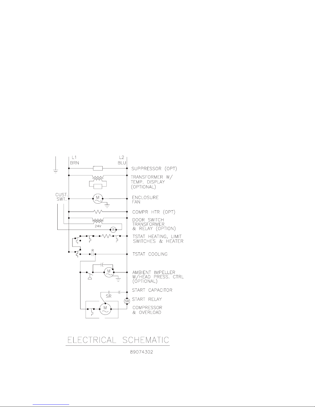
SCHEMATICS AND WIRING DIAGRAMS FOR THERMOSTAT CONTROL
4000 BTU 1PHASE SCHEMATIC (ACTUAL UNIT OPTIONS MAY VARY)
89116684
© 2014 Pentair Equipment Protection
- 5 -
Page 6
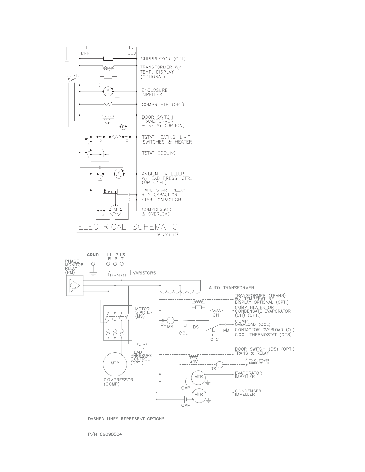
6000 BTU 1PHASE SCHEMATIC (ACTUAL UNIT OPTIONS MAY VARY)
Distributed by:
McLean Parts
317-257-6811
5736 N. Michigan Road
Indianapolis, IN 46228
www.mcleanparts.com
G28 GENERIC 3PHASE SCHEMATIC (ACTUAL UNIT OPTIONS MAY VARY)
- 6 -
© 2014 Pentair Equipment Protection
89116684
Page 7
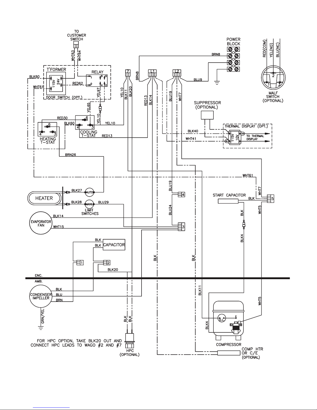
4000 BTU 1PHASE WIRE DIAGRAM (ACTUAL UNIT OPTIONS MAY VARY)
Distributed by:
McLean Parts
317-257-6811
5736 N. Michigan Road
Indianapolis, IN 46228
www.mcleanparts.com
89077284
89116684
© 2014 Pentair Equipment Protection
- 7 -
Page 8
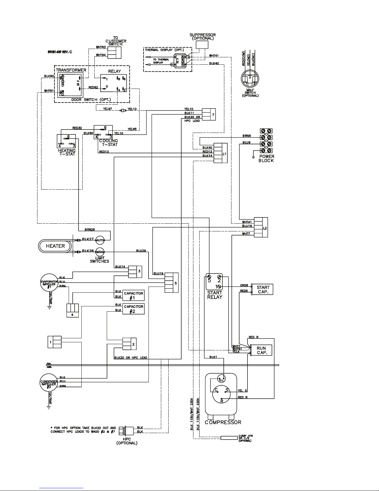
6000 BTU 1PHASE WIRE DIAGRAM (ACTUAL UNIT OPTIONS MAY VARY)
Distributed by:
McLean Parts
317-257-6811
5736 N. Michigan Road
Indianapolis, IN 46228
www.mcleanparts.com
89081439
- 8 -
© 2014 Pentair Equipment Protection
89116684
Page 9

G28 GENERIC 3PHASE WIRE DIAGRAM (ACTUAL UNIT OPTIONS MAY VARY)
Distributed by:
McLean Parts
317-257-6811
5736 N. Michigan Road
Indianapolis, IN 46228
www.mcleanparts.com
89116684
© 2014 Pentair Equipment Protection
- 9 -
Page 10
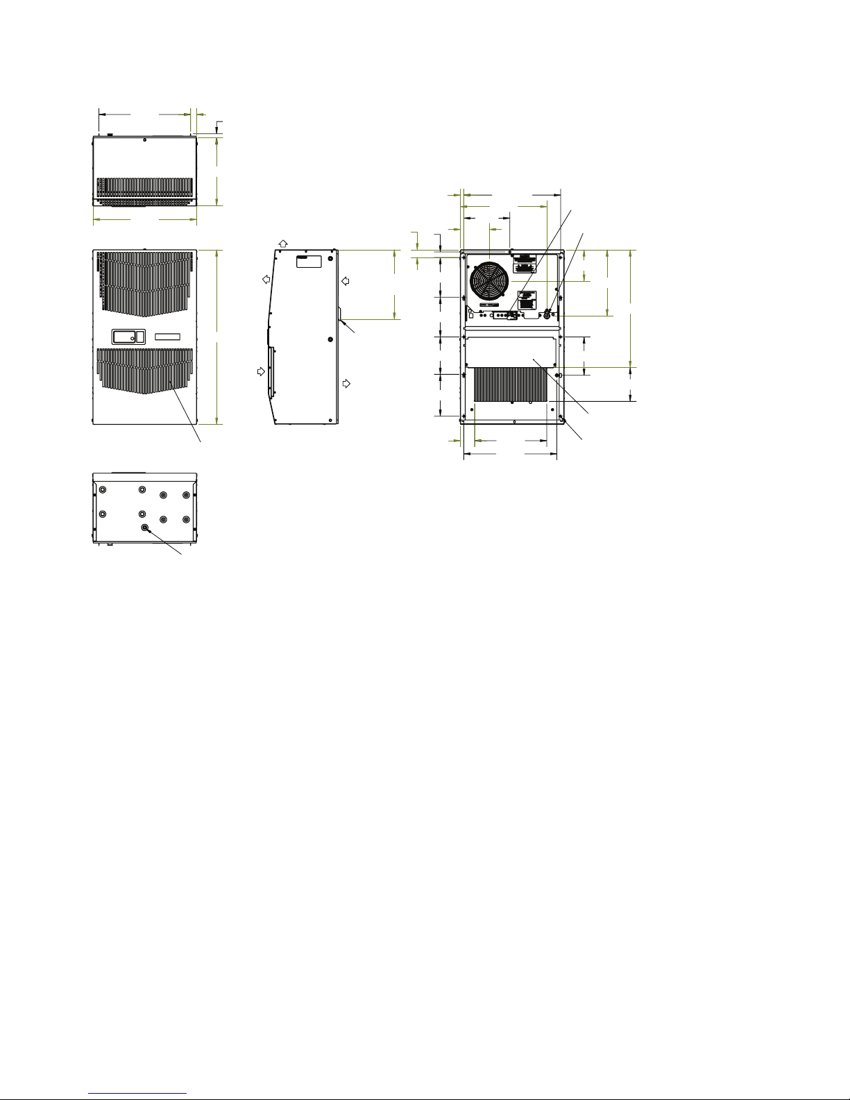
DIMENSIONAL DRAWINGS
Distributed by:
McLean Parts
317-257-6811
5736 N. Michigan Road
Indianapolis, IN 46228
www.mcleanparts.com
4000 BTU 115V WITH THERMOSTATS
89076942
&/($1$%/(5(86$%/(
$/80,180,1/(7),/7(5
%(+,1'5(029$%/(3$1(/
$,5287
$0%,(17
:$50
$,5,1
(1&/2685(
$,5,1
5(029$%/(
+$1*,1*
7$%6
&22/
$,5287
127(
$33529(727<3(5
02817,1**$6.(76833/,('1276+2:1
&22/,1*+($7,1*
7+(50267$76
32:(5,1/(7
237,21$/$&&(663$1(/
21/<)2581,76:,7++($7(5
81&
02817,1*+2/(6
$&&(66+2/(72
2''5$,1678%
- 10 -
© 2014 Pentair Equipment Protection
89116684
Page 11
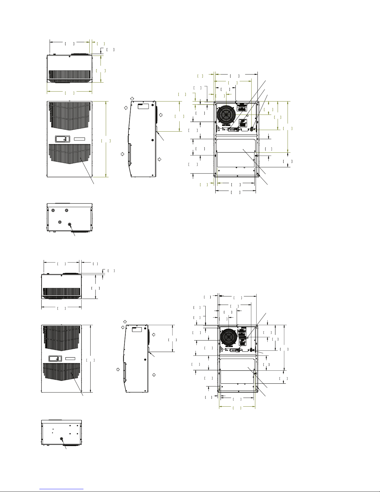
6000 AND 4000 BTU 230V WITH THERMOSTATS
Distributed by:
McLean Parts
317-257-6811
5736 N. Michigan Road
Indianapolis, IN 46228
www.mcleanparts.com
88026303
:$50
$,5287
$0%,(17
$,5,1
&/($1$%/(5(86$%/(
$/80,180,1/(7),/7(5
%(+,1'5(029$%/(3$1(/
127(
$33529(727<3(5
02817,1**$6.(76833/,('1276+2:1
(1&/2685(
$,5,1
5(029$%/(
+$1*,1*
7$%6
&22/
$,5287
+($77+(50267$7
237,21$/
&22/,1*7+(50267$7
32:(5,1/(7
237,21$/$&&(663$1(/
21/<)2581,76:,7++($7(5
81&
02817,1*+2/(6
$&&(66+2/(72
>@2''5$,1678%
G28 GENERIC 460V WITH THERMOSTATS
.98
25
.65
16.6
10.18
258.6
AIR OUT
28.59
726.2
CLEANABLE, REUSABLE
ALUMINUM INLET FILTER
BEHIND REMOVABLE PANEL.
AMBIENT
(2)
WARM
AIR IN
ENCLOSURE
AIR IN
REMOVABLE
HANGING
TABS
COOL
AIR OUT
11.38
288.9
89059479
15.05
382.2
17.01
432.1
165.1
6.13
155.7
.57
14.5
1.26
32.1
.91
23.2
6.50
(2)
6.50
165.1
(2)
6.87
174.5
(2)
1.26
31.9
4.64
117.7
7.55
191.8
14.20
360.6
15.87
403.1
14.00
355.6
15.26
387.6
COOLING THERMOSTAT
5.13
130.2
10.83
275
19.32
490.7
POWER INLET
6.30
160
5.52
140.2
OPTIONAL ACCESS PANEL
(ONLY FOR UNITS WITH HEATER)
1/4-20 UNC (11)
MOUNTING HOLES
NOTE:
APPROVE TO TYPE 3R/4/12.
1.
MOUNTING GASKET SUPPLIED (NOT SHOWN).
2.
ACCESS HOLE TO
.375 [9.5] O.D. DRAIN STUB
89116684
© 2014 Pentair Equipment Protection
- 11 -
Page 12
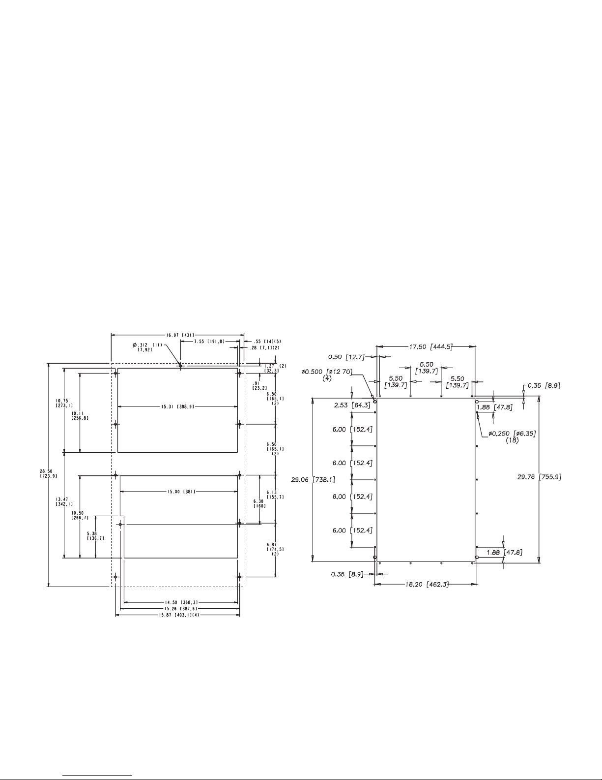
INSTALLATION INSTRUCTIONS
Distributed by:
McLean Parts
317-257-6811
5736 N. Michigan Road
Indianapolis, IN 46228
www.mcleanparts.com
1. Inspect the air conditioner and verify correct functionality before mounting the air conditioner. See
HANDLING AND TESTING THE AIR CONDITIONER on page 3.
2. Using the mounting gasket kit provided with the unit, install gaskets to the air conditioner, see
Figure 1.
3. Mount air conditioner on enclosure taking care not to damage the mounting gasket. The
mounting gasket is the seal between the air conditioner and the enclosure. Avoid dragging the air
conditioner on the enclosure with the mounting gasket attached as this could cause rips or tears
in the gasket and risk losing the water tight seal.
4. Allow unit to remain upright for a minimum of five (5) minutes before starting. CAUTION! Air
conditioner must be in upright position during operation.
5. Refer to the nameplate for electrical requirements. Wire the unit to a properly grounded power
supply. For 3 phase units, once power is applied, verify that phase monitor light is illuminated
which indicates correct electrical phasing. Electrical circuit should be fused with slow blow or
HACR circuit breaker.
6. Some air conditioners require a remote mounted thermostat. Wire the thermostat outputs to the
appropriate terminals on the 24 VAC terminal strip by noting the locations on the correct wiring
diagram.
7. Set thermostat for required cabinet temperature. Refer to Sequence of Operation on page 4 for
thermostat adjustment and operation.
28100013
Surface Mount Partial Recess Mount
- 12 -
Figure 1
Cut-out Drawing
© 2014 Pentair Equipment Protection
89059115
89116684
Page 13
REMOTE ACCESS CONTROL (OPTIONAL)
Distributed by:
McLean Parts
317-257-6811
5736 N. Michigan Road
Indianapolis, IN 46228
www.mcleanparts.com
INTRODUCTION
The Remote Access Control is a parametric controller for the complete management of air conditioners. All
settings are pre-programmed at the factory. Cooling/heating set-points, cooling/heating differential and high /low
temperature alarm set-points can be adjusted by the user. Alarms are outputted through a relay contact and also
can be accessed through an Ethernet connection utilizing SNMP, EtherNet/IP and Modbus TCP. A USB connection
is also provided and can be used to interface with the controller utilizing Modbus RTU.
ENERGIZING THE CONTROLLER
The controller is wired and programmed at the factory to be energized when power is supplied to the air
conditioner.
CONTROL STATUS INDICATION
The display has numerous symbols that indicate if the controller is heating, cooling, alarming, if the compressor
is enabled, and if the ambient fan is enabled. The 3 alpha-numeric characters further describe alarms and show
the cabinet temperature by default.
SYMBOL COLOR ICON ON ICON FLASHING
1 AMBER Compressor On Start-up Request
2,3,4 AMBER Not Used Not Used
A AMBER Compressor On Not Used
B AMBER Evaporator Fan On Start-up Request
C AMBER Not Used Not Used
D AMBER Not Used Not Used
E AMBER Heater Active Not Used
F RED Alarm Active Not Used
G AMBER Controller Active Not Used
H AMBER Not Used Not Used
89116684
© 2014 Pentair Equipment Protection
- 13 -
Page 14

DISPLAYING AND CHANGING PROGRAM VARIABLES
Distributed by:
McLean Parts
317-257-6811
5736 N. Michigan Road
Indianapolis, IN 46228
www.mcleanparts.com
Access: To view and/or change parameters, press and hold the Prg and Sel buttons for greater than 5 seconds.
Press the up or down arrow buttons until “22” is displayed, then press Sel button. When “S-P” is displayed, press
Sel.
Navigation: Press up or down arrows to display sub-menus then press Sel to select the desired sub-menu. In the
sub-menu, use up or down arrows to display parameters for viewing or changing and press Sel. Use Prg button to
back out of menu levels as desired.
Adjust: Use the up or down arrows to change the parameter value then push Sel to save that setting. If Sel is not
pressed, the change to the value will not be saved. Navigate to and change other parameters as desired. When
finished, push Prg to back out of the sub-menus to the main menu.
NOTE: The display will revert to normal temperature display mode if no buttons are pressed
for 60 seconds.
OPERATING PARAMETERS
Parameter Default Value Range Description
r01 80 F 72 F to 120 F Cooling set-point
r02 7 F - Cooling differential
A04 50 F* 32 F to 60 F Heating set-point*
A05 7 F* - Heating differential*
Cooling turns on at r01 + r02, and off at r01
Heating turns on at A04, and off at A04 + A05
*Functional only on units with heater option
ALARM PARAMETERS
Parameter Default Value Description
P16 125 F High Temperature Alarm
P19 40 F Low Temperature Alarm
DISPLAYING TEMPERATURE SENSOR #2
Sensor number 2, the air outlet or condenser coil sensor, can be viewed at any time by pressing the up or down
arrow button on the front panel of the controller display. The display will revert to displaying temperature sensor
number 1 (the AC inlet temperature) after 60 seconds. Both sensors can also be read through the Ethernet and
USB connections.
COMPRESSOR RESTART TIME DELAY
A factory set 6 minute (360 second) restart delay exists to reduce residual back pressure before allowing the
compressor to restart. The compressor will stay off for the entire restart duration after the compressor is
disabled. A flashing “1” on the controller display will indicate the unit is in a compressor restart delay while
calling for cooling.
ALARM OUTPUT CONTACT
The Remote Access Control has a normally open dry contact alarm output with a resistive load rating of 250 VAC
at 3 amps. Two yellow 18 AWG wires located at the back of the air conditioner provide a connection to this output.
- 14 -
© 2014 Pentair Equipment Protection
89116684
Page 15

ALARM INPUT CONNECTION
Distributed by:
McLean Parts
317-257-6811
5736 N. Michigan Road
Indianapolis, IN 46228
www.mcleanparts.com
The Remote Access Control can accept a dry contact/switch input via the two 18 AWG white wires located at the
back of the air conditioner. This input is associated with the controller display alarm mnemonic TP (door open
and/or smoke detected). [To use this feature, remove the splice connector connecting the two white wires and
connect customer supplied enclosure door switch in its place.]
ALARM CONDITION DISPLAY
There are seven possible non-latching alarm conditions detectable by the controller and are indicated on the
controller display. All alarms can also be accessed through the Ethernet and USB connections.
Alarm Mnemonic Description Cause Result Alarm Relay
TP General Alarm
LA
E1
E2
Ht
Lt
A1 Frost Alarm
High Pressure
Warning
Air Inlet Temperature
Sensor Alarm
Air Outlet Temperature
Sensor Alarm
High Temperature
Alarm
Default = 125 F
Low Temperature
Alarm
Default = 40 F
Door open and/or
smoke detected
MALF high pressure
switch opens
Sensor Failure
Sensor Failure
Cabinet over
temperature
Alarm clears at default
setting -2 F
Cabinet under
temperature
Alarm clears at default
setting +27 F
Evaporator coil frozen
Alarm clears at 59 F
Unit turns off for
duration of alarm
No effect on function N/A
Unit turns off for
duration of alarm
Unit turns off for
duration of alarm
No effect on function Relay Contacts Close
No effect on function Relay Contacts Close
Compressor and
Evaporator fan off for
duration of alarm
Relay Contacts Close
Relay Contacts Close
Relay Contacts Close
Relay Contacts Close
AIR CONDITIONER UNIT COMMUNICATION FEATURES
Air conditioner units equipped with communication capabilities provide SNMP, EtherNet/IP and Modbus TCP
protocols through Ethernet and Modbus RTU protocol via USB. Hoffman® Cooling has a PC Interface Tool
available for download that can utilize either mode to communicate with the air conditioner unit.
USB COMMUNICATION
This communication mode allows direct connection of a PC to the air conditioner unit. The protocol
supported is Modbus RTU. Use the PC Interface Tool to communicate with the air conditioner unit. A
MINI-b USB connection is provided.
ETHERNET COMMUNICATION
This communication mode allows remote connection to the air conditioner unit using SNMP, EtherNet/IP
and Modbus TCP protocols. Customers using their own software can download a MIB file for SNMP, EDS
file or EtherNet_IP Object file for EtherNet/IP and Coil_Register file for Modbus TCP.
Note: ACU has a default IP Address of 192.168.1.2
Both Ethernet and USB communication modes allow the ability to:
• Read ACU inlet and outlet air temperatures
• Read and change Cooling Set-point and Cooling Differential
• Read and change Heating Set-point, Heating Differential
• Read and change High and Low Temperature Alarm Settings
• Read and change Gateway IP Address, Device IP Address, Subnet Mask, Trap IP Address and Community
• Read and change Unit Identification
• Read and change the state of IP addressing (static or dynamic)
• Read current Alarm Status
SOFTWARE AND CONFIGURATION FILE DOWNLOADS
The PC Interface Tool, MIB file, EDS file, EtherNet_IP Object file and Coil_Register file can be downloaded
from www.hoffmanonline.com.
89116684
© 2014 Pentair Equipment Protection
- 15 -
Page 16

USING THE PC INTERFACE TOOL
Distributed by:
McLean Parts
317-257-6811
5736 N. Michigan Road
Indianapolis, IN 46228
www.mcleanparts.com
The PC Interface Tool gives the user the ability to communicate with the air conditioner unit to read/write
parameters using either Ethernet or USB connections.
USB COMMUNICATION MODE
NOTE: Before connecting unit to the PC, make note of the comm ports present. After the unit
is connected to the PC, a new comm port will be added to the list. Use this new comm port.
• From Tools menu select Use Ethernet
• When Use Ethernet is unchecked, then Comm Port menu is enabled, Device IP and Community boxes are not
shown, and USB communication can be used
• To set the comm port, choose Comm Port from the Tools menu and then select the comm port from the combo box
VIEWING AIR CONDITIONER UNIT VALUES
To view Air Conditioner Unit values
• Select the ACU Values tab
• Select the Enable Comm button (the PC Interface will now be communicating with unit)
• To stop communication select the Disable Comm button
CHANGING AIR CONDITIONER UNIT VALUES
To change ACU Values
• Select the Settings tab
• Select the value to change
• Make the change to the value
• Select the Change Setting button
• Change can be verified in ACU Values tab
VIEWING AND CHANGING ETHERNET INFORMATION
To view and change Ethernet Information
• Select Ethernet Info tab
To view Ethernet Information
• Click Read Ethernet Info button
To change to dynamically assigning IP Address Mode
• Check Use DHCP Server checkbox
• Enter Trap IP Address and Community
• Click Load Ethernet Info button
To change to statically assigning IP Address Mode
• Uncheck Use DHCP Server checkbox
• Enter Device IP Address, Subnet Mask, Gateway IP Address, Trap IP Address and Community
• Click Load Ethernet Info button
- 16 -
© 2014 Pentair Equipment Protection
89116684
Page 17

ETHERNET COMMUNICATION MODE
Distributed by:
McLean Parts
317-257-6811
5736 N. Michigan Road
Indianapolis, IN 46228
www.mcleanparts.com
• From Tools menu select Use Ethernet
• When Use Ethernet is checked, Comm Port selection is disabled, Device IP and Community boxes are shown and
Ethernet communication can be used.
• Enter unit’s IP Address and Community string in Device IP and Community boxes at the bottom of the PC Interface
Tool.
Each unit has two community strings. One is a Read/Write community string (defaulted to
‘private’) that can be changed by the customer (must be 4 to 8 characters long). The other is a
Read-Only community string (‘public’) and cannot be changed.
VIEWING AIR CONDITIONER UNIT VALUES
To view Air Conditioner Unit values
• Select the ACU Values tab
• Select the Enable Comm button (the PC Interface will now be communicating with unit)
• To stop communication select the Disable Comm button
CHANGING AIR CONDITIONER UNIT VALUES
To change ACU Values
• Select the Settings tab
• Select the value to change
• Make the change to the value
• Select the Change Setting button
• Change can be verified in ACU Values tab
VIEWING AND CHANGING ETHERNET INFORMATION
To view and change Ethernet Information
• Select Ethernet Info tab
To view Ethernet Information
• Click Read Ethernet Info button
To change to dynamically assigning IP Address Mode
• Check Use DHCP Server checkbox
• Enter Trap IP Address and Community
• Click Load Ethernet Info button
To change to statically assigning IP Address Mode
• Uncheck Use DHCP Server checkbox
• Enter Device IP Address, Subnet Mask, Gateway IP Address, Trap IP Address and Community
• Click Load Ethernet Info button
ALARM LOG ACCESSIBLE WITH SNMP
• Using custom software with the provided MIB file gives the ability to view a log of the last 25 alarms
89116684
© 2014 Pentair Equipment Protection
- 17 -
Page 18

REMOTE ACCESS CONTROL PINOUT
Distributed by:
McLean Parts
317-257-6811
5736 N. Michigan Road
Indianapolis, IN 46228
www.mcleanparts.com
FUNCTION NAME PIN # WIRE #
U1 OUTPUTS
ALARM RELAY OUTPUT No5 12 YEL39
ALARM INPUT
CONNECTION
MALFUNCTION NC SWITCH ID2 1 BLU88
DIGITAL INPUT GROUND ID GND 3 BLU
U2 INPUTS
T1, EVAP IN THERMISTOR B1 13 RED
T2, EVAP OUT THERMISTOR B2 12 RED
T1, T2 GND GND 6 WHT
CONTROLLER POWER G 7 BLK40
CONTROLLER POWER G0 14 WHT41
U3 DATA
DIRECTION 3 GREEN
COOL No1 1 ORG78
C1/2 2 BLK
HEAT No2 7 BRN76
C1/2 3 BLK
ENCL MI No3 8 BLK77
C3/4 4 BLK
NA No4 (na) 9 BLK
C3/4 10 BLK
C5 6 YEL38
NA x 5 NA
NA x 11 NA
ID1 8 WHT63
NA ID3 (na) 9 BLU
NA ID4 (na) 2 BLU
NA ID5 (na) 10 BLU
NA Y (na) 4 NA
NA GND (na) 5 NA
NA B3 11 NA
POWER 1 RED
GROUND 2 BLACK
DATA 4 WHITE
- 18 -
© 2014 Pentair Equipment Protection
89116684
Page 19
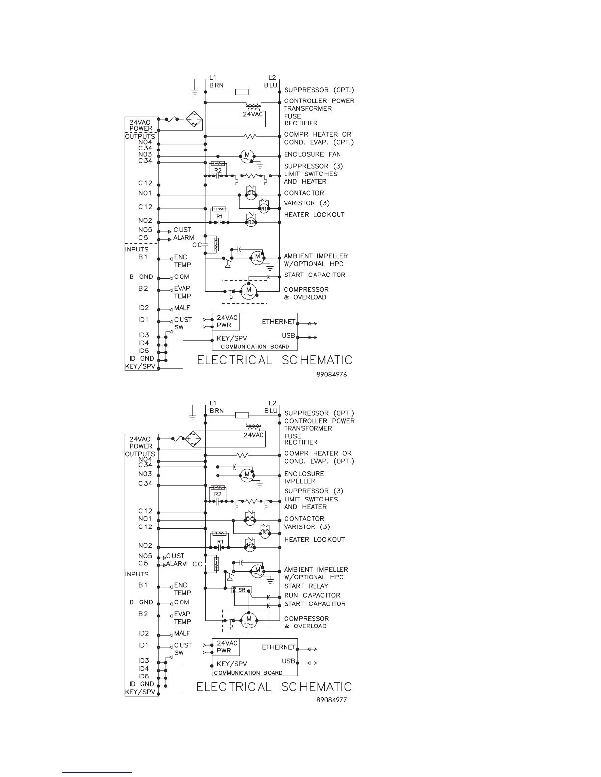
SCHEMATICS AND WIRING DIAGRAMS FOR REMOTE ACCESS CONTROL
Distributed by:
McLean Parts
317-257-6811
5736 N. Michigan Road
Indianapolis, IN 46228
www.mcleanparts.com
4000 BTU 1PHASE SCHEMATIC (ACTUAL UNIT OPTIONS MAY VARY)
6000 BTU 1PHASE SCHEMATIC (ACTUAL UNIT OPTIONS MAY VARY)
89116684
© 2014 Pentair Equipment Protection
- 19 -
Page 20
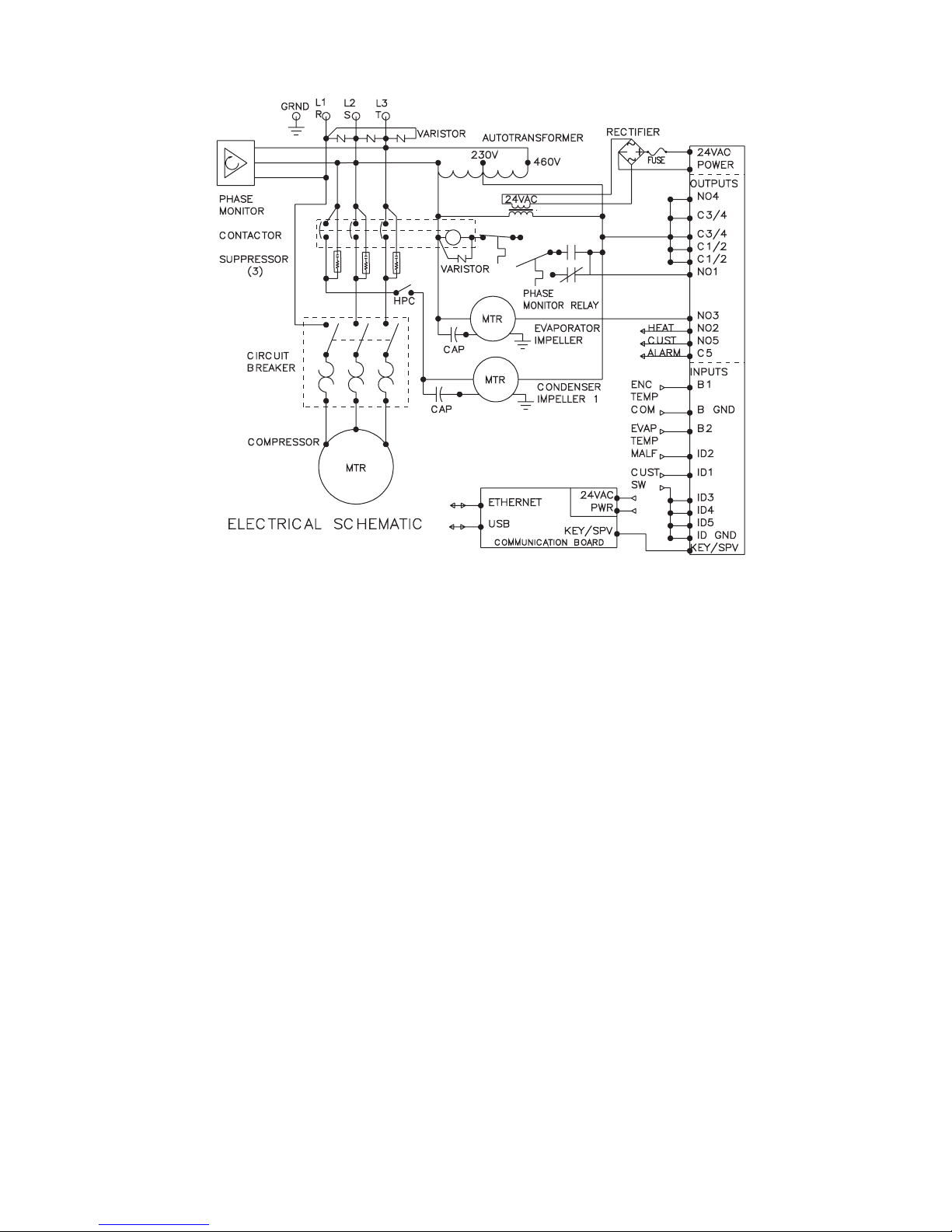
G28 GENERIC 3PHASE SCHEMATIC (ACTUAL UNIT OPTIONS MAY VARY)
Distributed by:
McLean Parts
317-257-6811
5736 N. Michigan Road
Indianapolis, IN 46228
www.mcleanparts.com
- 20 -
© 2014 Pentair Equipment Protection
89116684
Page 21
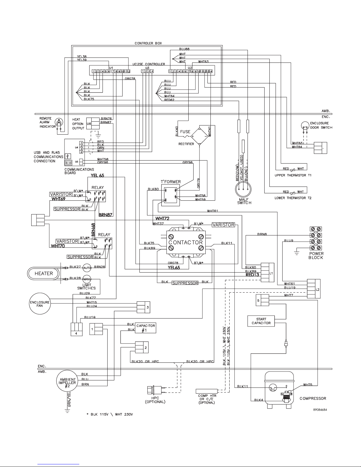
4000 BTU 1PHASE WIRE DIAGRAM FOR REMOTE ACCESS CONTROL (ACTUAL UNIT
Distributed by:
McLean Parts
317-257-6811
5736 N. Michigan Road
Indianapolis, IN 46228
www.mcleanparts.com
OPTIONS MAY VARY)
89116684
© 2014 Pentair Equipment Protection
- 21 -
Page 22
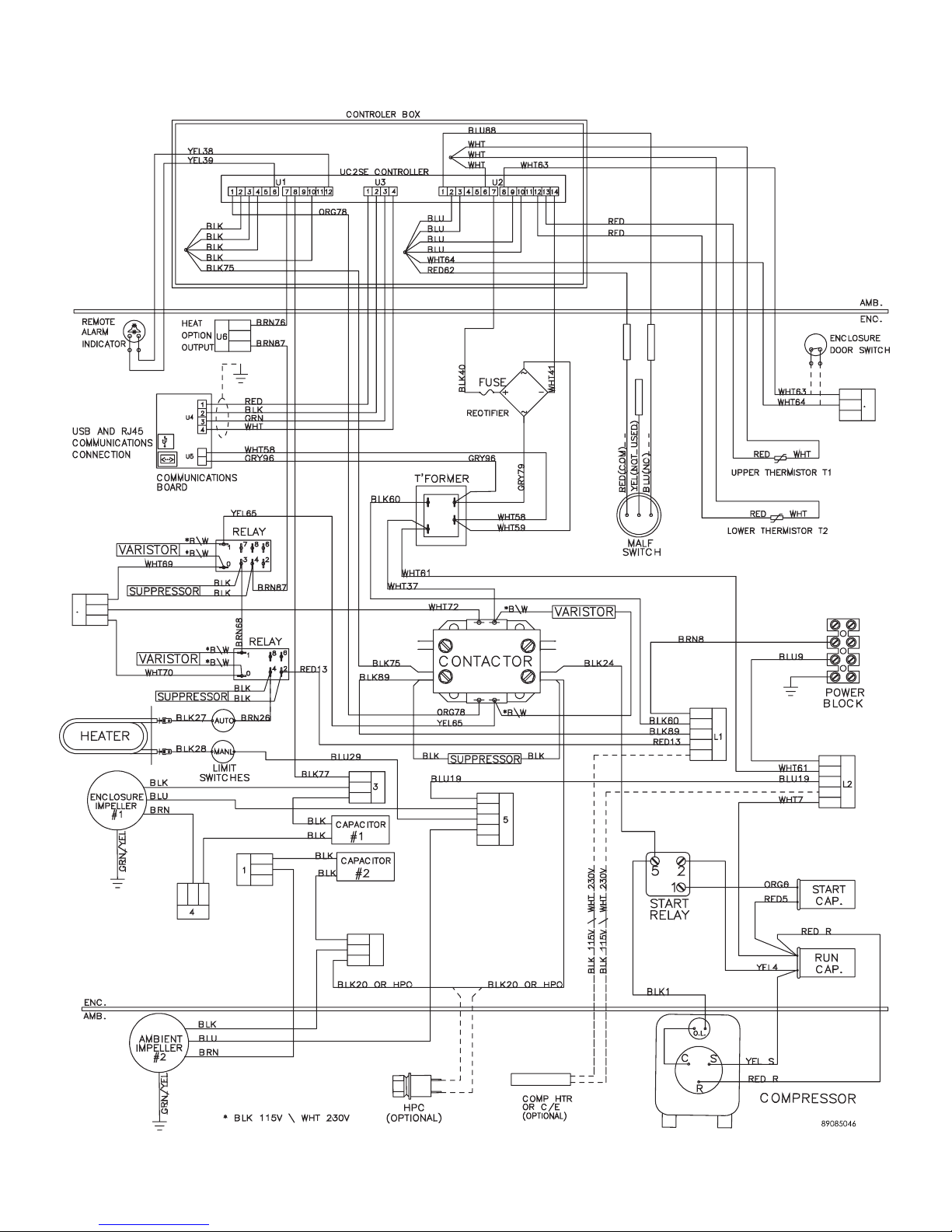
6000 BTU 1PHASE WIRE DIAGRAM FOR REMOTE ACCESS CONTROL (ACTUAL UNIT
Distributed by:
McLean Parts
317-257-6811
5736 N. Michigan Road
Indianapolis, IN 46228
www.mcleanparts.com
OPTIONS MAY VARY)
- 22 -
© 2014 Pentair Equipment Protection
89116684
Page 23
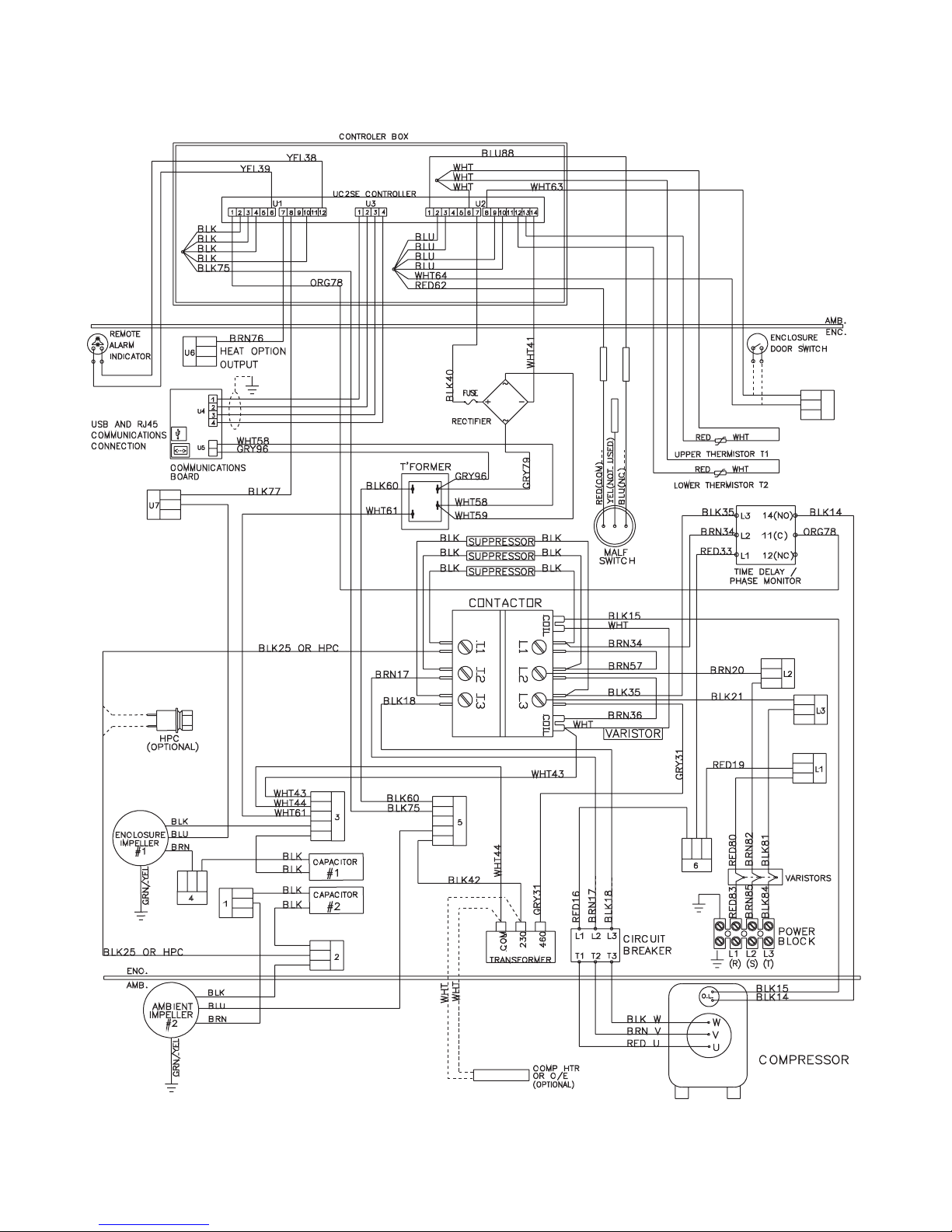
G28 GENERIC 3PHASE WIRE DIAGRAM FOR REMOTE ACCESS CONTROL (ACTUAL UNIT
Distributed by:
McLean Parts
317-257-6811
5736 N. Michigan Road
Indianapolis, IN 46228
www.mcleanparts.com
OPTIONS MAY VARY)
89116684
© 2014 Pentair Equipment Protection
- 23 -
Page 24
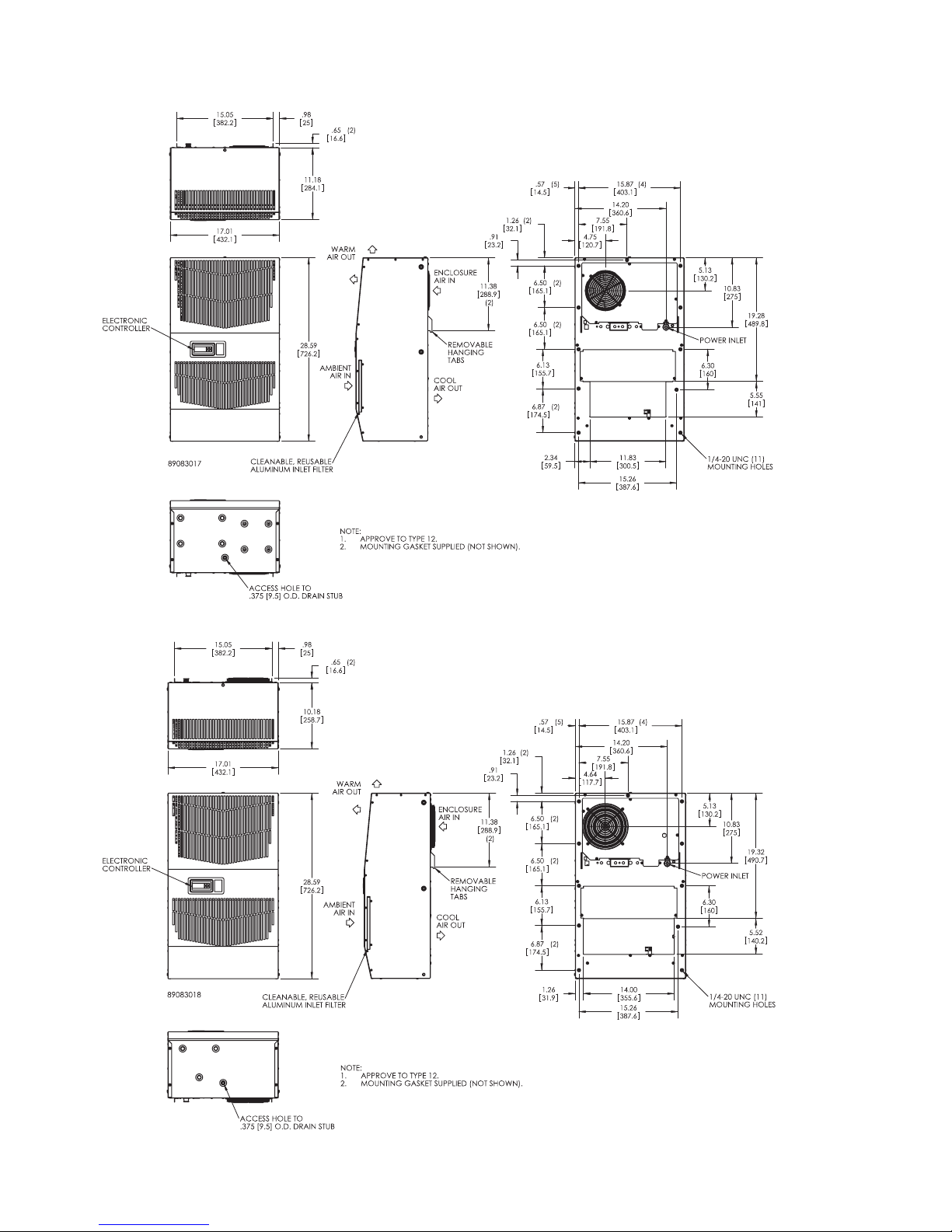
DIMENSIONAL DRAWINGS
Distributed by:
McLean Parts
317-257-6811
5736 N. Michigan Road
Indianapolis, IN 46228
www.mcleanparts.com
4000 BTU 115V WITH REMOTE ACCESS CONTROL
4000 AND 6000 BTU 230V WITH REMOTE ACCESS CONTROL
- 24 -
© 2014 Pentair Equipment Protection
89116684
Page 25
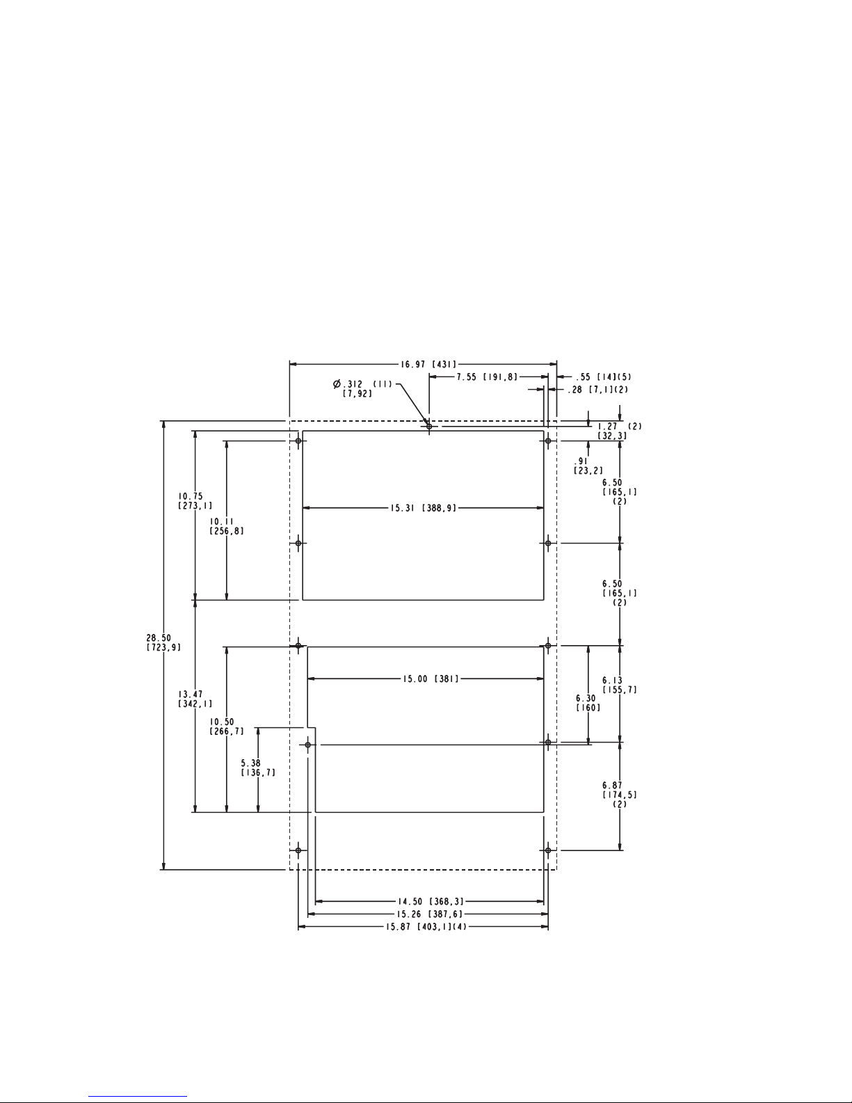
INSTALLATION INSTRUCTIONS WITH REMOTE ACCESS CONTROL
Distributed by:
McLean Parts
317-257-6811
5736 N. Michigan Road
Indianapolis, IN 46228
www.mcleanparts.com
1. Inspect the air conditioner and verify correct functionality before mounting the air conditioner. See
HANDLING AND TESTING THE AIR CONDITIONER on page 3.
2. Using the mounting gasket kit provided with the unit, install gaskets to the air conditioner, see
Figure 2.
3. Mount air conditioner on enclosure taking care not to damage the mounting gasket. The
mounting gasket is the seal between the air conditioner and the enclosure. Avoid dragging the air
conditioner on the enclosure with the mounting gasket attached as this could cause rips or tears
in the gasket and risk losing the water tight seal.
4. Allow unit to remain upright for a minimum of five (5) minutes before starting. CAUTION! Air
conditioner must be in upright position during operation.
5. Refer to the nameplate for electrical requirements. Wire the unit to a properly grounded power
supply. For 3 phase units, once power is applied, verify that phase monitor light is illuminated
which indicates correct electrical phasing. Electrical circuit should be fused with slow blow or
HACR circuit breaker.
6. Set controller setpoints for required cabinet temperature. Refer to DISPLAYING AND CHANGING
PROGRAM VARIABLES on page 14 for setpoint adjustment and operation.
28100013
89116684
Figure 2
Cut-out Drawing
© 2014 Pentair Equipment Protection
- 25 -
Page 26

MAINTENANCE
Distributed by:
McLean Parts
317-257-6811
5736 N. Michigan Road
Indianapolis, IN 46228
www.mcleanparts.com
COMPRESSOR
The compressor requires no maintenance. It is hermetically sealed, properly lubricated at the factory and should
provide years of satisfactory operating service.
Under no circumstances should the access fitting covers be loosened, removed or tampered with.
Breaking of seals on compressor access fittings during warranty period will void warranty on hermetic system.
Recharging ports are provided for the ease and convenience of reputable refrigeration repair service personnel
for recharging the air conditioner.
INLET AIR FILTER
This air conditioner was designed with a dust resistant condenser coil. This allows it to be run filterless in most
applications. The air conditioner is shipped with a filter in place for your convenience. For filterless operation,
simply remove the filter. Should you decide the filter is necessary in your application, regular maintenance to
clean this filter will assure normal operation of the air conditioner. The easily removable inlet air filter is located
behind the front cover. If necessary filter maintenance is delayed or ignored, the maximum ambient temperatures
under which the unit is designed to operate will be decreased.
If the compressor’s operating temperature increases above designed conditions due to a dirty or clogged filter
(or plugged condenser coil), the air conditioner’s compressor will stop operating due to actuation of the thermal
overload cut-out switch located on the compressor housing. As soon as the compressor temperature has dropped
to within the switch’s cut-in setting, the compressor will restart automatically. However the above condition will
continue to take place until the filter or coil has been cleaned. It is recommended that power to the air conditioner
be interrupted intentionally when abnormally high compressor operating temperature causes automatic shutdown of the unit. The above described shut-down is symptomatic of a clogged or dirty filter, thus causing a
reduction in cooling air flow across the surface of the compressor and condenser coil.
HOW TO REMOVE, CLEAN OR INSTALL A NEW INLET AIR FILTER
RP aluminum washable air filters are designed to provide excellent filtering efficiency with a high dust holding
capacity and a minimum amount of resistance to air flow. Because they are constructed entirely of aluminum
they are lightweight and easy to service. To achieve maximum performance from your air handling equipment, air
filters should be cleaned on a regular basis.
The inlet air filter is located behind the front access cover. To remove filter, push or pull to slide filter out from
either side of the unit. The filter may now be cleaned or a new filter installed.
Cleaning Instructions:
1. Flush the filter with warm water from the exhaust side to the intake side. DO NOT USE CAUSTICS.
2. After flushing, allow filter to drain. Placing it with a corner down will assure complete drainage.
- 26 -
© 2014 Pentair Equipment Protection
89116684
Page 27
CONDENSER AND EVAPORATOR AIR MOVERS
Distributed by:
McLean Parts
317-257-6811
5736 N. Michigan Road
Indianapolis, IN 46228
www.mcleanparts.com
Impeller motors require no maintenance. All bearings, shafts, etc. are lubricated during manufacturing for the
life of the motor.
If one of the condenser impeller motors (ambient impellers) should fail, it is not necessary to remove the air
conditioner from the cabinet or enclosure to replace the blower. The condenser blower is mounted on its own
bulkhead and is easily accessible by removing the front cover.
CAUTION
Operation of the air conditioner in areas containing airborne
caustics or chemicals can rapidly deteriorate filters, condenser
coils, blowers and motors, etc. Contact Pentair Equipment
Protection for special recommendations.
REFRIGERANT LOSS
Each air conditioner is thoroughly tested prior to leaving the factory to insure against refrigeration leaks. Shipping
damage or microscopic leaks not found with sensitive electronic refrigerant leak detection equipment during
manufacture may require repair or recharging of the system. This work should only be performed by qualified
professionals, generally available through a local, reputable air conditioning repair or service company.
Should the refrigerant charge be lost, access ports on the suction and discharge sides of the compressor are
provided for recharging and/or checking suction and discharge pressures.
Refer to the data on the nameplate which specifies the type of refrigerant and the charge size in ounces.
Before recharging, make sure there are no leaks and that the system has been properly evacuated into a deep
vacuum.
89116684
© 2014 Pentair Equipment Protection
- 27 -
Page 28

REFRIGERANT PROPERTIES CHART (R 407C)
Distributed by:
McLean Parts
317-257-6811
5736 N. Michigan Road
Indianapolis, IN 46228
www.mcleanparts.com
°F °C
Bubble Point
(PSIG)
Dew Point
(PSIG)
°F °C
Bubble Point
(PSIG)
Dew Point
(PSIG)
-40 -40 2.9 4.5 60 15.6 117.7 96.8
-35 -37.2 5.2 .7 65 18.3 128.7 106.7
-30 -34.4 7.9 1.7 70 21.1 140.2 117.2
-25 -31.7 10.7 4 75 23.9 152.5 128.4
-20 -28.9 13.9 6.5 80 26.7 165.5 140.4
-15 -26.1 17.3 9.3 85 29.4 179.2 153.1
-10 -23.3 21.1 12.4 90 32.2 193.6 166.5
-5 -20.6 25.2 15.8 95 35 208.8 180.8
0 -17.8 29.6 19.5 100 37.8 224.9 195.8
5 -15 34.4 23.6 105 40.6 241.8 211.8
10 -12.2 39.6 28 110 43.3 259.6 228.7
15 -9.4 45.2 32.7 115 46.1 278.2 246.5
20 -6.7 51.3 37.9 120 48.9 297.8 265.3
25 -3.9 57.8 43.6 125 51.7 318.3 285.2
30 -1.1 64.7 49.6 130 54.4 339.9 306.1
35 1.7 72.2 56.2 135 57.2 362.4 328.2
40 4.4 80.2 63.2 140 60 386 351.4
45 7.2 88.7 70.7 145 62.8 410.7 375.9
50 10 97.8 78.8 150 65.6 436.5 401.7
55 12.8 107.5 87.5
REFRIGERANT PROPERTIES CHART (R 134A)
- 28 -
© 2014 Pentair Equipment Protection
89116684
Page 29
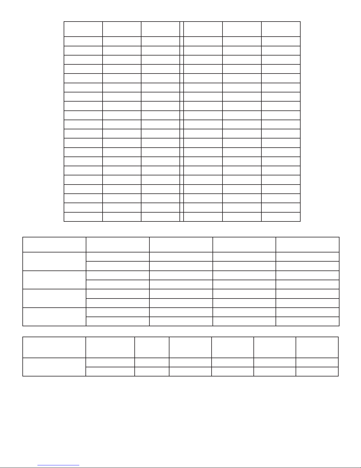
°F °C
Distributed by:
McLean Parts
317-257-6811
5736 N. Michigan Road
Indianapolis, IN 46228
www.mcleanparts.com
Pressure
(PSIG)
°F °C
Pressure
(PSIG)
-40 -40 -14.7 60 15.6 58
-35 -37.2 -12.3 65 18.3 64
-30 -34.4 -9.7 70 21.1 71.5
-25 -31.7 -6.8 75 23.9 78
-20 -28.9 -1 80 26.7 86.7
-15 -26.1 0 85 29.4 95
-10 -23.3 2 90 32.2 105
-5 -20.6 4 95 35 113.3
0 -17.8 7.5 100 37.8 125
5 -15 9 105 40.6 135
10 -12.2 12 110 43.3 146.7
15 -9.4 15 115 46.1 157.5
20 -6.7 18.5 120 48.9 170
25 -3.9 22 125 51.7 185
30 -1.1 26
35 1.7 30
40 4.4 35
45 7.2 40
50 10 45.5
55 12.8 51.5
Unit
G280416GXXX
G280426GXXX
G280616GXXX
G280626GXXX
Unit
G280(4/6)46GXXX
FUNCTIONAL DATA
Evaporator. Air
In(°F)
Amps(A)
65-80 6.1-8.9 16-24 11-23
80-100 6.4-9.4 18-31 11-29
65-80 2.5-3.9 25-33 19-29
80-100 2.9-4.6 27-38 23-33
65-80 5.6-7.4 24-33 24-33
80-100 6.4-9.1 27-38 27-37
65-80 2.5-3.9 25-33 19-29
80-100 2.9-4.6 27-38 23-33
Evaporator. Air
In(°F)
Amps(A)
Evap
Pressure
(PSIG)
65-80 0.8 - 1.5 23 - 43 91 - 161 19 - 29 17 - 27
80-100 1.1 - 1.7 33 - 60 131 - 227 23 - 33 21 - 31
Condenser
Delta(°F)
Cond
Pressure
(PSIG)
Evaporator
Delta(°F)
Condenser
Delta(°F)
Evaporator
Delta(°F)
89116684
© 2014 Pentair Equipment Protection
- 29 -
Page 30
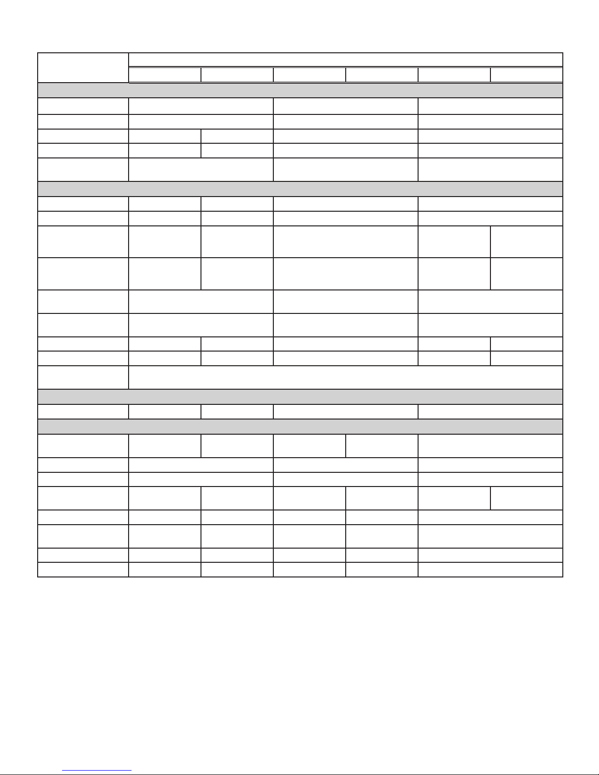
4000/6000 BTU UNIT CHARACTERISTICS
Distributed by:
McLean Parts
317-257-6811
5736 N. Michigan Road
Indianapolis, IN 46228
www.mcleanparts.com
Part Number
G280416GXXX G280426GXXX G280616GXXX G280626GXXX
Dimensional Data
Height 28.55/725.2mm 28.55/725.1 mm 28.55/725.2mm
Width 16.97/431.1mm 16.97/431.1mm 16.97/431.1mm
Depth 11.10/281.9mm 10.10/256.6mm 10.10/256.6mm 10.10/256.6mm
Unit Weight 82 lbs/37 kg 84 lbs/38 kg 84 lbs/38 kg 84 lbs/38 kg
Unit Protection
Rating
Type 12/4/4X/3R Type 12/4/4X/3R Type 12/4/4X/3R
Cooling Data
Refrigerant R134a R407C R407C R134A
Refrigerant Charge 12 oz. 20 oz. 20 oz. 16 oz.
Cooling Capacity at
95 F Enclosure 95 F
3300/3410 4300/4600 5600/6000 4324/4655 5054/5685
Ambient (BTU/Hr./W)
Cooling Capacity at
Max Conditions (BTU/
3700 4600/4900 6000/6400 4600/4900 5400/6000
Hr./W)
Maximum Ambient
Temp
Minimum Ambient
Temp
131 F / 55 C 131 F/55 C 131 F/55 C
-40 F / -40 C -40 F/-40 C -40 F/-40 C
Enclosure Airflow 151/183 CFM 189/221 CFM 189/221 CFM 189/221 CFM 189/221 cfm
External Airflow 284/290 CFM 291/300 CFM 291/300 CFM 291/300 CFM 291/300 cfm
Condensate
Management
Heating Data
Capacity 1000 W 2000 W 2000W N/A
Electrical Data
Rated Voltage (50/60
Hz)
Rated Frequency 50 / 60 Hz 50/60 Hz 50/60 Hz
Voltage Range +/- 10% of rated +/- 10% of rated +/- 10% of rated
Cooling Amps at Max
Conditions
Heating Amps 16.3 9.2 18.2 9.2 N/A
Compressor RLA /
LRA
Evaporator Fan RLA* .31 .48 .82 .48 .48
Condenser Fan RLA* .93 .53 .93 .53 .53
115V 230V 115V 230V 400/460V 3 phase
10.4/10.1 4.6/5.8 9.9/11.4 4.6/5.8 1.7/1.9 1.7/1.9
7.75 / 42 2.6/17.7 5.4/36.2 2.6/17.7 1.7/7.7
G280446GXXX G280646GXXX
- 30 -
© 2014 Pentair Equipment Protection
89116684
Page 31
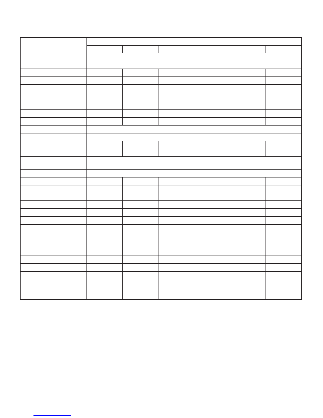
SERVICE DATA
Distributed by:
McLean Parts
317-257-6811
5736 N. Michigan Road
Indianapolis, IN 46228
www.mcleanparts.com
COMPONENTS LIST
Part Description
G280446GXXX G280646GXXX G280416GXXX G280426GXXX G280616GXXX G280626GXXX
Part Number
315 mA Fuse 89085115
Bridge Rectifier 89087424
Capacitor, Compressor, Run N/A N/A N/A S-6173 52-6032-06 S-6173
Capacitor, Compressor, Start N/A N/A 89112001 10-1032-08 10-1032-08 10-1032-08
Capacitor, Condenser
Impeller
Capacitor, Evaporator
Impeller
52-6032-14 52-6032-14 52-6032-13 52-6032-14 52-6032-13 52-6032-14
52-6032-14 52-6032-14 N/A 52-6032-14 52-6032-15 52-6032-14
Coil, Condenser 89051206 89051206 89075089 89051206 89051206 89051206
Coil, Evaporator 28-6010-00 28-6010-00 89075090 28-6010-00 28-6010-00 28-6010-00
Communication Board 89082033
Communication Cable 89080313
Compressor 10-1026-95 10-1026-95 89111751 10-1026-123 10-1016-91 10-1026-123
Contactor Compressor 89098321 89098321 N/A N/A N/A N/A
Controller Wires with pins
(24)
89083091
Controller, Basic 89075653
Filter Air, Reusable 89096883 89096883 89096883 89096883 89096883 89096883
Filter/Dryer 52-6028-00 52-6028-00 52-6028-00 52-6028-00 52-6028-00 52-6028-00
Head Pressure Control Switch 89083016 89083016 89083016 89083015 89083015 89083015
Heater, 2000 Watt N/A N/A 10-1038-55 10-1038-54 10-1038-55 10-1038-54
Impeller Condenser 10-1091-124 10-1091-124 10-1091-123 10-1091-124 10-1091-123 10-1091-124
Impeller Evaporator 10-1091-122 10-1091-122 12-1012-01 10-1091-122 10-1091-121 10-1091-122
Limit Switch (automatic) N/A N/A 10-1033-01 10-1033-01 10-1033-01 10-1033-01
Limit Switch (manual) N/A N/A 10-1033-07 10-1033-07 10-1033-07 10-1033-07
Overload, Compressor 89098323 89098323 N/A N/A N/A N/A
Relay Phase Monitor 89097986 89097986 N/A N/A N/A N/A
Relay, Compressor Start N/A N/A 89115078 10-1042-13 10-1042-06 10-1042-13
Thermal Expansion Valve 10-1040-42 10-1040-42 N/A 89057143 89057143 89057143
Thermal Overload,
Compressor
10-1007-77 10-1007-77 89114723 MRA5742-114 10-1007-18 MRA5742-114
Thermostat SPDT, 55-100F 10-1061-16 10-1061-16 10-1061-16 10-1061-16 10-1061-16 10-1061-16
Transformer 460/230V 800VA 10-1006-128 10-1006-128 N/A N/A N/A N/A
89116684
© 2014 Pentair Equipment Protection
- 31 -
Page 32
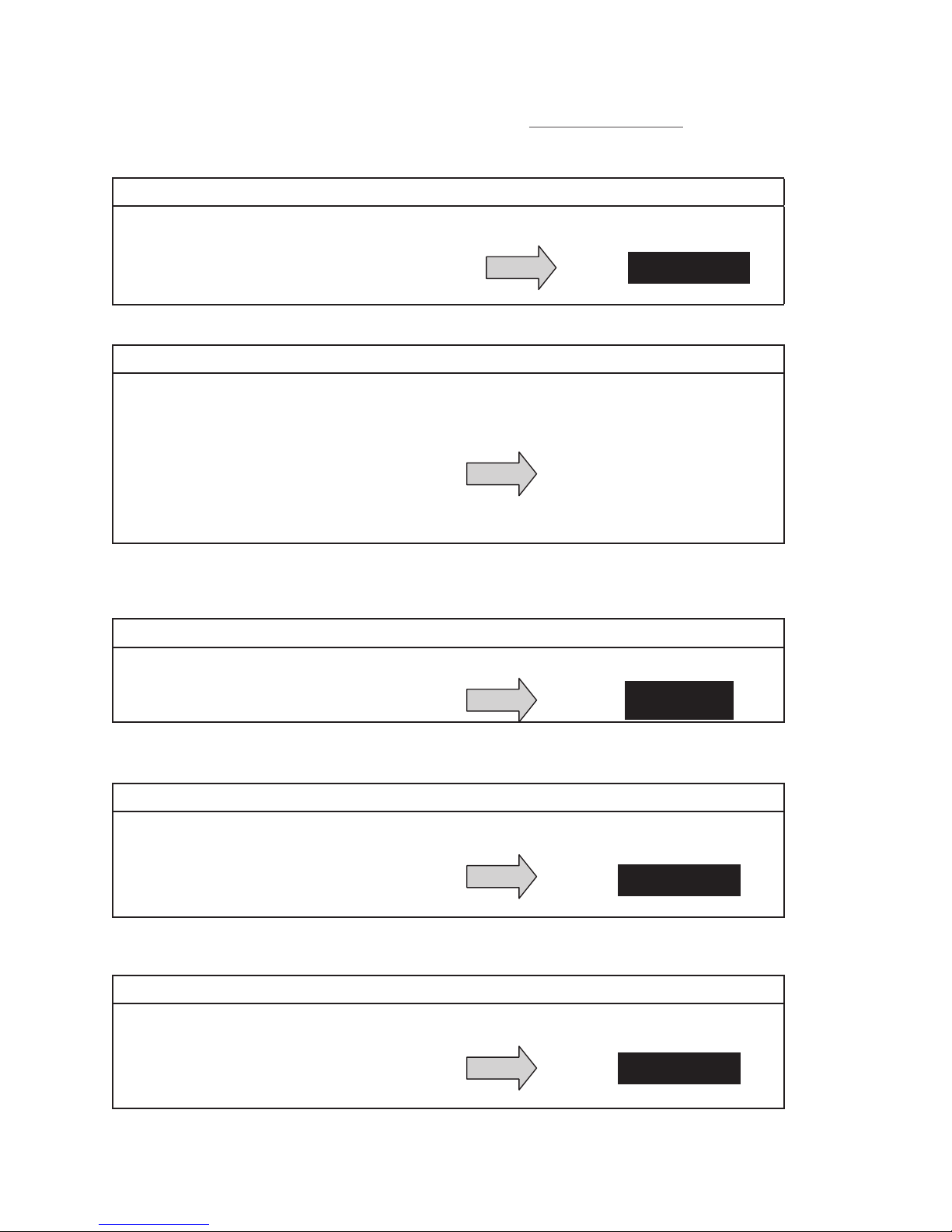
TROUBLE SHOOTING
Repair or Replace
defective part
Repair or Replace
defective part
Repair or Replace
defective part
Distributed by:
McLean Parts
317-257-6811
5736 N. Michigan Road
Indianapolis, IN 46228
www.mcleanparts.com
BASIC AIR CONDITIONING TROUBLE SHOOTING CHECK LIST THERMOSTAT VERSION
1. Check manufacturer’s nameplate located on the unit for correct power supply.
2. Turn on power to the unit. The evaporator (Enclosure or “COLD” air) impeller should come on. Is
there airflow?
YES, proceed to step 3.
NO, possible problem:
» Open motor winding
» Stuck impeller motor
» Obstructed wheel
3. Check phase monitor indicator light, is it Illuminated?
YES, proceed to step 4.
NO, possible problem:
De-energize unit and
swap any two power leads
to unit. If problem still
» Incorrect electrical phasing
persists, replace phase
monitor. Refer to phase
monitor section of this
manual for additional
information.
4. Check thermostat setting and adjust thermostat to the lowest setting. This should turn the
condenser impellers and the compressor on. Did condenser impellers and compressor come on
when the thermostat was turned on?
YES, proceed to step 5.
NO, possible problem:
» Tripped customer door switch
» Defective thermostat
Replace part
5. Are all impellers and the compressor running? If not the unit will not cool properly.
6. Check condenser (Ambient or “HOT” air) impellers for airflow. Is there airflow?
YES, proceed to step 7.
NO, possible problem:
» Defective thermostat
» Open motor winding
» Stuck impeller motor
» Obstructed wheel
7. Carefully check the compressor for operation - motor should cause slight vibration, and the outer
case of the compressor should be warm. Is the compressor showing signs of this?
YES, wait 5 minutes, then proceed to step 8.
NO, possible problem:
» Defective thermostat
» Defective overload
» Defective relay
- 32 -
© 2014 Pentair Equipment Protection
89116684
Page 33
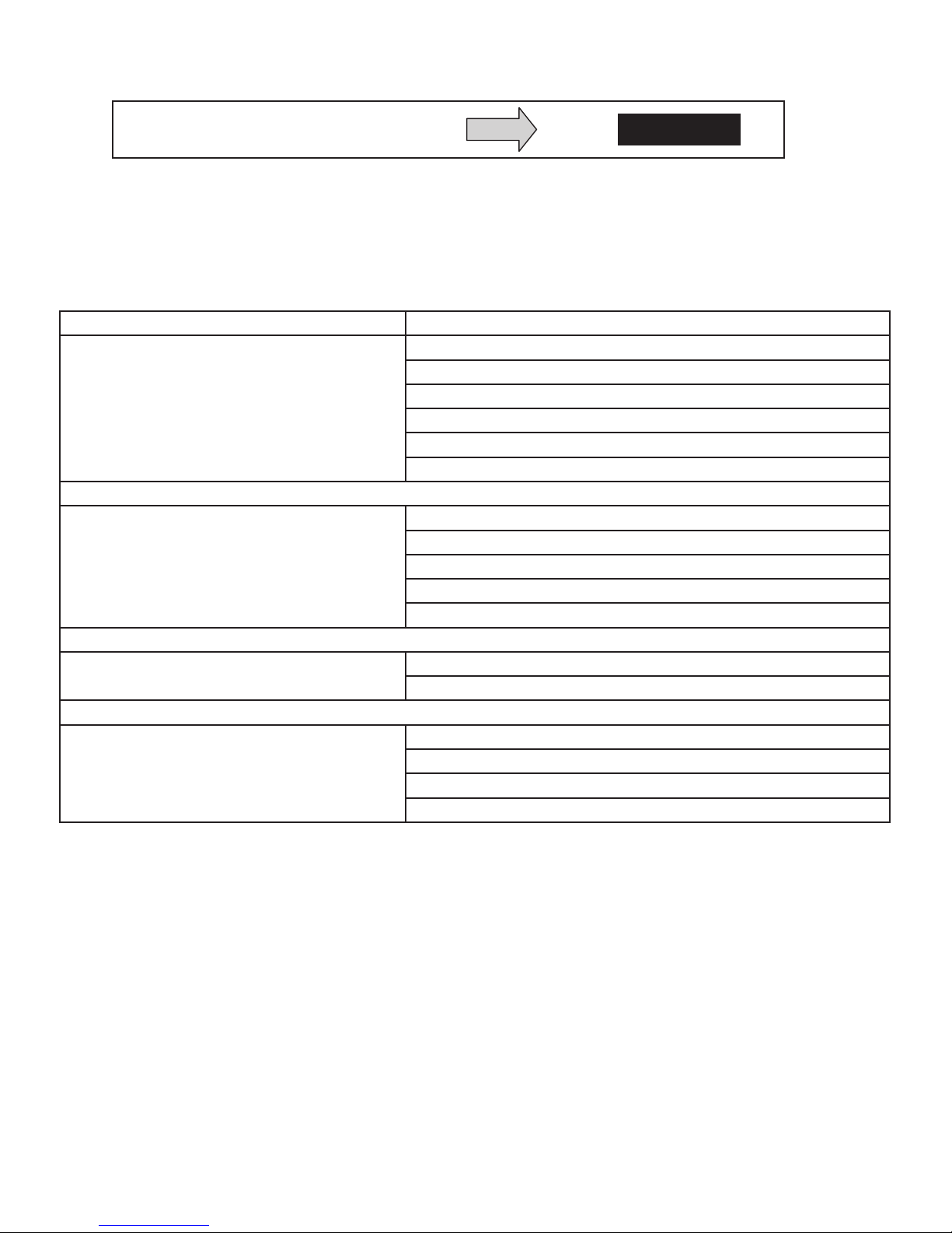
8. Make sure the coils are clean. Then check evaporator “air in” and “air out” temperatures. If the
Repair or Replace
defective part
Distributed by:
McLean Parts
317-257-6811
5736 N. Michigan Road
Indianapolis, IN 46228
www.mcleanparts.com
temperatures are the same:
» Possible loss of refrigerant
» Possible bad valves in the compressor
9. To check for a bad thermostat, turn power to the unit off. Remove the upper access panel and
place both thermostat wires onto one terminal (replace upper access panel for safety). This will
activate the switch in the thermostat. Turn the power on and if all impellers and the compressor
come on, the thermostat needs to be replaced.
SYMPTOMS AND POSSIBLE CAUSES THERMOSTAT VERSION
SYMPTOM POSSIBLE CAUSE
Clogged fins on coil(s)
Dirty filter
Unit won’t cool
Impellers not running
Compressor not running
Compressor runs, but has bad valves
Loss of refrigerant
Low line voltage at start. Should be +/-10% rated voltage.
Compressor motor stuck
Compressor tries to start but won’t run
Bad contactor
Bad overload switch
Bad run/start capacitor
Unit blows breakers
Undersized breaker/fuse or not time delayed
Short in system
Drain plugged
Getting water in enclosure
Drain tube kinked
Enclosure not sealed (allowing humidity in)
Mounting gasket damaged
For additional technical support, contact Pentair Equipment Protection at 800-896-2665.
89116684
© 2014 Pentair Equipment Protection
- 33 -
Page 34
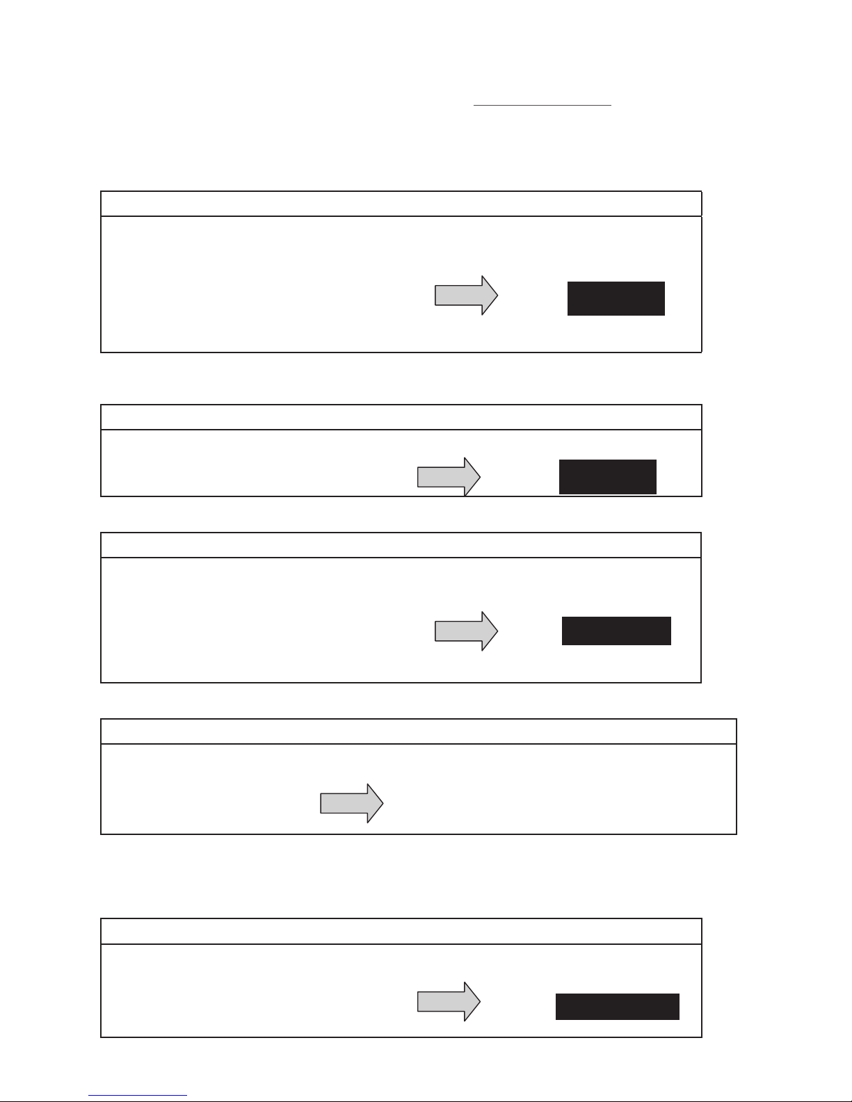
BASIC AIR CONDITIONING TROUBLE SHOOTING CHECK LIST REMOTE ACCESS
Repair or Replace
defective part
Wait and/or heat
enclosure thermistor T1
Distributed by:
McLean Parts
317-257-6811
5736 N. Michigan Road
Indianapolis, IN 46228
www.mcleanparts.com
CONTROL VERSION
1. Check manufacturer’s nameplate located on the unit for correct power supply.
2. Turn on power to the unit. The controller will display a start up sequence then revert to the normal
temperature display mode. Is the correct enclosure temperature displayed?
Note: The temperature may be alternating with an alarm code.
YES, proceed to step 3.
NO, possible problem:
» Open controller fuse
» Controller in alarm condition. See ALARM
CONDITION DISPLAY on page 15.
» Defective controller
» Defective thermistor - check by blowing
warm air across the thermistor. If display
temperature rises, thermistor is operable.
3. The cooling status indication (symbol G) should be on. Is the symbol on? If not, press and hold the
lower right “snowflake” button for greater than five seconds. Is the cooling mode symbol now on?
YES, proceed to step 4.
NO, possible problem:
Replace part
» Defective controller
Replace part
4. The evaporator (Enclosure or “COLD” air) fan/impeller should turn on. Is there airflow?
YES, proceed to step 5.
NO, possible problem:
» Controller in alarm condition. See ALARM
CONDITION DISPLAY on page 15.
» Open motor winding
» Stuck fan/impeller
» Obstructed blades/wheel
» Defective motor capacitor
5. Check phase monitor indicator light, is it Illuminated?
YES, proceed to step 6.
NO, possible problem:
De-energize unit and swap any two power
» Incorrect electrical phasing
leads to unit. If problem still persists, replace
phase monitor. Refer to phase monitor section
of this manual for additional information.
6. Start the cooling cycle by changing the cooling setpoint parameter (r01) to the low limit of 72 F (22
C). Symbol 1 should be displayed indicating a call for cooling. If symbol 1 is flashing, the unit is in
Restart Time Delay mode. Within 6 minutes, symbol 1 should display without flashing. Is symbol 1
displayed without flashing?
YES, proceed to step 7.
NO, possible problem:
» Unit still in Recycle Time Delay mode
» Enclosure temperature below cooling
setpoint temperature
- 34 -
© 2014 Pentair Equipment Protection
89116684
Page 35
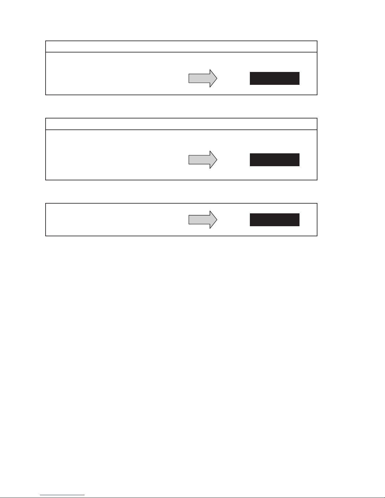
7. The compressor and the condenser (Ambient or “HOT” air) impeller(s) should turn on. Is there
Repair or Replace
defective part
Repair or Replace
defective part
Repair or Replace
defective part
Distributed by:
McLean Parts
317-257-6811
5736 N. Michigan Road
Indianapolis, IN 46228
www.mcleanparts.com
adequate airflow?
YES, proceed to step 8.
NO, possible problem:
» Open motor winding(s)
» Stuck impeller(s)
» Obstructed wheel(s)
» Defective motor capacitor(s)
8. Carefully check the compressor for proper operation - motor should cause slight vibration and the
outer case of the compressor should be warm. Is the compressor showing signs of this?
YES, wait 5 minutes, proceed to step 9.
NO, possible problem:
» Defective start or run capacitor
» Defective overload
» Defective start relay
» Defective contactor
» Defective compressor
9. Make sure the coils are clean then check the evaporator “air in” and “air out” temperatures. If the
temperatures are the same:
» Possible loss of refrigerant
» Possible bad valves in compressor
89116684
© 2014 Pentair Equipment Protection
- 35 -
Page 36

SYMPTOMS AND POSSIBLE CAUSES REMOTE ACCESS CONTROL VERSION
Distributed by:
McLean Parts
317-257-6811
5736 N. Michigan Road
Indianapolis, IN 46228
www.mcleanparts.com
SYMPTOM POSSIBLE CAUSE
Clogged fins on coil(s)
Dirty filter
Unit won’t cool
Compressor tries to start but won’t run
Impellers not running
Compressor not running
Compressor runs, but has bad valves
Loss of refrigerant
Low line voltage at start. Should be +/-10% rated voltage.
Compressor motor stuck
Bad contactor
Bad overload switch
Bad run/start capacitor
Unit blows breakers
Undersized breaker/fuse or not time delayed
Short in system
Drain plugged
Getting water in enclosure
Drain tube kinked
Enclosure not sealed (allowing humidity in)
Mounting gasket damaged
For additional technical support, contact Pentair Equipment Protection at 800-896-2665.
- 36 -
© 2014 Pentair Equipment Protection
89116684
Page 37

NOTES
Distributed by:
McLean Parts
317-257-6811
5736 N. Michigan Road
Indianapolis, IN 46228
www.mcleanparts.com
89116684
© 2014 Pentair Equipment Protection
- 37 -
Page 38

WARRANTY
Distributed by:
McLean Parts
317-257-6811
5736 N. Michigan Road
Indianapolis, IN 46228
www.mcleanparts.com
Pentair Equipment Protection warrants that the Goods manufactured by Pentair Equipment Protection
will be free from defects in material and workmanship for a period of one (1) year from the date of
shipment by Pentair Equipment Protection, subject to the following conditions and exclusions:
A. Conditions. All Goods must be installed and operated according to the following specifications:
1. Maximum voltage variation no greater than plus or minus 10% of nameplate nominal rating;
2. Maximum frequency variation no greater than plus or minus 3 Hz of nameplate nominal rating;
3. Must not exceed minimum and maximum stated temperatures on the nameplate;
4. Must not exceed (BTU/Hr) rating, including any heat sink as indicated on the nameplate;
5. Refrigerant bearing Goods must not be restarted for a period of one (1) minute after intentional or
accidental shut-off;
6. The filters (if applicable) must be cleaned regularly;
7. The Goods and any parts thereof must not be modified, unless prior written authorization is
received from Pentair Equipment Protection; and
8. All Goods must be installed and grounded in accordance with all relevant electrical and safety
codes, as well as the National Electric Code and OSHA rules and regulations.
9. All Goods must be installed in a stationery application, free of vibration.
A violation of any one of these conditions shall render the warranty hereunder void and of no effect.
B. Exclusions. This warranty shall be void if product is misapplied in any way or:
1. Buyer specified product is inappropriate for system or environment in which it is operating.
2. Goods are not installed in accordance with Pentair Equipment Protection specifications.
3. Removal or modification of Pentair Equipment Protection label affixed to product without written
Pentair Equipment Protection approval.
Pentair Equipment Protection must be notified of a claim in writing not later than fourteen (14) days from
the date when Buyer has become aware of such occurrence, or where the defect is such that it may cause
damage, immediately, such notice containing a description of how the defect manifests itself. Failure to
provide such prompt notice to Pentair Equipment Protection shall result in forfeiture of Buyer’s rights
under this warranty.
In the event of a warranty claim, Buyer is to return defective goods to Pentair Equipment Protection in
accordance with Pentair Equipment Protection Return Policy. Warranty period for repaired goods remains
at 1 year from shipment of original goods. Pentair Equipment Protection sole obligation to Buyer under
this warranty will be, at Pentair Equipment Protection option:
A. Repair or replace Pentair Equipment Protection products or parts found to be defective in material or
workmanship.
B. Issue credit for the purchase price paid by Buyer relating to such defective Goods or part.
THIS WARRANTY CONSTITUTES THE ENTIRE WARRANTY WITH RESPECT TO THE GOODS AND IS IN
LIEU OF ALL OTHER WARRANTIES, EXPRESSED OR IMPLIED, INCLUDING ANY IMPLIED WARRANTY OF
MERCHANTABILITY AND IMPLIED WARRANTY OF FITNESS FOR A PARTICULAR PURPOSE.
RETURN AND REPAIR POLICY
Pentair Equipment Protection products that: (i) are made to order, (ii) have been modified by Buyer, (ii)
have special finishes, or (iv) are determined by Pentair Equipment Protection to constitute “custom”
products that cannot be returned to stock or resold to other Buyers, will not be accepted for return by
Pentair Equipment Protection.
All returns require a Return Material Authorization number (RMA #), regardless of reason for return,
whether it be for warranty or out of warranty repair. Returns without an RMA # will be refused by our
Receiving Department. An RMA # is valid for 30 days.
- 38 -
© 2014 Pentair Equipment Protection
89116684
Page 39

A. An RMA # will be issued by our Product Return Department in Anoka, MN at 763-422-2211. Buyer
Distributed by:
McLean Parts
317-257-6811
5736 N. Michigan Road
Indianapolis, IN 46228
www.mcleanparts.com
should have following information available at time of RMA request:
1. Complete Model Number, Serial Number and description of damaged unit being returned.
2. Original Buyer Purchase Order number and date product was received by Buyer.
3. Quantity to be returned and a brief description of failure for each unit, if different.
4. Contact information of Buyer that must include: name of company, billing and shipping address,
phone, number, fax number, freight carrier and the name and phone number of a Buyer contact
who can elaborate on the claimed defect in detail.
5. Buyer must provide a Repair Purchase Order number for both warranty and out of warranty
repairs. The PO will not exceed 50% of a new unit. Buyer will be notified of repair charges that
exceed approved PO amount.
B. All returns to Pentair Equipment Protection must be securely packed, using original cartons if
possible. All returns must have the RMA number visible on the outside of the carton. Pentair
Equipment Protection is not responsible for material damaged in transit. Any refrigerant-bearing
Goods must be shipped upright for return.
C. Shipping cost for all non-warranty repairs is the responsibility of the sender and must be shipped
prepaid. Shipping costs for all warranty related repairs will be covered by Pentair Equipment
Protection provided the goods are returned using a Pentair Equipment Protection approved carrier.
If after diagnoses the product is determined by Pentair Equipment Protection not be covered under
warranty, Buyer will be responsible for all shipping charges and will be billed accordingly.
D. Non-warranty repairs are subject to a $105 minimum analysis fee. If approval is not received within
30 days, material will be scrapped and all shipping expenses and corresponding analysis fees will be
billed to Buyer.
E. At Buyer’s request, Failure Analysis can be provided by Pentair Equipment Protection for warrantable
goods at no charge. Failure analysis for non-warranty repairs are subject to a $150 per hour
Engineering charge plus any other incurred testing costs.
F. All returned merchandise must be sent to the following address: Pentair Equipment Protection, 2100
Hoffman Way, Anoka, MN 55303-1745.
G. Credit for accepted returns shall be at the original selling price or the current selling price, whichever
is lower, less the restocking charge indicated as follows:
1. Within 60 days of invoice date - 20% of applicable selling price.
2. Within 61-120 days of invoice date - 30% of applicable selling price.
3. Within 121-180 days of invoice date - 40% of applicable selling price.
4. Beyond 180 days - subject to individual review by Pentair Equipment Protection.
If product being returned for credit requires repair or modification, the cost of any labor or material
necessary to bring product into saleable condition will be deducted from credit. Buyer may not take credit
against returns without prior written Pentair Equipment Protection approval.
LIMITATION OF LIABILITY
PENTAIR EQUIPMENT PROTECTION WILL NOT BE LIABLE UNDER ANY CIRCUMSTANCES FOR ANY
INCIDENTAL, CONSEQUENTIAL OR SPECIAL DAMAGES, INCLUDING WITHOUT LIMITATION ANY LOST
PROFITS OR LABOR COSTS, ARISING FROM THE SALE, USE OR INSTALLATION OF THE GOODS, FROM
THE GOODS BEING INCORPORATED INTO OR BECOMING A COMPONENT OF ANOTHER PRODUCT,
FROM ANY BREACH OF THIS AGREEMENT OR FROM ANY OTHER CAUSE WHATSOEVER, WHETHER
BASED ON WARRANTY (EXPRESSED OR IMPLIED) OR OTHERWISE BASED ON CONTRACT, OR ON TORT
OR OTHER THEORY OF LIABILITY, AND REGARDLESS OF ANY ADVICE OR REPRESENTATIONS THAT
MAY HAVE BEEN RENDERED BY PENTAIR EQUIPMENT PROTECTION CONCERNING THE SALE, USE OR
INSTALLATION OF THE GOODS.
89116684
© 2014 Pentair Equipment Protection
- 39 -
Page 40

Pentair Equipment Protection
2100 Homan
Way
M
Pe
Distributed by:
McLean Parts
317-257-6811
5736 N. Michigan Road
Indianapolis, IN 46228
www.mcleanparts.com
inneapolis, MN 55303 USA
+1.763.422.2211
+1.763.576.3200
ntairProtect.com
Rev. A
© 2014 Pentair Equipment Protection 89116684
P/N 89116684
 Loading...