

Page 1

VersaSync
®
User Manual
Document Part No.: 1228-5000-0050
Revision: 6.0
Date: 20-August-2018
spectracom.com
Page 2

Page 3

© 2018 Spectracom. All rights reserved.
The information in this document has been carefully reviewed and is
believed to be accurate and up-to-date. Spectracom assumes no responsibility for any errors or omissions that may be contained in this document,
and makes no commitment to keep current the information in this manual, or
to notify any person or organization of updates. This User Manual is subject to change without notice. For the most current version of this documentation, please see our web site at spectracom.com.
Spectracom reserves the right to make changes to the product described in
this document at any time and without notice. Any software that may be
provided with the product described in this document is furnished under a
license agreement or nondisclosure agreement. The software may be used
or copied only in accordance with the terms of those agreements.
No part of this publication may be reproduced, stored in a retrieval system, or transmitted in any form or any means electronic or mechanical,
including photocopying and recording for any purpose other than the purchaser's personal use without the written permission of Spectracom.
Other products and companies referred to herein are trademarks or
registered trademarks of their respective companies or mark holders.
Orolia USA, Inc. dba Spectracom
• 1565 Jefferson Road, Suite 460,Rochester, NY 14623 USA
• Room 208,No. 3 Zhong Guan Village South Road, Hai Dian District, Beijing 100081, China
Do you have questions or comments regarding this User Manual ?
è E-mail:
For a copy of Spectracom's Limited Warranty policy, see the Spectracom
website: http://spectracom.com/support/warranty-information.
• 3, Av enue du Canada, 91974 Les UlisCedex, France
Warranty Information
VersaSync User Manual I
Page 4

Blank page.
II VersaSync User Manual
Page 5

CHAPTER 1
Product Description
1.1 Getting Started
1.2 VersaSync Overview
1.3 Status LEDs
1.3.1 Blinking Intervals
1.3.2 LED Lighting Patterns
1.3.3 Legend, individual LEDs
1.3.3.1 LED Patterns during Boot Sequence
1.3.4 Blackout Mode
1.4 Interfaces Overview
1.4.1 Input Timing Interfaces
1.4.2 Output Timing Interfaces
1.4.3 Other Interfaces
1.5 Connectors and their Pinouts
1.5.1 Power Connector
1.5.2 Input/Output Connector
1.5.3 Ethernet Connector
1.5.4 Optional I/O Connector
1.5.5 Coaxial Connectors
1.5.5.1 ODU® ordering contact information (USA):
1
2
2
3
4
4
5
6
6
6
7
7
7
8
8
8
10
10
10
11
CONTENTS
1.6 Included Cables
1.7 VersaSync Specifications
1.7.1 Supply Power
1.7.2 GNSS Receiver
1.7.3 Mechanical & Environmental Specifications
1.7.3.1 Physical Specifications
1.7.3.2 Environmental Requirements
1.8 The VersaSync Web UI
1.8.1 The Web UI HOME Screen
1.8.2 The INTERFACES Menu
VersaSync User Manual • TABLE OF CONTENTS
12
14
14
14
15
15
15
16
16
17
III
Page 6

1.8.3 The Configuration MANAGEMENT Menu
1.8.4 The TOOLS Menu
SAFETY
18
19
20
1.9 SAFETY: Before You Begin Installation
1.10 SAFETY: User Responsibilities
1.11 SAFETY: Other Tips
CHAPTER 2
SETUP
2.1 Installation Overview
2.1.1 Hardware Connections
2.1.2 Mounting
2.1.2.1 Selecting a Mounting Location
2.1.2.2 Heat Dissipation
2.1.2.3 Fasteners
2.1.2.4 Grounding
2.2 Initial Network Setup
2.2.1 USB Driver
2.2.2 Network Address
2.3 Zero Configuration Setup
2.3.1 Using Zeroconf
20
21
22
23
24
24
25
25
26
26
27
27
27
28
30
31
IV
2.4 Accessing the WebUI
2.5 Setting up an IP Address
2.5.1 Assigning a Static IP Address
2.5.2 Subnet Mask Values
2.6 Configuring Inputs/Outputs
2.6.1 Assigning I/O Pins
2.6.1.1 Signal Types
2.6.1.2 I/O Signal Mapping Table
2.6.2 Configuring I/O Settings
2.6.2.1 How to Configure an Input Reference
2.6.2.2 How to Configure an Output
2.6.3 Example: Configuring a 20 PPS Output
2.6.4 Configurable I/Os
2.6.4.1 Configuring a 1PPS Input
31
32
33
34
35
36
37
37
40
40
41
41
43
43
VersaSync User Manual • TABLE OF CONTENTS
Page 7

2.6.4.2 Configuring a 1PPS Output
2.6.4.3 Configuring an ASCII Input
2.6.4.4 Configuring an ASCII Output
2.6.4.5 Configuring a HaveQuick Input
2.6.4.6 Configuring a HaveQuick Output
2.6.5 Signature Control
44
45
47
50
51
52
2.7 Configuring Network Settings
2.7.1 General Network Settings
2.7.2 Network Ports
2.7.3 Network Services
2.7.4 Access Rules
2.7.5 SSH
2.7.6 SNMP
2.7.6.1 SNMP V1/V2c
2.7.6.2 SNMP V3
2.7.6.3 SNMP Traps
2.7.7 System Time Message
2.7.7.1 System Time Message Format
2.7.8 Configuring NTP
2.7.8.1 Checklist NTP Configuration
2.7.8.2 The NTP Setup Screen
2.7.8.3 Dis-/Enabling NTP
2.7.8.4 Viewing NTP Clients
2.7.8.5 Restoring the Default NTP Configuration
2.7.8.6 NTP Output Timescale
2.7.8.7 NTP Reference Configuration
2.7.8.8 NTP Servers and Peers
2.7.8.9 NTP Authentication
2.7.8.10 NTP Access Restrictions
2.7.8.11 NTP Expert Mode
2.7.8.12 Spectracom Technical Support for NTP
2.7.9 Configuring PTP
2.7.9.1 The PTP Screen
2.7.9.2 Enabling/Disabling PTP
2.7.9.3 Configuration — General Steps
2.7.10 GPSD Setup
54
55
55
57
58
59
66
70
71
73
75
76
77
77
78
80
81
82
82
84
86
93
101
102
105
106
106
109
110
110
VersaSync User Manual • TABLE OF CONTENTS
V
Page 8

CHAPTER 3
Managing Time
3.1 The Time Management Screen
3.2 System Time
3.2.1 System Time
3.2.1.1 Configuring the System Time
3.2.1.2 Timescales
3.2.1.3 Manually Setting the Time
3.2.1.4 Using Battery Backed Time on Startup
3.2.2 Timescale Offset(s)
3.2.2.1 Configuring a Timescale Offset
3.2.3 Leap Seconds
3.2.3.1 Reasons for a Leap Second Correction
3.2.3.2 Leap Second Alert Notification
3.2.3.3 Leap Second Correction Sequence
3.2.3.4 Configuring a Leap Second
3.2.4 Local Clock(s), DST
3.2.4.1 Adding a Local Clock
3.2.4.2 DST Examples
3.2.4.3 DST and UTC, GMT
113
114
115
116
116
117
118
120
122
122
123
123
124
124
125
126
126
128
129
3.3 Managing References
3.3.1 Input Reference Priorities
3.3.1.1 Configuring Input Reference Priorities
3.3.1.2 The "Local System" Reference
3.3.1.3 The "User/User" Reference
3.3.1.4 Reference Priorities: EXAMPLES
3.3.2 Reference Qualification and Validation
3.3.2.1 BroadShield
3.3.3 The GNSS Reference
3.3.3.1 Reviewing the GNSS Reference Status
3.3.3.2 Determining Your GNSS Receiver Model
3.3.3.3 Selecting a GNSS Receiver Mode
3.3.3.4 Setting GNSS Receiver Dynamics
3.3.3.5 Performing a GNSS Receiver Survey
3.3.3.6 GNSS Receiver Offset
3.3.3.7 Resetting the GNSS Receiver
3.3.3.8 Deleting the GNSS Receiver Position
3.3.3.9 Manually Setting the GNSS Position
129
129
131
133
134
136
139
139
147
148
152
153
155
157
159
160
161
162
VI
VersaSync User Manual • TABLE OF CONTENTS
Page 9

3.3.3.10 GNSS Constellations
3.3.4 Holdover Mode
164
167
3.4 Managing the Oscillator
3.4.1 Configuring the Oscillator
3.4.1.1 Time Figure of Merit (TFOM)
3.4.2 Monitoring the Oscillator
3.4.3 Oscillator Logs
CHAPTER 4
System Administration
4.1 Issuing the HALT Command Before Removing Power
4.2 Rebooting the System
4.3 Notifications
4.3.1 Configuring Notifications
4.3.2 Notification Event Types
4.3.2.1 Timing Tab: Events
4.3.2.2 GPS Tab: Events
4.3.2.3 System Tab: Events
4.3.3 Configuring GPS Notification Alarm Thresholds
4.3.4 Setting Up SNMP Notifications
4.3.5 Setting Up Email Notifications
171
172
174
175
178
179
180
181
181
182
184
184
184
185
185
186
187
4.4 Managing Users and Security
4.4.1 Managing User Accounts
4.4.1.1 Types of Accounts
4.4.1.2 About "user" Account Permissions
4.4.1.3 Rules for Usernames
4.4.1.4 Adding/Deleting/Changing User Accounts
4.4.2 Managing Passwords
4.4.2.1 Configuring Password Policies
4.4.2.2 The Administrator Password
4.4.2.3 Lost Password
4.4.3 Web UI Timeout
4.5 Miscellanous Typical Configuration Tasks
4.5.1 Creating a Login Banner
4.5.2 Show Clock
189
189
189
189
191
191
193
194
194
195
197
197
197
199
VersaSync User Manual • TABLE OF CONTENTS
VII
Page 10

4.5.3 Synchronizing Network PCs
200
4.6 Quality Management
4.6.1 System Monitoring
4.6.1.1 Status Monitoring via the Web UI
4.6.1.2 Ethernet Monitoring
4.6.1.3 Monitoring the Oscillator
4.6.1.4 NTP Status Monitoring
4.6.2 Logs
4.6.2.1 Types of Logs
4.6.2.2 The Logs Screen
4.6.2.3 Displaying Individual Logs
4.6.2.4 Saving and Downloading Logs
4.6.2.5 Setting up a Remote Log Server
4.6.2.6 Clearing All Logs
4.7 Updates and Licenses
4.7.1 Software Updates
4.7.2 Applying a License File
4.8 Resetting the Unit to Factory Configuration
4.8.1 Resetting All Configurations to their Factory Defaults
4.8.2 Backing-up and Restoring Configuration Files
4.8.2.1 Accessing the System Configuration Screen
4.8.2.2 Saving the System Configuration Files
4.8.2.3 Uploading Configuration Files
4.8.2.4 Restoring the System Configuration
4.8.2.5 Restoring the Factory Defaults
4.8.3 Cleaning the Configuration Files and Halting the System
4.8.4 Default and Recommended Configurations
200
200
200
203
204
207
212
212
216
217
218
219
220
221
221
222
223
224
224
225
227
227
228
229
229
230
VIII
APPENDIX
Appendix
5.1 Troubleshooting
5.1.1 Minor and Major Alarms
5.1.2 Troubleshooting: System Configuration
5.1.2.1 System Troubleshooting: Browser Support
5.1.3 Troubleshooting – Unable to Open Web UI
5.1.4 Troubleshooting via Web UI Status Page
5.1.5 Troubleshooting GNSS Reception
233
234
234
234
235
235
236
237
VersaSync User Manual • TABLE OF CONTENTS
Page 11

5.1.6 Troubleshooting – 1PPS, 10 MHz Outputs
5.1.7 Troubleshooting – Network PCs Cannot Sync
5.1.8 Troubleshooting Software Update
238
239
239
5.2 Command-Line Interface
5.2.1 Setting up a Terminal Emulator
5.2.2 CLICommands
5.3 Time Code Data Formats
5.3.1 NMEAGGA Message
5.3.2 NMEARMC Message
5.3.3 NMEAZDA Message
5.3.4 Spectracom Format 0
5.3.5 Spectracom Format 1
5.3.6 Spectracom Format 1S
5.3.7 Spectracom Format 2
5.3.8 Spectracom Format 3
5.3.9 Spectracom Format 4
5.3.10 Spectracom Format 7
5.3.11 Spectracom Format 8
5.3.12 Spectracom Format 9
5.3.12.1 Format 9S
5.3.13 Spectracom Epsilon Formats
5.3.13.1 Spectracom Epsilon TOD1
5.3.13.2 Spectracom Epsilon TOD3
5.3.14 BBC Message Formats
5.3.14.1 Format BBC-01
5.3.14.2 Format BBC-02
5.3.14.3 Format BBC-03 PSTN
5.3.14.4 Format BBC-04
5.3.14.5 Format BBC-05 (NMEA RMC Message)
5.3.15 GSSIP Message Format
5.3.16 EndRun Formats
5.3.16.1 EndRun Time Format
5.3.16.2 EndRunX (Extended) Time Format
5.3.17 Event Broadcast Time Code Formats
5.3.17.1 Event Broadcast Format 0
5.3.17.2 Event Broadcast Format 1
240
240
241
246
246
247
248
248
249
251
252
255
256
258
259
260
261
262
262
262
263
263
264
265
267
268
268
269
269
270
271
271
272
VersaSync User Manual • TABLE OF CONTENTS
IX
Page 12

5.4 IRIG Standards and Specifications
5.4.1 About the IRIG Output Resolution
5.4.2 IRIG Carrier Frequencies
5.4.3 IRIG B Output
5.4.4 IRIG E Output
5.4.5 IRIG Output Accuracy Specifications
273
273
273
277
280
284
5.5 Product Registration
5.6 Technical Support
5.7 Return Shipments
5.8 License Notices
5.9 List of Tables
5.10 List of Images
5.11 Document Revision History
INDEX
5.6.1 Regional Contact
5.8.1 NTPv4.2.6p5
5.8.2 OpenSSH
5.8.3 OpenSSL
285
286
286
287
287
287
291
294
298
299
299
X
VersaSync User Manual • TABLE OF CONTENTS
Page 13

Product Description
The Chapter presents an overview of the VersaSync Time and Frequency Synchronization System, its capabilities, main technical features and specifications.
The following topics are included in this Chapter:
1.1 Getting Started 2
1.2 VersaSync Overview 2
1.3 Status LEDs 3
1.4 Interfaces Overview 6
1.5 Connectors and their Pinouts 8
1.6 Included Cables 12
1.7 VersaSync Specifications 14
1.8 The VersaSync Web UI 16
CHAPTER 1
CHAPTER 1 • VersaSync User Manual
1
Page 14
1.1 Getting Started
1.1 Getting Started
Welcome to the VersaSync User Manual .
First steps:
If you are not yet familiar with VersaSync, you may want to start here: "VersaSync Overview" below.
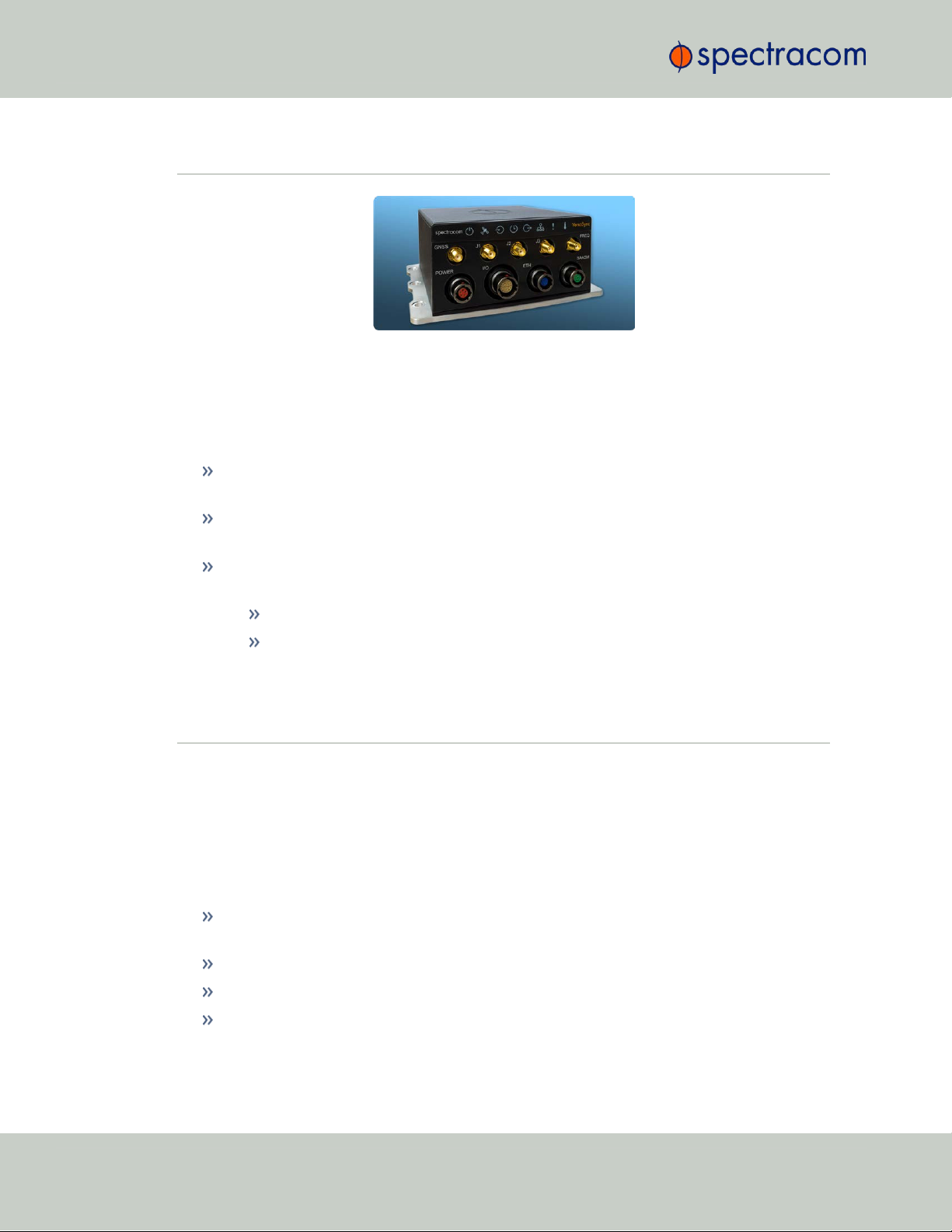
Figure 1-1: VersaSync Rugged GPS Time & Frequency Reference
If you are ready to begin the installation process, see: "Initial Network Setup" on
page27
If your unit is already up and running, and you would like to change specific settings,
see …
… "Managing Time" on page113, or
… "System Administration" on page179.
1.2 VersaSync Overview
VersaSync is a high-performance time & frequency GPS master clock and network time server
that delivers accurate, software configurable time and frequency signals under all circumstances, including GNSS-denied environments. Its compact size and high level of ruggedization make VersaSync suitable for mobile applications in harsh environments.
VersaSync's small footprint allows for easy integration of the time and frequency functionality
into systems architecture.
VersaSync includes all the timing functionality required in modern, network-centric applications:
NTP/PTP precise time transfer over Ethernet, including security protocols that prevent network vulnerabilities
Low phase noise 10 MHz frequency distribution
Configurable pulse signals, including IRIG or HaveQuick timecodes
Serial link Time Of Day (ToD) messages
2
CHAPTER 1 • VersaSync User Manual Rev. 6.0
Page 15

1.3 Status LEDs
GPS-Denied Environments
VersaSync accommodates an OCXO oscillator, allowing the unit to maintain frequency and
time accuracy for long periods of GPS/GNSS outage. In addition, it can be re-synchronized
by an external reference.
Reliable, Versatile, and Configurable
VersaSync physical inputs and outputs are software configurable and can adapt to various
application requirements. I/O pins can be configured as TTL, 10 V pulse, RS232, RS422, and
RS485. This allows VersaSync to provide a high number of outputs of the same type, while still
fitting into a small form factor. However, if the combination of software configurable outputs is
not enough, VersaSync can accommodate an option board (within the same form factor),
designed to customer requirements to provide additional outputs of the same type or other type
of interface (IRIG AM, etc…).
Due to its high level of ruggedization, VersaSync provides very high intrinsic reliability. Strong
status monitoring capability, either locally or remotely, allows quick fault diagnosis. Physical
alarm (dry contact) and network alarms (SNMP traps) are raised in real time. An internal,
exportable log can be accessed either locally or remotely. In addition to oscillator options
(OCXO), VersaSync is available with a C/A L1 GPS receiver or with an L1/L2 SAASM
receiver. Pulse outputs are configurable through the web user interface ("Web UI"). An extension slot is available to accommodate additional timing interfaces.
Typical Applications
Airborne: Observation payload (radars, optronics, electronic warfare), flying test bench,
flight analysis
Ground: Satcom On the Move (SOTM), anti-IED jamming systems, mobile radios and
C3I, robotics
Marine: Sensor support (radars, sonars, optronics, electronic warfare), communication
networks, offshore/DSO platforms, buoys
1.3 Status LEDs
VersaSync's front panel status LEDs provide a real-time status overview: Eight (8) LEDs indicate
the unit's current operating state:
CHAPTER 1 • VersaSync User Manual Rev. 6.0
3
Page 16

Start-up HEARTB. OFF OFF OFF OFF OFF OFF OFF
Acquiring fix
FAST FAST FAST FAST FAST FAST HEARTB. FAST
Software
upgrade
FAST OFF OFF FAST OFF FAST HEARTB. OFF
1.3 Status LEDs
The LEDs can be disabled, see "Blackout Mode" on page6.
1.3.1 Blinking Intervals
The status LEDs can communicate five different operating states:
"OFF"
"ON"
"FAST": blinking interval @ 8Hz
"SLOW": blinking interval @ 2Hz
"HEARTBEAT": sinus-shaped interval @ 1Hz
1.3.2 LED Lighting Patterns
The table below indicates LED status light patterns for common VersaSync operating statuses.
Table 1-1:
Common light patterns
4
CHAPTER 1 • VersaSync User Manual Rev. 6.0
Page 17
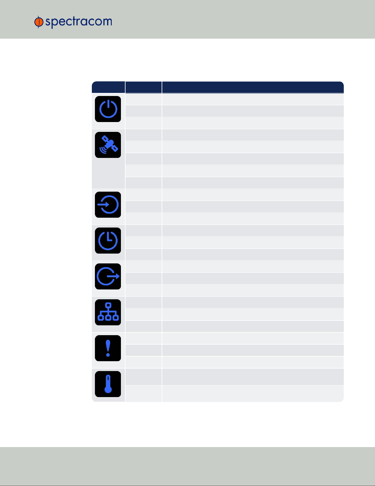
1.3.3 Legend, individual LEDs
Icon Light Meaning
OFF No power
HEARTBEAT Booting
ON Powered
OFF No GNSS reception (0 satellites)
HEARTBEAT GNSS acquisition in process (≥ 1satellite(s), or 1PPS OK, or Time OK
SLOW Jamming detected
FAST Antenna short circuit
ON GNSS is available as reference (1PPS and Time OK)
OFF Inputs not detected/all inputs are disabled
FAST 1 or more input is missing, or invalid timing on 1 or more input detected
ON Inputs are enabled
OFF Unit is in Holdover (valid)
ON System Clock OK (valid)
FAST Invalid Time (Holdover period exceeded, or oscillator damaged)
OFF No output signal(s) detected/all outputs are disabled
FAST Malfunction detected (short circuit, or overload)
ON Outputs are enabled
OFF No network detected
FAST Network malfunction detected (e.g., no auto-negotiation)
ON Network OK, configuration OK
OFF Unit OK
FAST Unit requires attention; check other status LEDs, see Web UI
HEARTBEAT See table
"LED Lighting Patterns" on the previous page
OFF Temperature OK
FAST High temperature detected
1.3 Status LEDs
Table 1-2:
Legend for Status LEDs
CHAPTER 1 • VersaSync User Manual Rev. 6.0
5
Page 18
1.4 Interfaces Overview
1.3.3.1 LED Patterns during Boot Sequence
For the first five seconds after power-up all LEDs will be OFF. Then the Power LED will be blinking before it will be lit permanently. If you have configured your unit to operate in Blackout
Mode, this will take effect once the blinking cycle ends.
1.3.4 Blackout Mode
All LEDs can be turned off via the WebUI.
The LED brightness level can be set from 63 (as bright as possible) to 0 (not visable).
To disable all LED activity via the WebUI:
Navigate to MANAGEMENT > OTHER: LED Configuration, and set the Brightness level to
"0".
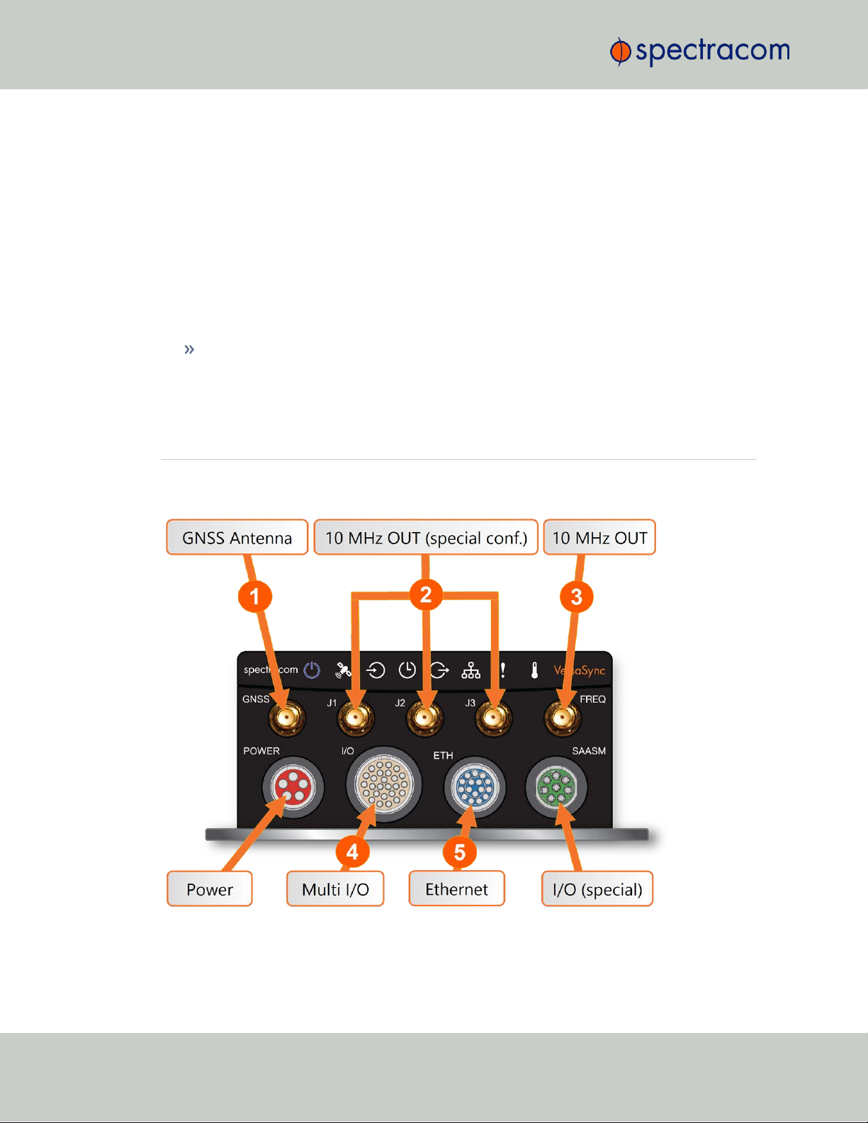
1.4 Interfaces Overview
All of VersaSync's interfaces are integrated into the unit's connectors, which are located on the
front panel:
Figure 1-2: VersaSync front panel connectors
6
CHAPTER 1 • VersaSync User Manual Rev. 6.0
Page 19
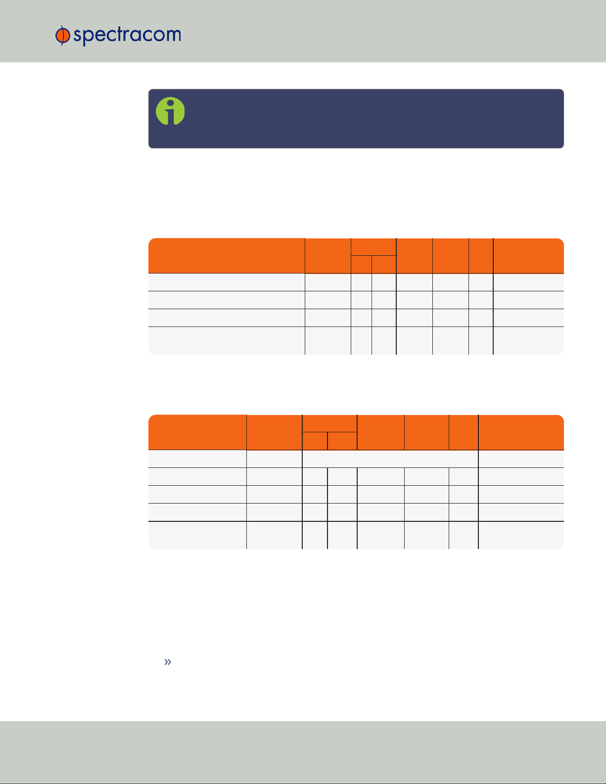
Note: VersaSync is highly configurable and the connections can be adjusted
INPUTSIGNAL
Total
available
DCLS
RS-232 RS-485 ETH
Connector No.
(see Fig. above)
TTL 10V
1PPS (1) 1 4
ASCII/HaveQuick/IRIG B (1) 1 4
ASCII/NMEA (1) 1 4
Network Interface (10/100/1000bT):
NTP (Stratum 2), PTP
(2) 1 5
OUTPUTSIGNAL
Total
available
DCLS
RS- 232 RS-485 ETH
Connector No.
(see Fig. above)
TTL 10V
10 MHz (1+3) SMA
2,
3
1PPS (2) 1 1 4
ASCII/HaveQuick (1) 1 4
ASCII/NMEA (1) 1 4
NTP server,
PTP v2 master
(1) 1 5
many different ways. Your interface configuration may vary based on options
you selected during the ordering process.
The following interfaces are provided:
1.4.1 Input Timing Interfaces
1.4 Interfaces Overview
Table 1-3:
VersaSync inputs
1.4.2 Output Timing Interfaces
Table 1-4:
VersaSync outputs
All Multi I/O interfaces (connector no. 4) are software-configurable, see "Assigning I/O Pins"
on page36.
For additional information on configuring pinouts, see "Connectors and their Pinouts" on the
next page and "Configuring I/O Settings" on page40.
1.4.3 Other Interfaces
CHAPTER 1 • VersaSync User Manual Rev. 6.0
USB serial equivalent: CLI interface (Connector 4)
7
Page 20
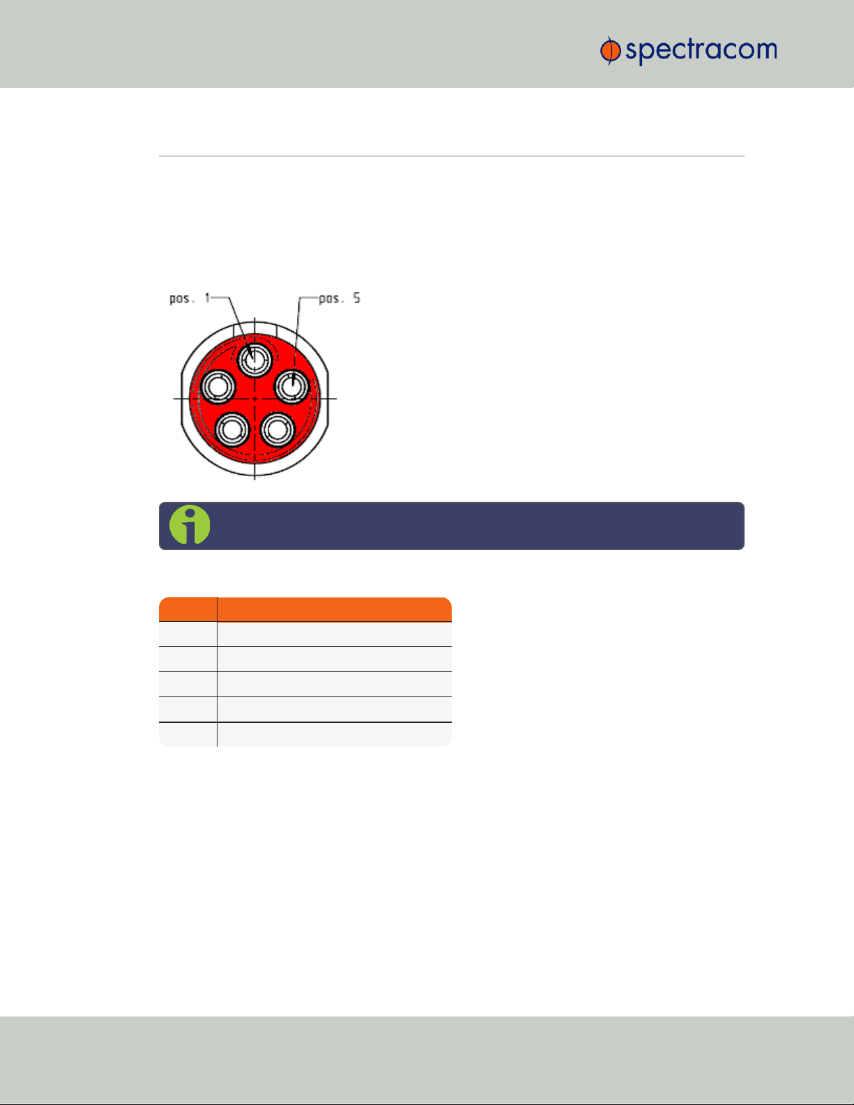
Pin Signal
1 V
Main
(10 to 32V)
2 V
Main
(10 to 32 V)
3 V
Batt
(10 to 32 V)
4 GND
5 GND
1.5 Connectors and their Pinouts
1.5 Connectors and their Pinouts
All of VersaSync's connectors are provided at the front panel of the unit, below the Status LEDs.
The Advanced Military Connectors are keyed for foolproof connectivity and offer a push-pull
locking mechanism.
1.5.1 Power Connector
Note: View in mating direction from front.
Table 1-5:
Power connector pinout
1.5.2 Input/Output Connector
VersaSync has a 26- pin input/output connector that offers 8 software- configurable
CHANNELS, plus one fixed DCLS channel, and a USB interface. To learn more about types of
interfaces and signals, and how to configure them, see "Assigning I/O Pins" on page36.
8
CHAPTER 1 • VersaSync User Manual Rev. 6.0
Page 21
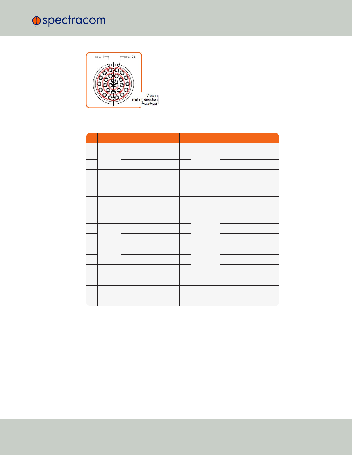
Pin Channel Signal Pin Channel Signal
1
0 1PPS output (5V)
15
7 Have Quick output (RS-
485 signal +)
2
GND
16
GND
3
1 HaveQuick input (RS-
485 signal +)
17
8 Have Quick output (RS-
485 signal –)
4
GND
18
GND
5
2 HaveQuick input (RS-
485 signal –)
19
9
(USB ded-
icated)
GND
6
GND
20
GND
7
3 1PPS output (10 V)
21
Not connected
8
GND
22
GND
9
4 ASCII output (RS-232)
23
USB D–
10
GND
24
GND
11
5 1PPS input
25
USB D+
12
GND
26
GND
13
6 ASCII input (RS-232)
14
GND
1.5 Connectors and their Pinouts
Table 1-6:
Default I/O connector pinout
CHAPTER 1 • VersaSync User Manual Rev. 6.0
9
Page 22
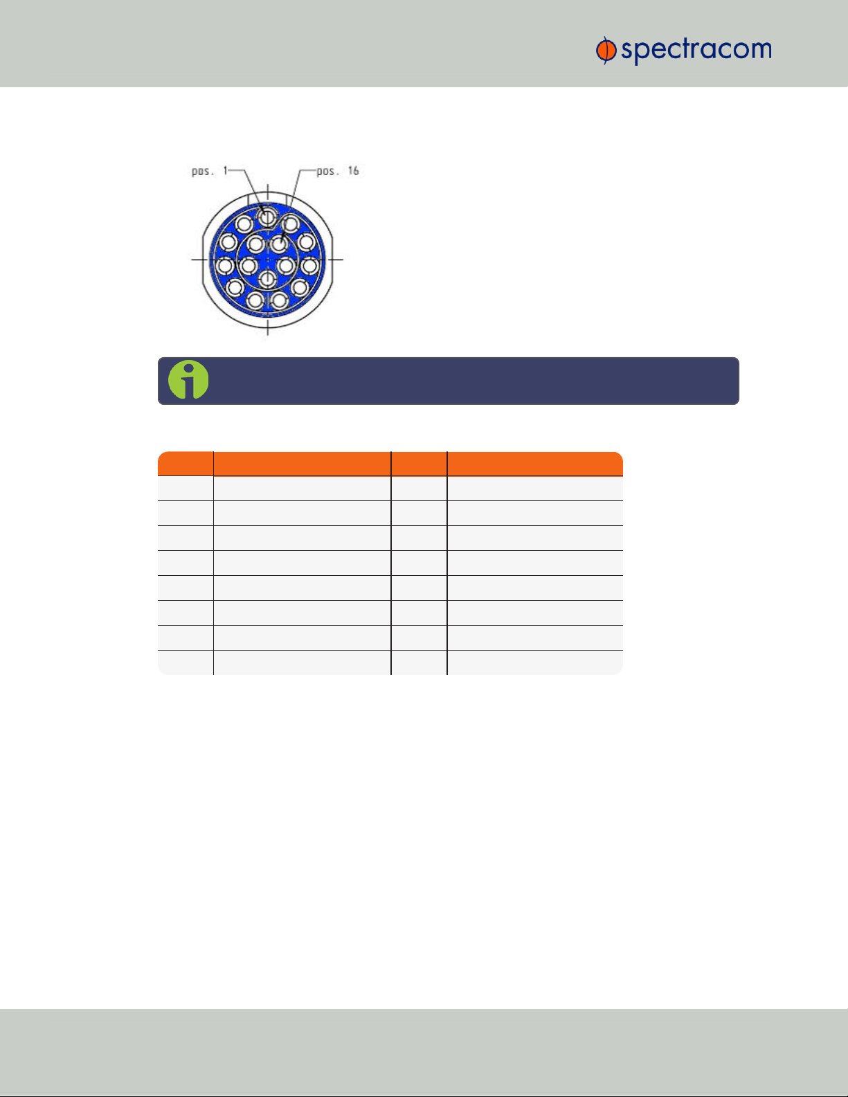
Pin Signal Pin Signal
1 Ethernet_1 A+ 9 Ethernet_2 A+
2 Ethernet_1 A– 10 Ethernet_2 A–
3 Ethernet_1 B+ 11 Ethernet_2 B+
4 Ethernet_1 B– 12 Ethernet_2 B–
5 Ethernet_1 C+ 13 Ethernet_2 C+
6 Ethernet_1 C– 14 Ethernet_2 C–
7 Ethernet_1 D+ 15 Ethernet_2 D+
8 Ethernet_1 D– 16 Ethernet_2 D–
1.5 Connectors and their Pinouts
1.5.3 Ethernet Connector
Note: View in mating direction from front.
Table 1-7:
Ethernet connector pinout
1.5.4 Optional I/O Connector
The Optional I/O connector is used in conjunction with the Option Board that is available for
VersaSync. If the unit is not equipped with an Option Board, this connector is not used.
1.5.5 Coaxial Connectors
VersaSync offers five (5) coaxial connectors, three (3) of which can be configured at the factory to accommodate requirements for e.g., IRIG AM signals or additional 10MHz outputs. The
minimum configuration includes the GNSS antenna and a 10MHz sinewave output.
Unless otherwise ordered at the factory, all coaxial connectors (aside from the GNSS connection) produce a 10MHz output that is not software configurable.
All coaxial connectors are standard SMA connectors.
10
CHAPTER 1 • VersaSync User Manual Rev. 6.0
Page 23
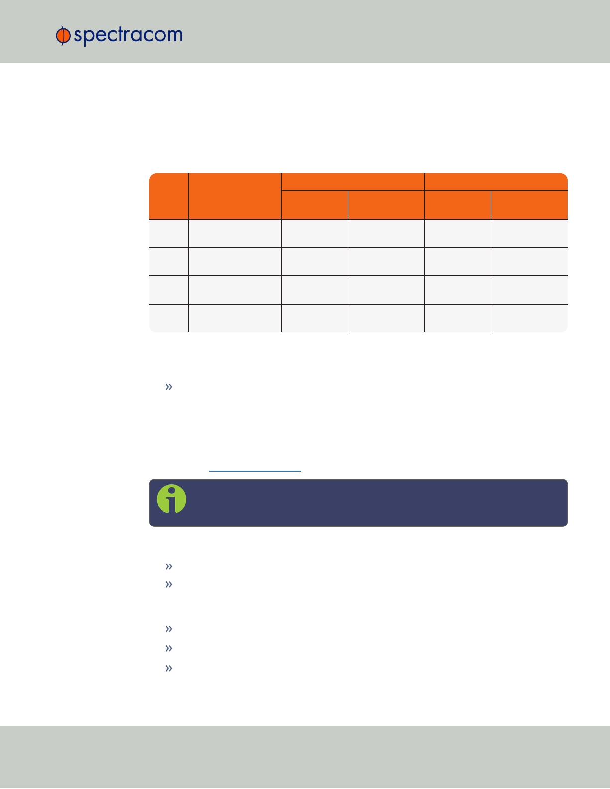
Ref Description
VersaSync Connector Mating (Cable) Connector
Spectracom
Part No.
ODU Part No.
Spectracom
Part No.
ODU Part No.
POWER Power connector,
5pin
J240R-0051-
002Q
GK1YBR-
P05UJ00-000L
P240R-0051-
002Q
S11YBRP05XJG0-0000
I/O I/O connector, 26
pin
J240R-0261-
002F
GK2YAR-
P26UC00-000L
P240R-0261-
002F
S12YARP26XCD0-0000
ETH Ethernet connector,
16 pin
J240R-0161-
002F
GK1YCR-
P16UC00-000L
P240R-0161-
002F
S11YCRP16XCD0-0000
SAASM Optional I/O con-
nector, 8 pin
J240R-0081-
012F
GK1YDR-
P08UF00-000L
P240R-0081-
002F
S11YDRP08XFG0-0000
1.5 Connectors and their Pinouts
Mating Connector Plugs
The table below lists the part numbers for the mating connectors. The connectors can be
ordered through Spectracom or ODU-USA Inc. All connectors are circular ODU AMC®"miltype" connectors.
Table 1-8:
Connector Part Numbers
1.5.5.1 ODU®ordering contact information (USA):
ODU-USA Inc.
4010 Adolfo Road
Camarillo, CA 93012
United States of America
Phone: +1 (805) 484 0540
Fax: +1 (805) 484 7458
Email: sales@odu-usa.com
CHAPTER 1 • VersaSync User Manual Rev. 6.0
Note: Building the mating cables requires special tools. Contact ODU for cable
assemblies. Be advised that typical lead times are 12 to 16 weeks.
ETHERNET connector wiring:
1 through 8: A Ethernet Connect, 4 pairs, 1000bT
9 through 16: B Ethernet Connect, 4 pairs, 1000bT
POWER connector pinout
1; 2: V
3: V
Batt
4; 5: Ground return
, 10 to 32 V
Main
, 10 to 32 VDC(Standby Power)
DC
11
Page 24
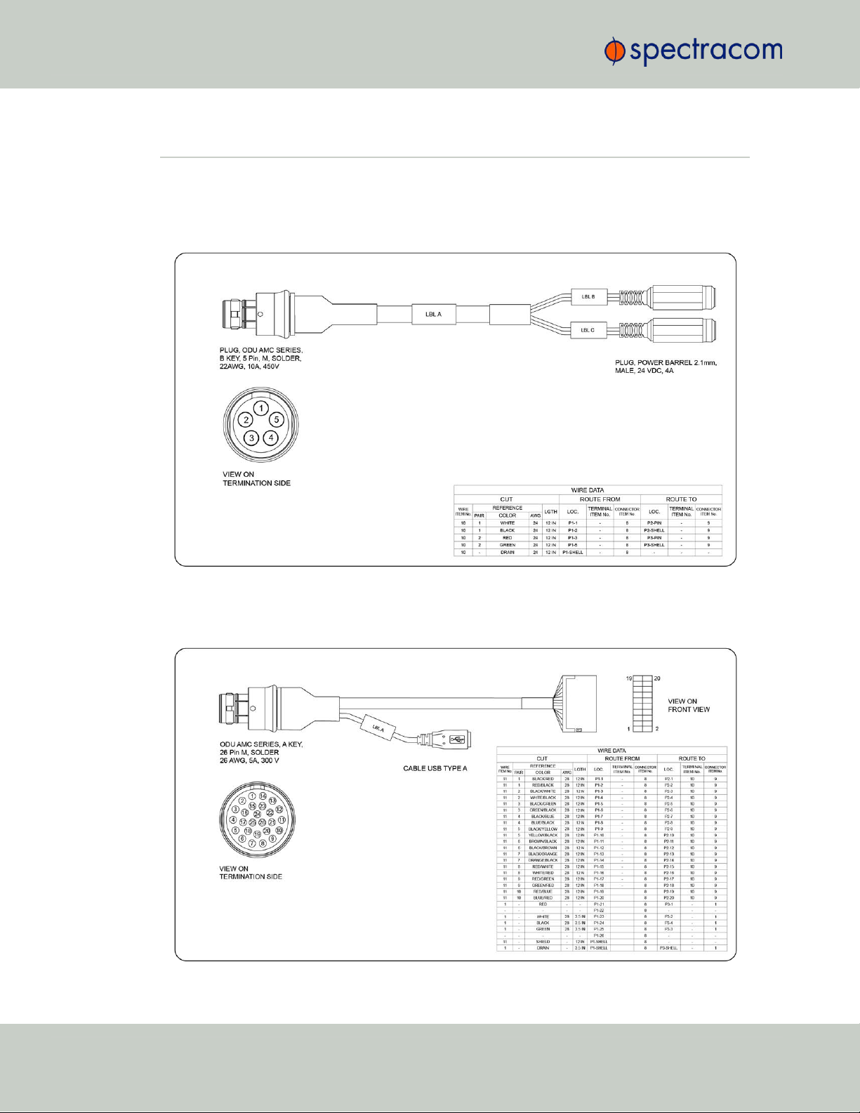
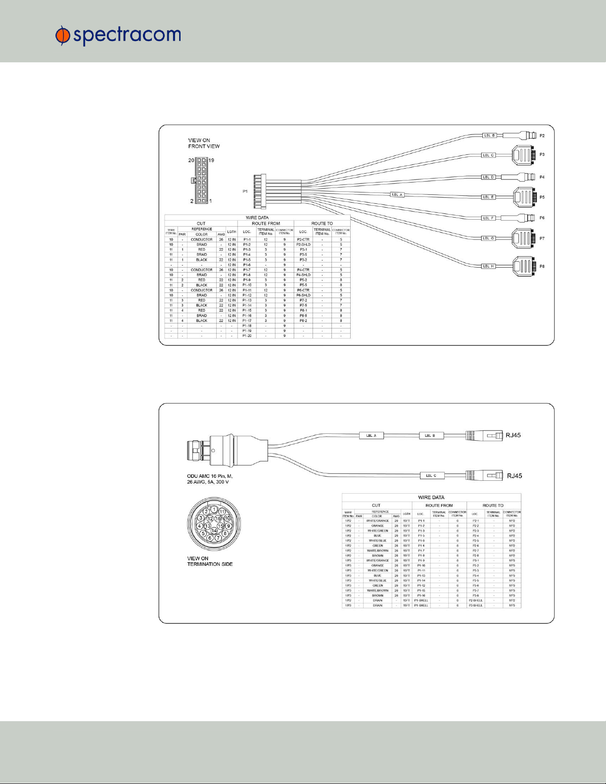
1.6 Included Cables
1.6 Included Cables
The VersaSync Evaluation Kit contains the following cables (the antenna cable is not shown):
Power Cable
I/O Cable
12
CHAPTER 1 • VersaSync User Manual Rev. 6.0
Page 25
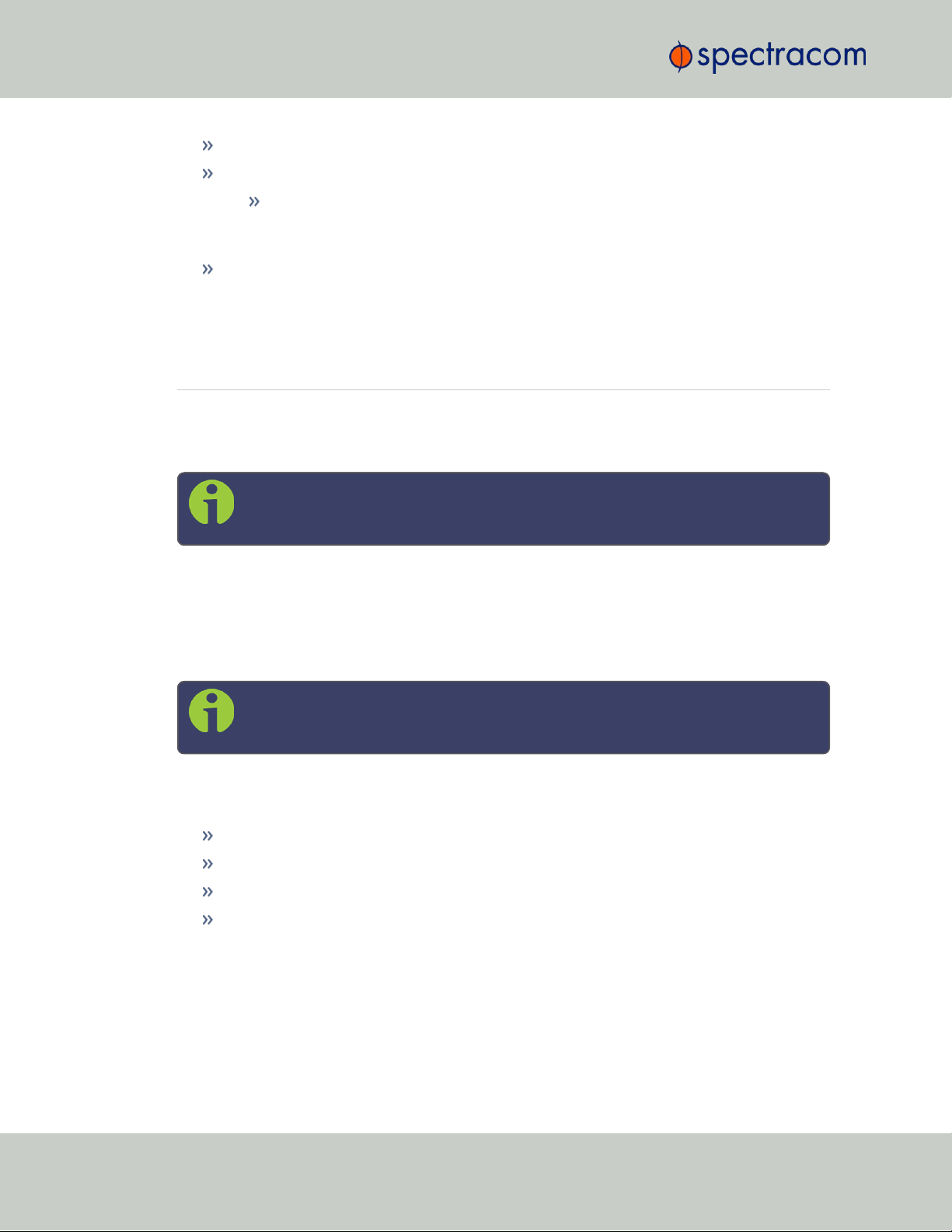
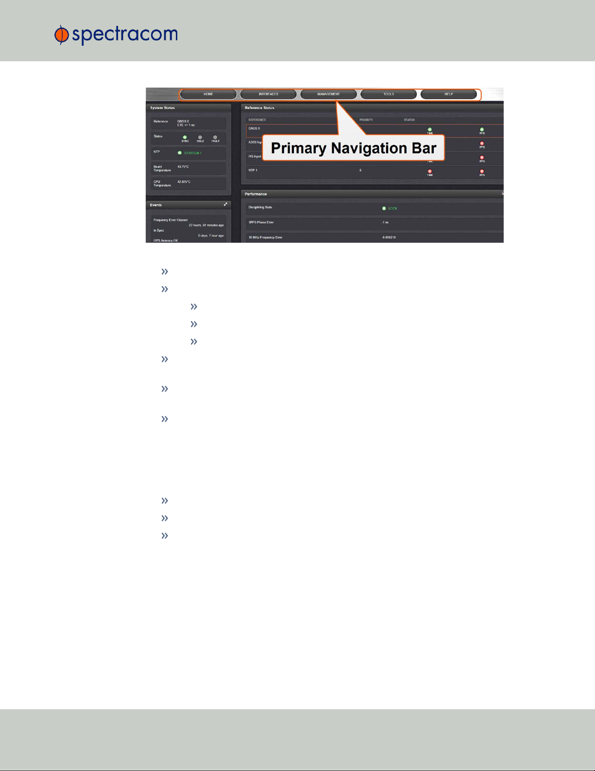
I/O Breakout Cable
1.6 Included Cables
Ethernet Data Cable
CHAPTER 1 • VersaSync User Manual Rev. 6.0
13
Page 26

1.7 VersaSync Specifications
1.7 VersaSync Specifications
1.7.1 Supply Power
Operating Power and Standby Power: 10 to 32 V
Power draw:
Operating: 10 W typical
Standby: 0.4W
1.7.2 GNSS Receiver
VersaSync has an integrated state-of-the-art GNSS receiver, suitable for concurrent dual-constellation reception.
Compatible signals:
GPS L1 C/A (center frequency 1575.42 MHz)
GLONASS L10F (center frequency 1602.0 MHz)
Galileo E1 B/C (center frequency 1575.42 MHz)
QZSS L1-SAIF (center frequency 1575.42 MHz)
BeiDou B1 (center frequency 1561.098 MHz)
Satellites tracked: Up to 72 simultaneously
Update rate: up to 2Hz (concurrent)
Acquisition time: Typically <27seconds from cold start
Antenna requirements: Active antenna module, +5V, powered by VersaSync, 16dB gain min-
imum
Antenna connector: SMA
DC
14
CHAPTER 1 • VersaSync User Manual Rev. 6.0
Page 27

1.7.3 Mechanical & Environmental Specifications
1.7.3.1 Physical Specifications
Dimensions (W x D x H): 147.3x 127.5 x 63.0 mm (5.8 x 5x 2.5 in)
1.7 VersaSync Specifications
Figure 1-3: Mechanical dimensions
Mounting: Bolted to a metal plate, using 6 through holes
Weight: 0.91 kg (2.0 lbs)
1.7.3.2 Environmental Requirements
Temperature, in operation: -40°C to +65°C
Temperature, in storage: -45°C to +85°C
Humidity: 95% RH, non condensing at 40°C
Altitude: up to 45,000 ft
CHAPTER 1 • VersaSync User Manual Rev. 6.0
15
Page 28
1.8 The VersaSync Web UI
Protection: IP 65
Vibration:
7.7 g rms, 20 to 1000 Hz (in accordance with MIL-STD 810G, Method 214.6 Category 24: Minimum Integrity and Helicopter Minimum Integrity, see graphs
514.7E-1 and 514.7E-2)
Shock: 20 g, 11 ms (pulse sawtooth) in accordance with MIL-STD 810G, Method 516.7
Procedure1
1.8 The VersaSync Web UI
VersaSync has an integrated web user interface (referred to as "WebUI" throughout this documentation) that can be accessed from a network-connected computer, using a standard web
browser. The WebUI is used to configure and monitor the unit.
Note: An integrated Command-Line Interpreter interface (CLI) allows the use of a
subset of commands that are integrated into the Web UI.
The minimum browser requirements for the Web UI are: Internet Explorer®9 or higher,
Firefox®, or Chrome®.
1.8.1 The Web UI HOME Screen
Note: Screens displayed in this manual are for illustrative purposes. Actual
screens may vary depending upon the configuration of your product.
The HOME screen of the VersaSync web user interface ("Web UI") provides comprehensive
status information at a glance, including:
vital system information
current status of the references
key performance/accuracy data
major log events.
The HOMEscreen can be accessed from anywhere in the Web UI, using the HOMEbutton in
the Primary Navigation Bar:
16
CHAPTER 1 • VersaSync User Manual Rev. 6.0
Page 29
The Primary Navigation Bar provides access to all menus:
HOME: Return to the HOME screen (see above)
INTERFACES: Access the configuration pages for …
… references (e.g., GNSS, NTP)
1.8 The VersaSync Web UI
… outputs (e.g. 10 MHz, PPS, NTP) and
… installed input/output option cards.
MANAGEMENT: Access the NETWORK setup screens, and OTHER setup screens e.g., to
configure Reference Priorities, System Time, and the Oscillator.
TOOLS: Opens a drop-down menu for access to the system maintenance screens and sys-
tem logs.
HELP: Provides Spectracom Service Contact Information and high-level system con-
figurations you may be required to furnish when contacting Spectracom Service.
1.8.2 The INTERFACES Menu
The INTERFACES menu on the Main screen provides access to VersaSync's:
External REFERENCES e.g., the GNSS reference input
Detected OUTPUTS, such as 10 MHz and 1PPS
Installed OPTIONS.
CHAPTER 1 • VersaSync User Manual Rev. 6.0
17
Page 30
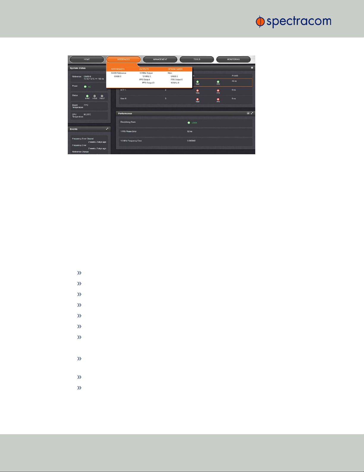
1.8 The VersaSync Web UI
Clicking on any of the line items will open a status screen, providing real-time information on
the selected interface e.g., availability, performance data and events history.
To configure settings for the selected interface, click the GEAR icons or buttons provided on
most of the status screens. Icons like the INFO symbol provide access to more detailed status
information and history data.
The headings of each of the INTERFACES drop-down menus (white on orange) open overview
status screens for the respective menu items.
1.8.3 The Configuration MANAGEMENT Menu
The MANAGEMENT menu on the Web UI's Main screen provides access to VersaSync's con-
figuration screens and settings.
On the left side, under NETWORK, the following standard setup screens can be found:
Pin Layout
Network Setup
SSH Setup
SNMP Setup
NTP Setup
PTP Setup
GPSD Setup
Under OTHER, you can access non-network related screens:
Authentication: Manage user accounts, Security Policy, LDAP Setup, RADIUS setup, Login
Preference and Remote Servers. Change My Password is also available.
Reference Priority: Define the order of priority for timing inputs.
Notifications: Configure the notifications triggered by VersaSync’s events. A notification
can be a combination of a mask alarm and/or SNMP Trap and/or email.
18
CHAPTER 1 • VersaSync User Manual Rev. 6.0
Page 31

Time Management: Manage the Local Clock, UTC Offset, DST Definition and Leap
Second information.
System Time Message: Configure a regularly delivered message of the system time.
Log Configuration: Manage the system logs.
Disciplining: Manage oscillator disciplining.
LED Configuration: Change the LEDbrightness.
Change My Password: Configure the admin password.
1.8.4 The TOOLS Menu
The TOOLS menu on the Web UI's Main screen provides access to:
The System Upgrade screen
System and network monitoring screens
Miscellaneous system administration screens
Log screens
1.8 The VersaSync Web UI
CHAPTER 1 • VersaSync User Manual Rev. 6.0
19
Page 32

1.9 SAFETY: Before You Begin Installation
SAFETY
Table 1-9:
Symbol Signal word Definition
Safety symbols used on this product or in this document
Potentially dangerous situation which may lead to personal
DANGER!
CAUTION!
NOTE
ESD
CHASSIS GROUND
Analog Ground
Recycle
injury or death! Follow the instructions closely.
Potential equipment damage or destruction!
Follow the instructions closely.
Tips and other useful or important information.
Risk of Electrostatic Discharge!
Avoid potential equipment damage by following ESD Best
Practices.
This symbol is used for identifying the functional ground of an
I/O signal. It is always connected to the instrument chassis.
Shows where the protective ground terminal is connected
inside the instrument. Never remove or loosen this screw!
Recycle the mentioned components at their end of life. Follow
local laws.
1.9 SAFETY: Before You Begin Installation
This product may constitute a risk to the operator or installation/maintenance personnel, if used
under conditions that must be deemed unsafe, or for purposes other than the product's designated use, which is described in the introductory technical chapters of this guide.
DANGER! If the equipment is used in a manner not specified by the manufacturer,
the protection provided by the equipment may be impaired.
Before you begin installing and configuring this product, carefully read the following important
safety statements. Always ensure that you adhere to any and all applicable safety warnings,
guidelines, or precautions during the installation, operation, and maintenance of your product.
20
CHAPTER 1 • VersaSync User Manual Rev. 6.0
Page 33

1.10 SAFETY: User Responsibilities
DANGER! — INSTALLATION OF EQUIPMENT:
Installation of this product is to be done by authorized service personnel
only.This product is not to be installed by users/operators without legal authorisation.
Installation of the equipment must comply with local and national electrical codes.
DANGER! — DONOTOPENEQUIPMENT, UNLESSAUTHORIZED:
The interior of this equipment does not have any user serviceable parts. Contact
Spectracom Technical Support if this equipment needs to be serviced. Do not
open the equipment. Follow Spectracom Safety Instructions, and observe all local
electrical regulatory requirements.
Caution: Electronic equipment is sensitive to Electrostatic Discharge (ESD).
Observe all ESD precautions and safeguards when handling Spectracom equipment.
1.10 SAFETY: User Responsibilities
The equipment must only be used in technically perfect condition. Check components for
damage prior to installation. Also check for loose or scorched cables on other nearby
equipment.
Make sure you possess the professional skills, and have received the training necessary
for the type of work you are about to perform.
Do not modify the equipment.
Use only spare parts authorized by Spectracom.
Always follow the instructions set out in this User Manual , or in other Spectracom documentation for this product.
Observe generally applicable legal and other local mandatory regulations.
CHAPTER 1 • VersaSync User Manual Rev. 6.0
21
Page 34

1.11 SAFETY: Other Tips
1.11 SAFETY: Other Tips
Keep these instructions at hand, near the place of use.
Keep your workplace tidy.
Apply technical common sense: If you suspect that it is unsafe to use the product, do the
following:
Disconnect the supply voltage from the unit.
Clearly mark the equipment to prevent its further operation.
22
CHAPTER 1 • VersaSync User Manual Rev. 6.0
Page 35

SETUP
The following topics are included in this Chapter:
2.1 Installation Overview 24
2.2 Initial Network Setup 27
2.3 Zero Configuration Setup 30
2.4 Accessing the WebUI 31
2.5 Setting up an IP Address 32
2.6 Configuring Inputs/Outputs 35
2.7 Configuring Network Settings 54
CHAPTER 2
CHAPTER 2 • VersaSync User Manual
23
Page 36

Requirement Action Evaluation kit cable
USB connection
Connect USB to the Multi I/O
connector.
Connect the USB connector to a PC with a terminal
emulator program (CA08R-CRUB-0002)
Network
connection
Connect at least one of the
two Ethernet connectors to a
network.
Connect the RJ45 jack labeled ETH0 or ETH1 to a
network hub/switch or directly to a PC (CA08RCRET-0002)
2.1 Installation Overview
2.1 Installation Overview
The steps that need to be performed prior to putting VersaSync into service include:
Installation: Hardware setup, mechanical installation, physical connections.
Setup: Establish basic access to the unit, so as to allow the use of the web user interface
("WebUI").
Configuration: Access the Web UI, configure the network, input and output references,
protocols (e.g., NTP), other settings.
Not all of the setup steps described in this manual may apply to you. Your unit installation relative to other connected devices, the cable selection and manufacturing, your chosen power
source, your project-specific infrastructure, and your planned access to your unit (either WebUI
or CLI), could all affect your setup needs.
2.1.1 Hardware Connections
During the procedure described below, you will connect the Power cable, the Multi I/O cable,
and the Ethernet cable.
The step-by-step instructions below outline the VersaSync installation and configuration process:
1.
Install VersaSync in the designated vehicle:
Ground the unit by connecting the DC negative terminals to the chassis of the unit,
and to the vehicle metallic structure.
The mounting plate should be in direct contact with the unit base plate, so as to
conduct heat.
For more detail on mounting your unit, see "Mounting" on the facing page.
2.
Install the GNSS antenna(s).
3.
Wire the antenna cables and interface cables. Most customers will require the Multi I/O
and Ethernet cables for these connections, as well as a PC..
USB: Connect the Multi I/O connector to the VersaSync unit. If you are using the
Evaluation Kit, connect the Multi I/O USB output to a PC. Install a terminal emu-
lator program on the PC (e.g., TeraTerm
®
or PuTTY®).
24
CHAPTER 2 • VersaSync User Manual Rev. 6.0
Page 37

Requirement Action Evaluation kit cable
Power up Connect 12 VDCto the
power connector.
Attach a cable and apply 12 VDCto the plug labeled
"Main" (CA08R-CRPB-0002)
2.1 Installation Overview
Ethernet: Connect the Ethernet cable to the ETH port of the unit. If you are using
the Evaluation Kit, connect at least one of the two I/O cable Ethernet ports (ETH0
or ETH1) to a network switch/hub, or to the PC mentioned above (using a standard Ethernet patch cable, or a crossover cable.)
For pinout tables, see "Connectors and their Pinouts" on page8 and "Configuring Inputs/Outputs" on page35.
4.
Connect the power supply . The unit will power up, and the ON/OFF status LED will
pulsate.
5.
Establish a network connection so as to allow access to the web user interface ("Web UI").
See "Initial Network Setup" on page27 for information on the USB driver installation
and network address configuration.
Note: On a DHCP network, you can also use Zeroconf to access the Web
UI (see "Zero Configuration Setup" on page30).
6.
Using the Web UI, configure the following:
Software-configurable I/O pins, see "Assigning I/O Pins" on page36.
Other VersaSync INTERFACES settings and MANAGEMENT settings e.g., network
settings, reference priorities (see "Configuring Network Settings" on page54).
2.1.2 Mounting
2.1.2.1 Selecting a Mounting Location
The unit is to be mounted on a plate, using six (6) through holes. The mounting location must
offer sufficient space to accommodate the unit and the cable connectors, and it must be within
cable reach to other connected devices, such as the GNSS antenna. The unit can be mounted
horizontally, or at any angle. The chosen environment must not fall below IP 65 ingress protection standards.
CHAPTER 2 • VersaSync User Manual Rev. 6.0
25
Page 38

2.1 Installation Overview
Figure 2-1: Mechanical dimensions
2.1.2.2 Heat Dissipation
The aluminum base plate of the unit acts as a heat drain, conducting heat away from VersaSync's interior components. When considering a mounting location, it is crucial that:
the operating temperature of the mounting surface does not exceed 65°C/149°F.
the mounting surface is even and heat conductive. Do not use any insulator material e.g.,
rubber gaskets or similar.
the ambient air temperature meets is within the specified range, i.e. -40°C to +65°C.
2.1.2.3 Fasteners
Spectracom recommends to observe the VITA 75 standard regarding mounting the unit, and
fastener selection.
26
CHAPTER 2 • VersaSync User Manual Rev. 6.0
Page 39

2.1.2.4 Grounding
The unit can be grounded in two different ways:
By connecting the DC negative terminals to the chassis of the unit, and to the vehicle
metallic structure. This option is the factory standard for VersaSync.
By isolating the DC negative terminals from the chassis of the unit ("airborne mode").
This option must be requested at the time of ordering your unit.
2.2 Initial Network Setup
After making the hardware connections outlined in the Installation Overview list, the following
information will help you to establish a network connection.
VersaSync has a Command Line Interpreter ("CLI"). Using the CLI connection, you can set up
access to the web user interface ("Web UI") that is used to configure and monitor the unit. You
will need a terminal emulator program installed on the PC that will be used to configure Ver-
saSync in order to communicate. See "Setting up a Terminal Emulator" on page240 for more
detailed instructions.
2.2 Initial Network Setup
Default settings:
VersaSync network settings default to DHCP: if the unit is connected to a DHCP server via ETH0
or ETH1, it will accept an assigned dynamic IP address.
In order to apply a static IP address, DHCP must be disabled. (See "Assigning a Static IP
Address" on page33).
Note: VersaSync supports zeroconf: If you have a DHCP enabled network, you
can use zeroconf for initial setup. For more information, see "Zero Configuration
Setup" on page30. Otherwise follow the instructions below for conventional
setup.
2.2.1 USB Driver
On the PC connected to the unit, new hardware (the USB interface) will be detected. The
correct driver should be installed automatically. If not, download the driver from
www.ftdichip.com/Drivers/VCP.htm, and install it manually via the instructions for
your operating system.
CHAPTER 2 • VersaSync User Manual Rev. 6.0
27
Page 40

2.2 Initial Network Setup
2.2.2 Network Address
a.
Start the terminal emulator program on the PC. Select the COM port that is assigned to
the USB interface:
Access the CLI via ssh or telnet: The required port configuration is 115200 8N1:
28
Press the Return key, and enter the login credentials:
CHAPTER 2 • VersaSync User Manual Rev. 6.0
Page 41

2.2 Initial Network Setup
Note: The default login credentials are:
User name = spadmin
Password = admin123 (will not be displayed on the screen)
b.
If you are on a DHCP-enabled network, retrieve the IP address assigned to VersaSync
by typing the net4 command. The command should return the network settings, includ-
ing the IP address assigned to the unit. Take note of the IP address.
You can use this IP address to login to the VersaSync Web UI and then set a static IP
address, subnet mask and gateway. (This can also be done via the CLI and a terminal
emulator. See "Assigning a Static IP Address" on page33).
Or, continue with the network configuration via the CLI, as described under Step c.
below.
Note: For your reference, the command helpcli produces a list of available
commands. Press the space key to display the next page, or the b key to
display the previous page.
Note: Should it become necessary to leave the VI editor mode (indicated
by a command line prompt ":"), press Q, or Ctrl C.
For more detailed information about setting a static IPaddress for your unit, see "Setting up an
IP Address" on page32
Next, proceed to "Accessing the WebUI" on page31.
CHAPTER 2 • VersaSync User Manual Rev. 6.0
29
Page 42

2.3 Zero Configuration Setup
2.3 Zero Configuration Setup
As an alternative to the conventional network configuration, VersaSync can also be set up using
the zero-configuration networking technology ("zeroconf").
Note: Zeroconf only works on DHCP-enabled networks.
When using zeroconf, a TCP/IP network will be created automatically, i.e. without the need for
manual configuration: Once VersaSync's ETH connector is connected to a hub, you can directly
access the VersaSync WebUI, using a standard web browser, without any configuration.
This is made possible because zeroconf utilizes these technologies:
Automatic allocation of network addresses for all connected devices
Automatic distribution and resolution of computer hostnames
Automatic detection of all available network services.
For more information on zeroconf and the multicast Domain Name System, see
https://en.wikipedia.org/wiki/Multicast_DNS.
Zeroconf Requirements
Prior to using zeroconf, ensure the following requirements are met:
Your LAN network must have DHCP enabled.
Your VersaSync unit must have DHCP enabled for its ETH0 port (this is the factory
default setting)
Note: Zeroconf is only supported on the ETH0 port.
Check the serial number label on the side of the unit, and write down the last 6 digits of
the MAC 0 address e.g., "0C 00 19"
Windows 7/8 users should install Bonjour Print Services, otherwise access to *.local
addresses will not be possible.
Windows 10 already supports mDNS and DNS-SD, hence there is no need to install
additional software.
30
CHAPTER 2 • VersaSync User Manual Rev. 6.0
Page 43

2.3.1 Using Zeroconf
Connect to the Web UI of your VersaSync unit in these 3 steps:
1.
Connect VersaSync to a router on your LAN via the ETH connector (see "Initial Network
Setup" on page27).
2.
Connect the power supply to the VersaSync unit.
3.
On a connected computer, open your web browser and in the URL field type the following:
where [xxxxxx] are the last six digits of the MAC0 address you copied from the serial
number label on the unit.
You should now be prompted for a username and password. The factory default credentials are:
2.4 Accessing the WebUI
versasync-[xxxxxx].local/
Username: spadmin
Password: admin123
Note: If you do not have physical access to the unit, you can obtain the MAC
address also by accessing VersaSync's CLI via the I/O connector USB port, using
e.g., the ifconfig command.
Once you logged into the VersaSync via zeroconf, you can retrieve the DHCP address for
future use:
Navigate to MANAGEMENT: NETWORK > Network Setup, and click General Settings in
the Actions panel on the left. The IPV4 ADDRESS will be displayed for each port on the
bottom of the window.
2.4 Accessing the WebUI
VersaSync's WebUI is the recommended tool to interact with the device, since it provides
access to nearly all configurable settings, and obtain comprehensive status information without
having to use the Command Line Interpreter (CLI).
You can access the Web UI either by using the automatically assigned DHCP IP address, or by
using a manually set static IP address (see "Assigning a Static IP Address" on page33).
1.
On a PC connected to VersaSync via ETH1 or ETH0, start a web browser.
2.
Navigate to the IP address assigned in "Initial Network Setup" on page27.
3.
Log into the Web UI as an administrator. The factory-default administrator user name
CHAPTER 2 • VersaSync User Manual Rev. 6.0
31
Page 44

2.5 Setting up an IP Address
and password are:
Username: spadmin
Password: admin123
Note: For security reasons, it is advisable to change the default credentials,
see: "Managing Passwords" on page193.
4.
Upon initial login, you will be asked to register your product. Spectracom recommends
to register VersaSync, so as to receive software updates and services notices. See also
"Product Registration" on page285.
2.5 Setting up an IP Address
In order for VersaSync to be accessible via your network, you need to assign an IP address to
VersaSync, as well as a subnet mask and gateway, unless you are using an address assigned
by a DHCP server.
Note: Unless you are using DNS in conjunction with DHCP (with the client con-
figured using VersaSync's hostname instead of IP address), Spectracom recom-
mends to disable DHCP, and instead use a static IP address. Failure to do this can
result in a loss of time synchronization, should the DHCP server assign a new
IPaddress to the unit.
Before you continue …
… please obtain the following information from the system network administrator:
Available static IP address
This is the unique address your network administrator will assign to your VersaSync unit. Make sure the chosen address is outside of the DHCP range of your
DHCP server.
Subnet mask (for the network)
The subnet mask defines the number of bits taken from the IP address that are used
in the network portion. The number of network bits used in the net mask can range
from 8 to 30bits.
Gateway address
The gateway (default router) address is needed if communication to the VersaSync is made outside of the local network. By default, the gateway is disabled.
32
CHAPTER 2 • VersaSync User Manual Rev. 6.0
Page 45

2.5.1 Assigning a Static IP Address
There are two ways to setup a permanent static IP address, after connecting VersaSync to a
DHCP network:
Assigning a Static IP Address Using the CLI:
Note: For your reference, the command helpcli produces a list of available com-
mands. Press the space key to display the next page, or the b key to display the
previous page. To leave the VI editor, press Q or Ctrl C.
Open the serial console (e.g., by using TeraTerm)
1.
Disable DHCP – Command: dhcp4set <x> off (where x is 0/1 for ETH0 and ETH1,
respectively).
2.
Set the static IP address – Command: ip4set <x>.<IP address>.<subnet
mask> Example: ip4set 0 10.2.100.245 255.255.0.0
2.5 Setting up an IP Address
If required, also set your gateway address: gw4set <x> <gateway address>
3.
Verify that the address has been accepted – Command: net
4.
If so required, turn DHCP back on – Command: dhcp4set [x] on
Assigning a Static IP Address Using the Web UI:
1.
Enter the assigned dynamic IP address obtained during setup ("Initial Network Setup" on
page27) into the address field of your browser (on a computer connected to the VersaSync network). If the network supports DNS, the hostname may also be entered instead
(the default hostname is "Spectracom"). The start screen of the VersaSync Web UI will be
displayed.
2.
Log into the Web UI as an administrator. The factory-default user name and password
are:
Username: spadmin
Password: admin123
3.
Disable DHCP by navigating to MANAGEMENT > Network Setup. In the Ports panel on
the right, click the GEAR icon next to the Ethernet Port you are using. In the Edit Ethernet
Port Settings window, uncheck the Enable DHCPv4 field. Do NOT click Submit or Apply
yet.
4.
In the fields below the Enable DHCPv4 checkbox, enter the desired Static IP address, Netmask, and Gateway address (if required). Click Submit.
For subnet mask values, see "Subnet Mask Values" on the next page.
CHAPTER 2 • VersaSync User Manual Rev. 6.0
33
Page 46

Network Bits Equivalent Netmask Network Bits Equivalent Netmask
30 255.255.255.252 18 255.255.192.0
29 255.255.255.248 17 255.255.128.0
28 255.255.255.240 16 255.255.0.0
27 255.255.255.224 15 255.254.0.0
26 255.255.255.192 14 255.252.0.0
25 255.255.255.128 13 255.248.0.0
24 255.255.255.0 12 255.240.0.0
2.5 Setting up an IP Address
5.
To verify that the address has been accepted, enter the static IP address into the address
field of the browser and log into the WebUI again.
6.
If so required, turn DHCP back on (cf. Step 3), or continue with your configuration; see:
"Configuring Network Settings" on page54.
2.5.2 Subnet Mask Values
Table 2-1:
Subnet mask values
34
CHAPTER 2 • VersaSync User Manual Rev. 6.0
Page 47

Network Bits Equivalent Netmask Network Bits Equivalent Netmask
23 255.255.254.0 11 255.224.0.0
22 255.255.252.0 10 255.192.0.0
21 255.255.248.0 9 255.128.0.0
20 255.255.240.0 8 255.0.0.0
19 255.255.224.0
2.6 Configuring Inputs/Outputs
This Chapter covers the configuration of the inputs and outputs of the I/O connector.
When you configure an input our output via the I/O connector, you will need to adjust both
the pin configuration ("Assigning I/O Pins" on the next page) and (for some types) the settings
for that input or output via the Web UI ("Configuring I/O Settings" on page40).
2.6 Configuring Inputs/Outputs
Figure 2-2: I/O connector
For more information on the I/O connector, see "Connectors and their Pinouts" on page8.
Note: The GNSS input reference as well as the 10 MHz outputs are not fed into the
unit via the I/O connector and are therefore not explained in this Chapter; for
instructions on how to configure the GNSS reference, see "The GNSS Reference"
on page147 in the Chapter MANAGINGTIME.
Note: The Network Ports eth0 and eth1 can be configured under MANAGEMENT
> Network Setup. For more information, see "Configuring Network Settings" on
page54.
CHAPTER 2 • VersaSync User Manual Rev. 6.0
35
Page 48

2.6 Configuring Inputs/Outputs
2.6.1 Assigning I/O Pins
VersaSync's I/O connector is software configurable, i.e. the pin interfaces and the signal modulations can be configured by the user via the VersaSync WebUI.
The software-configurable 26-pin I/O connector comprises 9 user-configurable Channels, plus
one fixed USB interface. Channels can be used for the following input or output interfaces:
36
Figure 2-3: I/O configuration options
CHAPTER 2 • VersaSync User Manual Rev. 6.0
Page 49

2.6.1.1 Signal Types
DCLS, TTL DCLS, 10V RS485 RS 485, 120 Ω RS232
PPS out (5), in (2) out (1), in (1) out (4), in (4) in (4)
IRIG out (5), in (2) out (1), in (1) out (4), in (4) in (4)
HQ out (5), in (2) out (1), in (1) out (4), in (4) in (4)
GPIO out (5) out (1)
ASCII out (4), in (4) in (4) out (3), in (3)
The table below shows the maximum number of available interfaces for each signal type. Note
that you can assign only one signal for each pin pair, hence only four to nine input and output
signals can be transmitted/received at any given time. For details, see the signal mapping table
below.
2.6 Configuring Inputs/Outputs
Table 2-2:
Note: ASCII Time Code is abbreviated in the UI as ATC.
Available signal types
DCLS Signal Lines
Up to six TTL (5V) or 10V DCLS outputs and three DCLS inputs are available for e.g., 1PPS,
xPPS, IRIGB 00x, HaveQuick, ASCII ToD signal transmission.
Single-ended Serial Lines
VersaSync provides up to 3 RX and 3 TX RS232 interfaces for e.g., ASCII ToD – NMEA 0183
(ICD-GPS-153).
Differential Serial Lines
Up to four differential serial lines are available. Each of them can be set in either RS422 or
RS485 electrical standard, and used as input or output. One can be used in CAN mode. PPS
or Time-of-Day messages will be available, as well as HaveQuick and ICD GPS-060. Note that
this kind of interface uses two Channels.
Non-Configurable Pins
Channel # 0 provides a DCLSTTL output signal that is not user-configurable.
Also note that pins # 19 through 26 are reserved for the USB command line interface.
2.6.1.2 I/O Signal Mapping Table
Each Channel (i.e., each pin pair e.g., "3&4" = Channel 1) can serve as only one interface,
and not all combinations are possible due to the internal multiplexer architecture.
Spectracom provides an online interactive I/O switch matrix configurator that can be used to
design a custom I/O configuration:
CHAPTER 2 • VersaSync User Manual Rev. 6.0
http://manuals.spectracom.com/VSS/Content/VSS/SETUP/IOpinConfiguration.htm.
37
Page 50

2.6 Configuring Inputs/Outputs
The table below illustrates the signal combinations that can be assigned to the 18 configurable
pins.
Table 2-3:
Notes:
Pins to Channels (e.g., pins 3 & 4= Channel 1)
green = Signal Message Type can be assigned to this Channel (RS485 requires two Channels)
red = This Signal Message type cannot be assigned to this Channel
ATC = ASCII Time Code
I/O signal mapping to Channels
38
Configuring a new Input or Output
1.
In the VersaSync Web UI, navigate to MANAGEMENT > NETWORK: Pin Layout. The Pin
Layout screen will be displayed.
2.
Prior to assigning the new output, identify a pin pair in the pin Layout table that is not
used (Signal = "None") or not needed. You can Delete it, but you may also simply
assign the new PPS Output as described below, thus overwriting the existing Input or
Output.
3.
Add a pin configuration by clicking the PLUS icon in the top-right corner. The Add Pin
window will display.
4.
Start with the Type Filter drop-down menu (second line in the window) and select a signal
type.
5.
From the Signal drop-down menu, select a signal.
CHAPTER 2 • VersaSync User Manual Rev. 6.0
Page 51

2.6 Configuring Inputs/Outputs
6.
From the Pins drop-down menu in line 3, select the pin pair you chose in Step 2. (Note
that you will need 4 pins if you selected a RS485 signal Type.)
7.
Click Submit.
8.
In the Actions panel, click Apply Changes.
Restoring the Default I/O Configuration
VersaSync is shipped with a default I/O configuration that you can be customized. However, if
required you can restore the default configuration at any time after applying changes.
The following illustration shows the default I/O pin configuration:
Figure 2-4: Default I/O configuration
To restore the default I/O pin configuration:
A.
Navigate to the MANAGEMENT: NETWORK > Pin Layout screen.
B.
In the Actions panel on the left, click Restore Default Layout.
Reloading the Current I/O Configuration
To reload the currently used I/O configuration after adding pin layout changes, but before
clicking Apply Changes:
A.
Navigate to the MANAGEMENT: NETWORK > Pin Layout screen.
B.
In the Actions panel on the left, click Reload Layout.
CHAPTER 2 • VersaSync User Manual Rev. 6.0
39
Page 52

2.6 Configuring Inputs/Outputs
2.6.2 Configuring I/O Settings
Note: Illustrations shown below are examples; the windows displayed in your
Web UI may look differently.
2.6.2.1 How to Configure an Input Reference
To access the user-editable settings of an Input Reference, choose one of these two methods:
Configuring the settings of an input reference, method 1:
40
1.
Under INTERFACES > REFERENCES, click the desired reference.
2.
The Status window for the specific reference you selected will be displayed. Click the Edit button in the bottom-left corner.
3.
The settings window for the chosen reference will be displayed. Edit the field(s) as desired.
Configuring the settings of an input reference, method 2:
1.
In the INTERFACES > REFERENCES drop-down menu, click REFERENCES (white on orange), or
an input reference category (e.g., "GNSS reference").
2.
In the Status window, click the GEAR button next to the desired input reference.
3.
The settings window for the chosen reference will be displayed. Edit the field(s) as desired.
CHAPTER 2 • VersaSync User Manual Rev. 6.0
Page 53

2.6.2.2 How to Configure an Output
To access the user-editable settings of an Output, choose one of these two methods:
Configuring the settings of an output, method 1:
1.
Under INTERFACES > OUTPUTS, click the desired output.
2.
The Status window for the specific reference you selected will be displayed. Click the
Edit button in the bottom-left corner.
2.6 Configuring Inputs/Outputs
3.
The settings window for the chosen output will be displayed. Edit the field(s) as desired.
Configuring the settings of an output, method 2:
1. In the INTERFACES > OUTPUTSdrop-down menu, click OUTPUTS, or one of the output cat-
egories (not indented to the right)
2.
In the Status window, click the GEAR button next to the desired output.
3.
The settings window for the chosen output will be displayed. Edit the field(s) as desired.
2.6.3 Example: Configuring a 20 PPS Output
The instructions below explain how to configure a 20PPS output signal:
First, assign a GPIOoutput to an I/O pin pair:
1.
In the Web UI, navigate to MANAGEMENT > NETWORK: Pin Layout. The Pin Layout
screen will be displayed.
CHAPTER 2 • VersaSync User Manual Rev. 6.0
41
Page 54

2.6 Configuring Inputs/Outputs
2.
Prior to assigning the new output, identify a pin pair in the Pin Layout table that is not
used (Signal = "None") or not needed. You can Delete it, but you may also simply
assign the new PPS Output as described below, thus overwriting the existing Input or
Output.
3.
Add a pin configuration by clicking the PLUS icon in the top-right corner (1). The Add
Pin window will display.
4.
Start with the Type Filter drop-down menu (second line in the window) and select DCLS_
TTL.
5.
From the Signal drop-down menu, select GPIO_OUT DCLS_TTL.
6.
From the Pins drop-down menu in line 3, select e.g., pins 1,2.
7.
Click Submit.
8.
In the Actions panel, click Apply Changes.
Then, configure the settings for the newly created output:
9.
Navigate to INTERFACES > OUTPUTS > General Purpose Output/GP Output 0. The
GPOutput 0 status window will be displayed.
10.
Click Edit. The GPOutput 0 configuration window will be displayed.
11.
Under General, set the Output Mode to Square Wave, and check Output Enabled.
12.
To configure e.g., a 20 PPS signal, set the Pulse Width to 1 000 000 ns, and the Period
to 50 000 000 ns:
42
CHAPTER 2 • VersaSync User Manual Rev. 6.0
Page 55

2.6 Configuring Inputs/Outputs
13.
Click Submit.
2.6.4 Configurable I/Os
2.6.4.1 Configuring a 1PPS Input
To configure a 1PPS Input:
1.
Navigate to INTERFACES > REFERENCES: PPS Input 0 (or: INTERFACES >
OPTIONCARDS: PPS Input 0).
2.
The PPS Input 0 Status window displays. Click Edit to open the configuration window:
CHAPTER 2 • VersaSync User Manual Rev. 6.0
43
Page 56

2.6 Configuring Inputs/Outputs
3.
Apply your settings for:
Edge: [Rising, Falling] The on-time point of the 1PPS input can be configured to
be either the rising or falling edge of the 1PPS signal (by default, the rising edge
is the on-time point).
Offset: [-500000000 to 500000000 ns = ±0.5 s] Allows to offset the system's
1PPS on-time point, e.g. to compensate for cable delays and other latencies
4.
Click Submit.
2.6.4.2 Configuring a 1PPS Output
To configure a 1PPS output:
1.
Navigate to INTERFACES: OUTPUTS, or to INTERFACES: OPTION CARDS (white on orange).
2.
In the panel on the right, click the GEAR button next to the 1PPS Output you want to edit.
3.
The 1PPS Output Edit window will display, allowing the following items to be configured:
44
4.
Click Submit.
Signature Control: Determines when the output is enabled. For more information, see
"Signature Control" on page52.
Offset [ns]: Allows to offset the system's 1PPS on-time point, e.g. to compensate for
cable delays and other latencies [range = –500000000 to 500000000ns = ±0.5 s]
Edge: Used to determine if the on-time point of the 1PPS output is the rising or the fall-
ing edge of the signal.
Rising
Falling
Pulse Width [ns]: Configures the Pulse Width of the 1PPS output.
[range = 20 to 900000000 ns = 0.0μs to 0.9 s]
[default = 200 ms]
CHAPTER 2 • VersaSync User Manual Rev. 6.0
Page 57

2.6.4.3 Configuring an ASCII Input
To configure an ASCII Input (ATC = ASCII Time Code):
1.
Navigate to INTERFACES > REFERENCES: ASCII Input 0 (or: INTERFACES >
OPTIONCARDS: ASCII Input 0). The status window will open, providing information on
the current Reference ID, input Validity, ASCII Format, and if a pending Leap Second
will be added to the UTC timescale at the end of the month. (See also "Local Clock(s),
DST" on page126.)
2.
Click Edit to open the configuration window:
2.6 Configuring Inputs/Outputs
The following settings are editable:
Format Group: Determines the time code message format category (see also "Time
Code Data Formats" on page246.) Choices are:
Auto
Spectracom
NMEA
ICD-153
EndRun
Format: Once a Format Group has been selected, one or more Format fields may
appear, allowing you to select one or more time code Formats. For detailed specifications and limitations on the supported time code formats, see "Time Code
Data Formats" on page246.
CHAPTER 2 • VersaSync User Manual Rev. 6.0
45
Page 58

2.6 Configuring Inputs/Outputs
Note: If Auto is chosen as the format group, the format will auto-
matically be Auto- detect. VersaSync will attempt to identify the
format of the incoming ASCII message.
Offset: Provides the ability to account for ASCII input cable delays or other laten-
cies in the ASCII input. The Offset value is entered and displayed in nanoseconds
(ns). The available Offset range is –500 to +500 ms.
Timescale: Used to select the time base for the incoming ASCII time code data. The
entered Timescale is used by the system to convert the time in the incoming ASCII
data stream to UTC time for use by the System Time. The available choices are:
UTC : Coordinated Universal Time ("temps universel coordonné"), also
referred to as ZULU time
TAI: Temps Atomique International
GPS: The raw GPS time as transmitted by the GNSS satellites (as of July,
2015, this is 17 seconds ahead of UTC time)
A local clock set up through the Time Management Page: This option will
appear under the name of the local clock you have set up. Refer to "The
Time Management Screen" on page114 for more information on how to
configure and read the System Time. Local timescale allows a Local Clock
to apply a time offset for Time Zone and DST correction.
The incoming input time information may be provided as local time, but
System Time may be configured as UTC time, so internal computations
need to be performed. With the Timescale field set to “Local”, select the
name of a previously created Local Clock. See for more information on
Local Clocks.
Note: The Timescale of the ASCII input (as configured in the ASCII
time source) must be set correctly, especially if other input references
are enabled. Failure to configure the Timescale of the ASCII input
correctly could result in time jumps occurring in the System Time
when input reference changes occur. These time jumps could affect
NTP and normal operation of the system.
PPS Source: Choices are:
Message: The 1PPS on time point is extracted from the ASCII message
received.
46
1PPS Pin: The origin of the 1PPS on-time-point is the 1PPS input connector.
Baud Rate: Determines the speed at which the input port will operate.
CHAPTER 2 • VersaSync User Manual Rev. 6.0
Page 59

Data Bits: Defines the number of Data Bits for the input output.
Parity: Configures the parity checking of the input port.
Stop Bits: Defines the number of Stop Bits for the input port.
3.
Click Submit.
2.6.4.4 Configuring an ASCII Output
About the ASCII Format Outputs
The ASCII outputs (ATC = ASCII Time Code) provide VersaSync with the ability to output one,
two or three back-to-back ASCII time code data streams that can be provided to peripheral
devices which accept an ASCII RS-232 or RS-485 input data stream for either their external
time synchronization or for data processing. See "Time Code Data Formats" on page246 for
a description of all supported time code formats.
The RX signal on an output interface is used for triggering the output ASCII message output
when a configured character is received from the peripheral device.
When VersaSync is configured to output only one format message (the second and third
formats configured as “None”), the one configured message will be available on the output
port as either a broadcast message or only upon a request character being received. VersaSync has the ability to output one or two additional data stream messages immediately following the first message. In this configuration, only the first message determines the on-time
point for the entire output string. The on-time points for the second and third messages that are
provided at the same time as the first message are discarded. This unique capability allows VersaSync to be able to simultaneously provide multiple pieces of data from different selected
format messages.
An example of selecting multiple formats is selecting “NMEA GGA” as the first format, “NMEA
RMC” as the second format and “NMEA ZDA” as the third format. Depending on the setting of
the “Mode” field (which determines if the data streams are available every second or upon a
request character being received), at the next second or the receipt of the next request character, the output port will provide the GGA message followed immediately by the corresponding RMC message for that same second, followed immediately by the corresponding
ZDA message for that same second. The first GGA message will provide the on-time point for
the entire output data stream.
To configure an ASCII Output:
2.6 Configuring Inputs/Outputs
1.
Navigate to INTERFACES > OUTPUTS: ASCII Output 0, or to INTERFACES >
OPTIONCARDS: ASCIIOutput 0. The status window will display, providing information
on Signature Control and the message format (s).
2.
Click the Edit button to open the configuration window:
CHAPTER 2 • VersaSync User Manual Rev. 6.0
47
Page 60

2.6 Configuring Inputs/Outputs
The Edit window allows the configuration of the following settings:
Format Group: configures the message format type. Choices are:
None (no message will be output)
Spectracom
NMEA
BBC
ICD-153
EndRun
Once selected, the Format Group may offer a choice of Formats. For more inform-
ation on supported Formats, see "Time Code Data Formats" on page246.
Format 1: Selects either the first of up to three, or the only format message
to be output.
Format 2: Selects the second consecutive format message to be outputted.
Select “None” if only one output format is desired. “None” will be the only
choice available if Format 1 is “None.”
Format 3: Selects the third consecutive format message to be outputted.
Select “None” if only one output format is desired. “None” will be the only
choice available if Format 2 is “None.”
Signature Control: Signature Control controls when the selected ASCII data output
format will be present;see "Signature Control" on page52.
Output Mode: This field determines when the output data will be provided. The
available Mode selections are as follows:
48
Broadcast: The format messages are automatically sent out on authorized
condition (Signature control), every second a message is generated in sync
CHAPTER 2 • VersaSync User Manual Rev. 6.0
Page 61

2.6 Configuring Inputs/Outputs
with the 1PPS.
Request (On-time): A format message is generated in sync with 1PPS after
the configured request character has been received.
Request (Immediate): A format message is generated as soon as the request
character is received. As this selection does not correlate the output data to
the on-time point for the message, in Data Formats that do not provide subsecond information (such as Formats 0 and 1 whereas Format 2 provides
sub-second information), it should be noted that the output data can be
provided immediately, but a time error could occur when using the on-time
point of the message in addition to the data for timing applications.
Note: The choices available in this field are determined by
the choices of Format Group and Format.
Timescale: Used to select the time base for the incoming data. The entered Times-
cale is used by the system to convert the time in the incoming data stream to UTC
time for use by the System Time. The available choices are:
UTC : Coordinated Universal Time ("temps universel coordonné"), also
referred to as ZULU time
TAI: Temps Atomique International
GPS: The raw GPS time as transmitted by the GNSS satellites (as of August,
2018, this is currently 18 seconds ahead of UTC time).
If GPS or TAI time is used, then the proper timescale offsets must be set on the
MANAGEMENT: OTHER > Time Management page. (See "The Time Management
Screen" on page114 for more information on how to configure and read the
System Time). Local timescale allows a Local Clock to apply a time offset for Time
Zone and DST correction.
A Local Clock can be set up through the Time Management page: This
option will appear under the name of the local clock you have set up. See
for more information. Local timescale allows a Local Clock to apply a time
offset for Time Zone and DST correction.
The incoming input time information may be provided as local time, but
System Time may be configured as UTC time, so internal computations
need to be performed. With the Timescale field set to “Local”, select the
name of a previously created Local Clock.
Baud Rate: Determines the speed at which the output port will operate.
Data Bits: Defines the number of Data Bits for the output port.
Parity: Configures the parity checking of the output port.
Stop Bits: Defines the number of Stop Bits for the output.
3.
Click Submit.
CHAPTER 2 • VersaSync User Manual Rev. 6.0
49
Page 62

2.6 Configuring Inputs/Outputs
2.6.4.5 Configuring a HaveQuick Input
To configure a HaveQuick input:
1.
Navigate to INTERFACES > REFERENCES: HQ Input 0 (or: INTERFACES > OPTION
CARDS: HQ Input 0). The Status window will open, displaying information on the
current Reference ID, input Validity, TODFormat, Time Scale, Offset, and TFOM.
(For more information on TFOM, see "Time Figure of Merit (TFOM)" on
page174.)
2.
Click Edit to open the Configuration window.
The following settings are configurable:
ToD Format: The user-selectable format to be used. Available formats
include:
STANAG 4246 HAVE QUICK I
STANAG 4246 HAVE QUICK II
STANAG 4372 HAVE QUICK IIA
STANAG 4430 Extended HAVE QUICK
STANAG 4430 Standard Time Message (STM)
ICD-GPS-060A BCD Time Code
ICD-GPS-060A HAVE QUICK
DOD-STD-1399 BCD Time Code
Timescale: Used to select the time base for the incoming time code data.
The entered Timescale is used by the system to convert the time in the incoming data stream to UTC time for use by the System Time. The available
choices are:
UTC: Coordinated Universal Time ("temps universel coordonné"),
also referred to as ZULU time
TAI: Temps Atomique International
GPS: The raw GPS time as transmitted by the GNSS satellites (as of
July, 2018, this is 18 seconds ahead of UTC time).
50
CHAPTER 2 • VersaSync User Manual Rev. 6.0
Page 63

A local clock can be set up through the Time Management Page; see
"Local Clock(s), DST" on page126. Local timescale allows a Local
Clock to apply a time offset for Time Zone and DST correction.
Offset: Provides the ability to account for STANAG Line (TOD1 and TOD2
independently) cable delays or other latencies in the STANAG input. Available Offset range is –500 to +500ms in 5ns steps.
3.
Click Submit.
2.6.4.6 Configuring a HaveQuick Output
To configure a HaveQuick output:
1.
Navigate to INTERFACES > OUTPUTS: HQ Output 0, or to INTERFACES > OPTION
CARDS: HQ Output 0. The Status window will display, providing information on Sig-
nature Control, message Format, Timescale, and Offset.
2.
Click Edit. The Configuration window will display.
2.6 Configuring Inputs/Outputs
The following settings are configurable:
Signature Control: Used to control when the signal will be present. This function
allows the modulation to stop under certain conditions, see also "Signature Control" on the next page.
TOD Format: The user-selectable format to be used. Available formats include:
STANAG 4246 HQI
STANAG 4246 HQII
STANAG 4372 HQIIA
STANAG 4430 STM
STANAG 4430 XHQ
ICD-GPS-060A BCD
CHAPTER 2 • VersaSync User Manual Rev. 6.0
51
Page 64

2.6 Configuring Inputs/Outputs
ICD-GPS-060A HQ
DOD-STD-1399 BCD
Timescale: Used to select the time base for the incoming time code data. The
entered Timescale is used by the system to convert the time in the incoming data
stream to UTC time for use by the System Time. The available choices are:
UTC— Coordinated Universal Time ("temps universel coordonné"), also
referred to as ZULU time
TAI—Temps Atomique International
GPS—The raw GPS time as transmitted by the GNSS satellites (as of July,
2015, this is 17 seconds ahead of UTC time)
A local clock set up through the Time Management Page—Refer to "The
Time Management Screen" on page114 for more information on how to
configure and read the System Time. Local timescale allows a Local Clock
to apply a time offset for Time Zone and DST correction.
Offset (ns): Provides the ability to account for STANAG Line (TOD1 and TOD2
independently) cable delays or other latencies in the STANAG output. Available
Offset range is –500 to +500ms in 5ns steps.
3.
Click Submit.
2.6.5 Signature Control
Signature Control is a user-set parameter that controls under which output states an output will
be present. This feature allows you to determine how closely you want to link an output to the
status of the active input reference e.g., by deactivating it after holdover expiration. It is also
offers the capability to indirectly send an input-reference-lost-alarm to a downstream recipient
via the presence of the signal.
E X A M P L E S :
You can setup Signature Control such that VersaSync's built in 1PPS output becomes disabled the
moment its input reference is lost (e.g., if a valid GNSS signal is lost).
Or, you can setup your output signal such that remains valid while VersaSync in holdover mode, but
not in free run.
The available options are:
I.
Output Always Enabled—The output is present, even if VersaSync is not synchronized to
its references (VersaSync is free running).
II.
Output Enabled in Holdover—The output is present unless VersaSync is not synchronized
to its references (VersaSync is in Holdover mode).
52
CHAPTER 2 • VersaSync User Manual Rev. 6.0
Page 65

Ref.
Out-of-sync,
no holdover
In holdover
In-sync with
external reference
I.
II.
III.
IV.
2.6 Configuring Inputs/Outputs
III.
Output Disabled in Holdover—The 1PPS output is present unless the VersaSync references
are considered not qualified and invalid (the output is NOT present while VersaSync is
in Holdover mode.)
IV.
Output Always Disabled—The output is never present, even if VersaSync references are
present and valid.
Table 2-4:
Signature control output-presence states
Configuring Signature Control for an Output
To review or configure the Signature Control setting for any output:
1.
Navigate to INTERFACES > OUTPUTS and click the output you want to configure.
2.
In the Outputs panel, click the GEAR button for the desired output. Ehe Edit window will
open with the current Signature Control setting, and a drop-down list to change it.
CHAPTER 2 • VersaSync User Manual Rev. 6.0
53
Page 66

2.7 Configuring Network Settings
2.7 Configuring Network Settings
Before configuring the network settings, you need to setup access to VersaSync web user interface ("Web UI"). This can be done by assigning a static IP address, or using a DHCP address.
For more information, see "Assigning a Static IP Address" on page33.
Once you have assigned the IP address, login to the Web UI. For more information, see
"Accessing the WebUI" on page31.
To configure network settings, or monitor your network, navigate to VersaSync's Network Setup
screen.
To access the Network Setup screen:
Navigate to MANAGEMENT > Network Setup. The Network Setup screen is divided into
three panels:
The Actions panel provides:
General Settings: Allows quick access to the primary network settings necessary to
connect VersaSync to a network. See "General Network Settings" on the facing
page.
Web Interface Settings:
Web interface timeout: Determines how long a user can stay logged on.
For more information, see "Web UI Timeout" on page197.
Access Control: Allows the configuration of access restrictions from assigned net-
works/nodes.
Login Banner: Allows the administrator to configure a custom banner message to
be displayed on the VersaSync Web UI login page and the CLI (Note: There is a
2000 character size limit).
SSH : This button takes you to the SSH Setup window. For details on setting up
SSH, see "SSH" on page59.
54
CHAPTER 2 • VersaSync User Manual Rev. 6.0
Page 67

System Time Message: Setup a once-per-second time message to be sent to receiv-
ers via multicast. For details, see "System Time Message" on page75.
The Network Services panel is used to enable (ON) and disable (OFF) network services,
as well as the Web UI display mode, details see: "Network Services" on page57.
The Ports panel not only displays STATUS information, but is used also to set up and man-
age VersaSync’s network ports via three buttons:
INFObutton: Displays the Ethernet port Status window for review purposes.
GEAR button: Displays the Ethernet port settings window for editing purposes.
2.7.1 General Network Settings
To expedite network setup, VersaSync provides the General Settings window, allowing quick
access to the primary network settings.
To access the General Settings window:
1.
Navigate to MANAGEMENT > Network Setup. In the Actions Panel on the left, click Gen-
eral Settings.
2.7 Configuring Network Settings
2.
Populate the fields:
Hostname: This is the server’s identity on the network or IP address.
Default Port: Unless you specify a specific Port to be used as Default Port, the fact-
ory default port eth0 will be used as the gateway (default gateway).
The General Settings window also displays the IPv4 Address and default IPv4 Gateway.
2.7.2 Network Ports
Ports act as communication endpoints in a network. The hardware configuration of your unit
will determine which ports (e.g., Eth0, Eth1, ...) are available for use. Before using a port, it
needs to be enabled and configured.
To enable & configure, or view a network port:
CHAPTER 2 • VersaSync User Manual Rev. 6.0
55
Page 68

2.7 Configuring Network Settings
1.
Navigate to MANAGEMENT > NETWORK: Network Setup.
2.
The Ports panel on the right side of the screen lists the available Ethernet ports, and their
connection STATUS:
Green: CONNECTED (showing the connection speed)
Yellow: CABLE UNPLUGGED (the port is enabled but there is no cable attached)
Red: DISABLED.
Locate the port you want to configure (eth0 or eth1) and click the GEAR button to
enable & configure the port, or the INFO button to view the port status.
3.
If the port is not already enabled, in the Edit Ethernet Ports Settings window, click the
Enable check box. The Edit Ethernet Ports Settings window will expand to show the options
needed to complete the port setup.
Fill in the fields as required:
Enable eth0: [Checkbox]
Enable DHCPv4 : [Checkbox] Check this box to enable the delivery of IP
addresses from a DHCP Server using the DHCPv4 protocol. This box is checked
by default. Should you disable (uncheck) DHCPv4, the following fields will display and must be completed
Static IPv4 Address: This is the unique address assigned by the network admin-
istrator. The default static IP address of the VersaSync unit is 10.10.201.1. In the
format “#.#.#.#” with no leading zeroes or spaces, where each ‘# ’ is a
decimal integer from the range [0,255].
56
CHAPTER 2 • VersaSync User Manual Rev. 6.0
Page 69

ETH port
Default "static lease"
IP address
ETH0 10.10.201.1
ETH1 10.10.201.2
ETH2 10.10.201.3
ETH3 10.10.201.4
2.7 Configuring Network Settings
Table 2-5:
Default IP addresses
The default subnet is: 255.255.0.0
Netmask: This is the network subnet mask assigned by the network administrator.
In the form “xxx.xxx.xxx.xxx.” See "Subnet Mask Values" on page34 for
a list of subnet mask values.
IPv4 Gateway: The gateway (default router) address is needed if communication
to the VersaSync is made outside of the local network. By default, the gateway is
disabled.
Domain: This is the domain name to be associated with this port.
DNS Primary: This is the primary DNS address to be used for this port. Depending
on how your DHCP server is configured, this is set automatically once DHCP is
enabled. Alternatively, you may configure your DHCP server to NOT use a DNS
address. When DHCP is disabled, DNS Primary is set manually, using the format
"#.#.#.#" with no leading zeroes or spaces, where each ‘#’ is a decimal integer
from the range [0,255].
2.7.3 Network Services
DNS Secondary: This is the secondary DNS address to be used for this port.
Depending on how your DHCP server is configured, this is set automatically once
DHCP is enabled, or your DHCP server may be configured NOT to set a DNS
address. When DHCP is disabled, DNS Secondary is set manually, using the
format “#.#.#.#” with no leading zeroes or spaces, where each ‘#’ is a decimal
integer from the range [0,255].
MTU: Maximum Transmission Unit. Range (for Ethernetv2): Default: 1500 bytes.
Smaller packages are recommended, if encapsulation is required e.g., to meet
encryption needs, which would cause the maximum package size to be
exceeded.
4.
To apply your changes, click Submit (the window will close), or Apply.
Several standard network services can be enabled or disabled via the easily accessible Net-
work Services Panel under MANAGEMENT > Network Setup:
CHAPTER 2 • VersaSync User Manual Rev. 6.0
57
Page 70

2.7 Configuring Network Settings
The Network Services panel has ON/OFF toggle switches for the following daemons and fea-
tures:
Daytime Protocol, RFC-867: A standard Internet service, featuring an ASCII daytime rep-
resentation, often used for diagnostic purposes.
Time Protocol, RFC-868: This protocol is used to provide a machine-readable, site-inde-
pendent date and time.
Telnet: Remote configuration
FTP server: Access to logs
SSH: Secure Shell cryptographic network protocol for secure data communication
HTTP: Hypertext Transfer Protocol
tcpdump: A LINUX program that can be used to monitor network traffic by inspecting tcp
packets. Default = ON.
If not needed, or wanted (out of concern for potential security risks), tcpdump can be dis-
abled permanently: Once toggled to OFF, and after executing a page reload, tcpdump
will be deleted from the system: The toggle switch will be removed, and the function cannot be enabled again (even after a software upgrade).
2.7.4 Access Rules
Network access rules restrict access to only those assigned networks or nodes defined. If no
access rules are defined, access will be granted to all networks and nodes.
Note: In order to configure Access Rules, you need ADMINISTRATORrights.
To configure a new, or delete an existing access rule:
58
1.
Navigate to the MANAGEMENT > Network Setup screen.
2.
In the Actions panel on the left, click on Access Control.
3.
The Network Access Rules window displays:
CHAPTER 2 • VersaSync User Manual Rev. 6.0
Page 71

2.7 Configuring Network Settings
4.
In the Allow From field, enter a valid IP address. It is not possible, however, to add direct
IP addresses, but instead they must be input as blocks, i.e. you need to add /32 at the
end of an IP address to ensure that only that address is allowed.
Example: 10.2.100.29/32 will allow only 10.2.100.29 access.
I P a d d r e s s n o m e n c l a t u r e :
IPv4—10.10.0.0/16, where 10.10.0.0 is the IP address and 16 is the subnet
mask in prefix form. See the table "Subnet Mask Values" on page34 for a list of subnet
mask values.
IPv6—2001:db8::/48, representing 2001:db8:0:0:0:0:0:0 to 2001:d-
b8:0:ffff:ffff:ffff:ffff:ffff.
5.
Click the Add button in the Action column to add the new rule.
6.
The established rule appears in the Network Access Rules window.
Click the Delete button next to an existing rule, if you want to delete it.
2.7.5 SSH
The SSH, or Secure Shell, protocol is a cryptographic network protocol, allowing secure
remote login by establishing a secure channel between an SSH client and an SSH server. SSH
CHAPTER 2 • VersaSync User Manual Rev. 6.0
59
Page 72

2.7 Configuring Network Settings
uses host keys to uniquely identify each SSH server. Host keys are used for server authentication
and identification. A secure unit permits users to create or delete RSA or DSA keys for the
SSH2 protocol.
Note: Only SSH2 is supported due to vulnerabilities in the SSH1 protocol.
The SSH tools supported by VersaSync are:
SSH: Secure Shell
SCP: Secure Copy
SFTP: Secure File Transfer Protocol
VersaSync implements the server components of SSH, SCP, and SFTP.
For more information on OpenSSH, please refer to www.openssh.org.
To configure SSH:
1.
Navigate to MANAGEMENT > NETWORK: SSH Setup. The SSH Setup window will dis-
play.
The window contains two tabs:
Host Keys: SSH uses Host Keys to uniquely identify each SSH server. Host keys
are used for server authentication and identification.
Public Key: This is a text field interface that allows the user to edit the public key
files authorized_keys file.
Note: Should you exit the SSH Setup window (by clicking X in the top right
corner of the window, or by clicking anywhere outside of the window),
while filling out the Certificate Request Parameters form before clicking
Submit, any information you entered will be lost. When switching between
tabs within the SSH Setup window, however, the information you have
entered will be retained.
Host Keys
You may choose to delete individual RSA or DSA host keys. Should you decide to delete the
RSA or DSA key, the SSH will function, but that form of server authentication will not be available. Should you delete both the RSA and DSA keys, SSH will not function. In addition, if SSH
host keys are being generated at the time of deletion, the key generation processes are
stopped, any keys created will be deleted, and all key bit sizes are set to 0.
You may choose to delete existing keys and request the creation of new keys, but it is often simpler to make these requests separately.
60
CHAPTER 2 • VersaSync User Manual Rev. 6.0
Page 73

2.7 Configuring Network Settings
You can create individual RSA and DSA Host Public/Private Key pairs. Host keys must first be
deleted before new Host Keys can be created.
VersaSync units have their initial host keys created at the factory. RSA host key sizes can vary
between 768 and 4096 bits. The recommended key size is 1024. Though many key sizes are
supported, it is recommended that users select key sizes that are powers of 2 or divisible by 2.
The most popular sizes are 768, 1024, and 2048. Large key sizes of up to 4096 are supported, but may take 10 minutes or more to generate. DSA keys size support is limited to 1024
bits.
Host keys are generated in the background. Creating RSA and DSA keys, each with 1024 bits
length, typically takes about 30 seconds. Keys are created in the order of RSA, DSA, RSA.
When the keys are created, you can successfully make SSH client connections. If the unit is
rebooted with host key creation in progress, or the unit is booted and no host keys exist, the
key generation process is restarted. The key generation process uses either the previously specified key sizes or, if a key size is undefined, the default key bit length size used is 2048. A key
with a zero length or blank key size field is not created.
The SSH client utilities SSH, SCP, and SFTP allow for several modes of user authentication.
SSH allows you to remotely login or transfer files by identifying your account and the target
machine's IP address. As a user you can authenticate yourself by using your account password,
or by using a Public Private Key Pair.
It is advisable to keep your private key secret within your workstation or network user account,
and provide the VersaSync a copy of your public key. The modes of authentication supported
include:
Either Public Key with Passphrase or Login Account Password
Login Account Password only
Public Key with Passphrase only
SSH using public/private key authentication is the most secure authenticating method for SSH,
SCP or SFTP sessions.
You are required to create private and public key pairs on your workstation or within a
private area in your network account. These keys may be RSA or DSA and may be any key bit
length as supported by the SSH client tool. These public keys are stored in a file in the .ssh
directory named authorized_keys. The file is to be formatted such that the key is followed
by the optional comment with only one key per line.
Note: The file format, line terminations, and other EOL or EOF characters should
correspond to UNIX conventions, not Windows.
Changing Key Length Values
You may change the key length of the RSA, DSA, ECDSA type host keys.
To change the key length of a host key:
CHAPTER 2 • VersaSync User Manual Rev. 6.0
61
Page 74

2.7 Configuring Network Settings
1.
Navigate to MANAGEMENT > NETWORK: SSH Setup. The SSH Setup window will open
to the Host Keys tab by default.
2.
Select the Key Length value for the key type you want to change.
Key sizes that are powers of 2 or divisible by 2 are recommended. The most popular
sizes are 768, 1024, and 2048. Large key sizes of up to 4096 are supported, but may
take 10 minutes or more to generate. DSA keys size support is limited to 1024 bits. The
key type ED25519 supports 256 bits.
3.
Check the Regenerate All Keys box.
4.
Click Submit. The new values will be saved.
Note: Changing the values and submitting them in this manner DOES NOT gen-
erate new host public/private key pairs. See "Creating Host Public/Private Key
Pairs" below for information on how to create new host public/private key pairs.
Deleting Host Keys
You can delete individual host keys. To delete a key:
1.
Navigate to MANAGEMENT > NETWORK: SSH Setup. The window will open to the Host
Keys tab by default.
2.
Select Delete in the field for the key you wish to delete, and click Submit.
Creating Host Public/Private Key Pairs
You may create individualHost Public/Private Key pairs. Host keys must first be deleted before
new Host Keys can be created. To create a new set of host keys:
1.
To access the SSH setup screen, navigate to MANAGEMENT > NETWORK: SSH Setup.
The window will open to the Host Keys tab by default.
2.
Should you want to change the key length of any host key, enter the desired length in the
text field corresponding to the length you wish to change.
3.
Check the Regenerate All Keys box.
4.
Click Submit.
The KeyType/Status/Action table will temporarily disappear while the VersaSync regenerates the keys. The Host keys are generated in the background. Creating RSA and DSA
keys, each with 1024 bits length, typically takes about 30 seconds. Keys are created in
the order of RSA, DSA, ECDSA, ED25519. VersaSync will generate all 4 host keys, RSA,
DSA, ECDSA, and ED25519.
62
5.
Delete any of the keys you do not want. See "Deleting Host Keys" above.
CHAPTER 2 • VersaSync User Manual Rev. 6.0
Page 75

2.7 Configuring Network Settings
Note: If the unit is rebooted with host key creation in progress, or the unit is
booted and no host keys exist, the key generation process is restarted. The
key generation process uses the previously specified key sizes.
Note: If a key size is undefined, the default key bit length size used is
2048. A key with a zero length or blank key size field will not be created.
When you delete a host key and recreate a new one, SSH client sessions will warn you that the
host key has changed for this particular IP address. You must then take one of the following
actions:
1.
Override the warning and accept the new Public Host Key and start a new connection.
This is the default. This option allows users to login using either method. Whichever
mode works is allowed for logging in. If the Public Key is not correct or the Passphrase
is not valid the user is then prompted for the login account password.
2.
Remove the old Host Public Key from their client system and accept the new Host Public
Key. This option simply skips public/private key authentication and immediately prompts
the user for password over a secure encrypted session avoiding sending passwords in
the clear.
3.
Load a public key into VersaSync. This public key must match the private key found in
the users account and be accessible to the SSH, SCP, or SFTP client program. The user
must then enter the Passphrase after authentication of the keys to provide the second
factor for 2-factor authentication.
Please consult your specific SSH client’s software’s documentation.
Public Keys: Viewing, Editing, Loading
The authorized_keys file can be viewed and edited, so as to enable adding and deleting Public Keys. The user may also retrieve the authorized_keys file from the .ssh dir-
ectory Using FTP, SCP, or SFTP.
If you want to completely control the public keys used for authentication, a correctly formatted
authorized_keys file formatted as indicated in the OpenSSH web site can be loaded
onto VersaSync. You can transfer a new public key file using the Web UI.
To view and edit the authorized_keys file:
1.
Navigate to MANAGEMENT > NETWORK: SSH Setup. The SSH Setup window will open
to the Host Keys tab by default.
2.
Select the Public Key tab. The authorized_keys file appears in the Public Keys File
window:
CHAPTER 2 • VersaSync User Manual Rev. 6.0
63
Page 76

2.7 Configuring Network Settings
3.
Edit the authorized_keys file as desired.
4.
Click the Submit button or Apply button.
The file is to be formatted such that the key is followed by an optional comment, with only one
key per line. The file format, line terminations, and other EOL or EOF characters should correspond to UNIX conventions, not Windows.
Note: If you delete ALL Public Keys, Public/Private Key authentication is disabled.
If you have selected SSH authentication using the Public Key with Passphrase
option, login and file transfers will be forbidden. You must select a method allowing the use of account password authentication to enable login or file transfers
using SCP or SFTP.
Editing the "authorized_key" File via CLI
Secure shell sessions using an SSH client can be performed using the admin or a user-defined
account. The user may use Account Password or Public Key with Passphrase authentication. The
OpenSSH tool SSH-KEYGEN may be used to create RSA and DSA keys used to identify and
authenticate user login or file transfers.
The following command lines for OpenSSH SSH client tool are given as examples of how to
create an SSH session.
Creating an SSH session with Password Authentication for the admin account
ssh spadmin@10.10.200.5
spadmin@10.10.200.5's password: admin123
You are now presented with boot up text and/or a “>” prompt which allows the use of the
Spectracom command line interface.
Creating an SSH session using Public Key with Passphrase Authentication for the
admin account
You must first provide the secure Spectracom product a RSA public key found typically in the
OpenSSH id_rsa.pub file. Then you may attempt to create an SSH session.
64
CHAPTER 2 • VersaSync User Manual Rev. 6.0
Page 77

2.7 Configuring Network Settings
ssh -i ./id_rsa spadmin@10.10.200.5
Enter passphrase for key './id_rsa': mysecretpassphrase
Please consult the SSH client tool’s documentation for specifics on how to use the tool, select
SSH protocols, and provide user private keys.
Secure File Transfer Using SCP and SFTP
VersaSync provides secure file transfer capabilities using the SSH client tools SCP and SFTP.
Authentication is performed using either Account Passwords or Public Key with Passphrase.
Example output from OpenSSH, SCP, and SFTP client commands are shown below.
Perform an SCP file transfer to the device using Account Password authentication
scp authorized_keys scp@10.10.200.5:.ssh
spadmin@10.10.200.135's password: admin123
publickeys 100%
|***************************************************| 5 00:00
Perform an SCP file transfer to the device using Public Key with Passphrase authentication.
scp -i ./id_rsa spadmin@10.10.200.5:.ssh
Enter passphrase for key './id_rsa': mysecretpassphrase
publickeys 100%
|***************************************************| 5 00:00
Perform an SFTP file transfer to the device using Account Password authentication.
sftp spadmin@10.10.200.5
spadmin@10.10.200.135's password: admin123
You will be presented with the SFTP prompt allowing interactive file transfer and directory navigation.
Perform an SFTP file transfer to the device using Public Key with Passphrase authentication
sftp -i ./id_rsa spadmin@10.10.200.5
Enter passphrase for key './id_rsa': mysecretpassphrase
You will be presented with the SFTP prompt allowing interactive file transfer and directory navigation.
CHAPTER 2 • VersaSync User Manual Rev. 6.0
65
Page 78

2.7 Configuring Network Settings
Recommended SSH Client Tools
Spectracom does not make any recommendations for specific SSH clients, SCP clients, or SFTP
client tools. However, there are many SSH based tools available to the user at low cost or free.
Two good, free examples of SSH tool suites are the command line based tool OpenSSH running on a Linux or OpenBSD x86 platform and the SSH tool suite PuTTY.
The OpenSSH tool suite in source code form is freely available at www.openssh.org though
you must also provide an OpenSSL library, which can be found at www.openssl.org.
PuTTY can be found at: http://www.chiark.greenend.org.uk/~sgtatham/putty/.
SSH Timeout
The keep-SSH alive timeout is hard-set to 7200 seconds. This value is not configurable.
2.7.6 SNMP
SNMP (Simple Network Management Protocol) is a widely used application-layer protocol for
managing and monitoring network elements. It has been defined by the Internet Architecture
Board under RFC-1157 for exchanging management information between network devices,
and is part of the TCP/IP protocol.
SNMP agents must be enabled and configured so that they can communicate with the network
management system (NMS). The agent is also responsible for controlling the database of control variables defined in the Management Information Base (MIB).
VersaSync’s SNMP functionality supports SNMP versions V1, V2c and V3 (with SNMP
Version3 being a secure SNMP protocol).
Note: In order to configure SNMP, you need ADMINISTRATORrights.
To access the SNMP Setup screen:
Navigate to MANAGEMENT > NETWORK: SNMP Setup. The SNMP screen will display:
66
CHAPTER 2 • VersaSync User Manual Rev. 6.0
Page 79

2.7 Configuring Network Settings
The SNMP screen is divided into 3 panels:
1.
The Main panel, which is subdivided into 3 displays:
SNMP V1/V2: This panel allows configuration of SNMP v1 and v2c com-
munities (used to restrict or allow access to SNMP). This tab allows the configurations for SNMP v1 and v2c, including the protocols allowed,
permissions and Community names as well as the ability to permit or deny
access to portions of the network. Clicking on the “+” symbol in the topright corner opens the SNMP V1/V2c Settings for Access Screen. See
"SNMP V1/V2c" on page70.
SNMP V3: This panel allows configuration of SNMP v3 functionality,
including the user name, read/write permissions, authorization passwords
as well as privilege Types and Passphrases. Clicking on the “+” symbol in
the top- right corner opens the SNMP V3 Screen. See "SNMP V3" on
page71.
SNMP Traps: This panel allows you to define different SNMP Managers
that SNMP traps can be sent to over the network. This allows for SNMP
Managers in different geographical areas to receive the same SNMP traps
that Managers in other areas also receive. Clicking the PLUS icon in the
top-right corner opens the SNMP Traps Settings Screen. See also "SNMP
Traps" on page73 and "Setting Up SNMP Notifications" on page186.
2.
The Actions panel, which contains the Restore Default SNMP Configuration button.
3.
The SNMP Status panel, which offers:
An SNMP ON/OFF switch.
An Authentication Error Trap ON/OFF switch.
CHAPTER 2 • VersaSync User Manual Rev. 6.0
67
Page 80

2.7 Configuring Network Settings
Restoring the Default SNMP Configuration
To restore the VersaSync to its default SNMP configuration:
1.
Navigate to the MANAGEMENT > NETWORK: SNMP Setup screen.
2.
In the Actions panel, click the Restore Default SNMP Configuration button.
SysObjID—The System Object ID number. This is editable in the SNMP
Status panel (see "Configuring the SNMP Status" below).
Contact Information—The email to contact for service. This is editable in the
SNMP Status panel (see "Configuring the SNMP Status" below).
Location—The system location. This is editable in the SNMP Status panel
(see "Configuring the SNMP Status" below).
Description—A simple product description. This is not editable in the SNMP
Status.
3.
Confirm that you want to restore the default settings in the pop-up message.
Configuring the SNMP Status
The SNMP Status Settings are sysObjectID, sysContact, and sysLocation. To configure SNMP
Status Settings:
1.
Navigate to MANAGEMENT > NETWORK: SNMP Setup.
2.
In the SNMP Status panel on the left, click the GEARicon in the top-right corner of the
panel.
3.
The SNMP Status pop-up window will display:
68
CHAPTER 2 • VersaSync User Manual Rev. 6.0
Page 81

2.7 Configuring Network Settings
The following settings can be configured in this window:
In the sysObjectID field, enter the SNMP system object ID.
In the sysContact field, enter the e-mail information for the system contact you wish
to use.
In the sysLocation field, enter the system location of your VersaSync unit.
4.
Click Submit, or cancel by clicking the X-icon in the top-right corner.
Accessing the SNMP Support MIB Files
Spectracom’s private enterprise MIB files can be extracted via File Transfer Protocol (FTP) from
VersaSync, using an FTP client such as FileZilla or any other shareware/freeware FTP program.
To obtain the MIB files from VersaSync via FTP/SFTP:
1.
Using an FTP program, log in as an administrator.
2.
Through the FTP program, locate the Spectracom MIB files in the /home/spec-
tracom/mibs directory.
3.
FTP the files to the desired location on your PC for later transfer to the SNMP Manager.
4.
Compile the MIB files onto the SNMP Manager.
Note: When compiling the MIB files, some SNMP Manager programs may
require the MIB files to be named something other than the current names
for the files. The MIB file names may be changed or edited as necessary to
meet the requirements of the SNMP Manager. Refer to the SNMP Manager
documentation for more information on these requirements.
Note: In addition to the Spectracom MIB files, there are also some net-snmp
MIB files provided. Net-snmp is the embedded SNMP agent that is used in
the VersaSync and it provides traps to notify the user when it starts,
restarts, or shuts down. These MIB files may also be compiled into your
SNMP manager, if they are not already present.
Spectracom’s private enterprise MIB files can be requested and obtained from the Spectracom Customer Service department via email at techsupport@spectracom.com.
CHAPTER 2 • VersaSync User Manual Rev. 6.0
69
Page 82

2.7 Configuring Network Settings
2.7.6.1 SNMP V1/V2c
SNMP V1 is the first version of the SNMP protocol, as defined in the IETF (Internet Engineering
Task Force) RFCs (Request for Comments) number 1155 and 1157. SNMP V2c is the revised
protocol, but it also uses the V1 community based administration model.
Creating Communities
1.
Navigate to MANAGEMENT > NETWORK: SNMP Setup.
2.
In the SNMP V1/V2 panel click the PLUS icon in the top-right corner.
Note: By default, techsupport@spectracom.com is the address in the
sysContact field of the SNMP Status panel of the SNMP Setup page.
3.
The SNMP V1/V2c Settings for Access window will display:
4.
Enter the required information in the fields provided:
The IP Version field provides a choice of IPv4, IPV6 or both IPv4 and IPv6 (=
default).
The choices offered below will change in context with the choice made in the IP
Version field.
70
If no value is entered in the IPv4 and/or IPv6 field, VersaSync uses the system
default address.
SNMP Community names should be between 4 and 32 characters in length.
CHAPTER 2 • VersaSync User Manual Rev. 6.0
Page 83

Permissions may be Read Only or Read/Write.
The Version field provides a choice of V1 or V2c.
5.
Click Submit. The created communities will appear in the SNMP V1/V2 panel:
Editing and Deleting Communities
To edit or delete a community you have created:
1.
Navigate to MANAGEMENT > NETWORK: SNMP Setup.
2.
Click the row of the SNMP V1/V2 panel that displays the community you wish to edit or
delete. The cursor will change from an arrow icon to a pointing finger to indicate that
the entry is clickable.
2.7 Configuring Network Settings
3.
The SNMP V1/V2c Settings for Access window will display.
4.
To edit the settings, enter the new details you want to edit and click Submit. OR: To delete
the entry, click Delete.
2.7.6.2 SNMP V3
Note: The options available for editing in the SNMP V1/V2c Settings for
Access window will vary contextually according to the information in the
entry chosen.
SNMP V3 utilizes a user-based security model which, among other things, offer enhanced security over SNMP V1 and V2.
CHAPTER 2 • VersaSync User Manual Rev. 6.0
71
Page 84

2.7 Configuring Network Settings
Creating Users
1.
Navigate to MANAGEMENT > NETWORK: SNMP Setup.
2.
In the SNMP V3 panel, click the PLUS icon in the top-right corner.
3.
The SNMP V3 Settings window will display.
4.
Enter the required information in the fields provided.
SNMP User Names and passwords are independent of users that are configured
on the Tools/Users page.
User names are arbitrary. SNMP User Names should be between 1 and 31
characters in length.
The User Name must be the same on VersaSync and on the management
station.
The Auth Type field provides a choice between MD5 and SHA.
The Auth Password must be between 8 and 32 characters in length.
The Priv Type field provides a choice between AES and DES.
The Priv Passphrase must be between 8 and 32 characters in length.
The Permissions field provides a choice between Read/Write and Read Only.
5.
Click Submit. The created user will appear in the SNMP V3 panel:
72
CHAPTER 2 • VersaSync User Manual Rev. 6.0
Page 85

Editing and Deleting Users
To edit or delete a user you have created:
1.
Navigate to MANAGEMENT > NETWORK: SNMP Setup.
2.
Click the row of the SNMP V3 panel that displays the community you wish to edit or
delete. The cursor will change from an arrow icon to a pointing finger to indicate that
the entry is clickable.
3.
The SNMP V3 Settings window will display:
2.7 Configuring Network Settings
4.
Apply your changes and click Submit. OR: Click Delete to remove the User.
2.7.6.3 SNMP Traps
SNMP traps allow for automatic event notification, and as such are one way to remotely monitor VersaSync's status.
SNMP traps indicate the status change that caused the trap to be sent and may also include one
or more objects, referred to as variable-bindings, or varbinds. A varbind provides a current
VersaSync data object that is related to the specific trap that was sent. For example, when a
Holdover trap is sent because VersaSync either entered or exited the Holdover mode, the trap
varbind will indicate that VersaSync is either currently in Holdover mode or not currently in Holdover mode.
For testing purposes, a command line interface command is provided. This command,
testevent, allows one, several, or all of the traps defined in the VersaSync MIB to be gen-
erated. Refer to "CLICommands" on page241 for command details.
To define SNMP Traps (Notifications):
1.
Navigate to MANAGEMENT > NETWORK: SNMP Setup.
2.
In the SNMP Traps panel, click the PLUS icon in the top-right corner.
CHAPTER 2 • VersaSync User Manual Rev. 6.0
73
Page 86

2.7 Configuring Network Settings
3.
The SNMP Traps Settings window will display:
4.
Enter the required information in the fields provided. (Note that the options will vary contextually according to your Version.)
5.
The Version field provides a choice between v1, v2c, and v3 [= default]
The Community field for the SNMP Community string. [v1, v2c]
SNMP User names should be between 4 and 32 characters in length. [v3]
Destination IP Version is a choice between IPv4 and IPv6. [v1, v2c, v3]
Destination IP is destination address for the notification and password key to be
sent. The default port is 162. [v1, v2c, v3]
The UDP Port number used by SNMP Traps [default = 162]. [v1, v2c]
Engine Id must be a hexadecimal number (such as 0x1234). The Id originates
from the MIB Browser/SNMP Manager. [v3]
1
Auth Type provides a choice between MD5 (the default) and SHA. [v3]
The Auth Password must be between 8 and 32 characters in length. [v3]
The Priv Type field provides a choice between AES and DES. [v3]
1
Should you require the Engine IDof your unit in order to decode traps sent to an NNMI, you can use an SNMPv3
"get" value of .1.3.6.1.3.10.2.1.1 to poll your Engine ID.
74
CHAPTER 2 • VersaSync User Manual Rev. 6.0
Page 87

2.7 Configuring Network Settings
The Priv Passphrase must be between 8 and 32 characters in length. [v3]
6.
Click the Submit button at the bottom of the window. Cancel any changes by clicking the
X-icon in the top-right corner (any information entered will be lost).
7.
The SNMP trap you created will appear in the SNMP Traps panel:
Each row of the SNMP Traps panel includes the version of the SNMP functionality, the
User/Community name for the trap, the IP address/Hostname of the SNMP Manager
and values applicable only to SNMP v3, which include the Engine ID, the Authorization
Type, the Privilege Type.
You may define different SNMP Managers to whom SNMP traps can be sent over the
network. This allows for SNMP Managers in different geographical areas to receive the
same SNMP traps.
Note: Spectracom has been assigned the enterprise identifier 18837 by
the IANA (Internet Assigned Numbers Authority). Spectracom’s product
MIBs reside under the enterprise identifier @18837.3.
For detailed descriptions of the objects and traps supported by the VersaSync, please
refer to the Spectracom VersaSync MIB files. See "Accessing the SNMP Support MIB
Files" on page69.
2.7.7 System Time Message
The System Time Message is a feature used for special applications that require a once-per-
second time message to be sent out by VersaSync via multicast. This time message will be transmitted before every 1PPS signal, and can be used to evaluate accuracy and jitter.
To set up and enable a System Time Message:
1.
Navigate to MANAGEMENT > OTHER > System Time Message.
2.
Populate the fields Multicast Address, Port Number and Message ID, and click Submit.
CHAPTER 2 • VersaSync User Manual Rev. 6.0
75
Page 88

Word Byte 3 Byte 2 Byte 1 Byte 0
1 Msg ID
2 Msg Size
3 Seconds
4 nSec
5 EOM
Data
Name
Data Description Range Resolution Units
MessageIDUID of the message; programmable Unsigned 32 bit
integer
1 n/a
Message
Size
Total message size in bytes Unsigned 32 bit
integer
1 Bytes
Seconds Seconds since epoch (00:00:00 Jan 1,
1970 UTC)
Unsigned 32 bit
integer
1 Seconds
2.7 Configuring Network Settings
3.
In the Network Services panel, enable System Time Message.
2.7.7.1 System Time Message Format
This message contains the time when the next 1PPS discrete will occur. It is sent once per second
prior to the 1PPS discrete.
Table 2-6:
Table 2-7:
System Time Message format
System Time Message field descriptions
76
CHAPTER 2 • VersaSync User Manual Rev. 6.0
Page 89

Data
Name
Data Description Range Resolution Units
NSec NSec within the current second Unsigned 32 bit
integer
1 nsec
EOM End-of-message -1 1 n/a
2.7.8 Configuring NTP
Network Time Protocol (NTP) and Simple Network Time Protocol (SNTP) are client-server protocols
that are used to synchronize time on IP networks. NTP provides greater accuracy and better
error checking capabilities than SNTP does, but requires more resources.
For many applications, it is not necessary to modify the NTP factory default configuration settings. It is possible, however, to change most of the settings in order to support specific NTP
applications which may require a non-standard configuration:
These features include the ability to use either MD5 authentication or NTP Autokey, to block
NTP access to parts of the network and to broadcast NTP data to the network’s broadcast
address. NTP and SNTP are used to synchronize time on any computer equipment compatible
with the Network Time Protocol. This includes Cisco routers and switches, UNIX machines, and
Windows machines with suitable clients. To synchronize a single workstation, several freeware
or shareware NTP clients are available on the Internet. The software running on the PC determines whether NTP or SNTP is used.
When the NTP service is enabled, VersaSync will “listen” for NTP request messages from NTP
clients on the network. When an NTP request packet is received, VersaSync will send an NTP
response time packet to the requesting client. Under typical conditions, VersaSync can service
several thousand NTP requests per second without MD5 authentication enabled, and at a somewhat lower rate with MD5 authentication enabled.
You can either enable or completely disable the NTP Service. When NTP is disabled, no NTP
time packets will be sent out to the network. When enabled, by default, the NTP Service operates in Unicast mode, i.e. the NTP Service responds to NTP requests only.
2.7 Configuring Network Settings
Note: In order to configure NTP, you need to access the NTP Setup screen which
requires ADMINISTRATORrights.
2.7.8.1 Checklist NTP Configuration
The following is a list of configuration settings you may want to consider as you setup your NTP
Service. (Not all items may apply to your application, or there may be other considerations not
included in this list.)
1.
Did you setup your NTP Service and have it use the right Reference(s)?
See "NTP Reference Configuration" on page84.
CHAPTER 2 • VersaSync User Manual Rev. 6.0
77
Page 90

2.7 Configuring Network Settings
2.
Does your NTP Service use the right Timescale?
See "NTP Output Timescale" on page82.
3.
If required, have you setup other NTP Servers and Peers for fallback purposes?
See "NTP Peers: Adding, Configuring, Removing" on page91.
2.7.8.2 The NTP Setup Screen
The NTP Setup screen provides access to all NTP configuration settings.
To open the NTP Setup screen, navigate to MANAGEMENT > NTP Setup. The NTP Setup screen
is divided into 5 panels:
78
The NTP Servers and Peers panels
… are located on the right-hand side of the NTP screen:
NTP Servers: In this display you can view the NTP Servers that VersaSync detects in your
network. It is through this display that you configure external NTP references. See "NTP
Servers: Adding, Configuring, Removing" on page89.
NTP Peers: In this display you can view the NTP Peers that VersaSync detects in your net-
work. It is through this display that you configure NTP Peer reference inputs. See "NTP
Peers: Adding, Configuring, Removing" on page91.
CHAPTER 2 • VersaSync User Manual Rev. 6.0
Page 91

2.7 Configuring Network Settings
For more information on NTP servers, clients, and Stratums see "NTP Servers and Peers" on
page86.
The NTP Throughput panel
… shows two graphs depicting the rate of NTP traffic from Clients and Server/Peers.
The INFO icon opens a window showing the maximum per second traffic rate from
each.
The graphs maybe saved and downloaded (> ARROWicon), or deleted (> TRASHCAN
icon).
The Actions panel
… is in the top left-hand corner of the NTP screen comprises the following buttons:
Symmetric Keys: Click here to set up your symmetric keys for MD5 authentication. For
more information on Symmetric Keys, see "Configuring NTP Symmetric Keys" on
page98.
Access Restrictions: Click here to view, change or delete access restrictions to the NTP net-
work. (See also "NTP Access Restrictions" on page101.)
Fields in the NTP Access Restrictions table include:
Type
IP Version
IP
IP Mask
Auth only
Enable Query
View NTP Clients: Click here to reveal a table of all the clients your VersaSync is ser-
vicing. (See also "Viewing NTP Clients" on page81.)
Information for each client includes:
Client IP
Received Packets
Mode
Version
Restriction Flags
Avg Interval
Last Interval
Restore Default NTP Configuration: Click here to restore VersaSync’s NTP settings to the
factory default. Any settings you have created previously will be lost. See "Restoring the
Default NTP Configuration" on page82.
CHAPTER 2 • VersaSync User Manual Rev. 6.0
79
Page 92

2.7 Configuring Network Settings
The NTP Services panel
… is the second panel on the left-hand side of the NTP screen. It has two switches:
NTP ON/OFF: This switch enables and disables NTP. See "Dis-/Enabling NTP" below.
Expert Mode: Turning this switch ON enables direct access to the NTP.conf file, thus
bypassing the VersaSync Web UI. [Default =OFF] See "NTP Expert Mode" on
page102.
Note: When applying any changes NTP will usually restart automatically.
Use this switch only to force a restart.
Note: Spectracom Tech Support does not support the editing of the NTP
configuration files in Expert Mode. For additional information on editing
the NTP.conf file, please refer to http://www.ntp.org.
Other NTP Services that can be configured via the NTP Services panel by clicking the GEAR icon
are:
Stratum 1 (see "NTP Reference Configuration" on page84)
The NTP Status Summary panel
… provides a real-time overview of your key NTP network parameters. For more information,
see "NTP Status Monitoring" on page207.
2.7.8.3 Dis-/Enabling NTP
If you applied NTP configuration changes e.g., added a new NTP Server, VersaSync usually
will stop and re-start the NTP Service automatically once you clicked Submit. Changes made to
NTP configurations will also take effect after VersaSync is either rebooted or power-cycled.
You can, however, also disable or enable the VersaSync NTP Service manually, e.g. with NTP
Autokey.
To disable and enable your NTP Service:
1.
Navigate to MANAGEMENT > NETWORK: NTP Setup.
2.
In the NTP Services panel, set the ON/OFF toggle switch to OFF.
80
CHAPTER 2 • VersaSync User Manual Rev. 6.0
Page 93

3.
A notification window will confirm the status change.
4.
In the NTP Services panel, set the ON/OFF toggle switch to ON again.
Changes made will now take effect and NTP operation will be restored shortly after this operation is performed.
2.7.8.4 Viewing NTP Clients
2.7 Configuring Network Settings
To view the NTP clients being served by VersaSync:
1.
Navigate to MANAGEMENT> NETWORK: NTP Setup.
2.
In the NTP Actions panel, click View NTP Clients:
3.
The NTP Clients window will display, showing a table of the clients that are syn-
chronizing to VersaSync via NTP:
CHAPTER 2 • VersaSync User Manual Rev. 6.0
81
Page 94

2.7 Configuring Network Settings
You can search any of the fields for specific information in the Search field at the
top of the window.
A limit of 10 entries will appear on the screen at any one time. If you have more
than 10clients, you can move through the table using the First, Previous, Next and
Last navigation buttons at the bottom of the screen.
2.7.8.5 Restoring the Default NTP Configuration
The VersaSync default NTP configuration can be restored at any time. It comprises basic settings such as Stratum1 operation with no other servers or peers, no broadcasting and no
access restrictions. External queries or modifications are not permitted, while generally all IPv4
and IPv6 client connections are allowed.
To restore VersaSync to its default NTP configuration:
1.
Navigate to MANAGEMENT > NETWORK: NTP Setup.
2.
In the NTP Actions panel, click Restore Default NTP Configuration.
3.
In the dialog window that displays, click OK.
2.7.8.6 NTP Output Timescale
You can choose the timescale VersaSync will use for the time stamps it sends out to its NTP clients and network nodes. This is done by setting VersaSync SystemTime timescale. The options
are UTC, TAI and GPS. Typically, UTC is used for network synchronization.
82
CHAPTER 2 • VersaSync User Manual Rev. 6.0
Page 95

2.7 Configuring Network Settings
Note that the System Time affects not only NTP output, but also all other aspects of time man-
agement e.g., time distributed via channels other than NTP, logging, and time displayed in the
Web UI.
If VersaSync is operated as a Stratum2 server, i.e. as a client to a Stratum1 server (see "Configuring "NTP Stratum Synchronization"" on page85), the other server will override VersaSync's System Timescale, should it be different.
Note: IMPORTANT: Make sure you select your desired timescale! Using the wrong
timescale will inevitably result in an undesired time error in your NTP clients.
To change the system timescale VersaSync will use for its NTP output (and other outputs):
1.
Navigate to MANAGEMENT > OTHER: Time Management:
2.
In the System Time panel, click the GEAR icon.
3.
In the Edit System Time window, select the System Timescale VersaSync will be in:
UTC: The network PCs will receive UTC time via NTP.
TAI: The network PCs will receive TAI time via NTP.
GPS: The network PCs will receive GPS time via NTP.
Note: When the Timescale is set to “GPS”, the GPS to UTC Offset
must be set correctly. As of July 2018, the offset between UTC and
GPS is 18 seconds.
CHAPTER 2 • VersaSync User Manual Rev. 6.0
83
Page 96

2.7 Configuring Network Settings
2.7.8.7 NTP Reference Configuration
VersaSync's NTP Service needs to be setup such that it utilizes the time source ("input reference") you want it to use. There are two options for an NTP Server to derive its time from:
a.
The NTP Service uses VersaSync's System Time, i.e. typically the GNSS reference (or
IRIG, ASCII data input, etc.), and distributes that time over the NTP network. This is called
Stratum 1 Operation, because VersaSync will be the Stratum1 (or primary) server. This is
the most common configuration.
b. It is, however, also possible for NTP to utilize the time provided by
as a reference. In this case the other server would be Stratum 1, and VersaSync would
be Stratum 2 (or higher). This operating mode can be referred to as Stratum2 operation,
secondary server operation, or NTP Stratum Synchronization.
With a GNSS-capable time server it is possible to combine these two configurations e.g., by
assigning a higher reference priority to (a.), and a lower "fallback" priority to (b.). For more
information on reference priority configuration, see "Configuring Input Reference Priorities" on
page131.
another
NTP Server
The NTP Stratum Model
The NTP Stratum model is a representation of the hierarchy of time servers in an NTP network,
where the Stratum level (0-15) indicates the device's distance to the reference clock.
Stratum0 means a device is directly connected to e.g., a GPS antenna. Stratum0 devices can-
not distribute time over a network directly, though, hence they must be linked to a Stratum1 time
server that will distribute time to Stratum2 servers or clients, and so on. The higher the Stratum
number, the more the timing accuracy and stability degrades.
The NTP protocol does not allow clients to accept time from a Stratum 15 device, hence Stratum
15 is the lowest NTP Stratum.
A group of NTP servers at the same Stratum level (Stratum 2, for example) are considered NTP
Peers to each other. NTP Servers at a
as NTP Servers.
higher
Stratum level, on the other hand, are referred to
84
Note: Internet Time Servers should be configured as NTP Servers and not as NTP
Peers.
If VersaSync has no valid Timing System Reference, NTP Server or NTP Peers, the NTP Stratum
value is automatically downgraded to Stratum 15. This ensures that its NTP clients will no longer
use this VersaSync unit as a time reference.
Configuring "NTP Stratum 1" Operation
When the Timing System references of your VersaSync are normally available (rather than
being unavailable most of the time e.g., in areas with poor GNSS reception), it is advisable to
use the System Time as a reference to NTP, since this provides NTP with the most accurate references. This mode is called Stratum 1 operation, since VersaSync operates as a Stratum1 NTP
server.
CHAPTER 2 • VersaSync User Manual Rev. 6.0
Page 97

To configure Stratum 1 operation for VersaSync:
1.
Navigate to MANAGEMENT > NETWORK: NTP Setup:
2.
Click the GEAR icon in the NTP Services panel.
3.
The Edit NTP Services window will display. Click the Stratum 1 tab.
4. Check all of the three options:
Enable Stratum 1 Operation
Checking this option will cause the NTP Service to use the System Time provided
by the Timing System input.
Prefer Stratum1
This option configures NTP to “weigh” the Timing System input heavier than input
from other NTP servers for its selection (The Timing System inputs are normally
more accurate than other NTP servers).
However, if the Timing System inputs are not normally available (such as with
intermittent GNSS reception or no other inputs are available), it may be desiraable NOT to prefer the Timing System over an NTP reference, in which case this
box should not be checked.
2.7 Configuring Network Settings
Enable Stratum1 1PPS
This option determines whether or not NTP uses the 1PPS input from the Timing
System. The 1PPS input to NTP needs to correlate with its “Time” input. If the Time
and PPS inputs are originating from the same source, they will be correlated.
However, if the time is originating from another NTP server, but the 1PPS is being
derived by the Timing System, the two inputs may not always correlate. Without
this correlation, NTP performance will be degraded. In such a scenario, it is best
NOT to use the System Time’s 1PPS as a reference.
5.
Click the Submit button.
Configuring "NTP Stratum Synchronization"
NTP Stratum Synchronization refers to the concept of using a different NTP Server or Peer as
your primary reference (instead of e.g., GNSS). This will make the VersaSync you are configuring a Stratum2 server, since the other server is Stratum1.
To configure Stratum 2 (or greater) operation for VersaSync:
1.
Navigate to MANAGEMENT > NETWORK: NTP Setup:
2.
Click the GEAR icon in the NTP Services panel.
3.
The Edit NTP Services window will display. Click the Stratum1 tab.
4.
Check the first of the three options, and uncheck the latter two:
Enable Stratum 1 Operation
When the checkbox Prefer Stratum1 is unchecked, the input from a different NTP
Server or Peer will normally be used at all times.
CHAPTER 2 • VersaSync User Manual Rev. 6.0
85
Page 98

2.7 Configuring Network Settings
Spectracom, however, recommends to check this box, thus allowing the NTP Service to use VersaSync's System Time during Holdover, i.e. if the external NTP ref-
erence has become unavailable.
Prefer Stratum1
Uncheck this option to prevent VersaSync's NTP service from “weighing” the Tim-
ing System input heavier than input from other NTP servers. Thus, during normal
operation, the time provided by the external Stratum1 NTP server will be used
(unless its quality is determined to be low).
Enable Stratum1 1PPS
Uncheck this option to prevent NTP from using the 1PPS input from the Timing Sys-
tem, but instead use the 1PPS signal from another NTP server. This will ensure the
time signal and the 1PPS signal to correlate, which tends to result in better NTP
performance.
Note: If enabled, this function would give GPS additional “weight”
for NTP to select the GNSS input over other NTP Servers.
5.
Click the Submit button.
2.7.8.8 NTP Servers and Peers
VersaSync can be configured to receive time from one or more available NTP Servers (VersaSyncs or different models). This allows for NTP Servers on a timing network to be configured
as potential (fallback) input time references for VersaSync System Time synchronization. In the
event that a current reference becomes unavailable, VersaSync can fallback to the other NTP
Servers available on the network.
A group of NTP servers at the same Stratum level (Stratum 1 time servers, for example) are considered as NTP Peers to each other.
NTP Servers at a higher Stratum level, on the other hand, are called NTP Servers (Note that Inter-
net Time Servers should be configured as NTP Servers and not as NTP Peers).
Note: IMPORTANT: In order for other NTP servers to be a valid reference, you
must enable “NTP” in the Reference Priority table (see "Configuring Input Reference Priorities" on page131).
For mutual fallback purposes, it is recommended to use one or more NTP Peers. Each peer is
normally configured to operate from one or more time sources including reference clocks or
other higher stratum servers. If a peer loses all reference clocks or fails, the other peers continue
to provide time to other clients on the network.
86
NTP Servers at the same Stratum level
CHAPTER 2 • VersaSync User Manual Rev. 6.0
Page 99

2.7 Configuring Network Settings
If VersaSync is configured to obtain time from other NTP Servers at the same Stratum level (i.e.,
NTP Peers) but is currently using a different input reference as its selected reference, VersaSync
will report to the network (via the NTP time stamps) that it is a Stratum1 time server. Should,
however, all input references except the other NTP server(s) become unavailable, VersaSync
will then drop to a Stratum2 time server (with System Time being derived from the NTP time
packets being received from the other NTP Peers.
NTP Servers at a higher Stratum level
If VersaSync is configured to obtain time from another NTP Server at a higher Stratum level
(i.e., NTP Servers), and it is using that NTPServer as its selected reference, VersaSync will
report to the network (via the NTP time stamps) that it is one less Stratum than its selected reference NTP Server.
E X A M P L E :
If VersaSync is configured to receive time from one or more Stratum1 NTP Servers, with no other
higher priority input references available, VersaSync will report to the network that it is a Stratum2
Server.
In order for VersaSync to use other NTP servers as a valid time reference to synchronize the System Time, the input Reference Priority Setup table must be configured to allow NTP as an available reference. For more information on the input Reference Priority table, refer to
"Configuring Input Reference Priorities" on page131.
Holdover
If VersaSync is synchronized to another NTP Server or reference, and that server or reference
subsequently loses sync or becomes unavailable (with no other higher priority input references
being present and valid), VersaSync will then go into the Holdover mode. It will remain in Holdover mode until any enabled and valid input reference becomes available again, or until the
Holdover period expires, whichever occurs first.
During Holdover mode, NTP will remain at the same Stratum level it was before entering the
Holdover mode and can continue to be the reference to the network. However, if no input reference becomes available before the Holdover period expires, Time Sync will be lost and
shortly thereafter, NTP will report to the network that it is now at Stratum15. A status of
Stratum15 will cause the network to ignore VersaSync as an NTP time reference.
For more information about Holdover, see "Holdover Mode" on page167.
CHAPTER 2 • VersaSync User Manual Rev. 6.0
87
Page 100

2.7 Configuring Network Settings
The NTP Servers and NTP Peers Panels
The NTP Servers and NTP Peers panels display which servers in the network are set up at higher
or equal Stratums (Servers or Peers, respectively), and their configurations. These panels are
also used to add, configure, or remove NTP Servers and Peers.
Note: For information on how to view NTP Clients, see "Viewing NTP Clients" on
page81.
The NTP Servers and NTP Peers panels are part of the NTP Setup screen (see "The NTP Setup
Screen" on page78), which can be accessed via MANAGEMENT > NETWORK: NTP Setup.
Information provided in the NTP Servers and NTP Peers panels
The following columns are used to break down the status information for recognized NTP Serv-
ers and NTP Peers.
Note: Servers will be displayed in the Status view only if they can be resolved.
They will, however, always be displayed in the Setup view in order to reconfigure them, if necessary.
IP/HOST: Name and real-time status (color-coded)
REF ID: Identifies the type of Input REFerence e.g., GPS indicates the reference can use
GPS for its synchronization. Below is a list of potential REF IDs reported by the VersaSync Timing System (otherNTP Servers and Peers may report different references):
GPS: GNSS reference
IRIG: IRIG reference
HVQ: HAVE QUICK reference
FREQ: Frequency reference
88
PPS: External 1PPS reference
PTP: PTP reference
ATC: ASCII time code reference
CHAPTER 2 • VersaSync User Manual Rev. 6.0
 Loading...