

Page 1

VelaSync
User Manual
Spectracom Part No.: 1232-5000-0050
Revision: 3
Date: 26-Oct-2018
spectracom.com
Page 2

Page 3

© 2018 Spectracom. All rights reserved.
The information in this document has been carefully reviewed and is
believed to be accurate and up-to-date. Spectracom assumes no responsibility for any errors or omissions that may be contained in this document,
and makes no commitment to keep current the information in this manual,
or to notify any person or organization of updates. This User Manual is subject to change without notice. For the most current version of this doc-
umentation, please see our web site at spectracom.com.
Spectracom reserves the right to make changes to the product described in
this document at any time and without notice. Any software that may be
provided with the product described in this document is furnished under a
license agreement or nondisclosure agreement. The software may be used
or copied only in accordance with the terms of those agreements.
No part of this publication may be reproduced, stored in a retrieval system,
or transmitted in any form or any means electronic or mechanical, including
photocopying and recording for any purpose other than the purchaser's
personal use without the written permission of Spectracom.
Other products and companies referred to herein are trademarks or
registered trademarks of their respective companies or mark holders.
Orolia USA, Inc. dba Spectracom
• 1565 Je fferson Road, Suite 460, Rochester, NY 14623 USA
• 3, Ave nue d u Canada, 91974 Le s Ulis Ced ex, France
Do you have questions or comments regarding this User Manual?
è E-mail: techpubs@spectracom.com
Warranty Information
For a copy of Spectracom's Limited Warranty policy, see the Spectracom
website: http://spectracom.com/support/warranty-information.
VelaSync User's Manual I
Page 4

Blank page.
II VelaSync User's Manual
Page 5

CHAPTER 1
Introduction & Overview
1.1 Product Overview
1.2 About this Manual
1.3 Designated Use of this Product
1.4 Technical Specifications
1.4.1 Hardware
1.4.1.1 Server
1.4.1.2 GPS/GNSS Receiver
1.4.1.3 Oscillator
1.4.2 I/O Connectors
1.4.2.1 Timing Connector
1.4.2.2 Communication Ports
1.4.3 Environmental Specifications
1.4.4 Size, Weight & Power
1.5 Front Panel Overview
1.5.1 Control Buttons
1.5.2 Control Panel LEDs
1.5.3 Hard Disk Drives
1
2
2
4
5
5
5
5
6
6
6
9
9
9
10
10
10
11
CONTENTS
1.6 Rear Panel Overview
1.7 The VelaSync Web UI
1.7.1 The Web UI HOME Screen
1.7.2 The INTERFACES Menu
1.7.3 The Configuration MANAGEMENT Menu
1.7.4 The TOOLS Menu
1.8 YOUR SAFETY
1.8.1 SAFETY: Symbols Used
1.8.2 SAFETY Advisories
1.9 Regulatory Compliance
12
13
13
14
15
15
17
17
18
20
VelaSync User's Manual • TABLE OF CONTENTS
III
Page 6

CHAPTER 2
Installation & Setup
2.1 Unpacking and Inventory
2.2 Selecting the Right Installation Location
2.3 Rack Mounting: SAFETY
2.4 Rack Installation
2.4.1 TELCO Rack Installation
2.5 Basic Connections Setup
2.5.1 Connecting the GPS Antenna
2.5.2 Connecting Power
2.5.3 Establishing a Network Connection
2.6 Accessing the WebUI
2.7 Configuring IP Address(es)
2.7.1 Changing the IP address using an Ethernet connection
2.7.2 Setting Up an IP Address via the Serial Port
2.7.3 Subnet Mask Values
2.8 Advanced Timing Connections
2.8.1 TSync I/O Signals
2.8.1.1 Timing Interface Adapter Cable
2.8.1.2 Basic Breakout Cable
2.8.1.3 Premium Breakout Cable
2.8.2 Status LEDs
23
24
24
25
26
28
29
29
29
30
31
32
32
33
35
35
35
36
37
39
42
IV
2.9 Configuring Network Settings
2.9.1 General Network Settings
2.9.2 Network Ports
2.9.3 Network Services
2.9.4 Access Rules
2.9.5 IPMI Configuration
2.9.6 SSH
2.9.7 SNMP
2.9.7.1 SNMP V1/V2c
2.9.7.2 SNMP V3
2.9.7.3 SNMP Traps
2.9.8 VLAN Support
2.10 Configuring NTP
VelaSync User's Manual • TABLE OF CONTENTS
43
45
46
48
48
50
50
57
61
63
65
67
68
Page 7

2.10.1 Checklist NTP Configuration
2.10.2 The NTP Setup Screen
2.10.3 Dis-/Enabling NTP
2.10.4 Viewing NTP Clients
2.10.5 Restoring the Default NTP Configuration
2.10.6 NTP Output Timescale
2.10.7 NTP Reference Configuration
2.10.8 NTP Servers and Peers
2.10.8.1 The NTP Servers and NTP Peers Panels
2.10.8.2 NTP Servers: Adding, Configuring, Removing
2.10.8.3 NTP Peers: Adding, Configuring, Removing
2.10.9 NTP Authentication
2.10.9.1 NTP: Symmetric Keys (MD5)
2.10.10 NTP Access Restrictions
2.10.11 Spectracom Technical Support for NTP
69
69
72
72
73
73
75
75
76
77
79
81
81
84
86
2.11 Configuring PTP
2.11.1 The PTP Screen
2.11.1.1 The PTP Settings Panel
2.11.1.2 The PTP Statistics Panel
2.11.2 Enabling/Disabling PTP
2.11.3 Configuration — General Steps
CHAPTER 3
Managing Time
3.1 The Time Management Screen
3.2 System Time
3.2.1 System Time
3.2.1.1 Configuring the System Time
3.2.1.2 Timescales
3.2.1.3 Manually Setting the Time
3.2.1.4 Using Battery Backed Time on Startup
3.2.2 Timescale Offset(s)
3.2.2.1 Configuring a Timescale Offset
3.2.3 Leap Seconds
3.2.3.1 Reasons for a Leap Second Correction
3.2.3.2 Leap Second Alert Notification
86
87
87
90
90
91
93
94
95
96
96
97
99
101
103
103
104
104
105
VelaSync User's Manual • TABLE OF CONTENTS
V
Page 8

3.2.3.3 Leap Second Correction Sequence
3.2.3.4 Configuring a Leap Second
3.2.4 Local Clock(s), DST
3.2.4.1 Adding a Local Clock
3.2.4.2 DST Examples
3.2.4.3 DST and UTC, GMT
105
106
107
107
109
110
3.3 Managing References
3.3.1 Input Reference Priorities
3.3.1.1 Configuring Input Reference Priorities
3.3.1.2 The "Local System" Reference
3.3.1.3 The "User/User" Reference
3.3.1.4 Reference Priorities: EXAMPLES
3.3.2 Reference Qualification and Validation
3.3.2.1 Reference Monitoring: Phase
3.3.3 The GNSS Reference
3.3.3.1 Reviewing the GNSS Reference Status
3.3.3.2 Determining Your GNSS Receiver Model
3.3.3.3 Selecting a GNSS Receiver Mode
3.3.3.4 Setting GNSS Receiver Dynamics
3.3.3.5 Performing a GNSS Receiver Survey
3.3.3.6 GNSS Receiver Offset
3.3.3.7 Resetting the GNSS Receiver
3.3.3.8 Deleting the GNSS Receiver Position
3.3.3.9 Manually Setting the GNSS Position
3.3.3.10 GNSS Constellations
3.3.3.11 A-GPS
3.3.4 Holdover Mode
111
111
112
115
116
118
122
122
123
124
128
129
132
133
134
135
136
138
140
143
148
VI
3.4 Managing the Oscillator
3.4.1 Configuring the Oscillator
3.4.1.1 Time Figure of Merit (TFOM)
3.4.2 Monitoring the Oscillator
3.4.3 Oscillator Logs
CHAPTER 4
System Administration
4.1 Issuing the HALT Command Before Removing Power
4.2 Rebooting the System
152
153
155
156
159
161
162
163
VelaSync User's Manual • TABLE OF CONTENTS
Page 9

4.3 Hardware Tasks
4.3.1 Replacing a Power Supply
4.3.2 Removing/Installing a Hard Disk Drive
163
163
164
4.4 Notifications
4.4.1 Configuring Notifications
4.4.2 Notification Event Types
4.4.2.1 Timing Tab: Events
4.4.2.2 GPS Tab: Events
4.4.2.3 System Tab: Events
4.4.3 Configuring GPS Notification Alarm Thresholds
4.4.4 Setting Up SNMP Notifications
4.4.5 Setting Up Email Notifications
4.5 Managing Users and Security
4.5.1 Managing User Accounts
4.5.1.1 Types of Accounts
4.5.1.2 About "user" Account Permissions
4.5.1.3 Rules for Usernames
4.5.1.4 Adding/Deleting/Changing User Accounts
4.5.2 Managing Passwords
4.5.2.1 Configuring Password Policies
4.5.2.2 The Administrator Password
4.5.2.3 Lost Password
4.5.3 Web UI Timeout
166
167
169
169
170
170
170
172
172
175
175
175
175
177
177
180
180
181
182
184
4.6 Miscellanous Typical Configuration Tasks
4.6.1 REST API Configuration
4.6.2 Creating a Login Banner
4.6.3 Show Clock
4.6.4 Synchronizing Network PCs
4.7 Quality Management
4.7.1 System Monitoring
4.7.1.1 Status Monitoring via the Web UI
4.7.1.2 Ethernet Monitoring
4.7.1.3 NTP Status Monitoring
4.7.1.4 Monitoring the Oscillator
4.7.2 Logs
4.7.2.1 Types of Logs
VelaSync User's Manual • TABLE OF CONTENTS
184
184
185
186
187
187
187
187
190
191
192
195
195
VII
Page 10

4.7.2.2 The Logs Screen
4.7.2.3 Displaying Individual Logs
4.7.2.4 Saving and Downloading Logs
4.7.2.5 Setting up a Remote Log Server
4.7.2.6 Clearing All Logs
200
200
201
202
204
4.8 Updates and Licenses
4.8.1 Software Updates
APPENDIX
Appendix
5.1 Troubleshooting
5.1.1 Minor and Major Alarms
5.1.2 Troubleshooting: System Configuration
5.1.2.1 System Troubleshooting: Browser Support
5.1.3 Troubleshooting – Unable to Open Web UI
5.1.4 Troubleshooting via Web UI Status Page
5.1.5 Troubleshooting GNSS Reception
5.1.6 Troubleshooting Hardware Issues
5.1.6.1 Power Supply Failure
5.1.7 Troubleshooting – 1PPS, 10 MHz Outputs
5.1.8 Troubleshooting – Network PCs Cannot Sync
5.1.9 Troubleshooting Software Update
5.2 Command-Line Interface
5.2.1 Setting up a Terminal Emulator
5.2.2 CLICommands
204
204
207
208
208
209
209
209
210
212
213
213
214
214
215
216
216
217
VIII
5.3 IRIG Standards and Specifications
5.3.1 About the IRIG Output Resolution
5.3.2 IRIG Carrier Frequencies
5.3.3 IRIG B Output
5.3.4 IRIG E Output
5.3.5 IRIG Output Accuracy Specifications
5.4 Choosing a GNSS Antenna Location
5.5 Maintenance and Service
5.6 Product Registration
5.7 Links to External Information
VelaSync User's Manual • TABLE OF CONTENTS
221
221
222
226
230
234
235
237
237
238
Page 11

5.8 Technical Support
5.8.1 Regional Contact
240
240
5.9 Return Shipments
5.10 License Notices
5.11 List of Tables
5.12 List of Images
5.13 Document Revision History
INDEX
5.10.1 NTPv4.2.6p5
5.10.2 OpenSSH
5.10.3 OpenSSL
241
241
241
245
248
253
254
254
VelaSync User's Manual • TABLE OF CONTENTS
IX
Page 12

BLANK PAGE.
X
VelaSync User's Manual • TABLE OF CONTENTS
Page 13

Introduction & Overview
The following topics are included in this Chapter:
1.1 Product Overview 2
1.2 About this Manual 2
1.3 Designated Use of this Product 4
1.4 Technical Specifications 5
1.5 Front Panel Overview 10
1.6 Rear Panel Overview 12
1.7 The VelaSync Web UI 13
1.8 YOUR SAFETY 17
1.9 Regulatory Compliance 20
CHAPTER 1
CHAPTER 1 • VelaSync User's Manual
1
Page 14
1.1 Product Overview
1.1 Product Overview
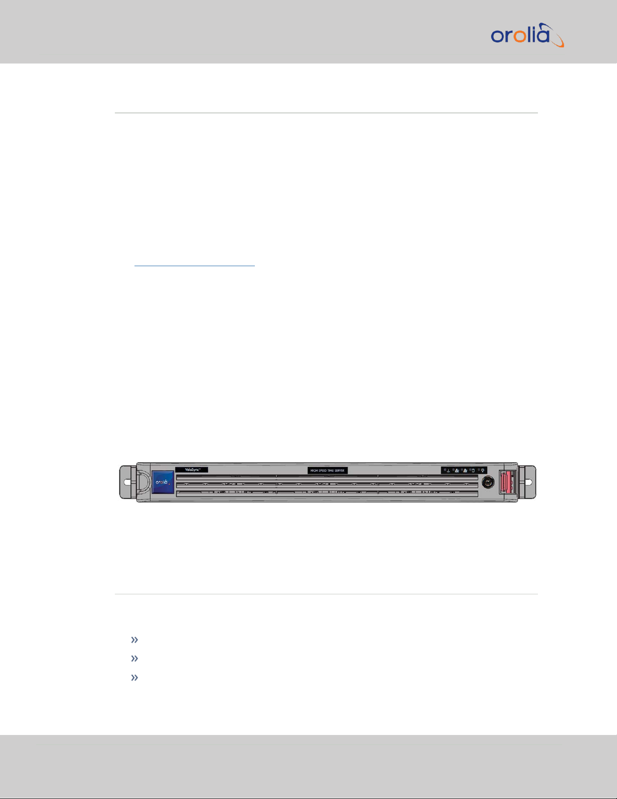
VelaSync® 1232 High-Speed Time Server is an enterprise-class time serving appliance
designed for high-frequency trading and other network applications that require low
latencies.
VelaSync’s customized configuration, comprising state- of- the- art network synchronization software, precision GNSS (GPS) timing technology, and reliable server hardware allows it to provide high-performance time management over multiple network
interfaces.
VelaSync 1232 (part number 1232-xxxx-xxxx) is the latest version of this unit. For
the user manual for an original VelaSync 1225 (part number 1225-xxxx-xxxx) see
the VelaSync User's Manual, archived on the Spectacom website.
Hardware
The customized Supermicro® server platform is a 1U server comprised of a standard
chassis and motherboard, as well as a GNSSreceiver plus oscillator (OCXO, or Rubidium), two hard disks (RAID), two power supplies, and several time, frequency, and communication ports.
Software
The pre-installed Spectracom time synchronization and management software allows
to distribute very accurate time throughout a network, supporting NTP and PTP protocols. In day-to-day operation, the software allows system administrators to centrally
monitor time synchronization accuracy throughout the network in an efficient manner.
Figure 1-1: VelaSync High Speed Time Server
1.2 About this Manual
This User Manual for the VelaSync High-Speed Enterprise Time Server provides you
with:
descriptions of features and functions, as well as
installation and configuration guidance
instructions for specific tasks related to using this product
2
CHAPTER 1 • VelaSync User's Manual Rev. 3
Page 15
1.2 About this Manual
safety-related information
technical specifications
other reference information.
The main objectives of this User Manual are:
a.
to assist you with the installation and configuration of this product in a safe and
efficient manner
b.
to help you familiarize yourself with VelaSync’s user interfaces, features and functionality.
This User Manual is written for a professional audience, targeting experienced system
integrators and PC technicians.
Other relevant documentation
Note: VelaSync 1232, is the latest version of this unit. For the user
manual for an original VelaSync 1225, see the VelaSync User's Manual,
part number 1225-5000-0050, archived on the Spectacom website.
This Spectracom User Manual is complemented by the Spectracom VelaSync Quick
Reference Guide (PN: 1232-5000-0051), a printed copy of which is shipped with the
unit, and the user documentation for the Supermicro™ SuperO® SuperServer 5018RWR, which can be found under:
https://www.supermicro.com/manuals/superserver/1U/MNL-1771.pdf
Manual Organization
This User Manual is organized as follows:
CHAPTER 1: Introduction and Overview
This chapter describes the main features of VelaSync, its hardware operating elements,
and status indicators. Furthermore, the introductory chapter also includes VelaSync's
technical specifications, and regulatory information.
CHAPTER 2: Installation
This chapter describes the preparatory measures, as well as the actual steps necessary
to install VelaSync in a server rack. Also included are SAFETY notes, and typical configuration steps required prior to, or after initial powering on the system.
CHAPTER 1 • VelaSync User's Manual Rev. 3
3
Page 16

1.3 Designated Use of this Product
CHAPTER 3: Managing Time
The software running on VelaSync not only serves time during normal operation, but
also represents the main user interface for configuring and monitoring VelaSync.
CHAPTER3 guides you through the web user interface, WebUI, explaining its features
and functions.
CHAPTER 4: System Administration
Frequently executed tasks are described in CHAPTER4, broken down into the categories, including, "Hardware Tasks" on page163, "Notifications" on page166 , and
"Managing Users and Security" on page175.
APPENDIX
The document appendix includes "Troubleshooting" on page208, as well as admin-
istrative information, how to contact Spectracom Support, and license notices.
1.3 Designated Use of this Product
This product has been designed and built in accordance with state-of-the-art standards
and the recognized safety rules. Nevertheless, its use may constitute a risk to the operator or installation/maintenance personnel if used under conditions that must be
deemed unsafe, or for purposes other than the product's designated use.
The VelaSync High-Speed Enterprise Time Server is intended for use in restricted
access areas. A restricted access area can be accessed only through the use of a special
tool, lock and key, or other means of security.
Installation and maintenance of this device should be performed by experienced technicians only.
For additional information on how and where to use this product, see also "Selecting
the Right Installation Location" on page24 and "YOUR SAFETY" on page17.
4
CHAPTER 1 • VelaSync User's Manual Rev. 3
Page 17

1.4 Technical Specifications
1.4.1 Hardware
1.4.1.1 Server
Supermicro SuperServer 5018R- WR rackmount server with 1U chassis and
X10SRW-F motherboard:
Four 8cm counter-rotating PWM fans
One passive CPU heatsink
Two riser cards
Four hot-swap 3.5" drive bays (SATA)
Intel 1.8 GHz Quad-Core Xeon Processor
1.4 Technical Specifications
8 GB RAM
Two Western Digital Re 1 TB Enterprise-Class Hard Drives in RAID Mirroring configuration
Two redundant, hot-swap power supplies, 100-240 VAC auto-switch, 50-60 Hz,
500W each, with IEC60320 C14 inlet coupler
Connectivity:
I/O connectors: See "Rear Panel Overview" on page12.
1.4.1.2 GPS/GNSS Receiver
Connector: SMA, +5V to power active antenna (SMA-to-Type-N-adapter cable
included)
Frequency: GNSS L1 (1575.42 MHz)
Satellite tracking: 1 to 50, T-RAIM satellite error management
Synchronization time:
Cold start < 15 minutes (includes almanac download)
Warm start < 5 minutes (assumes current almanac downloaded)
GNSS Antenna system: See antenna installation guide (antenna sold separately)
CHAPTER 1 • VelaSync User's Manual Rev. 3
5
Page 18
OCXO Rb
Accuracy to UTC
(1 sigma locked to
GPS)
50 ns 25 ns
Holdover Accuracy
(loss of GPS signal after 2 weeks locked, constant temperature)
After 4 hours 1μs 0.2 μs
After 24 hours 25 μs 1μs
1.4 Technical Specifications
1.4.1.3 Oscillator
Table 1-1:
Oscillator accuracies
Notes:
• Accuracy to UTC is measured by comparing the internal 1PPS with the GPS ontime point.
• When ordering a VelaSync unit, either an OCXO or Rubidium oscillator must be specified.
• The specifications are subject to a steady environment temperature.
1.4.2 I/O Connectors
1.4.2.1 Timing Connector
The pre-installed TSync-model 25-pin Micro D-Sub Connector, when combined with the
adaptor cable and breakout cable (both included), provides the following I/O options:
6
Inputs:
1 PPS Input
1 Hz pulse, rising edge or falling edge active (selectable); 100 ns minimum
pulse width
Amplitude: 0V to +5.5V input range, +0.8V
Input impedance: <150 pF capacitive
IRIG AM Input
Accepts IRIG formats A, B, G; NASA36; IEEE 1344
Amplitude: 500mV
Modulation ratio: 2:1minimum, 6:1maximum
Input impedance: 10 kΩ minimum
DC Common Mode Voltage: ±150VDC maximum
Input Stability: Better than 100 ppm
p-p
to 10V
p-p
CHAPTER 1 • VelaSync User's Manual Rev. 3
, +2.0V
VIL
VIH
Page 19
IRIG DCLS Input
TCXO OCXO
OCXO (Rugged
Option, cPCI & VPX
only)
Accuracy to UTC
(1-
sigma locked to GPS)
±50 ns±50 ns±25 ns
Accepts IRIG formats A, B, G; NASA36; IEEE 1344 pulse width codes (does
not accept Manchester modulated codes)
RS-485 differential input: –7V to +12V common mode voltage input range,
200mV
p-p
Single-ended input:
1.4 Technical Specifications
differential voltage threshold
GPIO Inputs
Outputs
1 PPS Outputs
+1.3V
VIL min
+1.45V
Amplitude: 0V to +5.5V input range, +0.8V
VIL typ
, +2V
, +1.85V
VIH max
VIH typ
, +2.0V
VIL
VIH
Polarity (selectable): Positive or negative
Input impedance: <150pF capacitive
50ns active pulse width minimum; 50ns minimum between pulses
Repetition rate. More than 10,000 events per second
Resolution: 5 ns
1Hz pulse, rising edge or falling edge active (selectable)
40 ns to 900 ms active pulse width (selectable, 200 ms default)
Rise time: <10 ns
Signal level: TTL compatible, 4.3V
, base-to-peak into 50Ω
min
[PCIe only: TTL compatible, 2.2 V minimum, base-to-peak into high impedance]
CHAPTER 1 • VelaSync User's Manual Rev. 3
Accuracy: Positive edge within ±[X] nanoseconds of UTC when locked to a
valid 1PPS input reference (for [X], see table below).
Table 1-2:
1 PPS output accuracy
7
Page 20
TCXO OCXO
OCXO (Rugged
Option, cPCI & VPX
only)
Holdover
(constant temp after 2 weeks of GNSS lock)
After 4 hours 12 μs 3 μs 1 μs
After 24 hours 450 μs100 μs 25 μs
1.4 Technical Specifications
10 MHz Output
10 MHz sine wave output from oscillator
Output impedance: 50 Ω nominal
Output load: 50 Ω minimum
Output harmonics: < -40 dBc
Output spurious: < -70 dBc
IRIG AM Output
Output formats A, B, E (100Hz, 1kHz), G; NASA36; IEEE 1344
Amplitude:
0.5V
1V
p-p
Output impedance: 50 Ω nominal
Output load: 50 Ω minimum
Modulation ratio: 3:1 nominal
Accuracy: ±2 to 200 microseconds (IRIG-format dependent)
IRIG DCLS Output
Outputs formats: A, B, E, G; NASA36; IEEE 1344 pulse width codes (does
not generate Manchester modulated codes)
RS-485 differential signal:
1.8V
1.5V
Single-ended amplitude (100 Ω load):
to 6V
p-p
to 12V
common mode output voltage (RS-485 compatible)
max
to 3.3V max differential output voltage swing
min
into 50 Ω, user settable
p-p
into > 600 Ω
p-p
GPIO Outputs
Periodic Output:
8
0.5V
max, +2.5 V
VOL
min (TTL compatible)
VOH
CHAPTER 1 • VelaSync User's Manual Rev. 3
Page 21

1.4 Technical Specifications
Amplitude: TTL compatible, 4.3V
[PCIe only: 2.2 V minimum, base-top-peak into high impedance]
Pulse width: 50ns to 999ms active pulse width, in 20ns increments
Period: 100ns min, 60s max, in 20ns increments
Polarity (selectable): Positive or negative
Time-Match/Alarm Output
Amplitude: TTL compatible, 4.3 V minimum, base-to-peak into 50 Ω; 2.2 V
minimum, base-to-peak into high-impedance
Range: 100 days in 5 ns steps
1.4.2.2 Communication Ports
2x 10 GbE SFP+ (optionally 4x, or 2x 10Gb plus 2x 40Gb1)
2x 1GbE RJ-45 with hardware time stamping
1x IPMI (V.2.0)
1x RS-232 (Fast UART)
4x USB 2.0
, base-to-peak into 50Ω
min
1x VGA
1.4.3 Environmental Specifications
Operation: 10°C to 35°C, RH: 8 to 90% (non-condensing @ 35°C)
Storage: –40°C to +50°C , RH: 5 to 95% (non-condensing @ 35°C)
1.4.4 Size, Weight & Power
Dimensions: (WxHxD) 437 x 43 x 650 mm (17.2 x 1.7 x 25.6 in.)
Weight: 23.5 lbs. (10.7 kg)
AC input: 100 - 240V
For additional hardware specifications, see the User's Manual of the Original Equipment
Manufacturer:
https://www.supermicro.com/manuals/superserver/1U/MNL-1771.pdf
, 50 - 60 Hz, 6.1 - 2.6 A
RMS
1
Please inquire about availability.
CHAPTER 1 • VelaSync User's Manual Rev. 3
9
Page 22
1.5 Front Panel Overview
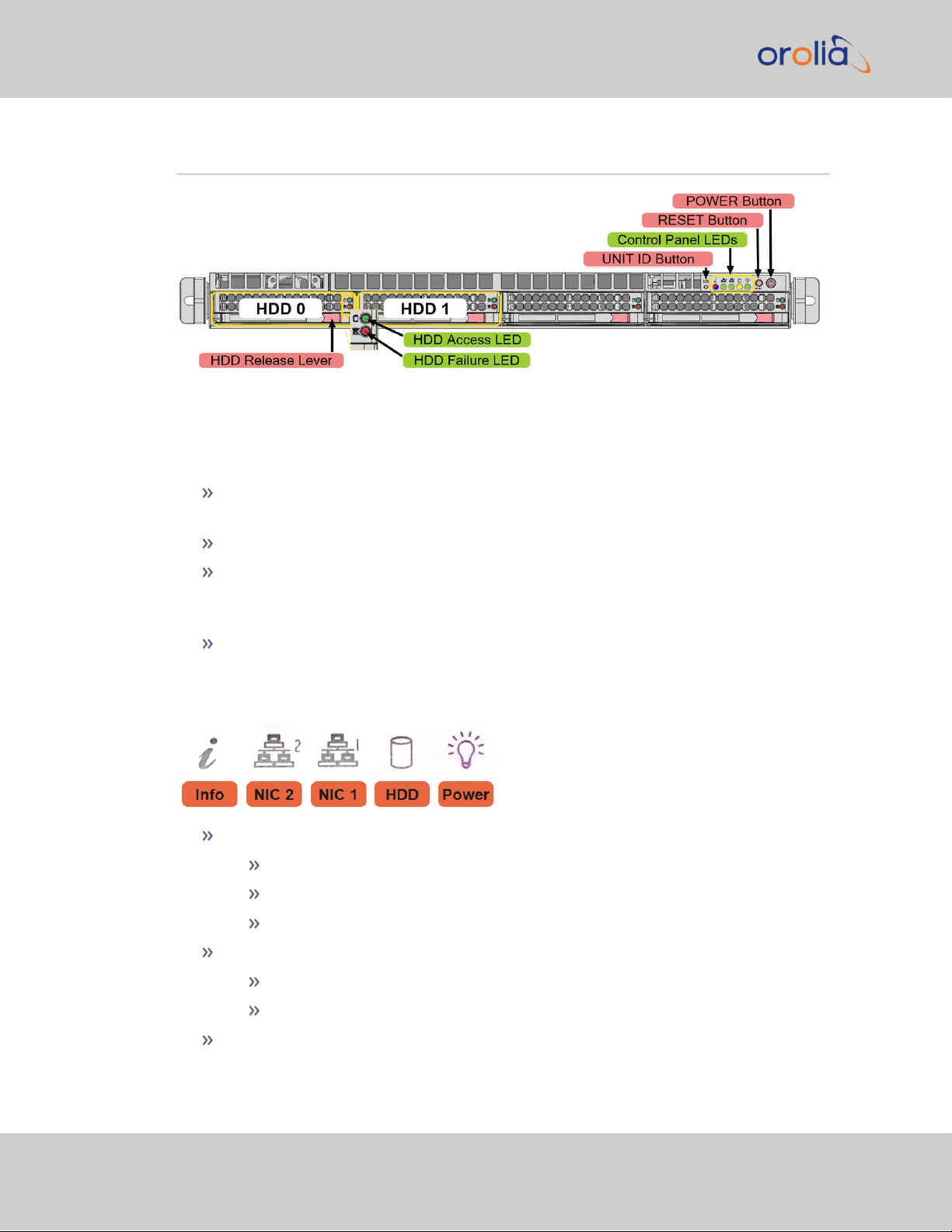
1.5 Front Panel Overview
Figure 1-2: Front Panel (bezel removed)
1.5.1 Control Buttons
UNIT ID ("UID"): Unit identifier button – to identify this unit, press this button (or
activate via IPMI) to turn the blue "i" LED in front and back of unit on/off.
RESET button: Reboot the system
Power button: Apply/remove power from the power supply of the server. (Note:
Standby power continues to be supplied to the system, i.e. the power supplies
and the IPMI remain energized)
HDD Release Lever: Pull to release one of the two hot-swap RAID hard disks.
1.5.2 Control Panel LEDs
Info (red):
Red blinking fast (1x/sec): Fan fail
Red blinking slowly (1x/4 sec): Power fail
Red solid: CPU overheat
Info (blue):
Blue solid: Local UID button depressed
10
Blue blinking: UID has been activated via IPMI
NIC 2, 1: Activity on GLAN 1,2 when flashing green
CHAPTER 1 • VelaSync User's Manual Rev. 3
Page 23

HDD: IDE channel activity when flashing yellow
Power: Power is applied to power supplies (bright green)
1.5.3 Hard Disk Drives
Each hard disk drive (HDD) carrier has two LEDs:
Green LED: Indicates drive activity, when illuminated.
Red LED:
When blinking, the drive is rebuilding.
When solid, indicates drive failure (you should also receive an automatic
message from your system management software).
To release a hard disk drive carrier, in order to remove the hot-swappable hard disk
drive, push the red button for the carrier to release the lever, then pull the carrier out,
using the lever.
For additional instructions on how to replace a hard disk, see "Removing/Installing a
Hard Disk Drive" on page164.
1.5 Front Panel Overview
CHAPTER 1 • VelaSync User's Manual Rev. 3
11
Page 24

1.6 Rear Panel Overview
1.6 Rear Panel Overview
Figure 1-3: VelaSync rear panel
Legend:
1./2.: 1GbE ports (RJ-45)
3./4.: 10 GbE ports (SFP+)
5./6.: Optional 10 GbE ports (SFP+), or 40 GbE (QSFP+)
1
7.: GPS/GNSS antenna connector (SMB)
8.: VGA
9.: Spectacom TSync timing connector 2 Includes rear status LED's ("Status LEDs" on
page42).
10.: USB (4x)
11.: IPMI
12.: Serial
13./14.: Power supplies
Note: VelaSync does not support having multiple network interfaces
on the same subnet or multipath routing.
12
1
Please inquire about availability.
2
- PPS Output is 3.3V and should be terminated to 50 Ohms.
CHAPTER 1 • VelaSync User's Manual Rev. 3
Page 25
1.7 The VelaSync Web UI
VelaSync has an integrated web user interface (referred to as "WebUI" throughout
this documentation) that can be accessed from a network-connected computer, using a
standard web browser. The WebUI is used to configure and monitor the unit.
Note: An integrated Command-Line Interpreter interface (CLI) allows
the use of a subset of commands that are integrated into the Web UI.
The minimum browser requirements for the Web UI are: Internet Explorer®9 or
higher, Firefox®, or Chrome®.
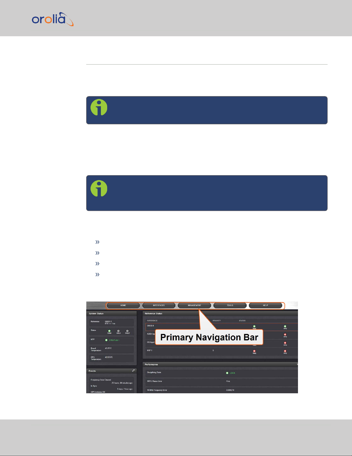
1.7.1 The Web UI HOME Screen
Note: Screens displayed in this manual are for illustrative purposes.
Actual screens may vary depending upon the configuration of your
product.
1.7 The VelaSync Web UI
The HOME screen of the VelaSync web user interface ("Web UI") provides comprehensive status information at a glance, including:
vital system information
current status of the references
key performance/accuracy data
major log events.
The HOME screen can be accessed from anywhere in the Web UI, using the
HOMEbutton in the Primary Navigation Bar:
CHAPTER 1 • VelaSync User's Manual Rev. 3
13
Page 26
1.7 The VelaSync Web UI
The Primary Navigation Bar provides access to all menus:
HOME: Return to the HOME screen (see above)
INTERFACES: Access the configuration pages for …
MANAGEMENT: Access the NETWORK setup screens, and OTHER setup
screens e.g., to configure Reference Priorities, System Time, and the Oscillator.
TOOLS: Opens a drop-down menu for access to the system maintenance
screens and system logs.
HELP: Provides Spectracom Service Contact Information and high-level system
configurations you may be required to furnish when contacting Spectracom Service.
… references (e.g., GNSS, NTP)
… outputs (e.g. 10 MHz, PPS, NTP) and
… installed input/output option cards.
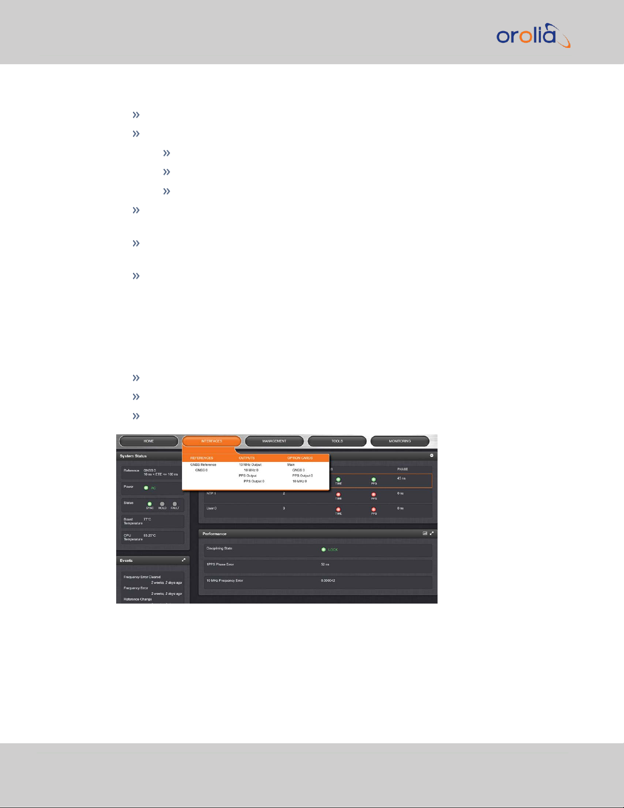
1.7.2 The INTERFACES Menu
The INTERFACES menu on the Main screen provides access to VelaSync's:
External REFERENCES e.g., the GNSS reference input
Detected OUTPUTS, such as 10 MHz and 1PPS
Installed OPTIONS.
Clicking on any of the line items will open a status screen, providing real-time information on the selected interface e.g., availability, performance data and events history.
14
To configure settings for the selected interface, click the GEAR icons or buttons
provided on most of the status screens. Icons like the INFO symbol provide access to
more detailed status information and history data.
CHAPTER 1 • VelaSync User's Manual Rev. 3
Page 27

The headings of each of the INTERFACES drop-down menus (white on orange) open
overview status screens for the respective menu items.
1.7.3 The Configuration MANAGEMENT Menu
The MANAGEMENT menu on the Web UI's Main screen provides access to VelaSync's
configuration screens and settings.
On the left side, under NETWORK, the following standard setup screens can be found:
Network Setup
SSH Setup
SNMP Setup
NTP Setup
PTP Setup
Under OTHER, you can access non-network related screens:
Authentication: Manage user accounts, Security Policy, LDAP Setup, RADIUS
setup, Login Preference and Remote Servers. Change My Password is also available.
1.7 The VelaSync Web UI
Reference Priority: Define the order of priority for timing inputs.
Notifications: Configure the notifications triggered by VelaSync’s events. A noti-
fication can be a combination of a mask alarm and/or SNMP Trap and/or email.
Time Management: Manage the Local Clock, UTC Offset, DST Definition and
Leap Second information.
System Time Message: Configure a regularly delivered message of the system
time.
Log Configuration: Manage the system logs.
Disciplining: Manage oscillator disciplining.
Change My Password: Configure the admin password.
1.7.4 The TOOLS Menu
The TOOLS menu on the Web UI's Main screen provides access to:
The System Upgrade screen
System and network monitoring screens
Miscellaneous system administration screens
Log screens
CHAPTER 1 • VelaSync User's Manual Rev. 3
15
Page 28

1.7 The VelaSync Web UI
16
CHAPTER 1 • VelaSync User's Manual Rev. 3
Page 29
1.8 YOUR SAFETY
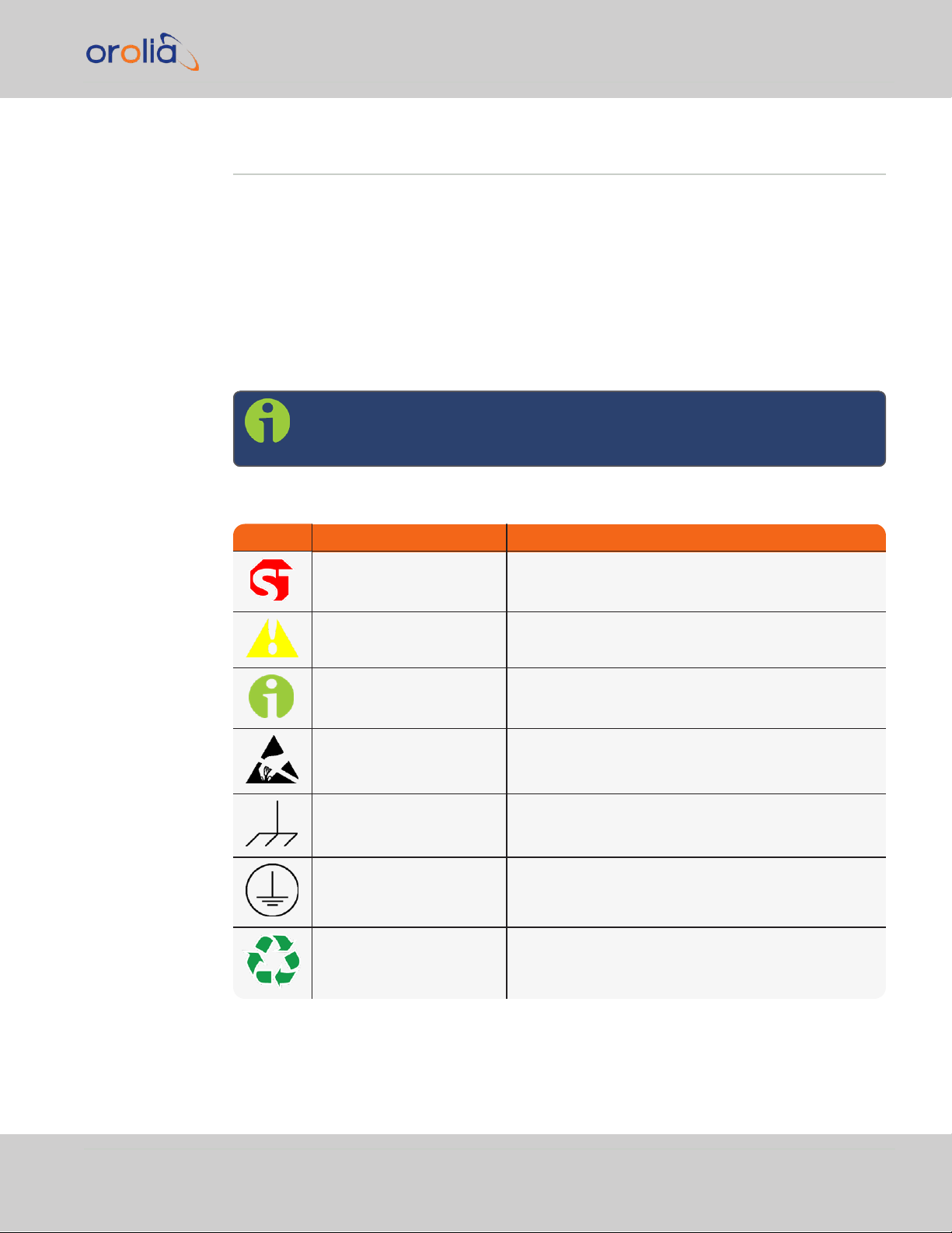
Symbol Signal word Definition
DANGER!
Potentially dangerous situation which may lead to personal injury or death! Follow the instructions closely.
CAUTION!
Potential equipment damage or destruction!
Follow the instructions closely.
NOTE
Tips and other useful or important information.
ESD
Risk of Electrostatic Discharge!
Avoid potential equipment damage by following ESD
Best Practices.
CHASSIS GROUND
This symbol is used for identifying the functional
ground of an I/O signal. It is always connected to the
instrument chassis.
Analog Ground
Shows where the protective ground terminal is connected inside the instrument. Never remove or loosen
this screw!
Recycle
Recycle the mentioned components at their end of life.
Follow local laws.
This product has been designed and built in accordance with state-of-the-art standards
and the recognized safety rules. Nevertheless, its use may constitute a risk to installation/maintenance personnel if used under conditions that must be deemed unsafe, or
if the warnings and precautions explained below are ignored.
Additional Safety Notes pertaining to hardware installation can be found under "Rack
Mounting: SAFETY" on page25.
1.8.1 SAFETY: Symbols Used
Note: The following symbols may be found in Spectracom technical
documentation, or on Spectracom products:
1.8 YOUR SAFETY
Table 1-3:
Spectracom safety symbols
CHAPTER 1 • VelaSync User's Manual Rev. 3
17
Page 30
1.8 YOUR SAFETY
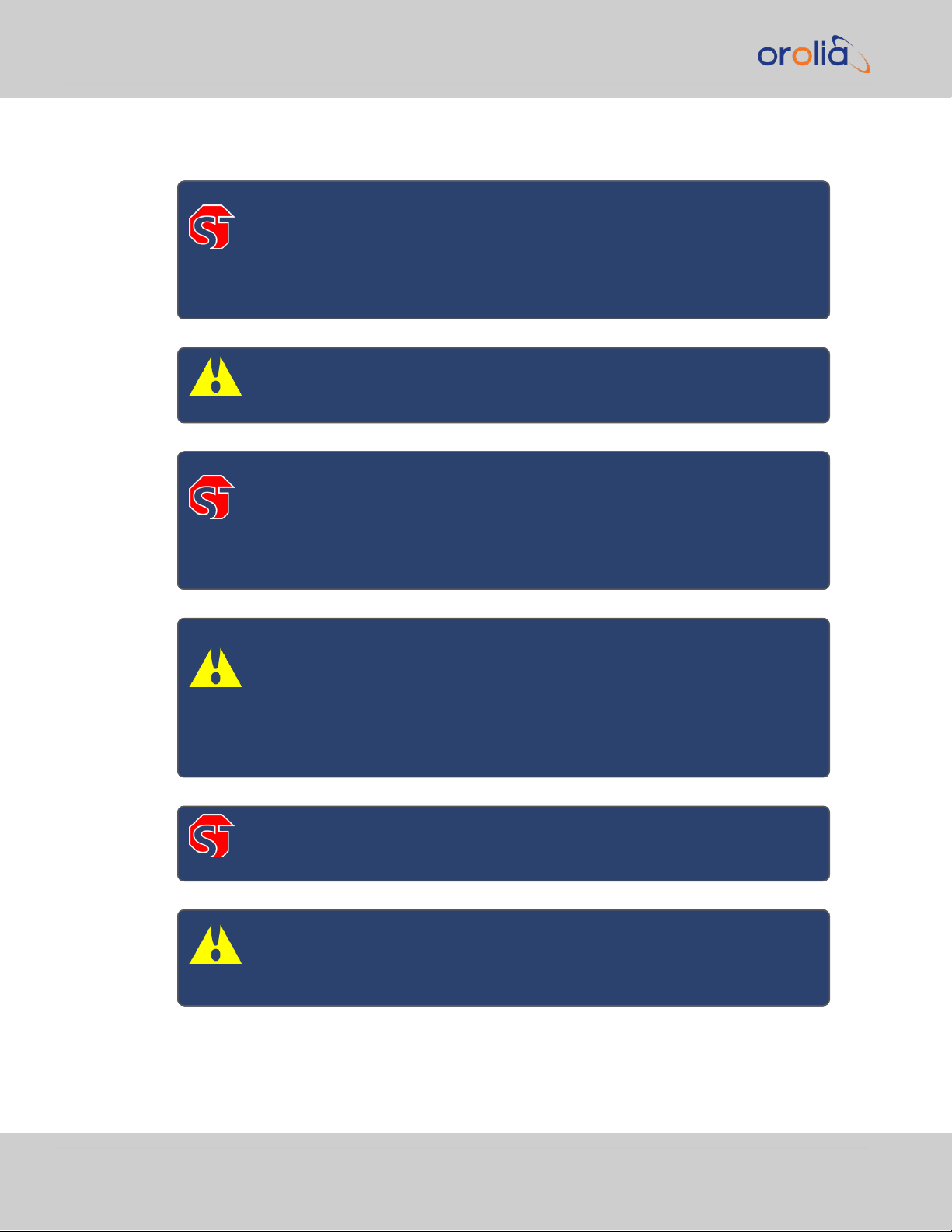
1.8.2 SAFETY Advisories
DANGER! ELECTRICAL HAZARD — DO NOT OPEN THE ENCLOSURE:
No user-serviceable parts inside (the product warranty will be voided,
if the Seal is broken). Should you ever decide to open the enclosure at
your own risk, unplug and remove BOTH power supplies first (the
POWER button will NOT de-energize the system!).
Caution: Only trained and qualified personnel should be allowed to
install, replace, or service this equipment.
DANGER! — GROUNDING: A reliable ground must be maintained at all
times. To ensure this, the rack itself should be grounded. Particular
attention should be given to power supply connections other than the
direct connections to the branch circuit (i.e. the use of powerstrips,
etc.).
Caution: CIRCUIT OVERLOADING — Consideration should be given to
the connection of the equipment to the power supply circuitry and the
effect that any possible overloading of circuits might have on overcurrent protection and power supply wiring. Appropriate consideration
of equipment nameplate ratings should be used when addressing this
concern.
DANGER! Hazardous voltage or energy is present on the back panel
when the system is operating. Use caution when servicing.
Caution: Do not use power supplies other than the p/s model installed
in your VelaSync™, and do not mix power supplies with different
power ratings.
NOTE: Replacement power supplies can be purchased directly from Spectracom (Part no. PS09R-
070J-SL01).
18
CHAPTER 1 • VelaSync User's Manual Rev. 3
Page 31

1.8 YOUR SAFETY
Please be sure to also consult local and national electrical codes, and the User's Manual
of the Original Equipment Manufacturer which can be accessed online under:
https://www.supermicro.com/manuals/superserver/1U/MNL-1771.pdf.
Ultimate disposal of this product should be handled according to all national laws and regulations.
SAFETY: General Advice
Make sure you possess the professional skills, and have received the training
necessary for the type of work you are about to perform.
The equipment must only be used in technically perfect condition. Check components for damage prior to installation. Also check for loose or scorched cables
on other nearby equipment.
Do not modify the equipment.
Use only spare parts authorized by Spectracom.
SAFETY: Hands-On Advice
Before working with or on the equipment, familiarize yourself with the location of
the ON/OFF switch on the unit, the closest disconnection switch in the room,
and electrical outlet, so that you can quickly remove power from the unit in the
event of an emergency.
Do not work alone. The other person should also know how to disconnect power
to the unit you are working on.
Always remove power from the unit, before working on it. Before disconnecting
power, gracefully shut down the unit.
Should you ever have to work on powered on electrical equipment, use only one
hand, in order to avoid making a complete circuit.
To protect yourself from electrical shock, use rubber mats specifically designed
as electrical insulators (not ESD mats).
Keep these instructions at hand, near the place of use.
Keep your workplace tidy.
Do not wear loose clothing.
Remove any metal objects, such as jewelry, from your body.
Apply technical common sense: If you suspect that it is unsafe to use the product,
do the following:
CHAPTER 1 • VelaSync User's Manual Rev. 3
19
Page 32

1.9 Regulatory Compliance
ESD: Best Practices
This product does not require opening. In the event that an internal component failed
(e.g., a fan), contact Spectracom service (see "Technical Support" on page240).
Disconnect the supply voltage from the unit.
Clearly mark the equipment to prevent its further operation.
DANGER! — ELECTRICAL HAZARD — DO NOT OPEN THE
ENCLOSURE: No user-serviceable parts inside. Should you ever decide
to open the enclosure at your own risk, unplug and remove BOTH
power supplies first (the POWER button will NOT de-energize the system!)
Caution: Electronic equipment is sensitive to Electrostatic Discharge
(ESD). Observe all ESD precautions and safeguards when handling Spectracom equipment.
Use a grounded wrist strap to prevent static discharge.
Put components and PCBs back into their antistatic bags, while not in use.
Touch a grounded metal object before removing a PCB from its antistatic bag.
Make sure the unit's chassis, its power supply, and main components are electrically connected to one another, so as to allow reliable grounding.
Do not let components or PCBs come into contact with your clothing.
Handle PCBs on their edges only; avoid touching electronic components or contacts. If you have to handle a chip, avoid touching its pins.
1.9 Regulatory Compliance
This product has been found to be in conformance with the following regulatory publications.
FCC
This equipment has been tested and found to comply with the limits for a ClassA
digital device, pursuant to Part15 of the FCC Rules.
20
CHAPTER 1 • VelaSync User's Manual Rev. 3
Page 33

1.9 Regulatory Compliance
These limits are designed to provide reasonable protection against harmful inter-
ference when the equipment is operated in a commercial environment. This equip-
ment generates, uses, and can radiate radio frequency energy and, if not installed and
used in accordance with the user documentation, may cause harmful interference to
radio communications.
Operation of this equipment in a residential area is likely to cause harmful inter-
ference in which case the user will be required to correct the interference at his/her
own expense.
Note: This is a Class A product. In a domestic environment this product
may cause radio interference in which case the user may be required
to take adequate measures.
Safety
This product has been tested and meets the requirements specified in:
IEC/EN/UL/CSA 62368-1:2014
EMC Compliance
This product has been tested and meets the following standards:
EN 55032:2012/AC:2013/CISPR 32:2012: Class A
ICES-003 Issue 6: Class A
FCC CFR 47 PART 15 SubPart B:2016: Class A
EN55024:2010: Class A
EN 61000-3-2:2014
EN 61000-3-3:2013
AS/NZS CISPR 32:2015
Radio Spectrum Efficiency:EN 303 413 V1.1.1
European Directives
This product has been tested and complies with the following:
2014/30/EU Electromagnetic Compatibility (EMC)
2014/35/EU Low Voltage (LVD)
2011/65/EU on the Restriction of Hazardous Substance (RoHS2)
2014/53/EU Radio Equipment Directive (RED)
CHAPTER 1 • VelaSync User's Manual Rev. 3
21
Page 34

1.9 Regulatory Compliance
BLANK PAGE.
22
CHAPTER 1 • VelaSync User's Manual Rev. 3
Page 35

Installation & Setup
The following topics are included in this Chapter:
2.1 Unpacking and Inventory 24
2.2 Selecting the Right Installation Location 24
2.3 Rack Mounting: SAFETY 25
2.4 Rack Installation 26
2.5 Basic Connections Setup 29
2.6 Accessing the WebUI 31
2.7 Configuring IP Address(es) 32
2.8 Advanced Timing Connections 35
2.9 Configuring Network Settings 43
2.10 Configuring NTP 68
2.11 Configuring PTP 86
CHAPTER 2
CHAPTER 2 • VelaSync User's Manual
23
Page 36

2.1 Unpacking and Inventory
2.1 Unpacking and Inventory
Caution: Electronic equipment is sensitive to Electrostatic Discharge
(ESD). Observe all ESD precautions and safeguards when handling the
unit.
Unpack the equipment and inspect it for damage. If any components have been damaged in transit, you should file a damage claim with the with the carrier who delivered
the unit.
Should you experience any problems during installation and configuration of your Spectracom product, please contact your closest Spectracom Customer Service Center
(see "Technical Support" on page240).
Note: Retain all original packaging for use in return shipments, if neces-
sary.
What's in the box?
VelaSync unit
Two (2) sets of rail assemblies
Two (2) rail mounting brackets, extension elements, and mounting hardware
Front bezel, and keys
Two (2) power cables
Spectracom Ancillary Kit, containing one (1) antenna cable, one (1) TSync standard
breakout cable, and one (1) timing I/O adaptor cable.
Optional equipment e.g., GPS antenna and surge suppressor
Documentation: VelaSync Quickstart Guide, Supermicro documentation, Mellanox documentation.
After inspecting the contents of the shipment, continue with Chapter "Selecting the
Right Installation Location" below.
2.2 Selecting the Right Installation Location
VelaSync has been designed to be installed in an industry-grade, slide-mount 19" server
rack or cabinet. Note that VelaSync is not suitable for use with a visual display work
place device (§2 of the German Ordinance for Work with Visual Display Units).
24
CHAPTER 2 • VelaSync User's Manual Rev. 3
Page 37

2.3 Rack Mounting: SAFETY
Select a suitable location that meets the following requirements:
A dedicated room with restricted access
Electrically grounded and mechanically stable rack, with physical clearance
for unrestricted air flow and servicing: approx. 650 mm [25”] in front of rack, 770
mm [30”] in the back of rack
Clean, dust-free, and stable1 ambient temperature not to exceed 35°C [95°F].
Virtually free of EMC noise
Access to a reliable grounded power outlet
Sufficiently dimensioned power supply circuitry, to prevent overloading of cir-
cuits.
The use of a regulating UPS (Uninterruptible Power Supply) is recommended.
Next Steps:
Read "YOUR SAFETY" on page17, and "Rack Mounting: SAFETY" below before
familiarizing yourself with the procedure for the "Rack Installation" on the next
page.
2.3 Rack Mounting: SAFETY
Read "YOUR SAFETY" on page17.
Before installing VelaSync in the fully extended rails, or before extending the unit
from the rack, ensure that the rack is stable enough to support the weight of the
fully extended unit. If you are using a standalone rack, it may be necessary to
install stabilizers to the rack.
Always extend only one unit at a time.
Install heavier servers near the bottom of the rack.
The unit weighs approximately 24 lbs (11 kg). Depending on your chosen installation location, it may be advisable to lift the unit with two persons.
1
An environment where a constant temperature can be maintained during operation, to allow for the best pos-
sible timing accuracy.
CHAPTER 2 • VelaSync User's Manual Rev. 3
25
Page 38

2.4 Rack Installation
2.4 Rack Installation
Note: We recommend that you read this Chapter in its entirety before
you begin with the installation.
Note: Also consult the installation instructions that came with the rack
or cabinet you plan on using.
All VelaSync units are shipped with two rack rail assemblies, each of which consists of
two sections:
the inner rail, which is pre-installed to the server chassis
the outer rail assembly, which faces the rack
26
Figure 2-1: Rack rail assembly
Optional inner rail extension elements (shown in red) are provided to accommodate
installation scenarios requiring maximum unit extension from the rack, e.g. for service &
maintenance. Consult your rack manufacturer's user manual for additional information.
CHAPTER 2 • VelaSync User's Manual Rev. 3
Page 39

2.4 Rack Installation
Figure 2-2: Optional inner rails
Installing the outer rail to the rack:
1.
Measure the distance from the front rail to the rear rail of the rack. Attach a
short bracket to the front side of each of the outer rails, and a long bracket to
the rear side of each outer rail.
2.
Adjust both the short, and the long brackets to the proper distance so that the
rails fit snugly into the rack. Secure the short bracket to the front side of the
outer rail with two screws, and the long bracket to the rear side of the outer rail
with three screws.
Installing the server into the rack:
Once all the rails have been installed to the VelaSync chassis and the rack, the VelaSync
unit can be installed into the rack.
Caution: The unit weighs approximately 24 lbs (11 kg). Depending on
your chosen installation location, it may be advisable to lift the unit
with two persons.
3.
Line up the rear of the inner rails at the chassis with the front of the outer rails at
the rack. Slide the server chassis into the rack, keeping the pressure even on
CHAPTER 2 • VelaSync User's Manual Rev. 3
27
Page 40

2.4 Rack Installation
both sides. Depress the locking tabs, if needed (they will click upon proper engagement).
Figure 2-3: Rack installation
2.4.1 TELCO Rack Installation
To install the VelaSync unit in a Telco-type rack, use two L-shaped brackets on either
side of the VelaSync chassis.
1.
Determine how far forward the unit will extend out of the front of the rack.
Determine a balanced front-to-back position of the chassis.
2.
Remove the bezel from the VelaSync. Attach the two front brackets to each side
of the chassis, then the two rear brackets, leaving just enough space to accommodate the width of the telco rack.
3.
Slide the VelaSync into the rack, and tighten the brackets to the rack.
28
CHAPTER 2 • VelaSync User's Manual Rev. 3
Page 41

2.5 Basic Connections Setup
This section is designed to take your through the initial setup steps in order to allow you
to communicate with and configure your VelaSync.
Figure 2-4: VelaSync rear panel
2.5 Basic Connections Setup
2.5.1 Connecting the GPS Antenna
For instructions on how to install a GPS/GNSS antenna, the signal cable, and accessor-
ies such as surge protectors, weatherproofing kits, or amplifiers , refer to the Install-
ation Guide that came with the respective equipment.
For additional information regarding the GPS antenna location selection, see "Choosing
a GNSS Antenna Location" on page235.
1.
Connect the GPS/GNSS antenna to the GNSS RF connector (see illustration
above, item number 7), using the supplied Type-N adapter cable, and an LMR-400
equivalent cable with surge suppressor and active GPS L1 antenna, such as Spectracom model 8230.
Note the GNSS receiver connection provides 5VDC power for the antenna.
2.5.2 Connecting Power
Before connecting power to the unit, make sure that you have read all safety information detailed in section "YOUR SAFETY" on page17.
DANGER! When installing the product, use only the provided or des-
ignated power cables. Using any other cables and adaptors could cause
a malfunction or a fire.
CHAPTER 2 • VelaSync User's Manual Rev. 3
29
Page 42

2.5 Basic Connections Setup
DANGER! This product relies on the building's installation for short-cir-
cuit (overcurrent) protection. Ensure that the protective device is rated
not greater than: 250V, 20 A.
2.
Plug in power to both power supplies (items 13 & 14 "Basic Connections Setup"
on the previous page)..
As soon as at least one of the two power supplies has been connected to the
mains voltage, you may hear fan noise from inside the VelaSync housing.
However, note that the unit is not running yet (check the front indicator lamps:
they will remain dark).
3.
Switch the unit on by pressing the ON/OFF button on the front panel. Wait for
the device to boot up.
Note: If only one power supply is running, and the other one is
inserted all the way, but not plugged in, or defective, VelaSync
will emit a long BEEP, so as to alert you of a problem with the
backup power.
Figure 2-5: ON/OFF button
4.
Once the boot process is completed, only the green POWER status LED should
be lit.
2.5.3 Establishing a Network Connection
5.
You can chose to communicate with your VelaSync upon setup in one of three
ways:
30
CHAPTER 2 • VelaSync User's Manual Rev. 3
Page 43

2.6 Accessing the WebUI
ETH0, using the default static IP address (see step 6),
ETH1-ETH5, using a DHCP network (see step 7),
via the serial port (see "Setting Up an IP Address via the Serial Port" on
page33).
6.
The unit is shipped with one static IP address: ETH0 = 192.168.1.1. To com-
municate with the Web UI using this address, connect a PC with a configured
LAN port via Ethernet cable to the VelaSync server using ETH0.
7.
To connect a device using DHCP, connect to an Ethernet port without a static IP
address (any Ethernet port except ETH0). Find the unit on your network by contacting your network administrator, and log in to the unit's assigned IP address.
8.
Log on to the Web UI (see directions in "Accessing the WebUI" below).
9.
Note: You'll likely want to change the default IP address of the
ETH ports you plan on using. This procedure is described in the
next topic . (You will need an Ethernet cable , or a serial null
modem cable for this.)
For more detailed information on network setup, see the section on "Configuring Net-
work Settings" on page43
2.6 Accessing the WebUI
VelaSync's WebUI is the recommended tool to interact with the device, since it
provides access to nearly all configurable settings, and obtain comprehensive status
information without having to use the Command Line Interpreter (CLI).
You can access the Web UI either by using the manually set static IP address (ETH0 =
192.168.1.1), or by using the DHCP IP address automatically assigned during zero config
setup.
1.
Log into the Web UI as an administrator.
Note: The default login credentials are:
User name = spadmin
Password = admin123
CHAPTER 2 • VelaSync User's Manual Rev. 3
31
Page 44

2.7 Configuring IP Address(es)
Note: For security reasons, please change the default password
immediately; see: "Managing Passwords" on page180.
2.
Upon initial login, you will be asked to register your product. Spectracom recommends to register VelaSync, so as to receive software updates and services
notices.
You can also register your product on the Spectracom website :
register.spectracom.com.
See also "Product Registration" on page237.
2.7 Configuring IP Address(es)
VelaSync's ETH0 network interface port is configured with a unique static IP address:
192.168.1.1. The DHCPis shipped disabled on this port, but can be reinstated below.
The other Ethernet ports default to DHCP; if connected to a DHCP server via ETH1
through ETH5, VelaSync will accept a dynamic IP address.
Once you are connected to the Web UI, you can manually adjust the IP addresses for
each ethernet port, and enable or disable DHCP.
2.7.1 Changing the IP address using an Ethernet connection
1.
In order to manipulate network configurations, open a web browser, using a PC
that is on the same network as the VelaSync.
2.
Navigate to the IP address connected to VelaSync; either the default static
address (ETH0) or the dynamic address assigned by your DHCP.
3.
Log onto the Web UI as an administrator. If not yet updated, use the default password:
Note: The default login credentials are:
User name = spadmin
Password = admin123
4.
In the Web UIHOME screen, select the MANAGEMENT menu> Network Setup.
32
5.
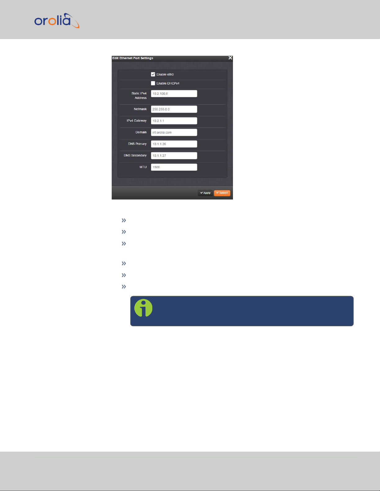
In the Ports panel on the right, click the GEAR button next to the Ethernet port
to be configured: the Edit Ethernet Port Settings panel will open.
CHAPTER 2 • VelaSync User's Manual Rev. 3
Page 45
2.7 Configuring IP Address(es)
6.
In this panel, you can perform the following actions:
enable or disable the ethernet port
enable DHCP
disable DHCP (selecting this function will provide access to the remaining
settings)
assign a static IP address
set netmask values
set Gateway, domain, DNS, and MTU values.
Note: Wait to click Submit or Apply until fully finished
assigning values to avoid errors.
In order to apply a static IP address to any Ethernet port, DHCP must be disabled.
To update network settings using a serial connection, please see "Setting Up an IP
Address via the Serial Port" below.
2.7.2 Setting Up an IP Address via the Serial Port
VelaSync's rear panel serial port connector is a standard DB9 male connector. Communication with the serial port can be performed using a PC with a terminal emulator
program (such as PuTTY or TeraTerm), using a pinned null-modem standard DB9F to
CHAPTER 2 • VelaSync User's Manual Rev. 3
33
Page 46

2.7 Configuring IP Address(es)
DB9M serial cable. The VelaSync serial port operates at 9600 baud, 8 data bits, no parity, 1 stop bit.
The serial port can be used to make configuration changes (such as the network settings), retrieve operational data (e.g., GNSS receiver information) and log files, or to perform operations such as resetting the admin password.
The serial port is account and password protected. You can log in via the serial port
using the same user names and passwords as would be used to log in to the VelaSync
WebUI. Users with administrative permissions can perform all available commands.
Users with user permissions only can perform “get” commands that retrieve data, but
cannot perform any “set” commands or change/reset any passwords.
To configure an IP address via the serial port:
1.
Connect a serial cable to a PC running PuTTY, Tera Term, or HyperTerminal, and
to your VelaSync. For detailed information on the serial port connection, see "Set-
ting up a Terminal Emulator" on page216
2.
Login to VelaSync with a user account that has “admin” group rights, such as the
default spadmin account (the default password is admin123).
3.
Disable DHCP, type: dhcp4set 0 off <Enter>.
Note: For a list of CLI commands, type helpcli , or see
"CLICommands" on page217.
4.
Configure the IP address and subnet mask, type:
ip4set 0 x.x.x.x y.y.y.y <Enter>
(where 0 is the desired interface, “x.x.x.x” is the desired IP address for
VelaSync, and “y.y.y.y” is the full subnet mask for the network (For a list
of subnet mask values, see "Subnet Mask Values" on the facing page.)
5.
Configure the gateway by typing gw4set 0 z.z.z.z<Enter>
(where 0 indicates which interface routing table to add the default gateway for,
and “z.z.z.z” is the default gateway address).
6.
Remove the serial cable, connect VelaSync to the network, and access the Web
UI, using the newly configured IP address. (For assistance, see "Accessing the
WebUI" on page31).
The remainder of the configuration settings will be performed via the Web UI (accessed
via an external workstation with a web browser such as Firefox® or Chrome®).
34
CHAPTER 2 • VelaSync User's Manual Rev. 3
Page 47

2.7.3 Subnet Mask Values
Network Bits Equivalent Netmask Network Bits Equivalent Netmask
30 255.255.255.252 18 255.255.192.0
29 255.255.255.248 17 255.255.128.0
28 255.255.255.240 16 255.255.0.0
27 255.255.255.224 15 255.254.0.0
26 255.255.255.192 14 255.252.0.0
25 255.255.255.128 13 255.248.0.0
24 255.255.255.0 12 255.240.0.0
23 255.255.254.0 11 255.224.0.0
22 255.255.252.0 10 255.192.0.0
21 255.255.248.0 9 255.128.0.0
20 255.255.240.0 8 255.0.0.0
19 255.255.224.0
2.8 Advanced Timing Connections
Table 2-1:
Subnet mask values
2.8 Advanced Timing Connections
Figure 2-6: TSync timing card connections
CHAPTER 2 • VelaSync User's Manual Rev. 3
2.8.1 TSync I/O Signals
The updated VelaSync holds a factory-installed TSync timing card which contains a
GPS/GNSS antenna connection, status LED's,and a 25 pin Micro D-Sub connector.
The Micro D-Sub connector can be expanded into different configurations by use of the
adapter cable and standard breakout cable.
35
Page 48

END "A" END "B"
PIN-1 PIN-1
PIN-2 PIN-2
PIN-3 PIN-3
PIN-4 PIN-4
PIN-5 PIN-5
PIN-6 PIN-6
PIN-7 PIN-7
PIN-8 PIN-8
PIN-9 PIN-9
PIN-10 PIN-10
PIN-11 PIN-11
PIN-12 PIN-12
2.8 Advanced Timing Connections
2.8.1.1 Timing Interface Adapter Cable
VelaSync is shipped with a 15 cm (6") adapter cable that is used to connect the micro
25-pin timing interface connector on the card to the breakout cable:
Figure 2-7: Adapter cable
Table 2-2:
Adapter pinout, timing connector
36
CHAPTER 2 • VelaSync User's Manual Rev. 3
Page 49

END "A" END "B"
PIN-13 PIN-13
PIN-14 PIN-14
PIN-15 PIN-15
PIN-16 PIN-16
PIN-17 PIN-17
PIN-18 PIN-18
PIN-19 PIN-19
PIN-20 PIN-20
PIN-21 PIN-21
PIN-22 PIN-22
PIN-23 PIN-23
PIN-24 PIN-24
PIN-25 PIN-25
NO CONNECT PIN-26 SHIELD
2.8 Advanced Timing Connections
2.8.1.2 Basic Breakout Cable
The basic breakout cable breaks out a subset of features from the 26-pin timing connector to separate BNC and DB-9 connectors for use. The basic breakout cable supports the following features: External 1PPS Input, IRIG AM Input, IRIG DCLS Input, IRIG
AM Output, (1) GP Input, (2) GP Outputs.
CHAPTER 2 • VelaSync User's Manual Rev. 3
37
Page 50

Pin Signal Pin Signal
P1—Timing Connector
3 GPIO Output 0 11 IRIG AM Input –
5 Ground 16 GPIO Output 1-
Reserved
6 GPIO Input 0 18 Ground
7 External 1PPS Input 21 Ground
8 Ground 24 IRIG DCLS Input –
9 IRIG AM Output 25 IRIG DCLS Input +
10 IRIG AM Input +
P2—Digital I/O (DB-9 Female)
1 Ground 6 GPIO Output 0
2 GPIO Input 0 7 Ground
2.8 Advanced Timing Connections
Figure 2-8: Breakout cable, basic version
Table 2-3:
Pinout, basic breakout cable (unspecified pins in the table are not con-
nected)
38
CHAPTER 2 • VelaSync User's Manual Rev. 3
Page 51

Pin Signal Pin Signal
3 Ground 8 GPIO Output 1-
Reserved
4 IRIG DCLS Input + 9 Ground
5 IRIG DCLS Input – BS Ground
P3—IRIG AM Input (BNC Female)
1 IRIG AM Input + BS IRIG AM Input –
P4—IRIG AM Output (BNC Female)
1 IRIG AM Output BS Ground
P5—1PPS Input (BNC Female)
1 External 1PPS Input BS Ground
P6—1PPS Output (BNC Female)
1 1PPS Output BS Ground
2.8 Advanced Timing Connections
2.8.1.3 Premium Breakout Cable
Note: The premium breakout cable must be purchased separately.
Contact Spectracom for details.
The premium breakout cable breaks out all features from the timing connector to separate BNC
and DB-9 connectors for use. See table below for details.
CHAPTER 2 • VelaSync User's Manual Rev. 3
39
Page 52

Pin Signal Pin Signal
P1—Timing Connector
1 GPIO Output 2- Reserved 14 GPIO Output 3- Reserved
2 Ground 15 Ground
3 GPIO Output 0 16 GPIO Output 1- Reserved
4 GPIO Input 2- Reserved 17 GPIO Input 3- Reserved
5 Ground 18 Ground
6 GPIO Input 0 19 GPIO Input 1- Reserved
7 External 1PPS Input 20 1PPS Output
8 Ground 21 Ground
9 IRIG AM Output 22 10 MHz Output
10 IRIG AM Input + 23 Ground
11 IRIG AM Input – 24 IRIG DCLS Input –
12 IRIG DCLS Output – 25 IRIG DCLS Input +
13 IRIG DCLS Output + 26 Shield
2.8 Advanced Timing Connections
Figure 2-9: Breakout cable, premium version
Table 2-4:
Pinout, premium breakout cable (unspecified pins are not connected in the
cable)
40
CHAPTER 2 • VelaSync User's Manual Rev. 3
Page 53

Pin Signal Pin Signal
IRIG DCLS I/O (DB-9 Female)
2 Ground 6 IRIG DCLS Output +
3 Ground 7 IRIG DCLS Output –
4 IRIG DCLS Input + BS Ground
5 IRIG DCLS Input -
P3—10MHz Output (BNC Female)
1 10 MHz Output BS Ground
P4—1PPS Output (BNC Female)
1 1PPS Output BS Ground
P5—IRIG AM Input (BNC Female)
1 IRIG AM Input + BS IRIG AM Input –
P6—IRIG AM Output (BNC Female)
1 IRIG AM Output BS Ground
P7—1PPS Input (BNC Female)
1 External 1PPS Input BS Ground
P8—GP Input (DB-9 Female)
1 GPIO Input 0 7 Ground
2 GPIO Input 1 8 Ground
3 GPIO Input 2 9 Ground
4 GPIO Input 3 BS Ground
6 Ground
P9—GP Output (DB-9 Female)
1 GPIO Output 0 7 Ground
2 GPIO Output 1 8 Ground
3 GPIO Output 2 9 Ground
4 GPIO Output 3
6 Ground BS Ground
2.8 Advanced Timing Connections
CHAPTER 2 • VelaSync User's Manual Rev. 3
41
Page 54

LED Color Function Meaning
green
SYNC Unit is synchronized: A valid external time or
1PPS reference is present, disciplining the
onboard oscillator.
yellow
HOLDOVER Unit is in holdover: No valid external ref-
erence is present. The onboard oscillator is
not disciplined by an external reference, but
continues to provide time/frequency for the
duration of the user-set holdover time
(default = 7200 seconds [= 2 hours]).
red
ALARM The unit does not provide a time or fre-
quency signal.
State
Color/FUNCTION
green/SYNC yellow/HOLDOVER red/ALARM
Power-On On Off Off
Self-Test On On On
Waiting for Host Blink Off Blink
Download from Host Strobe Strobe Strobe
Initialize Off Off Off
Never Synchronized Off Off Off
2.8 Advanced Timing Connections
2.8.2 Status LEDs
VelaSync High-Speed Enterprise Time Server includes a TSync Timing card with three
LEDs that provide visual status information. See table LED Colors below for these indic-
ator codes.
The LEDs operate in certain modes by default.
Table 2-5:
LED colors
During the states power-on, self-test, wait-for-host, and download-from-host,
modes are directly allocated to the LEDs, as listed below.
Table 2-6:
LED flash patterns
42
CHAPTER 2 • VelaSync User's Manual Rev. 3
Page 55

State
Color/FUNCTION
green/SYNC yellow/HOLDOVER red/ALARM
Synchronized On Off Off
Holdover On On Off
No Longer Synchronized Off Off On
Free Run Blink Blink Off
Fault
Code Code Code
No. of Blinks Meaning
1 FPGA programming error
2 Failure to decompress
3 CRC failure writing to flash
4 Self-test failure
5 Timing system failure
2.9 Configuring Network Settings
The Fault state is indicated by the blinking code. It blinks the number of times indicated below,
with a 2-second pause between each set.
Table 2-7:
Fault codes
2.9 Configuring Network Settings
Before configuring the network settings, you need to setup access to VelaSync web
user interface ("Web UI"). For more information, see "Configuring IP Address(es)" on
page32.
Login to the Web UI. For more information, see "Accessing the WebUI" on page31.
To configure network settings, or monitor your network, navigate to VelaSync's Net-
work Setup screen.
To access the Network Setup screen:
Navigate to MANAGEMENT > Network Setup. The Network Setup screen is
divided into three panels:
CHAPTER 2 • VelaSync User's Manual Rev. 3
43
Page 56

2.9 Configuring Network Settings
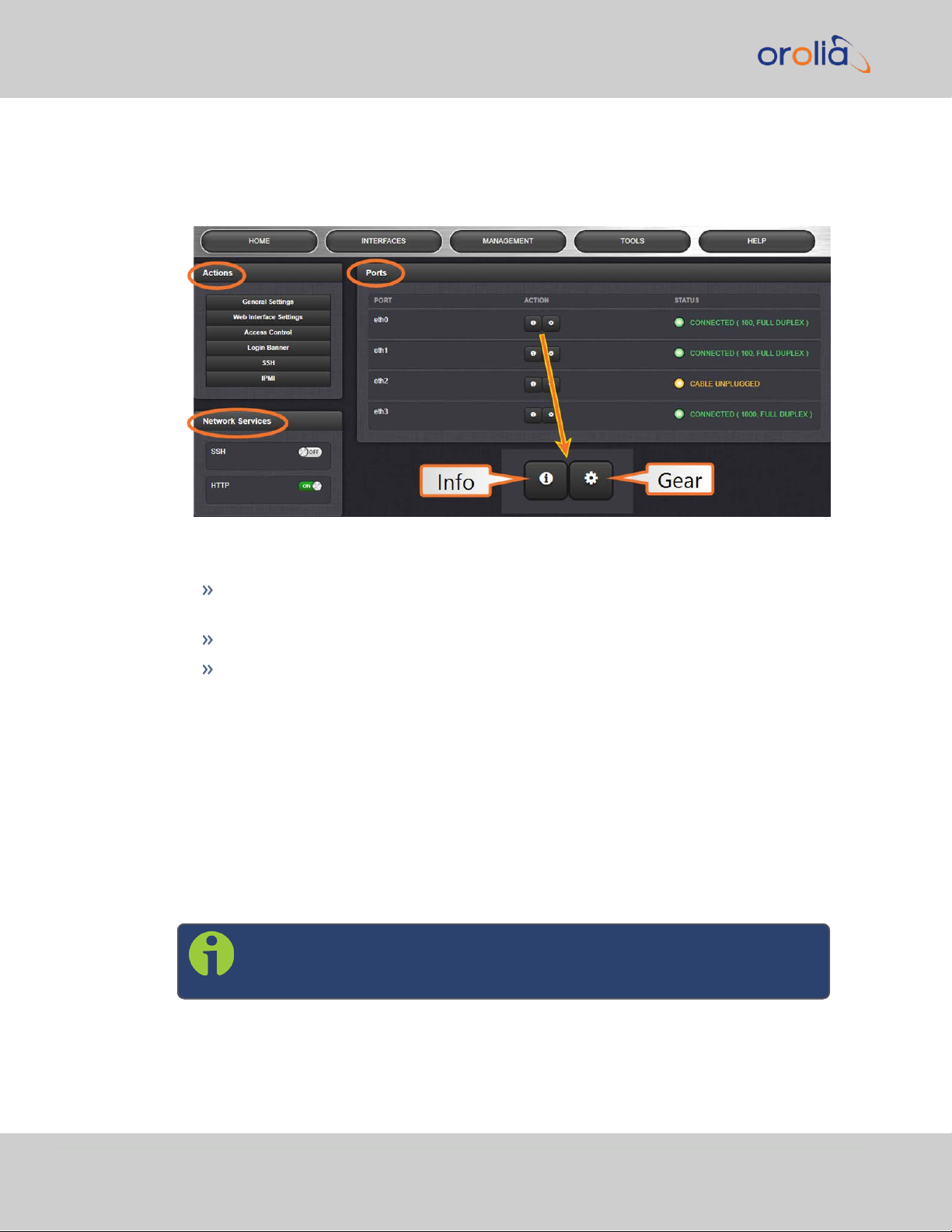
The Actions panel provides:
General Settings: Allows quick access to the primary network settings
necessary to connect VelaSync to a network. See "General Network Set-
tings" on the facing page.
Web Interface Settings:
Web interface timeout: Determines how long a user can stay logged
on. For more information, see "Web UI Timeout" on page184.
Access Control : Allows the configuration of access restrictions from
assigned networks/nodes.
Login Banner: Allows the administrator to configure a custom banner mes-
sage to be displayed on the VelaSync Web UI login page and the CLI (Note:
There is a 2000 character size limit).
SSH: This button takes you to the SSH Setup window. For details on set-
ting up SSH, see "SSH" on page50.
IPMI: Enable/Disable IPMI (ADMIN password required).
The Network Services panel is used to enable (ON) and disable (OFF) network
services, as well as the Web UI display mode, details see: "Network Services" on
page48.
The Ports panel not only displays STATUS information, but is used also to set up
and manage VelaSync’s network ports via two buttons:
INFO button: Displays the Ethernet port Status window for review pur-
poses.
44
GEAR button: Displays the Ethernet port settings window for editing pur-
poses.
CHAPTER 2 • VelaSync User's Manual Rev. 3
Page 57

2.9.1 General Network Settings
To expedite network setup, VelaSync provides the General Settings window, allowing
quick access to the primary network settings.
To access the General Settings window:
1.
Navigate to MANAGEMENT > Network Setup. In the Actions Panel on the left,
click General Settings.
2.9 Configuring Network Settings
2.
Populate the fields:
Hostname: This is the server’s identity on the network or IP address.
Default Port: Unless you specify a specific Port to be used as Default Port,
the factory default port eth0 will be used as the gateway (default gate-
way).
The General Settings window also displays the IPv4 Address and default IPv4
Gateway.
CHAPTER 2 • VelaSync User's Manual Rev. 3
45
Page 58

2.9 Configuring Network Settings
2.9.2 Network Ports
Ports act as communication endpoints in a network. The hardware configuration of your
unit will determine which ports (e.g., Eth0, Eth1, ...) are available for use. Before using a
port, it needs to be enabled and configured.
To enable & configure, or view a network port:
1.
Navigate to MANAGEMENT > NETWORK: Network Setup.
2.
The Ports panel on the right side of the screen lists the available Ethernet ports,
and their connection STATUS:
Green: CONNECTED (showing the connection speed)
Yellow: CABLE UNPLUGGED (the port is enabled but there is no cable
attached)
Red: DISABLED.
Locate the port you want to configure and click the GEAR button to enable
& configure the port, or the INFO button to view the port status.
46
3.
If the port is not already enabled, in the Edit Ethernet Ports Settings window,
click the Enable check box. The Edit Ethernet Ports Settings window will
expand to show the options needed to complete the port setup.
Fill in the fields as required:
Enable eth0: [Checkbox]
Enable DHCPv4: [Checkbox] Check this box to enable the delivery of IP
addresses from a DHCP Server using the DHCPv4 protocol.
CHAPTER 2 • VelaSync User's Manual Rev. 3
Page 59

ETH port
Default "static lease"
IP address
ETH0 192.168.1.1
ETH1 defaults to DHCP
ETH2 defaults to DHCP
ETH3 defaults to DHCP
2.9 Configuring Network Settings
Static IPv4 Address: This is the unique address assigned by the network
administrator.
Table 2-8:
Default IP addresses
The default subnet is: 255.255.0.0
Netmask: This is the network subnet mask assigned by the network admin-
istrator. In the form “xxx.xxx.xxx.xxx.” See "Subnet Mask Values" on
page35 for a list of subnet mask values.
IPv4 Gateway: The gateway (default router) address is needed if com-
munication to the VelaSync is made outside of the local network. By
default, the gateway is disabled.
Domain: This is the domain name to be associated with this port.
DNS Primary: This is the primary DNS address to be used for this port.
Depending on how your DHCP server is configured, this is set automatically
once DHCP is enabled. Alternatively, you may configure your DHCP server
to NOT use a DNS address. When DHCP is disabled, DNS Primary is set
manually, using the format "#.#.#.#" with no leading zeroes or spaces,
where each ‘#’ is a decimal integer from the range [0,255].
CHAPTER 2 • VelaSync User's Manual Rev. 3
DNS Secondary : This is the secondary DNS address to be used for this
port. Depending on how your DHCP server is configured, this is set automatically once DHCP is enabled, or your DHCP server may be configured
NOT to set a DNS address. When DHCP is disabled, DNS Secondary is set
manually, using the format “#.#.#.#” with no leading zeroes or spaces,
where each ‘#’ is a decimal integer from the range [0,255].
MTU: Maximum Transmission Unit. Range (for Ethernetv2): Default: 1500
bytes. Smaller packages are recommended, if encapsulation is required e.g.,
to meet encryption needs, which would cause the maximum package size
to be exceeded.
4.
To apply your changes, click Submit (the window will close), or Apply.
47
Page 60
2.9 Configuring Network Settings
2.9.3 Network Services
Several standard network services can be enabled or disabled via the easily accessible
Network Services Panel under MANAGEMENT > Network Setup:
The Network Services panel has ON/OFF toggle switches for the following daemons
and features:
SSH: Secure Shell cryptographic network protocol for secure data com-
munication
HTTP: Hypertext Transfer Protocol
tcpdump: A LINUX program that can be used to monitor network traffic by
inspecting tcp packets. Default = ON.
If not needed, or wanted (out of concern for potential security risks), tcpdump
can be disabled permanently: Once toggled to OFF, and after executing a page
reload, tcpdump will be deleted from the system: The toggle switch will be
removed, and the function cannot be enabled again (even after a software
upgrade).
2.9.4 Access Rules
Network access rules restrict access to only those assigned networks or nodes
defined. If no access rules are defined, access will be granted to all networks and nodes.
Note: In order to configure Access Rules, you need
ADMINISTRATORrights.
48
To configure a new, or delete an existing access rule:
CHAPTER 2 • VelaSync User's Manual Rev. 3
Page 61

2.9 Configuring Network Settings
1.
Navigate to the MANAGEMENT > Network Setup screen.
2.
In the Actions panel on the left, click on Access Control.
3.
The Network Access Rules window displays:
4.
In the Allow From field, enter a valid IP address. It is not possible, however, to
add direct IP addresses, but instead they must be input as blocks, i.e. you need to
add /32 at the end of an IP address to ensure that only that address is allowed.
Example: 10.2.100.29/32 will allow only 10.2.100.29 access.
I P a d d r e s s n o m e n c l a t u r e :
IPv4—10.10.0.0/16, where 10.10.0.0 is the IP address and 16 is the subnet
mask in prefix form. See the table "Subnet Mask Values" on page35 for a list of
subnet mask values.
IPv6—2001:db8::/48, representing 2001:db8:0:0:0:0:0:0 to 2001:d-
b8:0:ffff:ffff:ffff:ffff:ffff.
5.
Click the Add button in the Action column to add the new rule.
6.
The established rule appears in the Network Access Rules window.
Click the Delete button next to an existing rule, if you want to delete it.
CHAPTER 2 • VelaSync User's Manual Rev. 3
49
Page 62

2.9 Configuring Network Settings
2.9.5 IPMI Configuration
The Intelligent Platform Management Interface (IPMI) is a protocol that allows for outof-band management of computer systems, even when they are turned off. IPMI is active whenever the server is connected to power.
VelaSync has a dedicated IPMI Ethernet interface (see rear panel illlustration, item no.11
under "Rear Panel Overview" on page12.) By default, the IPMI interface uses DHCP to
obtain an IP address. A static IP address can also be set if DHCP is not desired.
The IPMIsetup window is located in the Web UI under MANAGEMENT > Network
Setup > Actions > IPMI. (It is also possible to change the login credentials from this
screen.)
Note: You will need ADMINISTRATOR access to configure VelaSync
IPMI in the Web UI.
The default credentials are login: ADMIN; password: ADMIN.
To configure a static IP address or to view the current IP address assigned to the IPMI,
un-check the DHCP box and the IP address, Gateway, and Netmask fields will be visable.
2.9.6 SSH
The SSH, or Secure Shell, protocol is a cryptographic network protocol, allowing secure
remote login by establishing a secure channel between an SSH client and an SSH server.
SSH can also be used to run CLIcommands.
SSH uses host keys to uniquely identify each SSH server. Host keys are used for server
authentication and identification. A secure unit permits users to create or delete RSA
or DSA keys for the SSH2 protocol.
The SSH tools supported by VelaSync are:
Note: Only SSH2 is supported due to vulnerabilities in the SSH1 pro-
tocol.
SSH: Secure Shell
SCP: Secure Copy
50
SFTP: Secure File Transfer Protocol
VelaSync implements the server components of SSH, SCP, and SFTP.
For more information on OpenSSH, please refer to www.openssh.org.
To configure SSH:
CHAPTER 2 • VelaSync User's Manual Rev. 3
Page 63

2.9 Configuring Network Settings
1.
Navigate to MANAGEMENT > NETWORK: SSH Setup. The SSH Setup window
will display.
The window contains two tabs:
Host Keys: SSH uses Host Keys to uniquely identify each SSH server. Host
keys are used for server authentication and identification.
Public Key: This is a text field interface that allows the user to edit the pub-
lic key files authorized_keys file.
Note: Should you exit the SSH Setup window (by clicking X in the
top right corner of the window, or by clicking anywhere outside
of the window), while filling out the Certificate Request Parameters form before clicking Submit , any information you
entered will be lost. When switching between tabs within the
SSH Setup window, however, the information you have entered
will be retained.
Host Keys
You may choose to delete individual RSA or DSA host keys. Should you decide to delete
the RSA or DSA key, the SSH will function, but that form of server authentication will
not be available. Should you delete both the RSA and DSA keys, SSH will not function. In
addition, if SSH host keys are being generated at the time of deletion, the key generation processes are stopped, any keys created will be deleted, and all key bit sizes are
set to 0.
You may choose to delete existing keys and request the creation of new keys, but it is
often simpler to make these requests separately.
You can create individual RSA and DSA Host Public/Private Key pairs. Host keys must
first be deleted before new Host Keys can be created.
VelaSync units have their initial host keys created at the factory. RSA host key sizes can
vary between 768 and 4096 bits. The recommended key size is 1024. Though many key
sizes are supported, it is recommended that users select key sizes that are powers of 2
or divisible by 2. The most popular sizes are 768, 1024, and 2048. Large key sizes of up
to 4096 are supported, but may take 10 minutes or more to generate. DSA keys size
support is limited to 1024 bits.
Host keys are generated in the background. Creating RSA and DSA keys, each with
1024 bits length, typically takes about 30 seconds. Keys are created in the order of RSA,
DSA, RSA. When the keys are created, you can successfully make SSH client connections. If the unit is rebooted with host key creation in progress, or the unit is booted
and no host keys exist, the key generation process is restarted. The key generation process uses either the previously specified key sizes or, if a key size is undefined, the
CHAPTER 2 • VelaSync User's Manual Rev. 3
51
Page 64

2.9 Configuring Network Settings
default key bit length size used is 2048. A key with a zero length or blank key size field is
not created.
The SSH client utilities SSH, SCP, and SFTP allow for several modes of user authentication. SSH allows you to remotely login or transfer files by identifying your account
and the target machine's IP address. As a user you can authenticate yourself by using
your account password, or by using a Public Private Key Pair.
It is advisable to keep your private key secret within your workstation or network user
account, and provide the VelaSync a copy of your public key. The modes of authentication supported include:
Either Public Key with Passphrase or Login Account Password
Login Account Password only
Public Key with Passphrase only
SSH using public/private key authentication is the most secure authenticating method
for SSH, SCP or SFTP sessions.
You are required to create private and public key pairs on your workstation or within a
private area in your network account. These keys may be RSA or DSA and may be any
key bit length as supported by the SSH client tool. These public keys are stored in a file
in the .ssh directory named authorized_keys. The file is to be formatted such that
the key is followed by the optional comment with only one key per line.
Note: The file format, line terminations, and other EOL or EOF char-
acters should correspond to UNIX conventions, not Windows.
Changing Key Length Values
You may change the key length of the RSA, DSA, ECDSA type host keys.
To change the key length of a host key:
1.
Navigate to MANAGEMENT > NETWORK: SSH Setup. The SSH Setup window
will open to the Host Keys tab by default.
2.
Select the Key Length value for the key type you want to change.
Key sizes that are powers of 2 or divisible by 2 are recommended. The most popular sizes are 768, 1024, and 2048. Large key sizes of up to 4096 are supported,
but may take 10 minutes or more to generate. DSA keys size support is limited to
1024 bits. The key type ED25519 supports 256 bits.
3.
Check the Regenerate All Keys box.
4.
Click Submit. The new values will be saved.
52
CHAPTER 2 • VelaSync User's Manual Rev. 3
Page 65

2.9 Configuring Network Settings
Note: Changing the values and submitting them in this manner DOES
NOT generate new host public/private key pairs. See "Creating Host
Public/Private Key Pairs" below for information on how to create new
host public/private key pairs.
Deleting Host Keys
You can delete individual host keys. To delete a key:
1.
Navigate to MANAGEMENT > NETWORK: SSH Setup. The window will open to
the Host Keys tab by default.
2.
Select Delete in the field for the key you wish to delete, and click Submit.
Creating Host Public/Private Key Pairs
You may create individualHost Public/Private Key pairs. Host keys must first be deleted
before new Host Keys can be created. To create a new set of host keys:
1.
To access the SSH setup screen, navigate to MANAGEMENT > NETWORK: SSH
Setup. The window will open to the Host Keys tab by default.
2.
Should you want to change the key length of any host key, enter the desired
length in the text field corresponding to the length you wish to change.
3.
Check the Regenerate All Keys box.
4.
Click Submit.
The KeyType/Status/Action table will temporarily disappear while the VelaSync
regenerates the keys. The Host keys are generated in the background. Creating
RSA and DSA keys, each with 1024 bits length, typically takes about 30 seconds.
Keys are created in the order of RSA, DSA, ECDSA, ED25519. VelaSync will generate all 4 host keys, RSA, DSA, ECDSA, and ED25519.
5.
Delete any of the keys you do not want. See "Deleting Host Keys" above.
Note: If the unit is rebooted with host key creation in progress,
or the unit is booted and no host keys exist, the key generation
process is restarted. The key generation process uses the previously specified key sizes.
CHAPTER 2 • VelaSync User's Manual Rev. 3
53
Page 66

2.9 Configuring Network Settings
Note: If a key size is undefined, the default key bit length size
used is 2048. A key with a zero length or blank key size field will
not be created.
When you delete a host key and recreate a new one, SSH client sessions will warn you
that the host key has changed for this particular IP address. You must then take one of
the following actions:
1.
Override the warning and accept the new Public Host Key and start a new connection. This is the default. This option allows users to login using either method.
Whichever mode works is allowed for logging in. If the Public Key is not correct or
the Passphrase is not valid the user is then prompted for the login account password.
2.
Remove the old Host Public Key from their client system and accept the new
Host Public Key. This option simply skips public/private key authentication and
immediately prompts the user for password over a secure encrypted session
avoiding sending passwords in the clear.
3.
Load a public key into VelaSync. This public key must match the private key found
in the users account and be accessible to the SSH, SCP, or SFTP client program.
The user must then enter the Passphrase after authentication of the keys to
provide the second factor for 2-factor authentication.
Please consult your specific SSH client’s software’s documentation.
Public Keys: Viewing, Editing, Loading
The authorized_keys file can be viewed and edited, so as to enable adding and deleting
Public Keys. The user may also retrieve the authorized_keys file from the .ssh dir-
ectory Using FTP, SCP, or SFTP.
If you want to completely control the public keys used for authentication, a correctly
formatted authorized_keys file formatted as indicated in the OpenSSH web site can
be loaded onto VelaSync. You can transfer a new public key file using the Web UI.
To view and edit the authorized_keys file:
1.
Navigate to MANAGEMENT > NETWORK: SSH Setup. The SSH Setup window
will open to the Host Keys tab by default.
2.
Select the Public Key tab. The authorized_keys file appears in the Public Keys
File window:
54
CHAPTER 2 • VelaSync User's Manual Rev. 3
Page 67

2.9 Configuring Network Settings
3.
Edit the authorized_keys file as desired.
4.
Click the Submit button or Apply button.
The file is to be formatted such that the key is followed by an optional comment, with
only one key per line. The file format, line terminations, and other EOL or EOF characters should correspond to UNIX conventions, not Windows.
Note: If you delete ALL Public Keys, Public/Private Key authentication
is disabled. If you have selected SSH authentication using the Public
Key with Passphrase option, login and file transfers will be forbidden.
You must select a method allowing the use of account password
authentication to enable login or file transfers using SCP or SFTP.
Editing the "authorized_key" File via CLI
Secure shell sessions using an SSH client can be performed using the admin or a userdefined account. The user may use Account Password or Public Key with Passphrase
authentication. The OpenSSH tool SSH-KEYGEN may be used to create RSA and DSA
keys used to identify and authenticate user login or file transfers.
The following command lines for OpenSSH SSH client tool are given as examples of how
to create an SSH session.
Creating an SSH session with Password Authentication for the admin
account
ssh spadmin@10.10.200.5
spadmin@10.10.200.5's password: admin123
You are now presented with boot up text and/or a “>” prompt which allows the use of
the Spectracom command line interface.
Creating an SSH session using Public Key with Passphrase Authentication
for the admin account
CHAPTER 2 • VelaSync User's Manual Rev. 3
55
Page 68

2.9 Configuring Network Settings
You must first provide the secure Spectracom product a RSA public key found typically
in the OpenSSH id_rsa.pub file. Then you may attempt to create an SSH session.
ssh -i ./id_rsa spadmin@10.10.200.5
Enter passphrase for key './id_rsa': mysecretpassphrase
Please consult the SSH client tool’s documentation for specifics on how to use the tool,
select SSH protocols, and provide user private keys.
Secure File Transfer Using SCP and SFTP
VelaSync provides secure file transfer capabilities using the SSH client tools SCP and
SFTP. Authentication is performed using either Account Passwords or Public Key with
Passphrase.
Example output from OpenSSH, SCP, and SFTP client commands are shown below.
Perform an SCP file transfer to the device using Account Password authentication
scp authorized_keys scp@10.10.200.5:.ssh
spadmin@10.10.200.135's password: admin123
publickeys 100% |***************************************************|
5 00:00
Perform an SCP file transfer to the device using Public Key with Passphrase
authentication.
scp -i ./id_rsa spadmin@10.10.200.5:.ssh
Enter passphrase for key './id_rsa': mysecretpassphrase
publickeys 100% |***************************************************|
5 00:00
Perform an SFTP file transfer to the device using Account Password authentication.
sftp spadmin@10.10.200.5
spadmin@10.10.200.135's password: admin123
You will be presented with the SFTP prompt allowing interactive file transfer and directory navigation.
56
CHAPTER 2 • VelaSync User's Manual Rev. 3
Page 69

2.9 Configuring Network Settings
Perform an SFTP file transfer to the device using Public Key with Passphrase authentication
sftp -i ./id_rsa spadmin@10.10.200.5
Enter passphrase for key './id_rsa': mysecretpassphrase
You will be presented with the SFTP prompt allowing interactive file transfer and directory navigation.
Recommended SSH Client Tools
Spectracom does not make any recommendations for specific SSH clients, SCP clients,
or SFTP client tools. However, there are many SSH based tools available to the user at
low cost or free.
Two good, free examples of SSH tool suites are the command line based tool OpenSSH
running on a Linux or OpenBSD x86 platform and the SSH tool suite PuTTY.
The OpenSSH tool suite in source code form is freely available at www.openssh.org
though you must also provide an OpenSSL library, which can be found at
www.openssl.org.
PuTTY can be found at: http://www.chiark.greenend.org.uk/~sgtatham/putty/.
SSH Timeout
The keep-SSH alive timeout is hard-set to 7200 seconds. This value is not configurable.
2.9.7 SNMP
SNMP (Simple Network Management Protocol) is a widely used application-layer protocol for managing and monitoring network elements. It has been defined by the Internet Architecture Board under RFC- 1157 for exchanging management information
between network devices, and is part of the TCP/IP protocol.
SNMP agents must be enabled and configured so that they can communicate with the
network management system (NMS). The agent is also responsible for controlling the
database of control variables defined in the Management Information Base (MIB).
VelaSync’s SNMP functionality supports SNMP versions V1, V2c and V3 (with SNMP
Version3 being a secure SNMP protocol).
Once SNMP is configured it will persist through reboot, and only needs to be reconfigured after performing a "clean" update process (thus restoring the factory default
condition).
Note: In order to configure SNMP, you need ADMINISTRATORrights.
CHAPTER 2 • VelaSync User's Manual Rev. 3
57
Page 70

2.9 Configuring Network Settings
To access the SNMP Setup screen:
Navigate to MANAGEMENT > NETWORK: SNMP Setup. The SNMP screen will display:
The SNMP screen is divided into 3 panels:
1.
The Main panel, which is subdivided into 3 displays:
SNMP V1/V2 : This panel allows configuration of SNMP v1 and v2c
communities (used to restrict or allow access to SNMP). This tab
allows the configurations for SNMP v1 and v2c, including the protocols allowed, permissions and Community names as well as the ability to permit or deny access to portions of the network. Clicking on
the “+” symbol in the top-right corner opens the SNMP V1/V2c Settings for Access Screen. See "SNMP V1/V2c" on page61.
SNMP V3: This panel allows configuration of SNMP v3 functionality,
including the user name, read/write permissions, authorization passwords as well as privilege Types and Passphrases. Clicking on the “+”
symbol in the top- right corner opens the SNMP V3 Screen. See
"SNMP V3" on page63.
SNMP Traps: This panel allows you to define different SNMP Man-
agers that SNMP traps can be sent to over the network. This allows
for SNMP Managers in different geographical areas to receive the
same SNMP traps that Managers in other areas also receive. Clicking
the PLUS icon in the top-right corner opens the SNMP Traps Settings Screen. See also "SNMP Traps" on page65 and "Setting Up
SNMP Notifications" on page172.
58
CHAPTER 2 • VelaSync User's Manual Rev. 3
Page 71

2.9 Configuring Network Settings
2.
The Actions panel , which contains the Restore Default SNMP Con-
figuration button.
3.
The SNMP Status panel, which offers:
An SNMP ON/OFF switch.
An Authentication Error Trap ON/OFF switch.
SysObjID—The System Object ID number. This is editable in the
SNMP Status panel (see "Configuring the SNMP Status" below).
Contact Information—The email to contact for service. This is edit-
able in the SNMP Status panel (see "Configuring the SNMP Status"
below).
Location—The system location. This is editable in the SNMP Status
panel (see "Configuring the SNMP Status" below).
Description—A simple product description. This is not editable in the
SNMP Status.
Restoring the Default SNMP Configuration
To restore the VelaSync to its default SNMP configuration:
1.
Navigate to the MANAGEMENT > NETWORK: SNMP Setup screen.
2.
In the Actions panel, click the Restore Default SNMP Configuration button.
3.
Confirm that you want to restore the default settings in the pop-up message.
Configuring the SNMP Status
The SNMP Status Settings are sysObjectID, sysContact , and sysLocation. To con-
figure SNMP Status Settings:
1.
Navigate to MANAGEMENT > NETWORK: SNMP Setup.
2.
In the SNMP Status panel on the left, click the GEARicon in the top-right corner
of the panel.
CHAPTER 2 • VelaSync User's Manual Rev. 3
59
Page 72
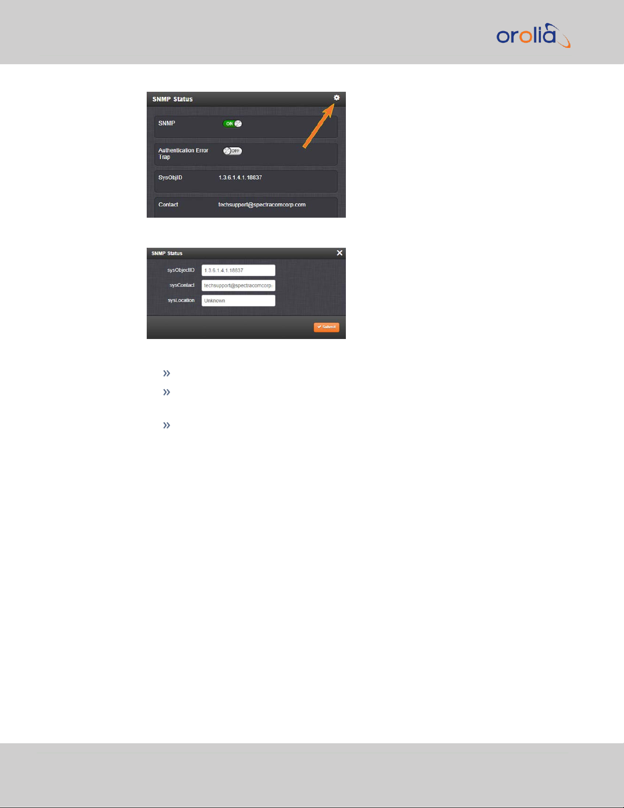
2.9 Configuring Network Settings
3.
The SNMP Status pop-up window will display:
The following settings can be configured in this window:
In the sysObjectID field, enter the SNMP system object ID.
In the sysContact field, enter the e-mail information for the system con-
tact you wish to use.
In the sysLocation field, enter the system location of your VelaSync unit.
4.
Click Submit, or cancel by clicking the X-icon in the top-right corner.
Accessing the SNMP Support MIB Files
Spectracom’s private enterprise MIB files can be extracted via File Transfer Protocol
(FTP) from VelaSync, using an FTP client such as FileZilla or any other shareware/freeware FTP program.
To obtain the MIB files from VelaSync via FTP/SFTP:
1.
Using an FTP program, log in as an administrator.
2.
Through the FTP program, locate the Spectracom MIB files in the /home/spec-
tracom/mibs directory.
3.
FTP the files to the desired location on your PC for later transfer to the SNMP
Manager.
4.
Compile the MIB files onto the SNMP Manager.
60
CHAPTER 2 • VelaSync User's Manual Rev. 3
Page 73

2.9 Configuring Network Settings
Note: When compiling the MIB files, some SNMP Manager pro-
grams may require the MIB files to be named something other
than the current names for the files. The MIB file names may be
changed or edited as necessary to meet the requirements of the
SNMP Manager. Refer to the SNMP Manager documentation for
more information on these requirements.
Note: In addition to the Spectracom MIB files, there are also
some net-snmp MIB files provided. Net-snmp is the embedded
SNMP agent that is used in the VelaSync and it provides traps to
notify the user when it starts, restarts, or shuts down. These MIB
files may also be compiled into your SNMP manager, if they are
not already present.
Spectracom’s private enterprise MIB files can be requested and obtained from
the Spectracom Customer Service department via email at
techsupport@spectracom.com.
2.9.7.1 SNMP V1/V2c
SNMP V1 is the first version of the SNMP protocol, as defined in the IETF (Internet
Engineering Task Force) RFCs (Request for Comments) number 1155 and 1157. SNMP
V2c is the revised protocol, but it also uses the V1 community based administration
model.
Creating Communities
1.
Navigate to MANAGEMENT > NETWORK: SNMP Setup.
2.
In the SNMP V1/V2 panel click the PLUS icon in the top-right corner.
Note: By default, techsupport@spectracom.com is the address
in the sysContact field of the SNMP Status panel of the SNMP
Setup page.
3.
The SNMP V1/V2c Settings for Access window will display:
CHAPTER 2 • VelaSync User's Manual Rev. 3
61
Page 74

2.9 Configuring Network Settings
4.
Enter the required information in the fields provided:
The IP Version field provides a choice of IPv4, IPV6 or both IPv4 and IPv6
(= default).
The choices offered below will change in context with the choice made in
the IP Version field.
If no value is entered in the IPv4 and/or IPv6 field, VelaSync uses the sys-
tem default address.
SNMP Community names should be between 4 and 32 characters in
length.
Permissions may be Read Only or Read/Write.
The Version field provides a choice of V1 or V2c.
5.
Click Submit. The created communities will appear in the SNMP V1/V2 panel:
Editing and Deleting Communities
To edit or delete a community you have created:
62
1.
Navigate to MANAGEMENT > NETWORK: SNMP Setup.
CHAPTER 2 • VelaSync User's Manual Rev. 3
Page 75

2.9 Configuring Network Settings
2.
Click the row of the SNMP V1/V2 panel that displays the community you wish to
edit or delete. The cursor will change from an arrow icon to a pointing finger to
indicate that the entry is clickable.
3.
The SNMP V1/V2c Settings for Access window will display.
Note: The options available for editing in the SNMP V1/V2c Set-
tings for Access window will vary contextually according to the
information in the entry chosen.
4.
To edit the settings, enter the new details you want to edit and click Submit. OR:
To delete the entry, click Delete.
2.9.7.2 SNMP V3
SNMP V3 utilizes a user- based security model which, among other things, offer
enhanced security over SNMP V1 and V2.
Creating Users
1.
Navigate to MANAGEMENT > NETWORK: SNMP Setup.
2.
In the SNMP V3 panel, click the PLUS icon in the top-right corner.
3.
The SNMP V3 Settings window will display.
CHAPTER 2 • VelaSync User's Manual Rev. 3
63
Page 76

2.9 Configuring Network Settings
4.
Enter the required information in the fields provided.
SNMP User Names and passwords are independent of users that are con-
figured on the Tools/Users page.
User names are arbitrary. SNMP User Names should be between 1
and 31 characters in length.
The User Name must be the same on VelaSync and on the man-
agement station.
The Auth Type field provides a choice between MD5 and SHA.
The Auth Password must be between 8 and 32 characters in length.
The Priv Type field provides a choice between AES and DES.
The Priv Passphrase must be between 8 and 32 characters in length.
The Permissions field provides a choice between Read/Write and Read
Only.
5.
Click Submit. The created user will appear in the SNMP V3 panel:
Editing and Deleting Users
To edit or delete a user you have created:
1.
Navigate to MANAGEMENT > NETWORK: SNMP Setup.
64
2.
Click the row of the SNMP V3 panel that displays the community you wish to edit
or delete. The cursor will change from an arrow icon to a pointing finger to indicate that the entry is clickable.
3.
The SNMP V3 Settings window will display:
CHAPTER 2 • VelaSync User's Manual Rev. 3
Page 77

4.
Apply your changes and click Submit. OR: Click Delete to remove the User.
2.9.7.3 SNMP Traps
SNMP traps allow for automatic event notification, and as such are one way to remotely
monitor VelaSync's status.
2.9 Configuring Network Settings
SNMP traps indicate the status change that caused the trap to be sent and may also
include one or more objects, referred to as variable-bindings, or varbinds. A varbind
provides a current VelaSync data object that is related to the specific trap that was
sent. For example, when a Holdover trap is sent because VelaSync either entered or
exited the Holdover mode, the trap varbind will indicate that VelaSync is either currently
in Holdover mode or not currently in Holdover mode.
For testing purposes, a command line interface command is provided. This command,
testevent, allows one, several, or all of the traps defined in the VelaSync MIB to be gen-
erated. Refer to "CLICommands" on page217 for command details.
To define SNMP Traps (Notifications):
1.
Navigate to MANAGEMENT > NETWORK: SNMP Setup.
2.
In the SNMP Traps panel, click the PLUS icon in the top-right corner.
3.
The SNMP Traps Settings window will display:
CHAPTER 2 • VelaSync User's Manual Rev. 3
65
Page 78

2.9 Configuring Network Settings
4.
Enter the required information in the fields provided. (Note that the options will
vary contextually according to your Version.)
5.
The Version field provides a choice between v1, v2c, and v3 [= default]
The Community field for the SNMP Community string. [v1, v2c]
SNMP User names should be between 4 and 32 characters in length. [v3]
Destination IP Version is a choice between IPv4 and IPv6. [v1, v2c, v3]
Destination IP is destination address for the notification and password key
to be sent. The default port is 162. [v1, v2c, v3]
The UDP Port number used by SNMP Traps [default = 162]. [v1, v2c]
Engine Id must be a hexadecimal number (such as 0x1234). The Id ori-
ginates from the MIB Browser/SNMP Manager. [v3]
1
Auth Type provides a choice between MD5 (the default) and SHA. [v3]
The Auth Password must be between 8 and 32 characters in length. [v3]
The Priv Type field provides a choice between AES and DES. [v3]
The Priv Passphrase must be between 8 and 32 characters in length. [v3]
6.
Click the Submit button at the bottom of the window. Cancel any changes by
clicking the X-icon in the top-right corner (any information entered will be lost).
7.
The SNMP trap you created will appear in the SNMP Traps panel:
66
1
Should you require the Engine IDof your unit in order to decode traps sent to an NNMI, you can use an SNMPv3
"get" value of .1.3.6.1.3.10.2.1.1 to poll your Engine ID.
CHAPTER 2 • VelaSync User's Manual Rev. 3
Page 79

2.9 Configuring Network Settings
Each row of the SNMP Traps panel includes the version of the SNMP func-
tionality, the User/Community name for the trap, the IP address/Hostname of
the SNMP Manager and values applicable only to SNMP v3, which include the
Engine ID, the Authorization Type, the Privilege Type.
You may define different SNMP Managers to whom SNMP traps can be sent over
the network. This allows for SNMP Managers in different geographical areas to
receive the same SNMP traps.
Note: Spectracom has been assigned the enterprise identifier
18837 by the IANA (Internet Assigned Numbers Authority). Spectracom’s product MIBs reside under the enterprise identifier
@18837.3.
For detailed descriptions of the objects and traps supported by the VelaSync,
please refer to the Spectracom VelaSync MIB files. See "Accessing the SNMP
Support MIB Files" on page60.
2.9.8 VLAN Support
VLAN support in VelaSync allows you to assign a VLAN ID to a specific port to facilitate
communication within your network. These VLAN interfaces have the same configuration options as the standard untagged Ethernet interfaces.
To set up VLAN interface identification tags:
1.
Navigate to MANAGEMENT > Network Setup. In the Actions panel, select VLAN.
2.
In the popup panel labeled VLAN Setup, click on the plus sign to add your VLAN
interfaces. (You can also view or delete any configured VLAN tags from this
panel).
CHAPTER 2 • VelaSync User's Manual Rev. 3
67
Page 80

2.10 Configuring NTP
3.
Select the parent interface [eth0-eth5], type in your VLAN ID, and click submit.
Repeat the process as necessary.
Your new VLAN interfaces will now be displayed in the VLAN Setup panel, listed as eth
[#].[VLAN ID].
2.10 Configuring NTP
Network Time Protocol (NTP) and Simple Network Time Protocol (SNTP) are client-
server protocols that are used to synchronize time on IP networks. NTP provides
greater accuracy and better error checking capabilities than SNTP does, but requires
more resources.
For many applications, it is not necessary to modify the NTP factory default configuration settings. It is possible, however, to change most of the settings in order to
support specific NTP applications which may require a non-standard configuration:
These features include MD5 authentication to block NTP access to parts of the network
and to broadcast NTP data to the network’s broadcast address. NTP and SNTP are used
to synchronize time on any computer equipment compatible with the Network Time
Protocol. This includes Cisco routers and switches, UNIX machines, and Windows
machines with suitable clients. To synchronize a single workstation, several freeware or
68
CHAPTER 2 • VelaSync User's Manual Rev. 3
Page 81

shareware NTP clients are available on the Internet. The software running on the PC
determines whether NTP or SNTP is used.
When the NTP service is enabled, VelaSync will “listen” for NTP request messages from
NTP clients on the network. When an NTP request packet is received, VelaSync will
send an NTP response time packet to the requesting client. Under typical conditions,
VelaSync can service several thousand NTP requests per second without MD5 authentication enabled, and at a somewhat lower rate with MD5 authentication enabled.
You can either enable or completely disable the NTP Service. When NTP is disabled, no
NTP time packets will be sent out to the network. When enabled, by default, the NTP
Service operates in Unicast mode, i.e. the NTP Service responds to NTP requests only.
Note: In order to configure NTP, you need to access the NTP Setup
screen which requires ADMINISTRATORrights.
2.10.1 Checklist NTP Configuration
2.10 Configuring NTP
The following is a list of configuration settings you may want to consider as you setup
your NTP Service. (Not all items may apply to your application, or there may be other
considerations not included in this list.)
1.
Did you setup your NTP Service and have it use the right Reference(s)?
See "NTP Reference Configuration" on page75.
2.
Does your NTP Service use the right Timescale?
See "NTP Output Timescale" on page73.
3.
If required, have you setup other NTP Servers and Peers for fallback purposes?
See "NTP Peers: Adding, Configuring, Removing" on page79.
2.10.2 The NTP Setup Screen
The NTP Setup screen provides access to all NTP configuration settings.
To open the NTP Setup screen, navigate to MANAGEMENT > NTP Setup. The NTP
Setup screen is divided into 5 panels:
CHAPTER 2 • VelaSync User's Manual Rev. 3
69
Page 82

2.10 Configuring NTP
The NTP Servers and Peers panels
… are located on the right-hand side of the NTP screen:
NTP Servers: In this display you can view the NTP Servers that VelaSync detects
in your network. It is through this display that you configure external NTP references. See "NTP Servers: Adding, Configuring, Removing" on page77.
NTP Peers: In this display you can view the NTP Peers that VelaSync detects in
your network. It is through this display that you configure NTP Peer reference
inputs. See "NTP Peers: Adding, Configuring, Removing" on page79.
For more information on NTP servers, clients, and Stratums see "NTP Servers and
Peers" on page75.
The Actions panel
… is in the top left-hand corner of the NTP screen comprises the following buttons:
Symmetric Keys: Click here to set up your symmetric keys for MD5 authen-
tication. For more information on Symmetric Keys, see "Configuring NTP Sym-
metric Keys" on page81.
Access Restrictions: Click here to view, change or delete access restrictions to
the NTP network. (See also "NTP Access Restrictions" on page84.)
Fields in the NTP Access Restrictions table include:
70
CHAPTER 2 • VelaSync User's Manual Rev. 3
Page 83

2.10 Configuring NTP
Type
IP Version
IP
IP Mask
Auth only
Enable Query
View NTP Clients: Click here to reveal a table of all the clients your VelaSync is
servicing. (See also "Viewing NTP Clients" on the next page.)
Information for each client includes:
Client IP
Received Packets
Mode
Version
Restriction Flags
Avg Interval
Last Interval
Restore Default NTP Configuration: Click here to restore VelaSync’s NTP set-
tings to the factory default. Any settings you have created previously will be lost.
See "Restoring the Default NTP Configuration" on page73.
The NTP Services panel
… is the second panel on the left-hand side of the NTP screen.
NTP ON/OFF: This switch enables and disables NTP. See "Dis-/Enabling NTP" on
the next page.
Note: When applying any changes NTP will usually restart auto-
matically. Use this switch only to force a restart.
Other NTP Services that can be configured via the NTP Services panel by clicking the
GEAR icon are:
Stratum 1 (see "NTP Reference Configuration" on page75)
The NTP Status Summary panel
… provides a real-time overview of your key NTP network parameters. For more information, see "NTP Status Monitoring" on page191 .
CHAPTER 2 • VelaSync User's Manual Rev. 3
71
Page 84

2.10 Configuring NTP
2.10.3 Dis-/Enabling NTP
If you applied NTP configuration changes e.g., added a new NTP Server, VelaSync usually
will stop and re-start the NTP Service automatically once you clicked Submit. Changes
made to NTP configurations will also take effect after VelaSync is either rebooted or
power-cycled.
You can, however, also disable or enable the VelaSync NTP Service manually.
To disable and enable your NTP Service:
1.
Navigate to MANAGEMENT > NETWORK: NTP Setup.
2.
In the NTP Services panel, set the ON/OFF toggle switch to OFF.
3.
A notification window will confirm the status change.
4.
In the NTP Services panel, set the ON/OFF toggle switch to ON again.
Changes made will now take effect and NTP operation will be restored shortly after this
operation is performed.
2.10.4 Viewing NTP Clients
To view the NTP clients being served by VelaSync:
1.
Navigate to MANAGEMENT> NETWORK: NTP Setup.
2.
In the NTP Actions panel, click View NTP Clients:
3.
The NTP Clients window will display, showing a table of the clients that are syn-
chronizing to VelaSync via NTP:
72
CHAPTER 2 • VelaSync User's Manual Rev. 3
Page 85

2.10 Configuring NTP
You can search any of the fields for specific information in the Search field
at the top of the window.
A limit of 10 entries will appear on the screen at any one time. If you have
more than 10clients, you can move through the table using the First, Pre-
vious, Next and Last navigation buttons at the bottom of the screen.
2.10.5 Restoring the Default NTP Configuration
The VelaSync default NTP configuration can be restored at any time. It comprises basic
settings such as Stratum1 operation with no other servers or peers, no broadcasting
and no access restrictions. External queries or modifications are not permitted, while
generally all IPv4 and IPv6 client connections are allowed.
To restore VelaSync to its default NTP configuration:
1.
Navigate to MANAGEMENT > NETWORK: NTP Setup.
2.
In the NTP Actions panel, click Restore Default NTP Configuration.
3.
In the dialog window that displays, click OK.
2.10.6 NTP Output Timescale
You can choose the timescale VelaSync will use for the time stamps it sends out to its
NTP clients and network nodes. This is done by setting VelaSync SystemTime times-
CHAPTER 2 • VelaSync User's Manual Rev. 3
73
Page 86

2.10 Configuring NTP
cale. The options are UTC, TAI and GPS. Typically, UTC is used for network synchronization.
Note that the System Time affects not only NTP output, but also all other aspects of
time management e.g., time distributed via channels other than NTP, logging, and time
displayed in the Web UI.
If VelaSync is operated as a Stratum2 server, i.e. as a client to a Stratum1 server (see
"NTP Stratum Synchronization" on page1), the other server will override VelaSync's
System Timescale, should it be different.
To change the system timescale VelaSync will use for its NTP output (and other outputs):
1.
Note: IMPORTANT: Make sure you select your desired timescale! Using
the wrong timescale will inevitably result in an undesired time error in
your NTP clients.
Navigate to MANAGEMENT > OTHER: Time Management:
74
2.
In the System Time panel, click the GEAR icon.
3.
In the Edit System Time window, select the System Timescale VelaSync will be
in:
UTC: The network PCs will receive UTC time via NTP.
TAI: The network PCs will receive TAI time via NTP.
GPS: The network PCs will receive GPS time via NTP.
CHAPTER 2 • VelaSync User's Manual Rev. 3
Page 87

Note: When the Timescale is set to “GPS”, the GPS to UTC
Offset must be set correctly. As of 26-Oct-2018, the offset
between UTC and GPS is 18 seconds.
2.10.7 NTP Reference Configuration
VelaSync's NTP Service needs to be setup such that it utilizes the time source ("input
reference") you want it to use. There are two options for an NTP Server to derive its
time from:
a.
The NTP Service uses VelaSync's System Time System Time is the time derived
from the internal Timing System. The Timing System is the time server's central
time processing engine. It consumes and processes time and 1PPS obtained from
an external input reference e.g., typically GNSS., i.e. typically the GNSS reference
(or IRIG, ASCII data input, etc.), and distributes that time over the NTP network.
This is called Stratum 1 Operation, because VelaSync will be the Stratum1 (or
primary) server. This is the most common configuration.
2.10 Configuring NTP
2.10.8 NTP Servers and Peers
VelaSync can be configured to receive time from one or more available NTP Servers
(VelaSyncs or different models). This allows for NTP Servers on a timing network to be
configured as potential (fallback) input time references for VelaSync System Time synchronization. In the event that a current reference becomes unavailable, VelaSync can
fallback to the other NTP Servers available on the network.
A group of NTP servers at the same Stratum level (Stratum 1 time servers, for
example) are considered as NTP Peers to each other.
NTP Servers at the same Stratum level
If VelaSync is configured to obtain time from other NTP Servers at the same Stratum
level (i.e., NTP Peers) but is currently using a different input reference as its selected reference, VelaSync will report to the network (via the NTP time stamps) that it is a
Stratum1 time server. Should, however, all input references except the other NTP
server(s) become unavailable, VelaSync will then drop to a Stratum2 time server (with
System Time being derived from the NTP time packets being received from the other
NTP Peers.
Holdover
If VelaSync is synchronized to another NTP Server or reference, and that server or reference subsequently loses sync or becomes unavailable (with no other higher priority
input references being present and valid), VelaSync will then go into the Holdover mode.
CHAPTER 2 • VelaSync User's Manual Rev. 3
75
Page 88

2.10 Configuring NTP
It will remain in Holdover mode until any enabled and valid input reference becomes available again, or until the Holdover period expires, whichever occurs first.
During Holdover mode, NTP will remain at the same Stratum level it was before entering the Holdover mode and can continue to be the reference to the network. However,
if no input reference becomes available before the Holdover period expires, Time Sync
will be lost and shortly thereafter, NTP will report to the network that it is now at
Stratum15. A status of Stratum15 will cause the network to ignore VelaSync as an NTP
time reference.
For more information about Holdover, see "Holdover Mode" on page148.
2.10.8.1 The NTP Servers and NTP Peers Panels
The NTP Servers and NTP Peers panels display which servers in the network are set
up at higher or equal Stratums (Servers or Peers, respectively), and their configurations. These panels are also used to add, configure, or remove NTP Servers and
Peers.
Note: For information on how to view NTP Clients, see "Viewing NTP
Clients" on page72.
The NTP Servers and NTP Peers panels are part of the NTP Setup screen (see "The
NTP Setup Screen" on page69 ), which can be accessed via MANAGEMENT >
NETWORK: NTP Setup.
Information provided in the NTP Servers and NTP Peers panels
The following columns are used to break down the status information for recognized
NTP Servers and NTP Peers.
76
CHAPTER 2 • VelaSync User's Manual Rev. 3
Page 89

2.10 Configuring NTP
Note: Servers will be displayed in the Status view only if they can be
resolved. They will, however, always be displayed in the Setup view in
order to reconfigure them, if necessary.
IP/HOST: Name and real-time status (color-coded)
REF ID: Identifies the type of Input REFerence e.g., GPS indicates the reference
can use GPS for its synchronization. Below is a list of potential REF IDs reported
by the VelaSync Timing System (otherNTP Servers and Peers may report different references):
GPS: GNSS reference
IRIG: IRIG reference
HVQ: HAVE QUICK reference
FREQ: Frequency reference
PPS: External 1PPS reference
PTP: PTP reference
ATC: ASCII time code reference
USER: User provided time
LOCL: Local reference (synced to itself)
INIT: NTP on server/peer is initializing
STEP: NTP on server/peer is performing initial synchronization step and
restarting
AUTH STATUS: Indicates if the selected reference is using MD5 authentication.
“None” indicates authentication not being used.
LAST: The number of seconds that have expired since this reference was last
polled for its time.
POLL: The polling interval, i.e. how often VelaSync is polling this NTP reference
for its time.
DELAY (ms): The measured one-way delay between VelaSync and its selected
reference.
2.10.8.2 NTP Servers: Adding, Configuring, Removing
To add, configure, or remove an NTP Server:
CHAPTER 2 • VelaSync User's Manual Rev. 3
77
Page 90

2.10 Configuring NTP
1.
Navigate to MANAGEMENT > NETWORK: NTP Setup.
2.
The NTP Setup screen appears. The NTP Servers panel displays a list of recog-
nized NTP servers. Click the GEAR icon in the upper right-hand corner of the NTP
Servers panel.
3.
The NTP Servers window opens. Should the list be empty, no servers have been
added yet. In the event that added servers are not displayed in the NTP Setup
screen/NTP Servers panel, they could not be resolved. Verify the IP address.
Note that System servers cannot be edited or deleted.
To ADD a new server, click the PLUS icon in the upper right-hand corner,
and proceed to the next step.
Note: In order for other NTP Servers to be a valid ref-
erence, “NTP” must be enabled as both the Time and 1PPS
references in the Reference Priority table. See "Con-
figuring Input Reference Priorities" on page112.
To EDIT an existing server, click the corresponding ACTIONGEAR button,
and proceed to the next step.
To REMOVE a server (and its associated configurations), click the X-button
next to it, then confirm by clicking OK.
78
CHAPTER 2 • VelaSync User's Manual Rev. 3
Page 91

2.10 Configuring NTP
4.
The NTP Server Edit window displays. Enter the required information:
Host: The IP address for the server to be used as host.
Min Poll Interval: Select a value from the drop down (the default is 3 (8s)).
Max Poll Interval: Select a value from the drop down (the default is 3 (8s)).
For both NTP Peers, and NTP Servers the Minimum and Maximum Poll rate
for NTP packets can be configured.
Enable Burst: This tells NTP to send a burst to the remote server when
the server is reachable.
Enable Iburst: The iburst function tells NTP to send a burst of queries
instead of one when the remote server is not reachable for faster clock synchronization. This will occur if the connection was interrupted, or upon
restart of the NTP daemon. For additional information, please refer to public NTP configuration documentation.
Mark as Preferred: Click here to make this server the preferred server.
For more information, see "NTP Timing System: Reference Selection and
Preference" page 1.
Note: It is not normally recommended to select more than
one NTP Server in the NTP Servers table as being Pre-
ferred. Typically, only one NTP server should be selected as
Preferred.
5.
Click Submit, or press Enter.
2.10.8.3 NTP Peers: Adding, Configuring, Removing
To add, configure, or remove an NTP Peer:
1.
Navigate to MANAGEMENT > NETWORK: NTP Setup.
2.
The NTP Setup screen appears. The NTP Peers panel displays a list of recognized
NTP peers.
Note: Should the list be empty, no servers have been added yet.
In the event that added peers are not displayed, they could not
be resolved. Verify the IPaddress
To EDIT the settings of an NTP Peer, click the GEAR button next to it, and
proceed to Step3 below.
CHAPTER 2 • VelaSync User's Manual Rev. 3
79
Page 92

2.10 Configuring NTP
3.
To ADD a new NTP Peer, click the PLUS icon in the top right corner of the
NTP Peers panel.
To REMOVE an NTP Peer (and its associated configurations), click the X-
button next to it.
The NTP Peers edit window opens:
4.
Enter the required information into the fields:
Host: The IPaddress for the server to be used as host.
Min Poll Interval: Select a value from the drop down (the default is 3 (8s).
Max Poll Interval: Select a value from the drop down (the default is 3 (8s).
For both NTP Peers, and NTP Servers the Minimum and Maximum Poll rate
for NTP packets can be configured.
Enable Symmetric Key: Click the checkbox to enable/disable Symmetric
Key. See also: "Configuring NTP Symmetric Keys" on the facing page.
Note: Before you can edit the Key field, you must set up
Symmetric Keys through the Actions Panel. See "NTP: Sym-
metric Keys (MD5) " on the facing page.
Mark as Preferred: Check this box to prefer this NTP Peer over other NTP
Peers ("NTP Peer Preference"). This will result in VelaSync synchronizing
more frequently with this Peer. For additional information on NTP Preferences, see "NTP Timing System: Reference Selection and Preference" on
page 1.
80
CHAPTER 2 • VelaSync User's Manual Rev. 3
Page 93

Note: Please note that it is not advisable to mark more
than one NTP Peer as Preferred, even though VelaSync will
not prevent you from doing so.
5.
Click Submit, or press Enter.
2.10.9 NTP Authentication
Since NTP information is distributed across entire networks, NTP poses a security
risk:Falsified NTP time stamps or other NTP-related information can be exploited by an
attacker. NTP authentication keys are used to authenticate time synchronization, thus
detecting a fake time source before it can do harm.
2.10.9.1 NTP: Symmetric Keys (MD5)
2.10 Configuring NTP
Symmetric Keys are an encryption means that can be used with NTP for authentication
purposes.
VelaSync supports authenticated NTP packets using an MD5 authenticator. This feature does not encrypt the time packets, but attaches an authenticator, which consists
of a key identifier and an MD5 message digest, to the end of each packet. This can be
used to guarantee that NTP packets came from a valid NTP client or server, and that
they were not tampered with during transmission. The Symmetric Keys tab allows NTP
to be configured to use MD5 authentication.
Configuring NTP Symmetric Keys
To create, edit, or delete Symmetric Keys (MD5 Authentication):
1.
Navigate to MANAGEMENT > NETWORK: NTP Setup.
2.
In the Actions panel, click the Symmetric Keys button:
3.
The NTP Symmetric Keys window will display:
CHAPTER 2 • VelaSync User's Manual Rev. 3
81
Page 94

2.10 Configuring NTP
4.
To CREATE a Symmetric Key, click the PLUS icon in the top-right corner,
and proceed to Step4.
To EDIT an existing key pair, click the corresponding Change button, and
proceed to Step4.
To DELETE a key pair, click the corresponding Delete button, and click OK
in the dialog box to confirm and complete the procedure.
The NTP Symmetric Key window will display:
82
Fill in, or edit the fields:
Trusted (checkbox)—Check this box to use MD5 authentication with trus-
ted key ID.
Note: To use the MD5 authentication with trusted key ID,
both the NTP client and the VelaSync must contain the
same key ID/key string pair, the client must be set to use
one of these MD5 pairs, and the key must be trusted.
Key ID—The key ID must be a number between 1 and 65532.
Digest Scheme—Choose one of the options from the drop-down list. The
available options are:
CHAPTER 2 • VelaSync User's Manual Rev. 3
Page 95

2.10 Configuring NTP
MD5 (the default)
SHA1
SHA
MDC2
MDC2
RIPEMD160
MD4
Key Str— The key string must be readable ASCII and between 1 and 16
characters long.
5.
Click the Submit button: The changes will be reflected in the table of the NTP
Symmetric Keys window, which is displayed after clicking the Submit button.
6.
The key(s) you have set up will now appear as options in the Symmetric Key field
in both the NTP Server screen, and the NTP Peer screen.
CHAPTER 2 • VelaSync User's Manual Rev. 3
83
Page 96
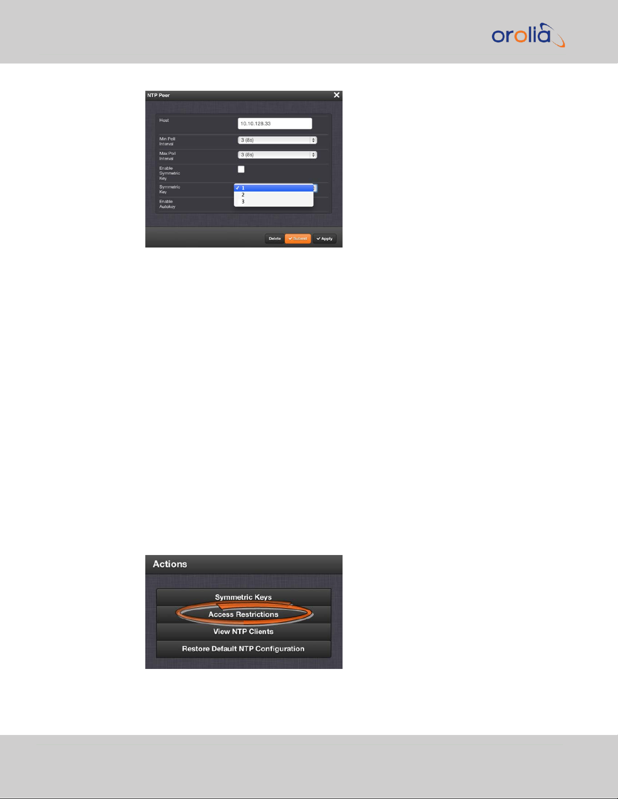
2.10 Configuring NTP
NOTES:
Duplicate key IDs are not permitted. NTP requests received by that do not contain an
authenticator containing a valid Key ID and MD5 message digest pair will be responded
to, but no authentication will be performed. An NTP request with valid authenticators
results in a valid NTP response with its own valid authenticator using the same Key ID
provided in the NTP request.
You may define the trusted Symmetric Keys that must be entered on both VelaSync,
and any network client with which VelaSync is to communicate. Only those keys for
which the “Trusted” box has been checked will appear in the dropdown menus on the
NTP References screen.
2.10.10 NTP Access Restrictions
Next to encrypted authentication by means of Symmetric Keys, NTP supports a listbased means of access restriction, the use of which is also recommended to prevent
fraudulent or inadvertent manipulation of a time server.
To configure NTP Access Restrictions:
1.
Navigate to MANAGEMENT > NETWORK: NTP Setup.
2.
In the Actions panel, click Access Restrictions:
84
CHAPTER 2 • VelaSync User's Manual Rev. 3
Page 97

3.
The NTP Access Restrictions Status window will display:
To ADD or EDIT an access restriction, click the PLUS icon or the Change
button, respectively, and proceed to Step4. below.
To DELETE an access restriction, click the corresponding Delete button,
and confirm by clicking OK.
4.
The NTP Access Restrictions window will display:
2.10 Configuring NTP
Fill in the fields:
Restriction Type—Choose either Allow or Deny.
If you select “Deny”, the configured portion of the network will not
have NTP access to VelaSync, but the rest of the network will have
access to VelaSync. If you select “allow”, the configured portion of
the network will have NTP access to VelaSync, but the rest of the
network will not have access to VelaSync. By default, VelaSync
allows all IPv4 and IPv6 connections.
IP Version—Choose IPv4 or IPv6
IP Address—Enter the appropriate hostname.
Subnet Mask—Enter the appropriate IP mask.
CHAPTER 2 • VelaSync User's Manual Rev. 3
85
Page 98

2.11 Configuring PTP
Require Authentication (checkbox)—Check this box if you want the
additional security of authorized access. VelaSync to accept only
authenticated requests (MD5) from this user or network segment.
Allow NTP Queries (checkbox)—Check this box if you want to allow
external NTP queries into VelaSync services.
5.
Click the Submit button.
2.10.11 Spectracom Technical Support for NTP
Spectracom does not provide technical assistance for configuring and installing NTP on
Unix-based applications. Please refer to www.ntp.org for NTP information and FAQs.
Another helpful source is the Internet newsgroup at
news://comp.protocols.time.ntp.
Spectracom can provide support for Microsoft® Windows-based time synchronization.
See spectracom.com for additional information, or contact Spectracom Technical Support.
2.11 Configuring PTP
Precision Time Protocol (PTP) is a time protocol that can be used to synchronize computers on an Ethernet network. VelaSync supports PTP Version1 and2, as specified in
the IEEE 1588-2002 and IEEE 1588-2008 standard, via four (4) Ethernet ports.
VelaSync currently can be configured as a PTP Master Clock only.
Next to PTP specifications, this topic describes the PTP menu items and settings, and
outlines how to set up VelaSync as a PTP Master.
PTP Specifications
Inputs/Outputs: (4) Port
Signal Type: Ethernet
Management: Web UI
Network Speeds: 100 Mb/s, 1Gb/s, or 10Gb/s
PTP Version supported:PTP1 IEEE (1588-2002) and 2 (IEEE 1588-2008)
PTP Profiles supported: Default, Telecom, Enterprise
Transmission modes: Unicast, Multicast (IPv4 and Ethernet), and Hybrid
[default]
86
Timestamping: VelaSync has PTP time stamp functionality which is set to use
the UTC timescale.
CHAPTER 2 • VelaSync User's Manual Rev. 3
Page 99

2.11.1 The PTP Screen
The PTP screen provides PTP status information, and provides access to all configurable
PTP settings.
To access the PTP screen, navigate to MANAGEMENT > NETWORK: PTP Setup. The
PTP screen will open:
2.11 Configuring PTP
Figure 2-10: VelaSync PTP screen
For each Ethernet port (ETH0-ETH3) you can toggle PTP functionality ON or OFF.
You can also access the "Settings" panel and the "Statistics" panel for each port (see
below).
2.11.1.1 The PTP Settings Panel
The Settings Panel provides access to the configuration settings, divided into three
tabs, which are described below. Each tab allows you to Restore defaults.
Note: The Restore Defaults button in each PTP Settings panel will
restore ALL the factory defaults for ALL Ethernet ports.
CHAPTER 2 • VelaSync User's Manual Rev. 3
87
Page 100

2.11 Configuring PTP
Settings changed by the user will be maintained when the PTPdaemon is stopped and
started, and between reboots and powercycles.
Figure 2-11: Edit PTP Settings panel
Protocol tab
PTP version: [1, 2] Select Version 1 or Version 2.
Domain: [1 through 127] Sets the current PTP Domain Number, as defined in
IEEE Std 1588-2008 Section 7.1
Communication Mode: Select multicast, hybrid, or unicast mode.
A b o u t … P T P T r a n s m i s s i o n M o d e s
The PTP Card is able to transmit the PTP packets in three transmission modes:
• Multicast Mode: PTP packets are transmitted to all PTP Clocks by means of
Multicast IP addresses dedicated to the PTP protocol (224.0.1.129, 224.0.0.107). PTP
packets received by the PTP Clocks are then filtered from the Domain Number, the
Port Identity (Clock Identity + Port Number) of the transmitter. When the Master
Clock is set in Multicast mode, this module will deny the requests from the Slaves
Clocks to run in Unicast mode. When the Master Clock is set in Unicast mode, it
doesn’t transmit any PTP messages until a Slave has been granted to run in Unicast
mode.
• Unicast Mode: This is a Point-to-Point transmission mode between two PTP
Clocks by means of the unique IP address assigned to each PTP Clock.
• Hybrid Mode: [default] This mode uses Multicast messages for Sync, Follow-Up,
and Announce packets from the Master. Slaves are expected to send Delay Request
messages to the Master in Unicast, and the Master responds in Unicast. No Unicast
Negotiation grants are necessary.
88
CHAPTER 2 • VelaSync User's Manual Rev. 3
 Loading...