

Spectracom TV210V, TV210U, TV210W, TV400V, TV400U Instruction Manual
...
TIMEVIEW DIGITAL DISPLAY CLOCK
MODELS TV210V, U, G, W & TV400V, U, G, W
INSTRUCTION MANUAL
SPECTRACOM CORPORATION
95 METHODIST HILL DRIVE
ROCHESTER, NY 14623
PHONE 585.321.5800
FAX 585.321.5219
www.spectracomcorp.com
Part Number 1144-5000-0050
Manual Revision A
November 2005

Copyright © 2005 Spectracom Corporation. The contents of this publication may not be
reproduced in any form without the written permission of Spectracom Corporation. Printed in
USA.
Specifications subject to change or improvement without notice.
Spectracom, NetClock, Ageless, TimeGuard, TimeBurst, TimeTap, LineTap, MultiTap,
VersaTap, and Legally Traceable Time are Spectracom registered trademarks. All other
products are identified by trademarks of their respective companies or organizations. All rights
reserved.

SPECTRACOM LIMITED WARRANTY
LIMITED WARRANTY
Spectracom warrants each new product manufactured and
sold by it to be free from defects in software, material,
workmanship, and construction, except for batteries, fuses, or
other material normally consumed in operation that may be
contained therein AND AS NOTED BELOW, for five years after
shipment to the original purchaser (which period is referred t o
as the “warranty period”). This warranty shall not ap ply if the
product is used contrary to the instructions in its manual or is
otherwise subjected to misuse, abnormal operations, accident,
lightning or transient surge, repairs or modifications not
performed by Spectracom.
The GPS receiver is warranted for one year from date of
shipment and subject to the exceptions listed above. The
power adaptor, if supplied, is warranted for one ye ar from date
of shipment and subject to the exceptions listed above.
THE ANALOG CLOCKS ARE WARRANTED FOR ONE YEAR
FROM DATE OF SHIPMENT AND SUBJECT TO THE
EXCEPTIONS LISTED ABOVE.
THE TIMECODE READER/GENERATORS ARE WARRANTED FOR ONE YEAR FROM DATE OF SHIPMENT AND
SUBJECT TO THE EXCEPTIONS LISTED ABOVE.
The Rubidium oscillator, if supplied, is warranted for two years
from date of shipment and subject to the exceptions listed
above.
All other items and pieces of equipment not specified above,
including the antenna unit, antenna surge suppressor and
antenna pre-amplifier are warranted for 5 years, subject to the
exceptions listed above.
WARRANTY CL AIMS
Spectracom’s obligation under this warranty is limited to infactory service and repair, at Spectracom’s option, of the
product or the component thereof, which is found to be
defective. If in Spectracom’s judgment the defective condition
in a Spectracom product is for a cause listed above for which
Spectracom is not responsible, Spectracom will make the
repairs or replacement of components and charge its then
current price, which buyer agrees to pay.
Spectracom shall not have any warranty obligations if the
procedure for warranty claims is not followed. Users must
notify Spectracom of the claim with full information as to the
claimed defect. Spectracom products shall not be returned
unless a return authorization number is issued by Spectracom.
Spectracom products must be returned with the description of
the claimed defect and identification of the individual to be
contacted if additional information is needed. Spectracom
products must be returned properly packed with transportation
charges prepaid.
Shipping expense: Expenses incurred for shipping
Spectracom products to and from Spectracom (including
international customs fees) shall be paid for by the customer,
with the following exception. For customers located within the
United States, any product repaired by Spectracom under a
“warranty repair” will be shipped back to the customer at
Spectracom’s expense unless special/faster delivery is
requested by customer.
Spectracom highly recommends that prior to returning
equipment for service work, our technical support department
be contacted to provide trouble shooting assistance while the
equipment is still installed. If equipment is returned without
first contacting the support department and “no problems are
found” during the repair work, an evaluation fee may be
charged.
EXCEPT FOR THE LIMITED WARRANTY STATED ABOVE,
SPECTRACOM DISCLAIMS ALL WARRANTIES OF ANY
KIND WITH REGARD TO SPECTRACOM PRODUCTS OR
OTHER MATERIALS PROVIDED BY SPECTRACOM,
INCLUDING WITHOUT LIMITATION ANY IMPLIED
WARRANTY OR MERCHANTABILITY OR FITNESS FOR A
PARTICULAR PURPOSE.
Spectracom shall have no liability or responsibility to the
original customer or any other party with respect to any liabi l it y,
loss, or damage caused directly or indirectly b y an Spectracom
product, material, or software sold or provided by Spectracom,
replacement parts or units, or services provided, including but
not limited to any interruption of service, excess charges
resulting from malfunctions of hardware or software, loss of
business or anticipatory profits resulting from the use or
operation of the Spectracom product or software, whatsoever
or howsoever caused. In no event shall Spectracom be liabl e
for any direct, indirect, special or consequential damages
whether the claims are grounded in contract, tort (including
negligence), or strict liability.
EXTENDED WARRANTY COVERAGE
Extended warranties can be purchased for additional periods
beyond the standard five-year warranty. Contact Spectracom
no later than the last year of the standard five-year warranty for
extended coverage.
SPECTRACOM 95 Methodist Hill Drive Rochester, NY 14623
+1.585.321.5800 FAX: +1.585.321.5218 www.spectracomcorp.com sales@spectracomcorp.com


Spectracom Corporation TV210V, U, G, W & TV400 V, U, G, W
Table of Contents
1 INTRODUCTION ..................................................................................... 1-1
1.1 Wired Clock Features....................................................................................................................1-3
1.2 Wireless Clock Features................................................................................................................1-3
1.3 Warranty Information and Product Support...................................................................................1-4
1.4 Manual Errata and Special Documentation...................................................................................1-4
1.5 Unpacking......................................................................................................................................1-5
1.6 Specifications................................................................................................................................1-6
1.6.1 TimeView 210 Wired.............................................................................................................1-7
1.6.2 TimeView 210 Wireless ........................................................................................................ 1-8
1.6.3 TimeView 400 Wired.............................................................................................................1-9
1.6.4 TimeView 400 Wireless ......................................................................................................1-10
2 INSTALLATION ....................................................................................... 2-1
2.1 Mounting Instructions ....................................................................................................................2-1
2.1.1 Wall Mounting – TimeView 210 Series .................................................................................2-1
2.1.2 Bulkhead Mounting – TimeView 210 Series..........................................................................2-2
2.1.3 Wall Mounting – TimeView 400 Series .................................................................................2-2
2.2 Power – TimeView 210 Series.......................................................................................................2-3
2.3 Power – TimeView 400 Series.......................................................................................................2-3
2.4 Wired Clock Configuration.............................................................................................................2-4
2.4.1 Display Settings....................................................................................................................2-5
2.4.2 Setting the Time....................................................................................................................2-6
2.4.3 Setting the Group and Sub-Group Addresses.......................................................................2-6
2.4.4 Exit Configuration Mode........................................................................................................2-8
2.4.5 RS-485 Connection...............................................................................................................2-9
2.5 Wireless Clock Configuration.......................................................................................................2-12
2.5.1 RF Meter.............................................................................................................................2-14
2.5.2 Setting the Buzzer Volume .................................................................................................2-16
2.5.3 Setting the Radio Frequency...............................................................................................2-17
2.5.4 Display Settings..................................................................................................................2-18
2.5.5 Exit Configuration Mode......................................................................................................2-19
2.5.6 TimeBurst Configuration.....................................................................................................2-19
2.5.7 Wired RS-485 Ports............................................................................................................2-20
2.5.8 Verifying Operation.............................................................................................................2-21
TimeView Digital Display Clocks Instruction Manual iii

TV210V, U, G, W & TV400 V, U, G, W Spectracom Corporation
List of Figures
Figure 1-1: Spectracom TV210 Series (Front)............................................................................................1-1
Figure 1-2: Spectracom TV400 Series (Front)............................................................................................1-2
Figure 2-1: Duplex Mounting Holes............................................................................................................2-1
Figure 2-2: Duplex Mounting Holes............................................................................................................2-2
Figure 2-3: TimeView 210W Rear Panel....................................................................................................2-4
Figure 2-4: RS-485 Connection..................................................................................................................2-9
Figure 2-5: Installation Using Repeater Output.........................................................................................2-10
Figure 2-6: Repeater Output Use..............................................................................................................2-10
Figure 2-7: Termination Resistor..............................................................................................................2-11
Figure 2-8: TimeView 210 Rear Panel......................................................................................................2-12
Figure 2-9: Rear Panel Ports....................................................................................................................2-20
List of Tables
Table 1-1: Ancillary Kits...................................................................................................... ........................1-5
Table 1-2: External Antennas.....................................................................................................................1-5
Table 2-1: Mode Switch Function Chart......................................................................................................2-5
Table 2-2: Mode Switch Function Chart....................................................................................................2-13
TimeView Digital Display Clocks Instruction Manual iv

Spectracom Corporation TV210V, U, G, W & TV400 V, U, G, W
1 Introduction
The Spectracom TimeView digital models are synchronized display clocks visible from
at least 75 feet (23 meters – TV210 series) to 150 feet (46 meters – TV400 series).
Both clocks have large, easily seen LED digits – 2.3 inches (58.4 mm) in the TV210
series and 4 inches (101.6 mm) in the TV400 series.
The TimeView digital clocks are part of Spectracom Corporation’s display family of
products, used to distribute accurate and traceable timing throughout a single facility or
across an entire community. In addition to the digital display clocks, Spectracom offers
TimeView 312 wired and wireless analog display clocks.
Spectracom’s digital clocks display Legally Traceable Time® in 12- and 24-hour formats
when referenced to a NetClock
TimeView digital clocks are RS-485 wired data input (210W and 400W models) and
wireless (TV210V, TV400V, TV210U, TV400U, TV210G, TV400G). Check the serial
tag on the rear panel of your unit to determine the model number of your equipment.
Figure 1-1: Spectracom TV210 Series (Front)
Spectracom currently offers NetClock GPS synchronized receivers and previously
offered WWVB synchronized receivers. In wireless applications, the NetClock feeds a
continuous time data stream to a Model 8185 TimeBurst™. The TimeBurst connects to
the customer’s radio console or transmitter to provide wireless synchronization. On a
schedule chosen by the customer, the TimeBurst automatically keys the transmitter and
sends a short coded time of day message in the form of a digital burst. TimeBurst is
“polite” to voice communications and will wait for “clear air” to transmit.
The wired digital display clocks have no radio receivers. Each Spectracom wired
display product connects to an RS-485 continuous time data stream provided by a
NetClock receiver or the RS-485 output of an Ethernet time server. The wired display
clocks decode the time data stream and then synchronize to within 250 milliseconds of
the traceable NetClock receiver.
®
receiver. The synchronization options available for the
TimeView Digital Display Clocks Instruction Manual 1-1

TV210V, U, G, W & TV400 V, U, G, W Spectracom Corporation
Figure 1-2: Spectracom TV400 Series (Front)
The wireless TimeView digital display clocks have internal radio receivers, built-in and
optional (TV210 series) external antennas, or required and included (TV400 series)
external antennas. Each wireless TimeView clock decodes the TimeBurst transmission
and synchronizes to within 250 milliseconds of the traceable NetClock receiver.
Spectracom offers VHF FM, UHF FM commercial, and UHF FM government band
versions of the digital TimeView clocks. Specify TimeView 210V or 400V for VHF FM
frequencies, TimeView 210U or 400U for UHF FM commercial, and TimeView 210G or
400G for UHF FM government band.
210 Series 400 Series
Wired
Wireless
TV210W TV400W
TV210V TV400V
TV210U TV400U
TV210G TV400G
TimeView Digital Display Clocks Instruction Manual 1-2

Spectracom Corporation TV210V, U, G, W & TV400 V, U, G, W
-
1.1 Wired Clock Features
Spectracom’s wired digital display clocks offer the following features:
• Accuracy: TimeView digital clocks display Legally Traceable Time when referenced
to a NetClock. The time is accurate to within 250 milliseconds of the NetClock’s
time.
• Exceptional Visibility: Large LED digits – 2.3 inches (58.4 mm) in the TV210 series
and 4 inches (101.6 mm) in the TV400 series – and anti-glare display filters provide
optimum viewing.
• Configurable Time Display: Each clock can be configured to display time in either
12- or 24-hour format.
• Ease of Installation: Automatic data format and baud rate detection makes setup
and installation easy.
1.2 Wireless Clock Features
Spectracom’s wireless digital display clocks offer the following features:
• Wireless Synchronization to NetClock via TimeBurst and Radio: The wireless
communication link eliminates costly wiring and labor expenses while simplifying
installation.
• Accuracy: TimeView digital clocks display Legally Traceable Time when connected
to a NetClock. The time is accurate to within 250 milliseconds of the NetClock’s
time.
• Exceptional Visibility: Large LED digits – 2.3 inches (58.4 mm) in the TV210 series
and 4 inches (101.6 mm) in the TV400 series – and anti-glare display filters provide
optimum viewing.
• Configurable Time Display: Each clock can be configured to display time in either
12- or 24-hour format.
• Received Signal Strength Indicator: A digital RF meter provides a quick method to
assess radio signal coverage and simplifies installation.
• RS-485 Output: Serial time code data is provided to connect to products requiring
RS-485 data input. This allows a wireless clock to synchronize Spectracom wired
display clocks and TimeTap
®
devices.
TimeView Digital Display Clocks Instruction Manual 1
3

TV210V, U, G, W & TV400 V, U, G, W Spectracom Corporation
1.3 Warranty Information and Product Support
Warranty information is found on the leading pages of this manual. Should it become
necessary to exercise the warranty, contact Spectracom Corporation to obtain a
replacement or service.
Spectracom continuously strives to improve its products and greatly appreciates any
and all customer feedback given. Please participate in Spectracom’s Customer
Satisfaction Survey found on our web site, http://www.spectracomcorp.com.
Technical support is available by telephone, via e-mail, or online. Please direct any
comments or questions regarding application, operation, or service to Spectracom’s
Customer Service department. Customer Service is available Monday through Friday
from 8:30 a.m. to 5:00 p.m. EST. Customer Service can be reached by phone at
585.321.5800.
Please contact Customer Service to obtain a Return Material Authorization Number
(RMA#) before returning any instrument to Spectracom. Please provide the serial
number and failure symptoms. Shipping to the factory is to be prepaid by the customer.
After obtaining the RMA#, ship the unit back to the following address:
Spectracom Corporation
Repair Department, RMA# xxxxx
95 Methodist Hill Drive
Rochester, NY 14623
Product support is also available by e-mail. Questions on equipment operation and
applications may be e-mailed to Spectracom Sales Support
sales@spectracomcorp.com
Repair or technical questions may be e-mailed directly to Spectracom’s technicians:
techsupport@spectracomcorp.com
Visit our web page for product information, application notes, and upgrade notices as
they become available:
http://www.spectracomcorp.com
1.4 Manual Errata and Special Documentation
Information concerning manual corrections or product changes occurring after printing is
found in the Errata Section. The Errata Section, when required, is found at the end of
this manual. Please review and incorporate changes into the manual whenever an
Errata Section is included.
Spectracom will make instrument modifications on special request. A documentation
packet associated with the modification will be provided in addition to this manual.
TimeView Digital Display Clocks Instruction Manual 1-4
Spectracom Corporation TV210V, U, G, W & TV400 V, U, G, W
-
1.5 Unpacking
On receipt, carefully examine the carton and its contents. If there is damage to the
carton resulting in damage to the unit, contact the carrier immediately. Retain the carton
and packing materials in the event the carrier wishes to witness the shipping damage.
Failing to report shipping damage immediately may forfeit any claim against the carrier.
In addition, notify Spectracom Corporation of shipping damage or shortages to obtain a
replacement or repair services.
Remove the packing list from the envelope on the outside of the carton. Check the
packing list against the contents to be sure all items have been received, including an
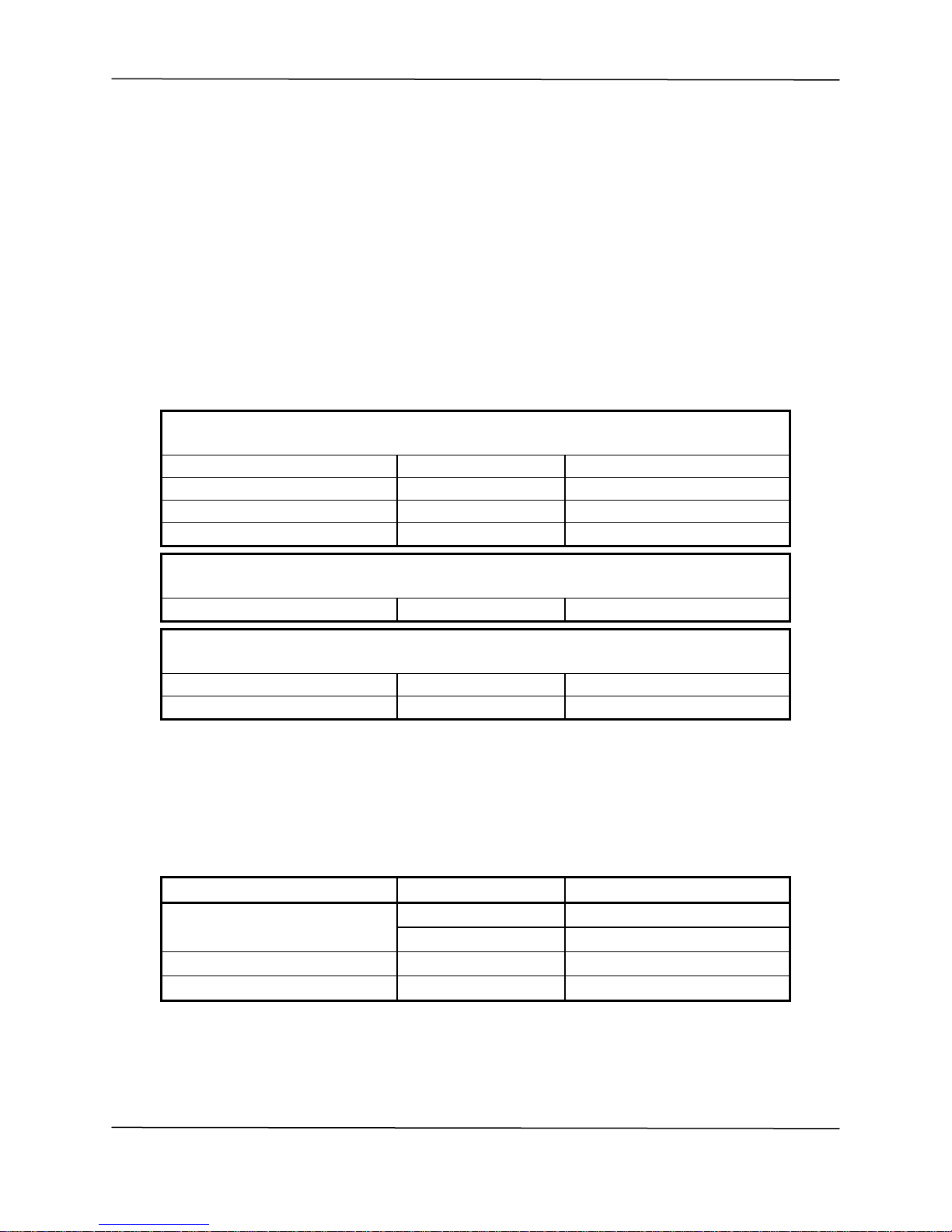
instruction manual and ancillary kit. Table 1-1 lists the items included in the various
ancillary kits.
Ancillary Kit Items Supplied with All Display Clocks
Description Part Number Quantity
Plastic Anchor HD0001 2
Screw, #6 x 1” H100-1000-0016 2
Terminal Strip P13006 1
Resister, 120 Ohms R02121 1
Ancillary Kit Items Supplied with 210 Series Only
Description Part Number Quantity
Power Adapter, 12 VDC PS03-0T0J-WM01 1
Ancillary Kit Items Supplied with 400 Series Only
Description Part Number Quantity
Power Adapter, 12 VDC PS06-0E0J-DT01 1
Line Cord W01000 1
Table 1-1: Ancillary Kits
Wireless units ordered with an optional external antenna (210 series) or shipped with a
required, included antenna (400 series) receive an antenna suited for the specified
frequency band. Refer to Table 1-2 and verify that the appropriate antenna has been
shipped with your unit(s).
Frequency Band Frequency Range Spectracom Par t Number
VHF
UHF Commercial 400-512 MHz E030-0005-0450
UHF Government 400-420 MHz E030-0002-0420
Table 1-2: External Antennas
150-162 MHz E030-0003-0150
160-174 MHz E030-0004-0160
TimeView Digital Display Clocks Instruction Manual 1
5

TV210V, U, G, W & TV400 V, U, G, W Spectracom Corporation
1.6 Specifications
Refer to sections 1.6.1, 1.6.2, 1.6.3, and 1.6.4 for digital display clock specifications.
TimeView Digital Display Clocks Instruction Manual 1-6
 Loading...