

Page 1
SecureSync
Time and Frequency
Synchronization System
®
User Reference Guide
Document Part No.: 1200-5000-0050
Revision: 26
Date: 25-May-2018
spectracom.com
Page 2

Page 3

© 2018 Spectracom. All rights reserved.
The information in this document has been carefully reviewed and is
believed to be accurate and up-to-date. Spectracom assumes no responsibility for any errors or omissions that may be contained in this document,
and makes no commitment to keep current the information in this manual, or
to notify any person or organization of updates. This User Reference Guide
is subject to change without notice. For the most current version of this documentation, please see our web site at spectracom.com.
Spectracom reserves the right to make changes to the product described in
this document at any time and without notice. Any software that may be
provided with the product described in this document is furnished under a
license agreement or nondisclosure agreement. The software may be used
or copied only in accordance with the terms of those agreements.
No part of this publication may be reproduced, stored in a retrieval system, or transmitted in any form or any means electronic or mechanical,
including photocopying and recording for any purpose other than the purchaser's personal use without the written permission of Spectracom
Other products and companies referred to herein are trademarks or
registered trademarks of their respective companies or mark holders.
Orolia USA, Inc. dba Spectracom
• 1565 Jefferson Road, Suite 460, Rochester, NY 14623 USA
• Room 208,No. 3 Zhong Guan Village South Road, Hai Dian District, Beijing 100081, China
• 3, Avenue du Canada, 91974 LesUlis Cedex, France
Do you have questions or comments regarding this User Reference Guide?
è E-mail:
Warranty Information
For a copy of Spectracom's Limited Warranty policy, see the Spectracom
website: http://spectracom.com/support/warranty-information.
SecureSync User Reference Guide I
Page 4

Blank page.
II SecureSync User Reference Guide
Page 5

CHAPTER 1
Product Description
1.1 Getting Started
1.2 SecureSync Introduction
1.2.1 SecureSync's Inputs and Outputs
1.3 SecureSync Front Panel
1.3.1 Front Panel Keypad, and Display
1.3.1.1 Using the Keypad
1.3.1.2 Navigating the Front Panel Display
1.3.2 Status LEDs
1.4 Unit Rear Panel
1.5 Option Cards
1.5.1 Option Cards Overview
1.5.2 Option Card Identification
1.5.2.1 Option Card Identification by ID/Part Number
1.5.3 Option Card Connectors
1.6 The SecureSync Web UI
1.6.1 The Web UI HOME Screen
1.6.2 The INTERFACES Menu
1.6.3 The Configuration MANAGEMENT Menu
1.6.4 The TOOLS Menu
1
2
2
3
3
4
4
4
6
7
8
10
13
13
16
18
18
19
20
21
CONTENTS
1.7 Specifications
1.7.1 Input Power
1.7.1.1 Fuses
1.7.2 GNSS Receiver
1.7.3 RS-232 Serial Port (Front Panel)
1.7.4 10/100 Ethernet Port
1.7.5 Protocols Supported
1.7.6 1PPS Output
1.7.7 10MHz Output
1.7.7.1 10 MHz Output — Oscillator Phase Noise (dBc/Hz)
SecureSync User Reference Guide • TABLE OF CONTENTS
22
22
22
23
23
23
24
24
25
26
III
Page 6

1.7.8 Mechanical and Environmental Specifications
26
1.8 Regulatory Compliance
CHAPTER 2
SETUP
2.1 Overview
2.1.1 Main Installation Steps
2.2 Unpacking and Inventory
2.3 Required Tools and Parts
2.3.1 Required GNSS Antenna Components
2.4 SAFETY
2.4.1 Safety: Symbols Used
2.4.2 SAFETY: Before You Begin Installation
2.4.3 SAFETY: User Responsibilities
2.4.4 SAFETY: Other Tips
2.5 Mounting the Unit
2.5.1 Rack Mounting
2.6 Connecting Supply Power
2.6.1 Power Source Selection
2.6.2 Using AC Input Power
2.6.3 Using DC Input Power
27
29
30
30
31
32
32
33
33
33
36
36
36
36
38
38
38
39
IV
2.7 Connecting the GNSS Input
2.8 Connecting Network Cables
2.9 Connecting Inputs and Outputs
2.10 Powering Up the Unit
2.11 Setting up an IP Address
2.11.1 Dynamic vs. Static IP Address
2.11.2 Assigning a Static IP Address
2.11.2.1 Assigning a New Static IP Address
2.11.2.2 Setting Up an IP Address via the Front Panel
2.11.2.3 Setting Up a Static IP Address via a DHCP Network
2.11.2.4 Setting Up an IP Address via the Serial Port
2.11.2.5 Setting up a Static IP Address via Ethernet Cable
2.11.3 Subnet Mask Values
SecureSync User Reference Guide • TABLE OF CONTENTS
41
42
43
43
44
45
45
46
48
50
51
52
53
Page 7

2.12 Accessing the WebUI
53
2.13 Configuring Network Settings
2.13.1 General Network Settings
2.13.2 Network Ports
2.13.3 Network Services
2.13.4 Static Routes
2.13.5 Access Rules
2.13.6 HTTPS
2.13.6.1 Accessing the HTTPS Setup Window
2.13.6.2 About HTTPS
2.13.6.3 Supported Certificate Formats
2.13.6.4 Creating an HTTPS Certificate Request
2.13.6.5 Adding HTTPS Subject Alternative Names
2.13.6.6 Requesting an HTTPS Certificate
2.13.6.7 Uploading an X.509 PEM Certificate Text
2.13.6.8 Uploading an HTTPS Certificate File
2.13.7 SSH
2.13.8 SNMP
2.13.8.1 SNMP V1/V2c
2.13.8.2 SNMP V3
2.13.8.3 SNMP Traps
2.13.9 System Time Message
2.13.9.1 System Time Message Format
55
56
57
60
62
64
65
65
67
67
68
71
73
74
75
76
84
88
90
91
93
94
2.14 Configuring NTP
2.14.1 Checklist NTP Configuration
2.14.2 The NTP Setup Screen
2.14.3 Dis-/Enabling NTP
2.14.4 Viewing NTP Clients
2.14.5 Restoring the Default NTP Configuration
2.14.6 NTP Output Timescale
2.14.7 NTP Reference Configuration
2.14.7.1 The NTP Stratum Model
2.14.7.2 Configuring "NTP Stratum 1" Operation
2.14.7.3 Configuring "NTP Stratum Synchronization"
2.14.8 NTP Servers and Peers
2.14.8.1 The NTP Servers and NTP Peers Panels
2.14.8.2 NTP Servers: Adding, Configuring, Removing
SecureSync User Reference Guide • TABLE OF CONTENTS
95
95
95
98
99
100
100
102
102
102
103
104
106
107
V
Page 8

2.14.8.3 NTP Peers: Adding, Configuring, Removing
2.14.9 NTP Authentication
2.14.9.1 NTP Autokey
2.14.9.2 NTP: Symmetric Keys (MD5)
2.14.10 NTP Access Restrictions
2.14.11 Enabling/Disabling NTP Broadcasting
2.14.12 NTP over Anycast
2.14.12.1 Configuring NTP over Anycast (General Settings)
2.14.12.2 Configuring NTP over Anycast (OSPF IPv4)
2.14.12.3 Configuring NTP over Anycast (OSPF IPv6)
2.14.12.4 Configuring NTP over Anycast (BGP)
2.14.12.5 Configuring Anycast via NTP Expert Mode
2.14.12.6 Testing NTP over Anycast
2.14.13 NTP Orphan Mode
2.14.14 Host Disciplining
2.14.14.1 Enabling Host Disciplining
2.14.15 NTP Expert Mode
2.14.16 Spectracom Technical Support for NTP
109
111
111
117
119
121
122
123
124
125
126
127
130
130
131
132
132
135
2.15 Configuring Input References
2.16 Configuring Outputs
2.16.1 The Outputs Screen
2.16.2 The 1PPS and 10MHz Outputs
2.16.2.1 Configuring a 1PPS Output
2.16.2.2 Configuring the 10 MHz Output
2.16.3 Configuring Optional Outputs
2.16.4 Network Ports
2.16.5 Signature Control
CHAPTER 3
Managing Time
3.1 The Time Management Screen
3.2 System Time
3.2.1 System Time
3.2.1.1 Configuring the System Time
3.2.1.2 Timescales
3.2.1.3 Manually Setting the Time
3.2.1.4 Using Battery Backed Time on Startup
136
136
137
138
140
140
141
141
141
145
146
147
148
148
149
150
152
VI
SecureSync User Reference Guide • TABLE OF CONTENTS
Page 9

3.2.2 Timescale Offset(s)
3.2.2.1 Configuring a Timescale Offset
3.2.3 Leap Seconds
3.2.3.1 Reasons for a Leap Second Correction
3.2.3.2 Leap Second Alert Notification
3.2.3.3 Leap Second Correction Sequence
3.2.3.4 Configuring a Leap Second
3.2.4 Local Clock(s), DST
3.2.4.1 Adding a Local Clock
3.2.4.2 DST Examples
3.2.4.3 DST and UTC, GMT
154
154
155
155
156
156
157
158
158
160
161
3.3 Managing References
3.3.1 Input Reference Priorities
3.3.1.1 Configuring Input Reference Priorities
3.3.1.2 The "Local System" Reference
3.3.1.3 The "User/User" Reference
3.3.1.4 Reference Priorities: EXAMPLES
3.3.2 Reference Qualification and Validation
3.3.2.1 Reference Monitoring: Phase
3.3.2.2 BroadShield
3.3.3 The GNSS Reference
3.3.3.1 Reviewing the GNSS Reference Status
3.3.3.2 Determining Your GNSS Receiver Model
3.3.3.3 Selecting a GNSS Receiver Mode
3.3.3.4 Setting GNSS Receiver Dynamics
3.3.3.5 Performing a GNSS Receiver Survey
3.3.3.6 GNSS Receiver Offset
3.3.3.7 Resetting the GNSS Receiver
3.3.3.8 Deleting the GNSS Receiver Position
3.3.3.9 Manually Setting the GNSS Position
3.3.3.10 GNSS Constellations
3.3.3.11 A-GPS
161
161
163
166
167
169
172
172
174
182
183
187
189
192
194
195
196
197
198
201
205
3.4 Holdover Mode
3.5 Managing the Oscillator
3.5.1 Oscillator Types
3.5.2 Configuring the Oscillator
3.5.2.1 Time Figure of Merit (TFOM)
SecureSync User Reference Guide • TABLE OF CONTENTS
210
213
214
215
217
VII
Page 10

3.5.3 Monitoring the Oscillator
3.5.4 Oscillator Logs
218
221
3.6 Managing TimeKeeper
3.6.1 What is TimeKeeper?
3.6.1.1 What can TimeKeeper do for me?
3.6.1.2 Using TimeKeeper – First Steps
3.6.2 Has TimeKeeper been activated?
3.6.3 Configuring a TimeKeeper PTP Master
3.6.4 Configuring TimeKeeper PTP Slaves
3.6.5 Configuring TimeKeeper as an NTP Time Server
3.6.6 En-/Disabling TimeKeeper
3.6.7 Status Monitoring with TimeKeeper
3.6.7.1 Enabling Status Monitoring
3.6.7.2 TKL "Status" Tab
3.6.7.3 TKL "Timing Quality" Tab
3.6.7.4 TKL "Time Map" Tab
CHAPTER 4
System Administration
4.1 Powering Up/Shutting Down
4.1.1 Powering Up the Unit
4.1.2 Shutting Down the Unit
4.1.3 Issuing the HALT Command Before Removing Power
4.1.4 Rebooting the System
221
222
222
222
223
224
226
229
230
231
231
232
232
233
235
236
236
237
237
238
VIII
4.2 Notifications
4.2.1 Configuring Notifications
4.2.2 Notification Event Types
4.2.2.1 Timing Tab: Events
4.2.2.2 GPS Tab: Events
4.2.2.3 System Tab: Events
4.2.3 Configuring GPS Notification Alarm Thresholds
4.2.4 Setting Up SNMP Notifications
4.2.5 Setting Up Email Notifications
4.3 Managing Users and Security
4.3.1 Managing User Accounts
4.3.1.1 Types of Accounts
SecureSync User Reference Guide • TABLE OF CONTENTS
239
240
242
242
242
243
243
244
245
247
247
247
Page 11

4.3.1.2 About "user" Account Permissions
4.3.1.3 Rules for Usernames
4.3.1.4 Adding/Deleting/Changing User Accounts
4.3.2 Managing Passwords
4.3.2.1 Configuring Password Policies
4.3.2.2 The Administrator Password
4.3.2.3 Lost Password
4.3.3 LDAP Authentication
4.3.4 RADIUS Authentication
4.3.4.1 Enabling/Disabling RADIUS
4.3.4.2 Adding/Removing a RADIUS Server
4.3.5 TACACS+ Authentication
4.3.5.1 Enabling/Disabling TACACS+
4.3.5.2 Adding/Removing a TACACS+ Server
4.3.6 HTTPS Security Levels
4.3.7 Unlocking the Keypad via Keypad
4.3.8 If a Secure Unit Becomes Inaccessible
247
249
249
251
252
252
253
256
262
262
263
265
265
265
266
268
268
4.4 Miscellanous Typical Configuration Tasks
4.4.1 Web UI Timeout
4.4.2 Configuring the Front Panel
4.4.3 Displaying Local Time
4.4.4 Creating a Login Banner
4.4.5 Show Clock
4.4.6 Product Registration
4.4.7 Synchronizing Network PCs
4.4.8 Selecting the UI Language
4.5 Quality Management
4.5.1 System Monitoring
4.5.1.1 Status Monitoring via Front Panel
4.5.1.2 Status Monitoring via the Web UI
4.5.1.3 Status Monitoring of Input References
4.5.1.4 Reference Monitoring: Phase
4.5.1.5 Ethernet Monitoring
4.5.1.6 Outputs Status Monitoring
4.5.1.7 Monitoring the Oscillator
4.5.1.8 Monitoring the Status of Option Cards
4.5.1.9 NTP Status Monitoring
268
268
269
273
273
274
275
275
275
276
276
276
276
279
281
283
284
287
290
292
SecureSync User Reference Guide • TABLE OF CONTENTS
IX
Page 12

4.5.1.10 Temperature Management
4.5.2 Logs
4.5.2.1 Types of Logs
4.5.2.2 Local and Remote Logs
4.5.2.3 The Logs Screen
4.5.2.4 Displaying Individual Logs
4.5.2.5 Saving and Downloading Logs
4.5.2.6 Configuring Logs
4.5.2.7 Setting up a Remote Log Server
4.5.2.8 Restoring Log Configurations
4.5.2.9 Clearing All Logs
4.5.2.10 Clearing Selected Logs
297
303
304
308
308
310
311
313
315
317
318
318
4.6 Updates and Licenses
4.6.1 Software Updates
4.6.2 Applying a License File
4.7 Resetting the Unit to Factory Configuration
4.7.1 Resetting All Configurations to their Factory Defaults
4.7.2 Backing-up and Restoring Configuration Files
4.7.2.1 Accessing the System Configuration Screen
4.7.2.2 Saving the System Configuration Files
4.7.2.3 Uploading Configuration Files
4.7.2.4 Restoring the System Configuration
4.7.2.5 Restoring the Factory Defaults
4.7.3 Cleaning the Configuration Files and Halting the System
4.7.4 Default and Recommended Configurations
4.7.5 Sanitizing the Unit
4.7.5.1 Physically Removing the CF Card
4.7.5.2 Cleaning/Restoring
4.7.5.3 Removing Other Files From the CF Card
4.7.5.4 Further Reading
APPENDIX
319
319
321
322
322
323
323
325
326
327
328
328
328
329
330
330
331
331
Appendix
5.1 Troubleshooting
5.1.1 Troubleshooting Using the Status LEDs
5.1.2 Minor and Major Alarms
5.1.3 Troubleshooting: System Configuration
X
SecureSync User Reference Guide • TABLE OF CONTENTS
333
334
334
335
336
Page 13

5.1.3.1 System Troubleshooting: Browser Support
5.1.4 Troubleshooting – Unable to Open Web UI
5.1.5 Troubleshooting via Web UI Status Page
5.1.6 Troubleshooting GNSS Reception
5.1.7 Troubleshooting – Keypad Is Locked
5.1.8 Troubleshooting – 1PPS, 10 MHz Outputs
5.1.9 Troubleshooting – Blank Information Display
5.1.10 Troubleshooting the Front Panel Serial Port
5.1.11 Troubleshooting the Front Panel Cooling Fan
5.1.12 Troubleshooting – Network PCs Cannot Sync
5.1.13 Troubleshooting Software Update
337
337
338
340
341
341
342
343
343
344
344
5.2 Option Cards
5.2.1 Accessing Option Cards Settings via the WebUI
5.2.1.1 Web UI Navigation: Option Cards
5.2.1.2 Viewing Input/Output Configuration Settings
5.2.1.3 Configuring Option Card Inputs/Outputs
5.2.1.4 Viewing an Input/Output Signal State
5.2.1.5 Verifying the Validity of an Input Signal
5.2.2 Option Card Field Installation Instructions
5.2.2.1 Field Installation: Introduction
5.2.2.2 Outline of the Installation Procedure
5.2.2.3 Safety
5.2.2.4 [1]: Unpacking
5.2.2.5 [2]: Saving Refererence Priority Configuration
5.2.2.6 [3]: Determining the Installation Procedure
5.2.2.7 [4]: Bottom Slot Installation
5.2.2.8 [5]: Top Slot Installation, Bottom Slot Empty
5.2.2.9 [6]: Top Slot Installation, Bottom Slot Occupied
5.2.2.10 [7]: Frequency Output Cards: Wiring
5.2.2.11 [8]: Gb ETH Card Installation, Slot1 Empty
5.2.2.12 [9]: Gb ETH Card Installation, Slot1 Occupied
5.2.2.13 [10]: Alarm Relay Card, Cable Installation
5.2.2.14 [11]: Verifying HW Detection and SW Update
5.2.2.15 [12]: Restoring Reference Priority Configuration
5.2.3 Time and Frequency Option Cards
5.2.3.1 1PPS Out [1204-18, -19, -21, -2B]
5.2.3.2 1PPS In/Out [1204-28, -2A]
5.2.3.3 1PPS In/Out, 10MHz In [1204-01, -03]
345
345
346
347
348
349
350
351
351
352
352
353
353
354
355
356
358
360
361
363
364
365
367
367
367
372
377
SecureSync User Reference Guide • TABLE OF CONTENTS
XI
Page 14

5.2.3.4 Frequency Out [1204-08, -1C, -26, -38]
5.2.3.5 Programmable Frequency Out [1204-13, -2F, -30]
5.2.3.6 Programmable Square Wave Out [1204-17]
5.2.3.7 Simulcast (CTCSS/Data Clock) [1204-14]
5.2.4 Telecom Option Cards
5.2.4.1 T1/E1 Out [1204-09, -0A]
5.2.5 Time Code Option Cards
5.2.5.1 IRIG Out [1204-15, -1E, -22]
5.2.5.2 IRIG In/Out [1204-05, -27]
5.2.5.3 STANAG Out [1204-11, -25]
5.2.5.4 STANAG In [1204-1D, -24]
5.2.5.5 HAVE QUICK Out [1204-10, -1B]
5.2.5.6 HAVE QUICK In/Out [1204-29]
5.2.5.7 ASCII Time Code In/Out [1204-02, -04]
5.2.6 Network Interface Option Cards
5.2.6.1 Gigabit Ethernet [1204-06]
5.2.6.2 PTP Grandmaster [1204-32]
5.2.7 Miscellaneous Option Cards
5.2.7.1 GNSS Receiver [1204-43, -44]
5.2.7.2 STL Option Module [1204-3E]
5.2.7.3 Alarm Relay Out [1204-0F]
5.2.7.4 Revertive Selector Card [1204-2E]
5.2.7.5 Event Broadcast [1204-23]
5.2.7.6 Bi-Directional Communication, RS-485 [1204-0B]
384
387
392
396
403
404
409
409
415
428
435
443
449
455
467
467
469
485
485
486
495
500
501
509
XII
5.3 Command-Line Interface
5.3.1 Setting up a Terminal Emulator
5.3.2 CLICommands
5.4 Time Code Data Formats
5.4.1 NMEAGGA Message
5.4.2 NMEARMC Message
5.4.3 NMEAZDA Message
5.4.4 Spectracom Format 0
5.4.5 Spectracom Format 1
5.4.6 Spectracom Format 1S
5.4.7 Spectracom Format 2
5.4.8 Spectracom Format 3
5.4.9 Spectracom Format 4
5.4.10 Spectracom Format 7
SecureSync User Reference Guide • TABLE OF CONTENTS
512
512
513
518
518
519
520
520
521
523
524
527
528
530
Page 15

5.4.11 Spectracom Format 8
5.4.12 Spectracom Format 9
5.4.12.1 Format 9S
5.4.13 Spectracom Epsilon Formats
5.4.13.1 Spectracom Epsilon TOD1
5.4.13.2 Spectracom Epsilon TOD3
5.4.14 BBC Message Formats
5.4.14.1 Format BBC-01
5.4.14.2 Format BBC-02
5.4.14.3 Format BBC-03 PSTN
5.4.14.4 Format BBC-04
5.4.14.5 Format BBC-05 (NMEA RMC Message)
5.4.15 GSSIP Message Format
5.4.16 EndRun Formats
5.4.16.1 EndRun Time Format
5.4.16.2 EndRunX (Extended) Time Format
531
532
533
534
534
534
535
535
536
537
539
540
540
541
541
542
5.5 IRIG Standards and Specifications
5.5.1 About the IRIG Output Resolution
5.5.2 IRIG Carrier Frequencies
5.5.3 IRIG B Output
5.5.3.1 FAA IRIG B Code Description
5.5.4 IRIG E Output
5.5.5 IRIG Output Accuracy Specifications
5.6 Technical Support
5.6.1 Regional Contact
5.7 Return Shipments
5.8 License Notices
5.8.1 NTPv4.2.6p5
5.8.2 OpenSSH
5.8.3 OpenSSL
5.9 List of Tables
5.10 List of Images
5.11 Document Revision History
543
543
544
548
551
554
558
559
560
560
560
560
564
567
571
573
575
INDEX
SecureSync User Reference Guide • TABLE OF CONTENTS
XIII
Page 16

BLANK PAGE.
XIV
SecureSync User Reference Guide • TABLE OF CONTENTS
Page 17

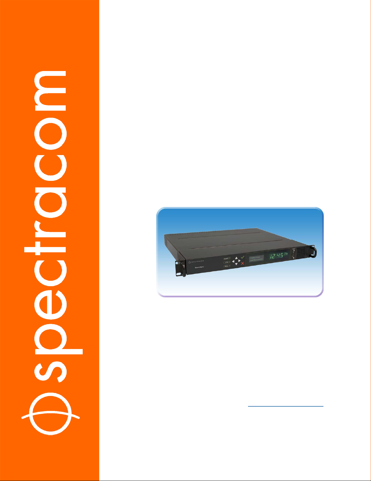
Product Description
The Chapter presents an overview of the SecureSync Time and Frequency Synchronization System, its capabilities, main technical features and specifications.
The following topics are included in thisChapter:
1.1 Getting Started 2
1.2 SecureSync Introduction 2
1.3 SecureSync Front Panel 3
1.4 Unit Rear Panel 7
1.5 Option Cards 8
1.6 The SecureSync Web UI 18
1.7 Specifications 22
1.8 Regulatory Compliance 27
CHAPTER 1
CHAPTER 1 • SecureSync User Reference Guide
1
Page 18
1.1 Getting Started
1.1 Getting Started
Welcome to the SecureSync User Reference Guide.
Where to start:
First-time users: "SecureSync Introduction" below.
Users with some knowledge of Time and Frequency Servers: "Overview" on page30.
If your unit is up and running and you want to change a setting: "Managing Time" on
page145, or "System Administration" on page235.
1.2 SecureSync Introduction
SecureSync®is a security-hardened 1-rack unit network appliance designed to meet rigorous
network security standards and best practices. It ensures accurate timing through multiple references, tamper-proof management, and extensive logging. Robust network protocols are used
to allow for easy but secure configuration. Features can be enabled or disabled based on your
network policies. Installation is aided by DHCP (IPv4), AUTOCONF (IPv6), and a front-panel
keypad and LCD display.
The unit supports multi- constellation GNSS input (SAASM GPS receivers, supporting L1/L2,
available for authorized users and required for the US DoD are available), IRIG input and
other input references. The unit is powered by AC on an IEC60320 connector. DC power as
back-up to AC power, or as the primary input power source, is also available.
SecureSync combines Spectracom’s precision master clock technology and secure network-centric approach with a compact modular hardware design to bring you a powerful time and frequency reference system at the lowest cost of ownership. Military and commercial applications
alike will benefit from its extreme reliability, security, and flexibility for synchronizing critical
operations.
An important advantage of SecureSync is its unique rugged and flexible modular chassis that
can be configured for your specific needs. Built-in time and frequency functions are extended
with up to six input/output modules.
You can choose from a variety of configurable option cards, each with an assortment of
input/output timing signal types and quantity, including additional 1PPS, 10 MHz, timecode
(IRIG, ASCII, HAVE QUICK), other frequencies (5MHz, 2.048MHz, 1.544MHz, 1MHz), Precision Timing Protocol (PTP) input/output, multi-Gigabit Ethernet (10/100/1000Base-T),
2
CHAPTER 1 • SecureSync User Reference Guide Rev. 26
Page 19

telecom T1/E1 data rates and multi-network NTP, allowing SecureSync to be customized for
your exact requirements.
A variety of internal oscillators is available, depending on your requirements for holdover capability and phase noise.
Note: Some of the features described are not available on all SecureSync vari-
ants.
1.2.1 SecureSync's Inputs and Outputs
SecureSync provides multiple outputs for use in networked devices and other synchronized
devices. A 1-Pulse-Per-Second (1PPS) output acts as a precise metronome, counting off seconds
of System Time in the selected timescale (such as UTC, TAI or GPS). A 10MHz frequency reference provides a precise, disciplined signal for control systems and transmitters.
SecureSync's outputs are driven by its inputs – most notably, Global Navigation Satellite System (GNSS), or IRIG signal generators and other available input references. GNSS-equipped
SecureSyncs can track up to 72 GNSS satellites simultaneously and synchronize to the satellite’s
atomic clocks. This enables SecureSync-equipped computer networks to synchronize anywhere
on the planet.
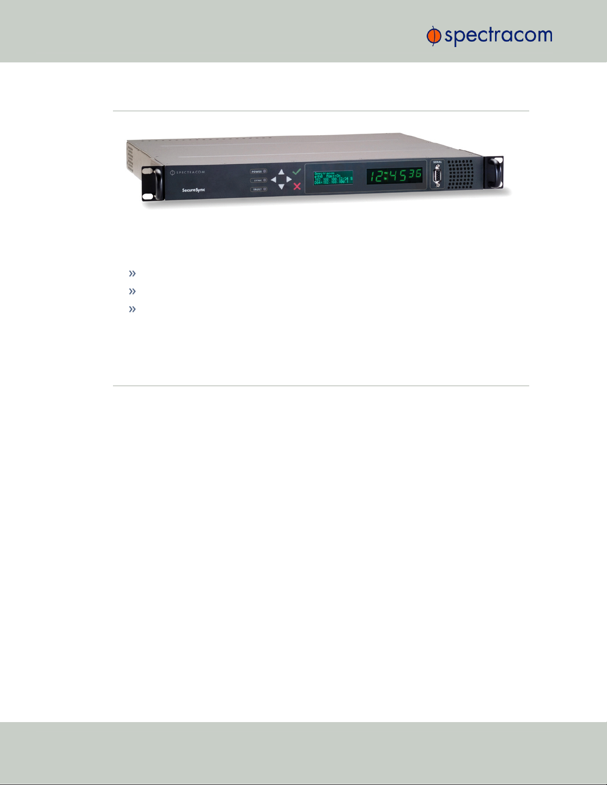
1.3 SecureSync Front Panel
1.3 SecureSync Front Panel
The front panel of a SecureSync unit consists of:
three separate illuminated status LEDs
a front panel control keypad
an LED time display
an LCD information display
an RS-232 serial interface
and a temperature controlled cooling fan.
The LCD information display is configurable using the SecureSync web user interface (also
referred to as the “Web UI”) or the front panel controls. Display options include status or position information, time, date, DOY (Day of Year), GNSS information, as well as network settings and SAASM key status (available with the SAASM GPS receiver option only). The RS-232
serial interface and the front panel controls provide a means of configuring the unit’s network
settings and perform other functions without requiring access to the Web UI.
SecureSync units with the SAASM GPS receiver option module installed also have an encryption key fill connector and key zeroize switch on the left-hand side of the front panel.
CHAPTER 1 • SecureSync User Reference Guide Rev. 26
3
Page 20
1.3 SecureSync Front Panel
Figure 1-1: SecureSync front panel layout (SAASM version)
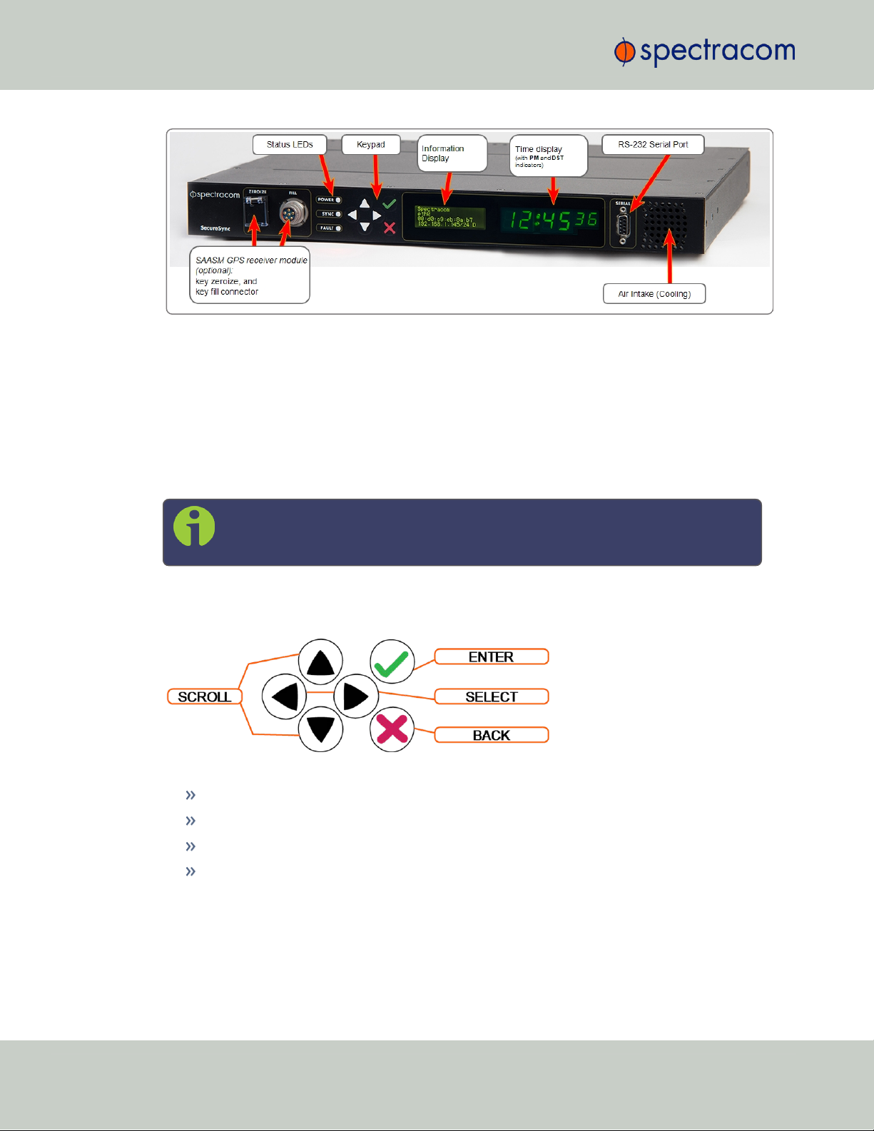
1.3.1 Front Panel Keypad, and Display
To simplify operation and to allow local access to SecureSync, a keypad and a 4-line LCD
information display are provided on the front panel of the unit.
The front panel keypad and display can be used to configure basic network settings e.g., en/disabling DHCP, or setting an IP address and subnet mask.
Note: If the keypad be locked, see "Troubleshooting – Keypad Is Locked" on
page341.
1.3.1.1 Using the Keypad
The functions of the six keys are:
tu arrow keys: Navigate to a menu option (will be highlighted)
pq arrow keys: Scroll through parameter values in edit displays
ü ENTER key: Select a menu option, or load a parameter when editing
Ò BACK key: Return to previous display or abort an edit process
1.3.1.2 Navigating the Front Panel Display
After power initialization, press any key to go to the “Home” display. As shown in the illustration "Front panel menu tree" on the facing page, several status and setup displays are
4
CHAPTER 1 • SecureSync User Reference Guide Rev. 26
Page 21
1.3 SecureSync Front Panel
accessible from the main “Home” menu. To navigate through the menus, use the arrow keys to
highlight a selection and then press the ENTER button.
The main menu options and their primary functions are as follows:
Display: Used to configure the information display
Clock:Displaying and setting of the current date and time
System:Displaying version info, system halt and reboot, reset spadmin password
Netv4:Network interface configuration
Lock: Locks the front panel keypad to prevent inadvertent operation.
Front Panel Display: Menu Tree
The illustration below shows how the menu is organized, and which functions can be accessed
via the front panel (i.e. without using the Web UI):
Figure 1-2: Front panel menu tree
To modify a parameter:
Highlight the menu option and press the ENTER button.
“O” stands for current old setting, and “N” is the new setting.
You can only change the “N” setting.
Use the UP and DOWN arrow keys to scroll through all possible parameter values.
To edit a sequence of numbers:
CHAPTER 1 • SecureSync User Reference Guide Rev. 26
5
Page 22

LED Label Activity/Color Description
POWER
Off Both AC, and DC input power are disconnected.
OR: The unit's AC input switch is turned OFF, and DC input is not
present.
On/solid
green
AC and/or DC Power are supplied; the unit detects all power
inputs.
Red
The unit is configured for two power inputs, but detects only one
power input. OR:Detects a power configuration error.
Green
& blinking
orange
1/sec.
Power Error — general power configuration fault.
SYNC
Red
Time Sync Alarm:
1) The unit has powered up, but has not yet achieved synchronization with its inputs.
2) The unit was synchronized to its selected input references, but
has since lost all available inputs (or the inputs were declared
invalid) and the Holdover period has since expired.
Solid
green
The unit has valid time and 1PPS reference inputs present and is synchronized to its reference.
Orange
The unit is in Holdover Mode: It was synchronized to its selected
input references, but has since lost all available inputs (or the inputs
are not declared valid).The time and frequency outputs will remain
useable until the Holdover period expires.
1.3 SecureSync Front Panel
Use the LEFT and RIGHT arrow keys to select other digits. Once the desired parameter is
displayed, press ENTER to make the new value the current ("O") value. You will be asked
to confirm the setting change. Press ENTER to accept or BACK to cancel the parameter
change.
All entered values are stored in the unit's non- volatile memory and will be restored after a
power cycle.
1.3.2 Status LEDs
Three Status LEDs (see "SecureSync front panel layout (SAASM version)" on page4), located
on the unit's front panel, indicate SecureSync's current operating status:
POWER: Green, always on while power is applied to the unit
SYNC: Tri-color LED indicates the time data accuracy
FAULT: Two-color, three-state LED, indicating if any alarms are present.
At power up, the unit automatically performs a brief LED test run during which all three LEDs
are temporarily lit.
Table 1-1:
Front panel status indications
6
CHAPTER 1 • SecureSync User Reference Guide Rev. 26
Page 23
LED Label Activity/Color Description
FAULT
Off No alarm conditions are currently active.
Blinking
orange
A GNSS antenna alarm has been asserted and is currently active.
A short or open circuit has been detected in the GNSS antenna
cable. The light will automatically turn off once the alarm condition
clears.
To troubleshoot this condition, see
"Troubleshooting via Web
UI Status Page" on page338
.
Solid
orange
A Minor Alarm condition (other than an antenna problem alarm)
has been asserted and is currently active.
To troubleshoot this condition, see
"Minor and Major Alarms"
on page335
.
Red
A Major Alarm condition has been asserted and is currently active.
To troubleshoot this condition, see
"Minor and Major Alarms"
on page335
.
1.4 Unit Rear Panel
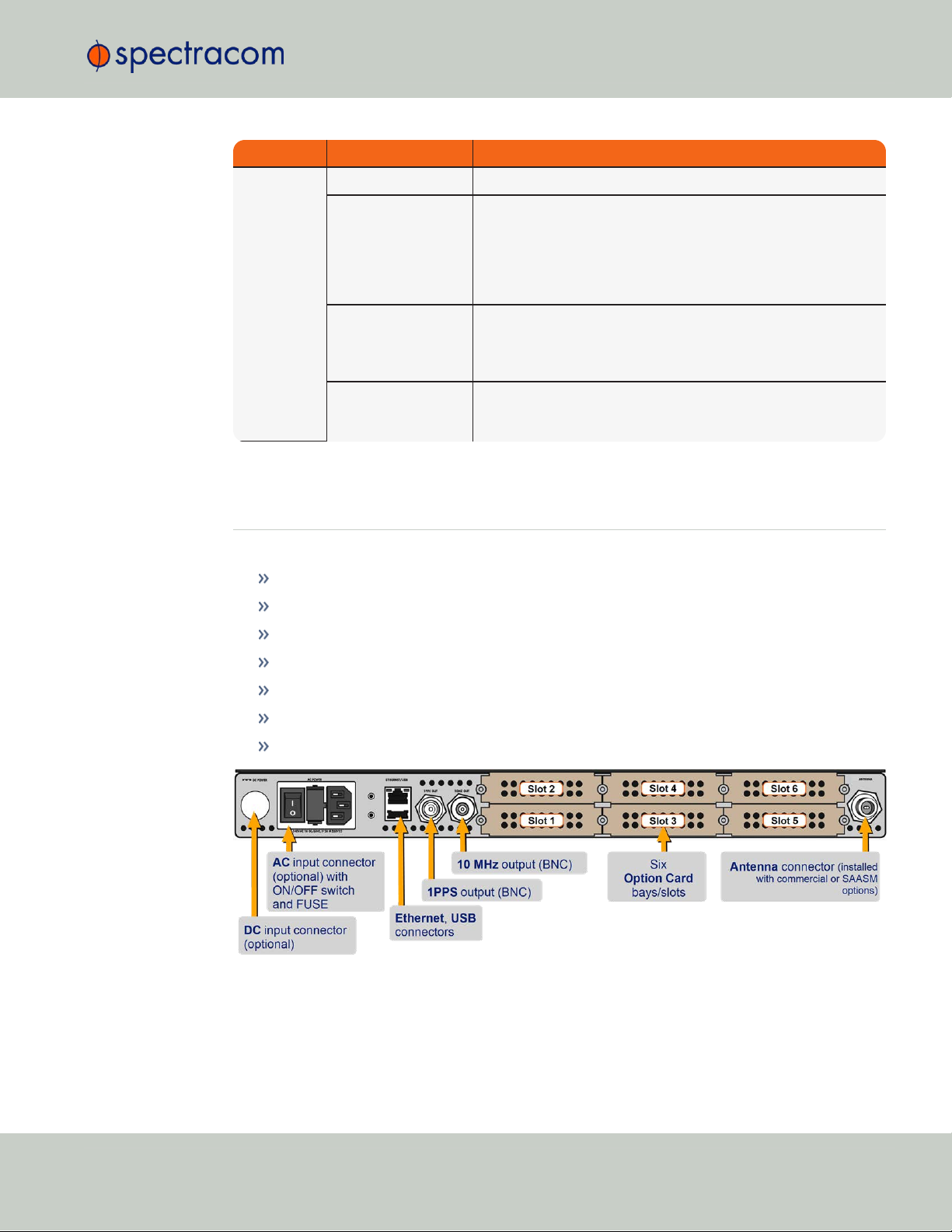
1.4 Unit Rear Panel
The SecureSync rear panel accommodates the connectors for all input and output references.
Optional AC connection for the power input
Optional DC power connector
Ethernet and USB connections
1PPS output
10 MHzoutput
Six bays for option cards
One optional antenna connector.
Figure 1-3: Standard rear panel
Typically, option cards will be installed at the factory. Should you purchase an extra option
card at a later point, you will need to populate the next vacant slot, observing the numerical
CHAPTER 1 • SecureSync User Reference Guide Rev. 26
7
Page 24
LED State Meaning
Orange
On
Off
LAN Activity detected
No LAN traffic detected
Green
On
Off
LAN Link established, 10 or 100 Mbps
No link established
1.5 Option Cards
order shown above. However, not all cards can be installed in all slots. Your local Spectracom
Sales Office will gladly assist you with the optimal option cards selection for your application.
The DC Power port connector is only installed if your unit was ordered with a DC input power
option. Other optional input/output connectors depend on the installed option cards.
Note: DC input power does not have an ON/OFF switch.
The ACPower connector is the input for the ACpower and provides an ACpower
ON/OFF switch. This connector assembly is only installed if SecureSync was ordered
with AC input power option.
The Ethernet connector provides an interface to the network for NTP synchronization and
to obtain access to the SecureSync product Web UI for system management. It has two
small indicator lamps, “Good Link” (green LED), and “Activity” (orange LED). The “Good
Link” light indicates a connection to the network is present. The “Activity” light will illuminate when network traffic is detected.
Table 1-2:
Ethernet status indicator lights
The USB connector is reserved for future expansion.
The 1PPS BNC connector offers a once-per-second square-wave output signal. The 1PPS
signal can be configured to have either its rising or falling edge to coincide with the system’s on-time point.
The 10 MHz BNC connector provides a 10 MHz sine-wave output signal.
The optional ANTENNA connector is a type “N” connector for the GNSS input from
your GNSS antenna via a coax cable. This connector will only be present if the standard GNSS receiver, or the optional SAASM GPS receiver module are installed.
1.5 Option Cards
Option Cards are circuit boards that can be installed into a SecureSync unit in order to add
input and output functionality. Installation is normally done in the factory when the unit is built.
Many cards, however, can be retrofitted in the field by qualified customer personnel (see
"Option Card Field Installation Instructions" on page351).
8
CHAPTER 1 • SecureSync User Reference Guide Rev. 26
Page 25

Caution: NEVER install an option card from the back of the unit, ALWAYS from
the top. It is therefore necessary to remove the top cover of the main chassis (housing).
Input and outputs can be categorized by:
Communication direction:
Input
Output
Signal type:
Frequency: 1/5/10/[programmable]MHz
Wave form (square, sinus)
1PPS
TTS
1.5 Option Cards
CTCSS
Signal protocol:
ASCII time code
IRIG
STANAG
Have Quick
E1/T1 data
Telecom timing, etc.
Ethernet (NTP, PTP)
Time code I/O
Alarm out, etc.
Functionality:
Networking card (incl. NTP, PTP)
Time code I/O
Alarm output
Special functionality e.g., revertive selector, bidirectional communication
Connector type:
BNC
DB-9/25
Terminal block
CHAPTER 1 • SecureSync User Reference Guide Rev. 26
9
Page 26
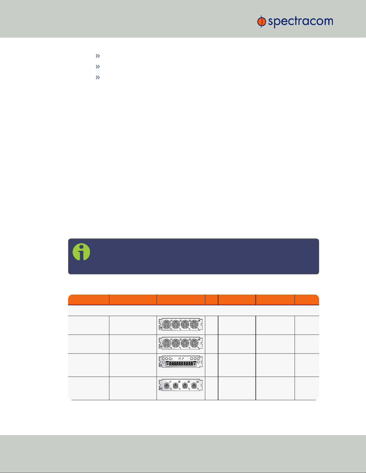
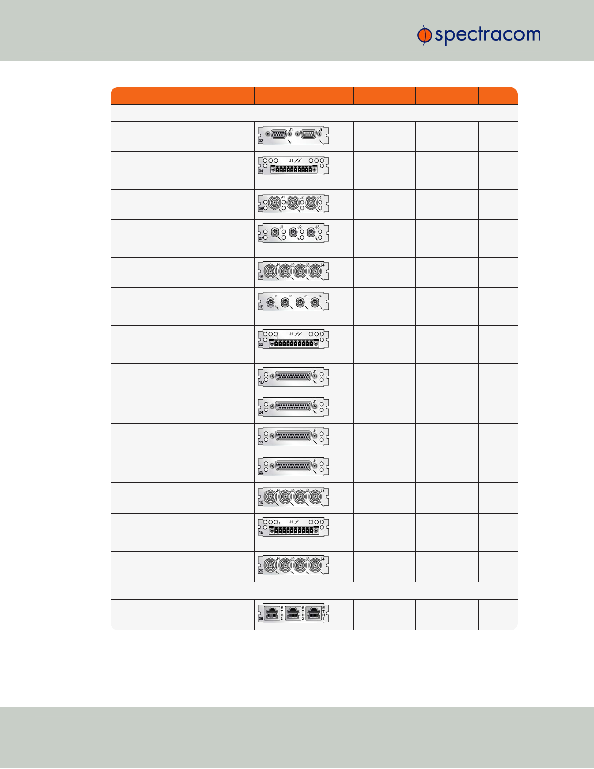
Function Web UI Name Illustration ID* Inputs Outputs Conn.'s
Time and Frequency Cards
Quad 1PPS out
(TTL)
1PPS Out BNC
18
0 1PPS, TTL (4x) BNC
(4x)
Quad 1PPS out
(10 V)
1PPS Out 10V
19
0 1PPS, 10 V
(4x)
BNC
(4x)
Quad 1PPS out
(RS-485)
1PPS Out, RS-485
21
0 1PPS, RS-485
(4x)
Terminal
block,
10-pin
Quad 1PPS out
(fiber optic)
1PPS Out, Fiber
2B
0 1PPS, F/O
(4x)
ST Fiber
optic
(4x)
1.5 Option Cards
RJ-12/45
SFP
ST fiber optic
To visually identify an option card installed in your unit, or to obtain an overview which option
cards are available for SecureSync, see "Option Cards Overview" below.
To obtain detailed information on a specific option card, using its ID number, see "Option Card
Identification" on page13.
To locate option card topics in this manual by their heading or functionality, see "Option Cards"
on page345. This Chapter also includes information on field installation and Web UI func-
tionality.
To visually identify a connector type, see "Option Card Connectors" on page16.
1.5.1 Option Cards Overview
The table below lists all SecureSync option cards available at the time of publication of this document, sorted by their function.
The table column (see table below) WebUI Name refers to the names under which the cards
installed in a SecureSync unit are listed in the INTERFACES > OPTION CARDS drop-down menu.
Detailed specifications and configuration assistance for every card can be found in the
APPENDIX. To quickly access the APPENDIX topic for your option card(s), you may use the
hyperlinks in table "Option cards listed by their ID number" on page14.
Note: * Every option card has a unique 2-digit ID number located on its cover
plate, and in the center column of the table below. The complete Spectracom Part
Number for option cards is 1204-xx (e.g., 1204-18).
Table 1-3:
Option cards identification
10
CHAPTER 1 • SecureSync User Reference Guide Rev. 26
Page 27
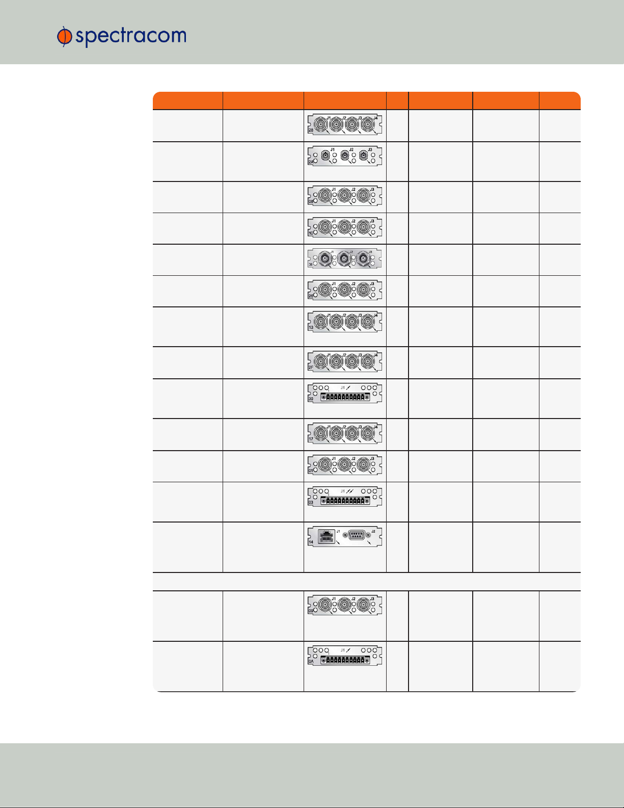
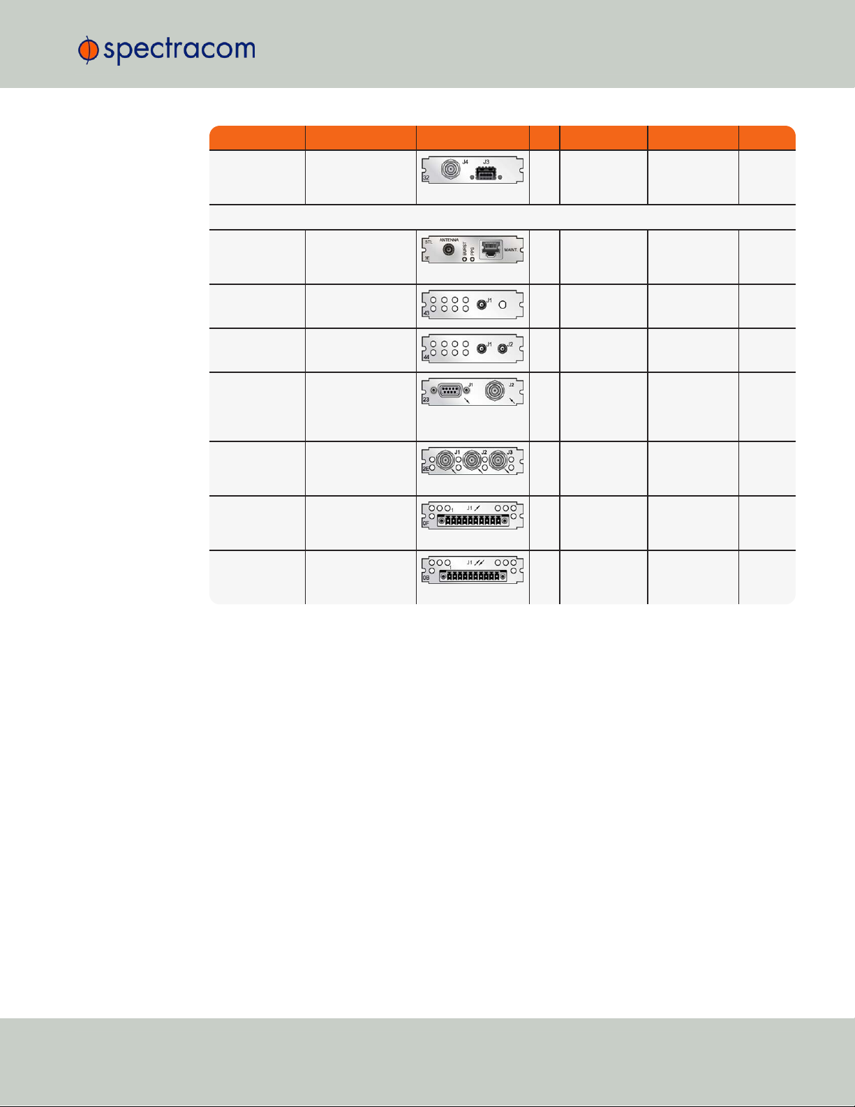
Function Web UI Name Illustration ID* Inputs Outputs Conn.'s
1in/3out 1PPS
(TTL [BNC])
1PPS/Frequency
RS-485
28
1PPS (1x) 1PPS (3x) BNC
(4x)
1in/2out
1PPS/freq
(fiber optic)
1PPS In/Out,
Fiber
2A
1PPS (1x) 1PPS (2) ST Fiber
optic
(3x)
5MHz out 5MHz Out
08
0 5MHz (3x) BNC
(3x)
10 MHz out 10 MHz Out
1C
0 10 MHz (3x) BNC
(3x)
10 MHz out 10 MHz Out
38
0 10 MHz (3x) TNC
(3x)
1MHz out 1MHz Out
26
0 1MHz (3x) BNC
(3x)
Progr. frequ.
out (Sine
Wave)
Prog Freq Out,
Sine
13
0 progr. clock,
sine (4x)
BNC
(4x)
Progr. frequ out
(TTL)
Prog Freq Out, TTL
2F
0 progr. clock,
TTL/sq. (4x)
BNC
(4x)
Prog frequ out
(RS-485)
Prog Freq Out, RS485
30
0 progr. clock,
RS-485 (4x)
Terminal
block,
10-pin
Square Wave
out
Square Wave
Out, BNC
17
0 square wave,
TTL (4x)
BNC
(4x)
1PPS in/out +
frequ. in
1PPS/Frequency
BNC
01
Var. frequ. +
1PPS
1PPS (TTL) BNC
(3x)
1PPS in/out +
frequ. in
1PPS/Frequency
RS-485
03
10 MHz +
1PPS
1PPS Terminal
block,
10-pin
CTCSS, Data
Sync/Clock
Simulcast
14
0 data clock,
CTCSS frequ.,
1PPS, 1alarm
(3x)
RJ-12 &
DB-9
Telecom Timing Cards
E1/T1 data,
75Ω
E1/T1 Out BNC
09
0 1.544/2.048
MHz (1x)
unbal. E1/T1
(2x)
BNC
(3x)
E1/T1 data,
100/120Ω
E1/T1 Out Terminal
0A
0 1.544/2.048
MHz (1x)
unbal. E1/T1
(2x)
Terminal
block,
10-pin
1.5 Option Cards
CHAPTER 1 • SecureSync User Reference Guide Rev. 26
11
Page 28
Function Web UI Name Illustration ID* Inputs Outputs Conn.'s
Time Code Cards
ASCII Time
Code RS-232
ASCII Timecode
RS-232
02
1 RS-232 (1x) DB-9
(2x)
ASCII Time
Code RS-485
ASCII Timecode
RS-485
04
1 1 Terminal
block,
10-pin
IRIG BNC IRIG In/Out BNC
05
1 2 BNC
(3x)
IRIG Fiber
Optic
IRIG In/Out, Fiber
27
1 2 ST Fiber
optic
(3x)
IRIG out, BNC IRIGOut BNC
15
0 4 BNC
(4x)
IRIG out, fiber
optic
IRIG Out, Fiber
1E
0 4 ST Fiber
optic
(4x)
IRIG out, RS485
IRIGOut, RS-485
22
0 4 Terminal
block,
10-pin
STANAG input STANAG In
1D
2x 1x DB-25
(1x)
STANAG in,
isol.
STANAG In, Isolated
24
2x 1x DB-25
(1x)
STANAG out STANAG Out
11
0 2x STANAG,
1x 1PPS
DB-25
(1x)
STANAG out,
isol.
STANAG Out,
Isolated
25
0 2x STANAG,
1x 1PPS
DB-25
(1x)
HAVE QUICK
out BNC
HAVE QUICK
Out, BNC
10
0 4 (TTL) BNC
(4x)
HAVE QUICK
out RS-485
HAVE QUICK
Out, RS-485
1B
0 4 Terminal
block,
10-pin
HAVE QUICK HAVE QUICK
29
1 3 BNC
(4x)
Networking Cards
Gigabit Ethernet
Gb Ethernet
06
(3, OR output) (3, OR input) RJ-45
(3x)
1.5 Option Cards
12
CHAPTER 1 • SecureSync User Reference Guide Rev. 26
Page 29
Function Web UI Name Illustration ID* Inputs Outputs Conn.'s
1Gb PTP:
Master only
Gb PTP
32
0 1PPS (1x
BNC), SFP
(1x)
BNC
(1x),
SFP (1x)
Communication and Specialty Cards
STL (Satellite
Time and Location)
STL
3E
Satellite, Eth.
(Maintenance)
0 SMA,
RJ45
Single GNSS GNSS Receiver
43
1 0 SMA
Dual GNSS Dual GNSS
Receiver
44
2 0 SMA
(2x)
Event in, Broadcast out
Event Broadcast
23
BNC: Event
trigger
DB-9: Event
broadcast
DB-9 +
BNC
(1x
each)
Revertive
Selector ("Failover")
n/a
2E
Frequ. or 1
PPS: (2x)
Frequ. or 1PPS
(1x)
BNC
(3x)
Alarm Relay
Out
Relay Output
0F
0 Relay Out (3x) Terminal
block,
10-pin
Bidir. Communication
RS-485 Comm
0B
Yes Yes Terminal
block,
10-pin
1.5 Option Cards
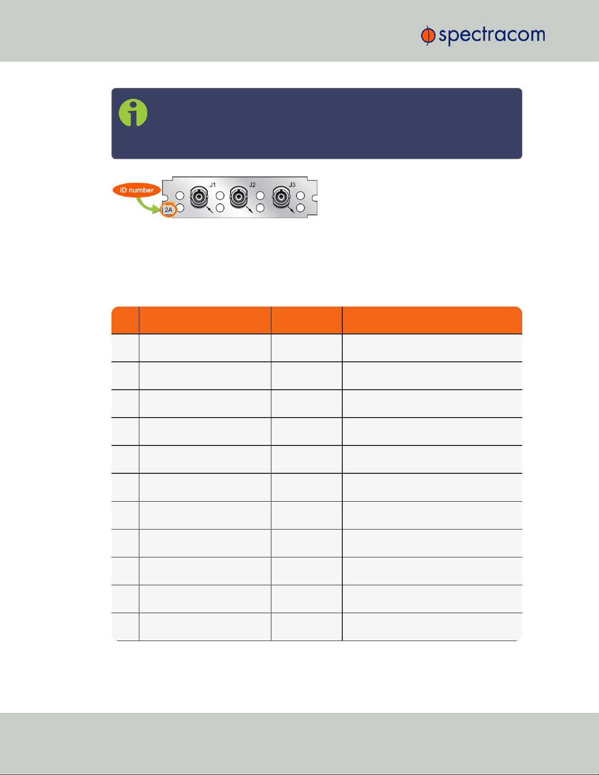
1.5.2 Option Card Identification
There are several ways to identify which option card(s) are installed in your SecureSync unit:
a.
Using the Web UI, navigate to the INTERFACES > OPTION CARDS drop-down menu, and
compare the list displayed in your UI with the table "Option cards identification" on
page10.
1.5.2.1 Option Card Identification by ID/Part Number
b.
If you have physical access to your SecureSync unit, inspect its rear panel, and compare
the 2-digit ID number printed in the lower left-hand corner on each option card with the
table below.
If you are looking for information specific to a particular option card, the table below can help
you find this information in this User Reference Guide.
CHAPTER 1 • SecureSync User Reference Guide Rev. 26
13
Page 30
Card
ID*
Card Name Name in UI See ...
01 1PPS/freq input (TTL levels) mod-
ule
1PPS/Frequency
BNC
"1PPS In/Out, 10MHz In [1204-01, 03]" on page377
02 ASCII Time Code module (RS-
232)
ASCII Timecode
RS-232
"ASCII Time Code In/Out [1204-02, 04]" on page455
03 1PPS/freq input (RS-485 levels)
module
1PPS/Frequency
RS-485
"1PPS In/Out, 10MHz In [1204-01, 03]" on page377
04 ASCII Time Code module (RS-
485)
ASCIITimecode
RS-485
"ASCII Time Code In/Out [1204-02, 04]" on page455
05 IRIG module, BNC (1 input, 2
outputs)
IRIG In/Out
BNC
"IRIG In/Out [1204-05, -27]" on
page415
06 Gigabit Ethernet module (3 ports) Gb Ethernet
"Gigabit Ethernet [1204-06]" on
page467
08 5 MHz output module (3 outputs) 5 MHz Out
"Frequency Out [1204-08, -1C, -26, 38]" on page384
09 T1-1.544 (75 Ω) or E1-2.048 (75
Ω) module
E1/T1 Out BNC
"T1/E1 Out [1204-09, -0A]" on
page404
0A T1-1.544 (100 Ω) or E1-2.048
(120 Ω) module
E1/T1 Out Terminal
"T1/E1 Out [1204-09, -0A]" on
page404
0B Bidirectional Communication
module
RS-485 Comm
"Bi-Directional Communication, RS-485
[1204-0B]" on page509
0F Alarm module Relay Output
"Alarm Relay Out [1204-0F]" on
page495
1.5 Option Cards
Note: * Every option card has a 2-digit identification (ID) number that can be
found in the corner of its cover plate, and in the table below. The ID number is
comprised of the two center digits of your option card's Spectracom Part Number: 1204-0180-0600.
Figure 1-4: Option Card ID number
The table lists all option cards available at the publication date of this documentation, sorted by
their ID number. Locate the option card ID number on its cover plate, and follow the cor-
responding hyperlink in the right-hand column.
Table 1-4:
Option cards listed by their ID number
14
CHAPTER 1 • SecureSync User Reference Guide Rev. 26
Page 31

Card
ID*
Card Name Name in UI See ...
10 HaveQuick output module (TTL) HAVE QUICK
Out, BNC
"HAVE QUICK Out [1204-10, -1B]" on
page443
11 STANAG output module STANAG Out
"STANAG Out [1204-11, -25]" on
page428
12 10/100 Mb PTP module (EOL) PTP "PTP Master/Slave [1204-12]" on page1
13 Programmable Frequency Out-
put module (Sine Wave)
Prog Freq Out,
Sine
"Programmable Frequency Out [120413, -2F, -30]" on page387
14 CTCSS, Data Sync/Clock mod-
ule ("Simulcast")
Simulcast
"Simulcast (CTCSS/Data Clock) [120414]" on page396
15 IRIG module, BNC (4 outputs) IRIG Out BNC
"IRIG Out [1204-15, -1E, -22]" on
page409
17 Square Wave (TTL) output mod-
ule
Sq Wv Out,
BNC
"Programmable Square Wave Out
[1204-17]" on page392
18 Quad 1 PPS output module (TTL) 1PPS Out BNC
"1PPS Out [1204-18, -19, -21, -2B]" on
page367
19 Quad 1 PPS output module (10V)1PPS Out 10V
"1PPS Out [1204-18, -19, -21, -2B]" on
page367
1B HaveQuick output module (RS-
485)
HAVEQUICK
Out, RS-485
"HAVE QUICK Out [1204-10, -1B]" on
page443
1C 10 MHz output module (3 out-
puts)
10 MHz Out
"Frequency Out [1204-08, -1C, -26, 38]" on page384
1D STANAG input module STANAG In
"STANAG In [1204-1D, -24]" on
page435
1E IRIG module, Fiber Optic (4 out-
puts)
IRIGOut, Fiber
"IRIG Out [1204-15, -1E, -22]" on
page409
21 Quad 1 PPS output module (RS-
485 [terminal block])
1PPS Out, RS485
"1PPS Out [1204-18, -19, -21, -2B]" on
page367
22 IRIG module, RS-485 (4 outputs) IRIG Out, RS-
485
"IRIG Out [1204-15, -1E, -22]" on
page409
23 Event Broadcast module Event Broadcast
"Event Broadcast [1204-23]" on
page501
24 STANAG isolated input module STANAG In, Isol-
ated
"STANAG In [1204-1D, -24]" on
page435
25 STANAG isolated output module STANAG Out,
Isolated
"STANAG Out [1204-11, -25]" on
page428
26 1 MHz output module (3 outputs) 1MHz Out
"Frequency Out [1204-08, -1C, -26, 38]" on page384
27 IRIG module, Fiber Optic (1
input, 1 outputs)
IRIG In/Out,
Fiber
"IRIG In/Out [1204-05, -27]" on
page415
1.5 Option Cards
CHAPTER 1 • SecureSync User Reference Guide Rev. 26
15
Page 32

Card
ID*
Card Name Name in UI See ...
28 1-in/3-out 1 PPS module (TTL
[BNC])
1PPS/Frequency
RS-485
"1PPS In/Out [1204-28, -2A]" on
page372
29 1-in/3-out HaveQuick module
(TTL [BNC])
HAVEQUICK
"HAVE QUICK In/Out [1204-29]" on
page449
2A 1-in/3-out 1 PPS module (Fiber
Optic)
1PPS In/Out,
Fiber
"1PPS In/Out [1204-28, -2A]" on
page372
2B Quad 1 PPS output module
(Fiber Optic)
1PPS Out, Fiber
"1PPS Out [1204-18, -19, -21, -2B]" on
page367
2F Programmable Frequency Out-
put module (TTL)
Prog Freq Out,
TTL
"Programmable Frequency Out [120413, -2F, -30]" on page387
2E Revertive Selector module ("Fail-
over")
n/a
"Revertive Selector Card [1204-2E]" on
page500
3E STL input module STL
"STL Option Module [1204-3E]" on
page486
30 Programmable Frequency Out-
put module (RS-485)
Prog Freq Out,
RS-485
"Programmable Frequency Out [120413, -2F, -30]" on page387
32 1Gb PTP module Gb PTP
"PTP Grandmaster [1204-32]" on
page469
38 10 MHz output module (3 x TNC
outputs)
10 MHz Out
"Frequency Out [1204-08, -1C, -26, 38]" on page384
43 Single GNSS module GNSS Receiver
"GNSS Receiver [1204-43, -44]" on
page485
44 Dual GNSS module Dual GNSS
Receiver
"GNSS Receiver [1204-43, -44]" on
page485
Connector Illustration Electr. Signals Timing signals
BNC Differential TTL xV, sine wave, programm.
square wave, AM sine wave, DCLS
1PPS, frequency,
IRIG, HAVE
QUICK,
PTP
ST Fiber Optic AM sine wave, DCLS IRIG, 1PPS
1.5 Option Cards
1.5.3 Option Card Connectors
The table below lists the connector types used in SecureSync option cards.
Table 1-5:
Option card connectors
16
CHAPTER 1 • SecureSync User Reference Guide Rev. 26
Page 33

Connector Illustration Electr. Signals Timing signals
Terminal Block
[
Recommended mating connector:
Phoenix Contact, part
no. 1827787]
RS-485 1PPS, frequency,
ASCIItime code,
IRIG, HAVEQUICK,
Alarm, T1/E1
DB-9 RS-232, RS-485 ASCIItime code,
GPS NMEA, data
clocks,
CTCSS frequency,
1PPS, Alarm signal
DB-25 Differential TTL xV, RS-485 STANAG
RJ-12 RS-485 data clock, CTCSS
frequency,
1PPS, Alarm
RJ-45 Gb-Ethernet PTP timing signal
SFP Ethernet PTP timing signal
SMA RF, differential TTL xV, sine wave, programm.
square wave, AM sine wave, DCLS
1PPS, frequency
1.5 Option Cards
CHAPTER 1 • SecureSync User Reference Guide Rev. 26
17
Page 34

1.6 The SecureSync Web UI
1.6 The SecureSync Web UI
SecureSync has an integrated web user interface (referred to as "WebUI" throughout this documentation) that can be accessed from a computer over a network connection, using a standard
web browser. The WebUI is used to configure the unit, and for status monitoring during everyday operation.
Note: An integrated Command-Line Interpreter interface (CLI) allows the use of a
subset of commands that are integrated into the Web UI.
The minimum browser requirements for the Web UI are: Internet Explorer®9 or higher,
Firefox®, or Chrome®.
Note: Should it ever be necessary, you can restore SecureSync's configuration to
the factory settings at any time. See "Resetting the Unit to Factory Configuration"
on page322.
1.6.1 The Web UI HOME Screen
Note: Screens displayed in this manual are for illustrative purposes. Actual
screens may vary depending upon the configuration of your product.
The HOME screen of the SecureSync web user interface ("Web UI") provides comprehensive
status information at a glance, including:
vital system information
current status of the references
key performance/accuracy data
major log events.
The HOMEscreen can be accessed from anywhere in the Web UI, using the HOMEbutton in
the Primary Navigation Bar:
18
CHAPTER 1 • SecureSync User Reference Guide Rev. 26
Page 35

The Primary Navigation Bar provides access to all menus:
HOME: Return to the HOME screen (see above)
1.6 The SecureSync Web UI
INTERFACES: Access the configuration pages for …
… references (e.g., GNSS, NTP)
… outputs (e.g. 10 MHz, PPS, NTP) and
… installed input/output option cards.
MANAGEMENT: Access the NETWORK setup screens, and OTHER setup screens e.g., to
configure Reference Priorities, System Time, and the Oscillator.
TOOLS: Opens a drop-down menu for access to the system maintenance screens and sys-
tem logs.
HELP/MONITORING: Provides Spectracom Service Contact Information and high-level
system configurations you may be required to furnish when contacting Spectracom Service. (If the optional TimeKeeper license is installed, this button will open the TimeKeeper
Monitoring menu. See also "Status Monitoring with TimeKeeper" on page231.)
1.6.2 The INTERFACES Menu
The INTERFACES menu on the Main screen provides access to SecureSync's:
External REFERENCES e.g., the GNSS reference input
Detected OUTPUTS, such as 10 MHz and 1PPS
Installed OPTION CARDS.
CHAPTER 1 • SecureSync User Reference Guide Rev. 26
19
Page 36

1.6 The SecureSync Web UI
Clicking on any of the line items will open a status screen, providing real-time information on
the selected interface e.g., availability, performance data and events history.
To configure settings for the selected interface, click the GEAR icons or buttons provided on
most of the status screens. Icons like the INFO symbol provide access to more detailed status
information and history data.
Note: Many of the interfaces can be accessed through different menu items e.g.,
an optional output will be available under the OPTION CARDS menu and the
OUTPUTS menu.
The headings of each of the INTERFACES drop-down menus (white on orange) open overview
status screens for the respective menu items.
1.6.3 The Configuration MANAGEMENT Menu
The MANAGEMENT menu on the Web UI's Main screen provides access to SecureSync's configuration screens and settings.
20
On the left side, under NETWORK, the following standard setup screens can be found:
Network Setup
General Setup
HTTPS Setup
CHAPTER 1 • SecureSync User Reference Guide Rev. 26
Page 37

SSH Setup
SNMP Setup
NTP Setup
PTP Setup
PeerD Setup.
Under OTHER, you can access non-network related screens:
Authentication: Manage user accounts, Security Policy, LDAP Setup, RADIUS setup, Login
Preference and Remote Servers. Change My Password is also available.
Reference Priority: Define the order of priority for timing inputs.
Notifications: Configure the notifications triggered by SecureSync’s events. A notification
can be a combination of a mask alarm and/or SNMP Trap and/or email.
Time Management: Manage the Local Clock, UTC Offset, DST Definition and Leap
Second information.
Front Panel: Configure the appearance of the SecureSync front panel display and
keypad.
1.6 The SecureSync Web UI
Log Configuration: Manage the system logs.
Disciplining: Manage oscillator disciplining.
Change My Password: Configure the admin password.
1.6.4 The TOOLS Menu
The TOOLS menu on the Web UI's Main screen provides access to:
The System Upgrade screen
System and network monitoring screens
Miscellaneous system administration screens
Log screens
CHAPTER 1 • SecureSync User Reference Guide Rev. 26
21
Page 38

1.7 Specifications
1.7 Specifications
The specifications listed below apply to the SecureSync standard model, i.e. not including any
option cards, and are based on “normal” operation, with SecureSync synchronized to valid
Time and 1PPS input references (in the case of GNSS input, this is with the GNSS receiver operating in Stationary mode).
Specifications for the available option cards are provided in their corresponding topics;see
"Option Cards Overview" on page10.
1.7.1 Input Power
AC power source:
100 to 240 VAC, 50/60 Hz, ±10 % and
100-120 VAC400 Hz, ±10% via an IEC 60320 connector (power cord included)
DC input (option):
12-17 VDC-15%, +20%, or
Maximum power draw:
1.7.1.1 Fuses
Type: T 2A L 250V
Model:
Number: 2 (two) per unit
SecureSync label on rear panel of unit:
21-60 VDC-15%, +20%, secure locking device
TCXO/OCXO oscillator installed: 40 W normal (50 W start-up)
Rubidium (Rb) oscillator installed: 50 W normal (80 W start-up)
Low-Phase Noise (LPN) Rubidium oscillator installed: 52 W normal (85 W start-up)
Spectracom recommends: LITTELFUSE 0213002.MXP
[Spectracom part number: F010R-0002-000 E FUSE,2A,SB,IECSURGE,GLASS]
"AC POWER/F 2A T 250V (2)"
LEGEND:
22
F = Fuse
2A = Current Rating: 2 Ampères
T = Speed: Time Delay (Slow-Blow)
CHAPTER 1 • SecureSync User Reference Guide Rev. 26
Page 39

Caution: Before testing fuses, remove ACpower by disconnecting the AC power
cord.
Note: In the event that the unit does not power up with AC power, these fuses
should be tested.
1.7.2 GNSS Receiver
Model: u-blox M8T
Compatible signals:
1.7 Specifications
L = Breaking Capacity: Low (Glass)
250V = Voltage Rating
(2) = Fuses used: 2 (two)
GPS L1 C/A Code transmissions at 1575.42 MHz
GLONASS L10F transmissions centered at 1602.0 MHz
Galileo E1 B/C transmissions at 1575.42 MHz
BeiDou B1 transmissions centered at 1561.098 MHz
QZSS L1-SAIF transmissions at 1575.42 MHz
Satellites tracked: Up to 72 simultaneously
Update rate: up to 2Hz (concurrent)
Acquisition time: Typically <27seconds from cold start
Antenna requirements: Active antenna module, +5V, powered by SecureSync, 16dB gain min-
imum
Antenna connector: Type N, female
1.7.3 RS-232 Serial Port (Front Panel)
Function: Accepts commands to locally configure the IP network parameters via CLI for initial
unit configuration.
Connector: DB9F, pin assignments conform to EIA/TIA-574, data communication equipment
Character structure: ASCII, 9600 baud, 1 start, 8 data, 1 stop, no parity
1.7.4 10/100 Ethernet Port
Function: 10/100 Base-T, auto-sensing LAN connection for NTP/SNTP and remote management
and configuration, monitoring, diagnostics and upgrade
Connector: RJ-45, Network IEEE 802.3
CHAPTER 1 • SecureSync User Reference Guide Rev. 26
23
Page 40

Oscillator Type
Accuracy to UTC
(1 sigma locked to GPS)
Holdover (constant temp. after 2weeks of GPS lock)
After 4 hours After 24 hours
Low-phase noise Rubidium ±25 ns 0.2 μs 1μs
Rubidium ±25 ns 0.2 μs 1μs
Low-phase noise OCXO ±25 ns 0.5 μs 10 μs
OCXO ±50 ns 1μs 25 μs
TCXO ±50 ns 12 μs 450 μs
1.7 Specifications
1.7.5 Protocols Supported
NTP: NTP Version4 (Installed: Version 4.2.8p8). Provides MD5, Stratum1 through 15 (RFC
5905). Note that NTP Autokey is currently not supported, for more information, see
http://bugs.ntp.org/show_bug.cgi?id=3005.
NTP throughput: ETH0: 7000-7200 NTP requests per second; ETH1-ETH3 (1204- 006-0600
GigabitEthernet option card 1-3): 8800-9000 NTP requests per second. For additional information, please contact Spectracom.
Clients supported: The number of users supported depends on the class of network and the sub-
net mask for the network. A gateway greatly increases the number of users.
TCP/IP application protocols for browser-based configuration and monitoring: HTTP, HTTPS
FTP/SFTP: For remote upload of system logs and (RFC 959)
Syslog: Provides remote log storage (RFCs 3164 and 5424)
SNMP: Supports v1, v2c, and v3
Telnet/SSH: For limited remote configuration
Security features: Up to 32-character password, Telnet Disable, FTP Disable, Secure SNMP,
SNMP Disable, HTTPS/HTTP Disable, SCP, SSH, SFTP.
Authentication: LDAP v2 and v3, RADIUS, MD5 Passwords, NTP Autokey protocol.
1.7.6 1PPS Output
Signal: One pulse-per-second square wave (ext. reference connected to GNSS receiver)
Signal level: TTL compatible, 4.3 V minimum, base-to-peak into 50 Ω
Pulse width: Configurable pulse width (200 ms by default)
Pulse width range: 20 ns to 900 ms
Rise time: <10 ns
Accuracy: Positive edge within ±50 ns of UTC when locked to a valid 1PPS input reference
Connector: BNC female
Table 1-6:
1PPS output accuracies
24
CHAPTER 1 • SecureSync User Reference Guide Rev. 26
Page 41
1.7.7 10 MHz Output
Oscillator Type Accuracy
Low-phase noise Rubidium 1x10
-12
typical 24-hour average locked to GPS
1x10
-11
per day (5x10
-11
per month) typical aging unlocked
Rubidium 1x10
-12
typical 24-hour average locked to GPS
1x10
-11
per day (5x10
-11
per month) typical aging unlocked
Low-phase noise OCXO 1x10
-12
typical 24-hour average locked to GPS
2x10
-10
per day typical aging unlocked
OCXO 2x10
-12
typical 24-hour average locked to GPS
1x10⁻⁹per day typical aging unlocked
TCXO 1x10
-11
typical 24-hour average locked to GPS
1x10⁻⁸per day typical aging unlocked
Oscillator Type
Medium-Term Stability
(without GPS after 2 weeks of GPS
lock)
Short-Term Stability (Allan vari-
ance)
Temperature
Stability
(p˗p)
1sec. 10sec. 100 sec.
Low-phase noise
Rubidium
5x10
-11
/month (3x10
-11
/month
typical)
5x10
-11
2x10
-11
5x10
-12
1x10
-10
Rubidium 5x10
-11
/month (3x10
-11
/month
typical)
2x10
-11
2x10
-12
2x10
-12
1x10
-10
Signal: 10 MHz sine wave
Signal Level: +13 dBm ±2dB into 50 Ω
Harmonics: ˗40 dBc minimum
Spurious: ˗70 dBc minimum TCXO
Connector: BNC female
Signature Control: This configurable feature removes the output signal whenever a major
alarm condition or loss of time synchronization condition is present. The output will be
restored once the fault condition is corrected.
1.7 Specifications
Table 1-7:
10 MHz output — oscillator types and accuracies
Note: Oscillator accuracies are stated as fractional frequency (i.e. the relative fre-
quency departure of a frequency source), and as such are dimensionless.
See also "Configuring the Oscillator" on page215.
CHAPTER 1 • SecureSync User Reference Guide Rev. 26
Table 1-8:
10 MHz output — oscillator stability
25
Page 42

Oscillator Type
Medium-Term Stability
(without GPS after 2 weeks of GPS
lock)
Short-Term Stability (Allan vari-
ance)
Temperature
Stability
(p˗p)
1sec. 10sec. 100 sec.
Low-phase noise
OCXO
2x10
-10
/day 5x10
-11
2x10
-11
1x10
-11
1x10
-9
OCXO 5x10
-10
/day 5x10
-10
5x10
-11
1x10
-11
5x10
-9
TCXO 1x10⁻⁸/day 2x10
-9
1x10
-9
3x10
-10
1x10
-6
Oscillator Type @ 1Hz @ 10Hz @ 100Hz @ 1KHz @ 10KHz
Low-phase noise Rubidium ˗100 ˗128 ˗148 ˗153 ˗155
Rubidium ˗80 ˗98 ˗120 ˗140 ˗140
Low-phase noise OCXO ˗100 ˗128 ˗148 ˗153 ˗155
OCXO ˗95 ˗123 ˗140 ˗145 ˗150
TCXO ./. ./. ˗110 ˗135 ˗140
1.7 Specifications
1.7.7.1 10 MHz Output — Oscillator Phase Noise (dBc/Hz)
1.7.8 Mechanical and Environmental Specifications
Dimensions:
Designed for EIA 19” rack mount:
Housing w/o connectors and brackets:
16.75” W x 1.72” H [1U] x 14.33” D actual
(425 mm W x 44 mm H x 364 mm D)
Weight:
6.0 lbs (2.72 kg)
Temperature:
Operating:
–20°C to +65°C
Storage:
–40°C to +85°C
Humidity:
10% - 95% relative humidity, non-condensing @ 40°C
26
CHAPTER 1 • SecureSync User Reference Guide Rev. 26
Page 43

Altitude:
Operating:
Storage range:
Shock:
Operating: 15g/0.53 oz, 11ms, half sine wave
Storage: 50g/1.76 oz, 11ms, half sine wave
Vibration:
Operating: 10-55 Hz @ 0.07g
1.8 Regulatory Compliance
100-240 VAC: up to 6560 ft (2000 m)
100-120 VAC: up to 13123 ft (4000 m)
12-17 VDCand 21-60VDC: up to 13125 ft (4000 m)
up to 45000 ft (13700 m)
SAASM GPS storage shock specs: MRU 35g, GB-GRAM 40g
²
/Hz; 55-500 Hz @ 1.0g²/Hz
Storage: 10-55 Hz @ 0.15g²/Hz; 55-500 Hz @ 2.0g²/Hz
MIL-STD-810F: 501.4, 502.4, 507.4, 500.4, 516.5, 514.5
1.8 Regulatory Compliance
This product has been found to be in conformance with the following regulatory publications.
FCC
This equipment has been tested and found to comply with the limits for a ClassA digital device,
pursuant to Part15 of the FCC Rules.
These limits are designed to provide reasonable protection against harmful interference when
the equipment is operated in a commercial environment. This equipment generates, uses, and
can radiate radio frequency energy and, if not installed and used in accordance with the user
documentation, may cause harmful interference to radio communications.
Operation of this equipment in a residential area is likely to cause harmful interference in which
case the user will be required to correct the interference at his/her own expense.
Note: This is a Class A product. In a domestic environment this product may cause
radio interference in which case the user may be required to take adequate measures.
Safety
This product has been tested and meets the requirements specified in:
CHAPTER 1 • SecureSync User Reference Guide Rev. 26
27
Page 44

1.8 Regulatory Compliance
EN 60950-1:2006/A11:2009 +A1: 2010 +A12: 2011 +A2:2014, UL 62368:2014
UL 60950-1:2007 R10.14 CAN/CSA C22.2 No. 62368-1-14
CAN/CSA-C22.2 No.60950-1-07+A1:2011+A2:2014
IEC 62368-1:2014
IEC 60950-1:2006 +A1+A2 EN62368-1:2014
UL Listing no. E311040
EMC Compliance
This product has been tested and meets the following standards:
EN 55032:2012/AC:2013/CISPR 32:2012: Class A
CAN/CSA-CISPR 22-10/ ICES-003 Issue 6: Class A
FCC CFR 47 PART 15 SubPart B:2016: Class A
EN55024:2010: Class A
European Directives
This product has been tested and complies with the following:
2014/30/EU Electromagnetic Compatibility (EMC)
2014/35 EU Low Voltage (LVD)
2011/65/EU on the Restriction of Hazardous Substance (RoHS2)
2014/53/EU Radio Equipment Directive (RED)
Radio Spectrum Efficiency:EN 303 413 V1.1.0
28
CHAPTER 1 • SecureSync User Reference Guide Rev. 26
Page 45

SETUP
The following topics are included in thisChapter:
2.1 Overview 30
2.2 Unpacking and Inventory 31
2.3 Required Tools and Parts 32
2.4 SAFETY 33
2.5 Mounting the Unit 36
2.6 Connecting Supply Power 38
2.7 Connecting the GNSS Input 41
2.8 Connecting Network Cables 42
2.9 Connecting Inputs and Outputs 43
2.10 Powering Up the Unit 43
2.11 Setting up an IP Address 44
2.12 Accessing the WebUI 53
2.13 Configuring Network Settings 55
2.14 Configuring NTP 95
2.15 Configuring Input References 136
2.16 Configuring Outputs 136
CHAPTER 2
CHAPTER 2 • SecureSync User Reference Guide
29
Page 46

2.1 Overview
2.1 Overview
This section provides an outline of the steps that need to be performed prior to putting
SecureSync into service. This includes:
The following factors determine which steps need to be taken:
a.
b.
c.
Installation: Hardware setup, mechanical installation, physical connections.
Setup: Establish basic access to the unit, so as to allow the use of the web user interface
("WebUI").
Configuration: Access the Web UI, configure the network, input and output references,
protocols (e.g., NTP), other settings.
The power source(s) your SecureSync is configured for.
Your existing infrastructure and how you plan on integrating SecureSync into it (for
example, integrating it into an existing Ethernet network, or setting-up a standalone
installation.)
How you would like to setup basic network configuration parameters:
Using the unit's front panel keypad and information display
Using a PC connected to SecureSync via serial cable
Using a PC connected to SecureSync via network cable.
You can connect your PC to SecureSync either…
…directly by means of a dedicated Ethernet cable, or
…indirectly, using your existing Ethernet network (using a network hub).
d.
The option cards configuration of your unit: Is your SecureSync equipped with any
option cards, such as additional input references, or additional signal distribution
cards? If so, they need to be configured separately via the SecureSync Web UI, once
the network configuration is complete.
2.1.1 Main Installation Steps
The following list is a recommendation. Deviations are possible, depending on the actual
application and system configuration.
1.
Unpack the unit, and take inventory: "Unpacking and Inventory" on the facing page.
2.
Obtain required tools and parts: "Required Tools and Parts" on page32.
3.
Mount the unit: ."Mounting the Unit" on page36.
4.
Read the Safety instructions: "SAFETY" on page33.
30
5.
Connect your power supply/-ies: "Connecting Supply Power" on page38.
CHAPTER 2 • SecureSync User Reference Guide Rev. 26
Page 47

6.
Connect Input References such as your GNSS antenna, and network cable(s): "Connecting the GNSS Input" on page41, and "Connecting Network Cables" on page42.
7.
Power up the unit: "Powering Up the Unit" on page236.
8.
Setup basic network connectivity…
i.
…via front panel keypad and information display: "Setting Up an IP Address via
the Front Panel" on page48
ii.
…or via serial port, using a PC with a CLI: "Setting Up an IP Address via the
Serial Port" on page51
iii.
…or via Ethernet, using a PC with a web browser, and the SecureSync Web UI:
"Accessing the WebUI" on page53.
9.
Register your product: "Product Registration" on page275.
2.2 Unpacking and Inventory
2.2 Unpacking and Inventory
Caution: Electronic equipment is sensitive to Electrostatic Discharge (ESD).
Observe all ESD precautions and safeguards when handling the unit.
Unpack the equipment and inspect it for damage. If any equipment has been damaged in
transit, or you experience any problems during installation and configuration of your Spectracom product, please contact Spectracom (see "Technical Support" on page559.)
Note: Retain all original packaging for use in return shipments if necessary.
The following items are included with your shipment:
SecureSync unit
QuickStart Guide (printed version), and CD "Timing Product Manuals"
Ancillary items (except for rack mounting items, the contents of this kit may vary based
on equipment configuration and/or regional requirements)
Purchased optional equipment; note that option cards listed on the purchase order will
be pre-installed in the unit. See "Option Card Identification" on page13 and "Option
Cards Overview" on page10.
CHAPTER 2 • SecureSync User Reference Guide Rev. 26
31
Page 48

2.3 Required Tools and Parts
2.3 Required Tools and Parts
Depending on your application and system configuration, the following tools and parts may be
required:
Phillips screwdrivers to install the rack-mount ears, and to mount the unit in a 19"-rack
If you plan on using DC power Spectracom recommends an external ON/OFF switch.
Ethernet cables (see "Connecting Network Cables" on page42).
2.3.1 Required GNSS Antenna Components
Should you plan on using a GNSS reference with your SecureSync, you will also need:
Spectracom LMR-400 antenna cable with N connectors
Spectracom outdoor GNSS antenna with mounting bracket
Spectracom GNSS antenna surge suppressor (recommended)
Spectracom GNSS antenna inline amplifier (optional for short cable lengths)
For antenna installation guidelines, see the separate documentation shipped with the antenna
components.
32
CHAPTER 2 • SecureSync User Reference Guide Rev. 26
Page 49

2.4 SAFETY
2.4.1 Safety: Symbols Used
2.4 SAFETY
Table 2-1:
Symbol Signal word Definition
Safety symbols used in this document, or on the product
Potentially dangerous situation which may lead to personal
DANGER!
CAUTION!
CAUTION!
NOTE
MULTIPLE
POWER SOURCES
ESD
injury or death! Follow the instructions closely.
Caution, risk of electric shock.
Potential equipment damage or destruction!
Follow the instructions closely.
Tips and other useful or important information.
This equipment may contain more than one power source: Disconnect AC
the cover to avoid electric shock.
Risk of Electrostatic Discharge! Avoid potential equipment
damage by following ESD Best Practices.
and
DCpower supply cords before removing
CHASSIS GROUND
Analog Ground
Recycle
2.4.2 SAFETY: Before You Begin Installation
This product has been designed and built in accordance with state-of-the-art standards and the
recognized safety rules. Nevertheless, its use may constitute a risk to the operator or installation/maintenance personnel, if the product is used under conditions that must be deemed
unsafe, or for purposes other than the product's designated use, which is described in the introductory technical chapters of this guide.
CHAPTER 2 • SecureSync User Reference Guide Rev. 26
This symbol is used for identifying the functional ground of an
I/O signal. It is always connected to the instrument chassis.
Shows where the protective ground terminal is connected
inside the instrument. Never remove or loosen this screw!
Recycle the mentioned components at their end of life. Follow
local laws.
33
Page 50

2.4 SAFETY
DANGER! If the equipment is used in a manner not specified by the manufacturer,
the protection provided by the equipment may be impaired.
Before you begin installing and configuring the product, carefully read the following important
safety statements. Always ensure that you adhere to any and all applicable safety warnings,
guidelines, or precautions during the installation, operation, and maintenance of your product.
DANGER! — INSTALLATION OF EQUIPMENT:
Installation of this product is to be done by authorized service personnel
only.This product is not to be installed by users/operators without legal authorization.
Installation of the equipment must comply with local and national electrical codes.
DANGER! — DONOTOPENEQUIPMENT, UNLESSAUTHORIZED:
The interior of this equipment does not have any user serviceable parts. Contact
Spectracom Technical Support if this equipment needs to be serviced. Do not
open the equipment, unless instructed to do so by Spectracom Service personnel.
Follow Spectracom Safety Instructions, and observe all local electrical regulatory
requirements.
DANGER! – IF THE EQUIPMENT MUST BE OPENED:
Never remove the cover or blank option card plates with power
applied to this unit. The unit may contain more than one power source. Disconnect AC and DCpower supply cords before removing the cover to avoid electric shock.
DANGER! — FUSING:
34
The equipment has Double Pole/Neutral Line Fusing on AC power.
CHAPTER 2 • SecureSync User Reference Guide Rev. 26
Page 51

For continued protection against risk of fire, replace fuses only with same type
and rating of fuse.
DANGER! — GROUNDING: This equipment must be EARTHGROUNDED. Never
defeat the ground connector or operate the equipment in the absence of a suitably installed earth ground connection. Contact the appropriate electrical inspection authority or an electrician if you are uncertain that suitable grounding is
available.
The AC and DC power connectors of this equipment have a connection to the
earthed conductor of the AC and DC supply earthing conductor through the AC
and DC power cords. The AC source outlet must contain a protective earthing connection. This equipment shall be connected directly to the AC power outlet earthing pin or DC supply system earthing electrode conductor.
The DC supply source is to be located within the same premises as this equipment:
The equipment shall be located in the same immediate area (such as, adjacent
cabinets) as any other equipment that has a connection to the earthing conductor
of the same AC or DC supply circuit earthing conductor, and also the point of
earthing of the AC or DC system.The AC or DC system shall not be earthed elsewhere.
2.4 SAFETY
Switches or other disconnection devices shall not be in the earthed circuit conductor between the AC and DC source and the point of the connection of the
earthing electrode conductor to SecureSync’s AC and DC input power connectors
earthing pin.
DANGER! — BATTERY: Replace the battery only with the same or equivalent type
recommended by the manufacturer. Follow Spectracom Instructions — there is a
danger of a new battery exploding if it is incorrectly installed. Discard used batteries according to the manufacturer's instructions.
Caution: Electronic equipment is sensitive to Electrostatic Discharge (ESD).
Observe all ESD precautions and safeguards when handling Spectracom equipment.
CHAPTER 2 • SecureSync User Reference Guide Rev. 26
35
Page 52

2.5 Mounting the Unit
2.4.3 SAFETY: User Responsibilities
The equipment must only be used in technically perfect condition. Check components for
damage prior to installation. Also check for loose or scorched cables on other nearby
equipment.
Make sure you possess the professional skills, and have received the training necessary
for the type of work you are about to perform.
Do not modify the equipment.
Use only spare parts authorized by Spectracom.
Always follow the instructions set out in this User Reference Guide, or in other Spectracom documentation for this product.
Observe generally applicable legal and other local mandatory regulations.
2.4.4 SAFETY: Other Tips
Keep these instructions at hand, near the place of use.
Keep your workplace tidy.
Apply technical common sense: If you suspect that it is unsafe to use the product, do the
following:
Disconnect the supply voltage from the unit.
Clearly mark the equipment to prevent its further operation.
2.5 Mounting the Unit
SecureSync units can be operated on a desktop or in a rack in a horizontal, right-side-up pos-
ition. The location needs to be well-ventilated, clean and accessible.
2.5.1 Rack Mounting
If installing the unit in a rack, install the rack-mount ears on the two sides of the front panel and
mount the unit in a standard 19-inch rack cabinet. The unit is intended to be installed in one orientation only. The unit should be mounted so the front panel interface keys are to the left of the
display area.
The SecureSync unit will install into any EIA standard 19-inch rack. SecureSync occupies one
rack unit of space for installation, however, it is recommended to leave empty space of at least
one rack unit above and below the SecureSync unit to allow for best ventilation.
36
CHAPTER 2 • SecureSync User Reference Guide Rev. 26
Page 53

2.5 Mounting the Unit
Rack mounting requirements:
The maximum ambient operating temperature must be observed. See "Mechanical and
Environmental Specifications" on page26 for the operating temperature range specified for the type of oscillator installed in your SecureSync unit.
If the SecureSync unit is to be installed in a closed rack, or a rack with large amounts of
other equipment, a rack cooling fan or fans should be part of the rack mount installation.
Installation of the unit in a rack should be such that the amount of air flow required for
safe operation of the equipment is not compromised.
Follow the mounting directions described below to prevent uneven mechanical loading,
possibly resulting in a hazardous condition.
Do not overload power supply circuits. Use only supply circuits with adequate overload
protection. For power requirements, see "Input Power" on page22.
Reliable grounding of rack-mounted equipment must be maintained. Particular attention
must be given to supply connections other than direct connections to the branch circuit
(e.g., use of power strips).
The SecureSyncancillary kit contains the following parts needed for rack mounting:
2 each 1165-1000-0714 rack mounting brackets
2 each MP09-0003-0030 equipment rack handles
4 each H020-0832-0406 #8-32 flat head Phillips screws
6 each HM20R-04R7-0010 M4 flat head Phillips screws
The following customersupplied items are also needed:
4 each #10-32 pan head rack mount screws
1 each #2 Phillips head screwdriver
1 each 3/32" straight screwdriver
To rack mount the SecureSync unit:
1.
Attach an MP09-0003-0030 equipment rack handle to the front of each 1165-10000714 rack mounting bracket, using the holes nearest the right angle bend of the 11651000-0714 rack mounting bracket, with the #2 size Phillips screwdriver, using 2 each of
the H020-0832-0406 #8-32 flat head Phillips screws.
2.
Attach the 1165-1000-0714 rack mount brackets to the sides of the SecureSync with the
rack mounts ears facing outward, aligned with the front edge of the SecureSync front
panel. Use the #2 Phillips screwdrivers, using 3 each of the HM20R-04R7-0010 M4 flat
head Phillips screws.
3.
Secure the rack mount brackets to the rack using the #10-32 rack mount screws and #2
Phillips head screwdriver, 2 each per side of the rack.
CHAPTER 2 • SecureSync User Reference Guide Rev. 26
37
Page 54
2.6 Connecting Supply Power
Caution: For safety reasons the SecureSync unit is intended to be operated in a
HORIZONTAL POSITION, RIGHT-SIDE-UP, that is with the keypad to the left side
and the 4-line information display and the time display on the right side.
2.6 Connecting Supply Power
Depending on the equipment configuration at time of purchase, SecureSync can be powered
from:
an AC input
a DC input
with both AC, and DC input.
Supplying both AC and DC input power provides redundant and automatic power switchover
in case one or the other input power sources is lost.
Before connecting power to the unit, be sure that you have read all safety information detailed
in section "SAFETY" on page33.
2.6.1 Power Source Selection
If both an AC, and a DC power source are connected to the unit, the following rules apply:
If AC and DC power are both applied, AC power is used.
If DC power is applied, but AC power is not, then DC power will be used.
If AC and DC power are both present, but AC power is subsequently lost, SecureSync
will automatically switch to using the DC power input.
DANGER! — This unit will contain more than one power source if both the AC
and DC power options are present. Turning off the rear panel power switch will
NOT remove all power sources.
The following sections discuss AC and DC power input. Connect AC and/or DC power, as
required.
2.6.2 Using AC Input Power
Connect the AC power cord supplied in the SecureSync ancillary kit to the AC input on the rear
panel and the AC power source outlet. The AC input is fuse-protected with two fuses located in
the AC power entry module (line and neutral inputs are fused). The AC power entry module
also contains the main power switch for the AC power applied to the equipment.
38
CHAPTER 2 • SecureSync User Reference Guide Rev. 26
Page 55

Caution: This equipment has Double Pole/Neutral Line Fusing on AC power.
Note: Important! SecureSync is earth grounded through the AC power connector.
Ensure SecureSync is connected to an AC outlet that is connected to earth ground
via the grounding prong (do not use a two prong to three prong adapter to
apply AC power to SecureSync).
2.6.3 Using DC Input Power
If the rear panel DC port is present, connect DC power, per the voltage and current as called
out on the label that resides above the DC power connector.
Note: DC power is an option chosen at time of purchase. The rear panel DC input
port connector is only installed if the DC input option is available. Different DC
power input options are available (12 VDCwith a voltage range of 12 to 17V at
7A maximum or 24/48VDCinput with a voltage range of 21 to 60V at 3A maximum). Review the DC power requirement chosen, prior to connecting DC power
(when the DC port is installed, a label will be placed over the connector indicating the allowable DC input voltage range and the required current).
2.6 Connecting Supply Power
DANGER! GROUNDING: SecureSync is earth grounded through the DC power
connector. Ensure that the unit is connected to a DC power source that is connected to earth ground via the grounding pin C of the SecureSync DC power
plug supplied in the ancillary kit.
Caution: The DC input port is both fuse and reverse polarity protected. Reversing
polarity with the 24/48VDCoption will not blow the fuse, but the equipment will
not power- up. Reversing polarity with the 12VDCoption will likely blow the
internal fuse.
A DC power connector to attach DC power to SecureSync is included in the ancillary kit
provided with the equipment. A cable of 6feet or less, using 16AWG wire, with adequate insulation for the DC voltage source should be used with this connector. The cable clamp provided
with the DC power plug for strain relief of the DC power input cable should be used when DC
power is connected to SecureSync.
CHAPTER 2 • SecureSync User Reference Guide Rev. 26
39
Page 56

2.6 Connecting Supply Power
Note: Spectracom recommends to use a dedicated DC power supply switch to
energize/de-energize SecureSync externally.
DC power connector pin-out
SecureSync units can be ordered in a DC version that includes the following DC plug on the
back panel: DC Plug, 3-pin, chassis mount: Amphenol P/N DL3102A10SL-3P
The DC ancillary kit includes, among other things, the following connector parts:
Mating DC Connector, circular, 3-pin, solder socket, 16AWG,13A,300V: Amphenol P/N
DL3106A10SL-3S; (Spectracom part no. P240R-0032-002F)
Cable Clamp, circular: Amphenol part no. 97-3057-1004(621); (Spectracom part no.
Spectracom part no. MP06R-0004-0001)
Pinout description, DC connector
40
Pin B goes to the most positive DC voltage of the DC source. For +12V or +24/48V this would
be the positive output from the DC source. For a -12V or -24/48VDCsource this would be the
ground or return of the DC source.
CHAPTER 2 • SecureSync User Reference Guide Rev. 26
Page 57

2.7 Connecting the GNSS Input
Pin A goes to the most negative voltage of the DC source. For +12V or +24/48V this would be
the ground or return output from the DC source. For a -12V or -24/48VDCsource this would
be the negative output from the DC source.
Pin C goes to the Earth ground of the DC source.
AC/DC Converter
The DC input can be used as a second AC input: As an option, Spectracom offers a kit containing an AC/DC converter with a pre-assempled DC connector: The part number for this
adaptor kit is PS06R-2Z1M-DT01.
2.7 Connecting the GNSS Input
Typical installations include GNSS as an external reference input. If the GNSS receiver is not
installed or if the GNSS will not be used as a SecureSync reference, disregard the steps to
install the GNSS antenna and associated cabling.
1.
Install the GNSS antenna, surge suppressor, antenna cabling, and GNSS preamplifier
(if required). Refer to the documentation included with the GNSS antenna for additional
information regarding GNSS antenna installation.
2.
Connect the GNSS cable to the rear panel antenna input jack (see illustration under
"Unit Rear Panel" on page7).
In the event that NO antenna is connected to the rear panel jack, SecureSync will—once
it gets powered up (see "Powering Up the Unit" on page236)—activate the Antenna
Problem alarm, causing the front panel “Fault” light to be blinking orange (the Antenna
Problem alarm indicates an open or short exists in the antenna cable.)
Unless there is an open or short in the antenna cable, the "Fault" light should stop
CHAPTER 2 • SecureSync User Reference Guide Rev. 26
41
Page 58

2.8 Connecting Network Cables
flashing orange once the GNSS antenna and coax cable are connected to the rear
panel. If the "Fault" light does not stop flashing after connecting the antenna, refer to
"Troubleshooting GNSS Reception" on page340.
Initial synchronization with GNSS input may take up to 5minutes (approximately) when used
in the default stationary GNSS operating mode. If using GNSS, verify that GNSS is the synchronization source by navigating to MANAGEMENT > OTHER: Reference Priority: Confirm that
GNSS is Enabled, and its Status for TIME and 1PPS is valid (green).
2.8 Connecting Network Cables
SecureSync provides a base 10/100 Ethernet port for full NTP functionality, as well as a comprehensive web-based user interface ("Web UI") for configuration, monitoring and diagnostic
support. Additional network ports are available with the Gigabit Ethernet option card (1204-
06).
Before connecting the network cable(s), you need to decide which port(s) you want to use for
which purpose (e.g., ETH0 for configuration only, etc.), and how you want to configure basic
network connectivity e.g., the IP address:
a.
Configure SecureSync via the unit's front panel: See "Setting Up an IP Address via the
Front Panel" on page48.
b.
Configure SecureSync by means of a PC connected to an existing network.
When connecting to a hub, router, or network computer, use a straight-through
wired, shielded CAT 5, Cat 5E or CAT 6 cable with RJ-45 connectors. Connect
one end to the Ethernet port on the SecureSync rear panel, and the opposite end
of the cable to a network hub or switch.
c.
Configure SecureSync by connecting a stand-alone computer directly via a dedicated
network cable (standard-wired, or crossover cable):
When connecting directly to a stand-alone PC, use a network cable. Connect the
cable to the NIC card of the computer.
Since no DHCP server is available in this configuration both SecureSync, and the
PC must be configured with static IP addresses that are on the same subnet
(10.1.100.1 and 10.1.100.2 with a subnet value of 255.255.255.0 on both
devices, for example).For more information on configuring static IP addresses,
see "Assigning a Static IP Address" on page45.
42
CHAPTER 2 • SecureSync User Reference Guide Rev. 26
Page 59

Once the unit is up and running, verify that the green link light on the Ethernet port is illuminated. The amber “Activity” link light may periodically illuminate when network traffic is
present.
2.9 Connecting Inputs and Outputs
SecureSync can synchronize not only to an external GNSS reference signal, but also to other
optional external references such as IRIG, HAVEQUICK and ASCII inputs (in addition to network based references such as NTP and/or PTP).
At the same time, SecureSync can output timing and frequency signals for the consumption by
other devices via the same formats as listed above.
E X A M P L E :
With the available IRIG Input/Output option card module (Model 1204-05) installed in an option
bay, IRIG time code from an IRIG generator can also be applied as an external reference input (either
in addition to, or in lieu of GNSS, NTP, user set time and other available reference inputs).
2.9 Connecting Inputs and Outputs
To use e.g., an external IRIG reference, connect the IRIG time source to the BNC connector “J1”
on the optional IRIG Input/Output module. For additional information on optional connectivity,
such as pinout tables, signal levels and other specifications, see "Option Cards" on page345.
Note that some option cards offer both input and output functionality, while others offer only
one or the other.
2.10 Powering Up the Unit
1.
After installing your SecureSync unit, and connecting all references and network(s),
verify that power is connected, then turn ON the unit using the switch on the rear panel
(only if equipped with AC power input), and wait for the device to boot up.
Note: DC input power is not switched, so SecureSync will be powered up
with DC input connected, unless you installed an external power switch.
2.
Observe that all of the front panel LEDs momentarily illuminate (the Power LED will then
stay lit) and that the Information display LCD back light illuminates. The fan may or may
not run, depending on the model year of your SecureSync unit. For more information,
see "Temperature Management" on page297.
The time display will reset and then start incrementing the time. About 10 seconds after
power-up, “Starting up SecureSync” will be displayed in the information display. After
CHAPTER 2 • SecureSync User Reference Guide Rev. 26
43
Page 60

2.11 Setting up an IP Address
approximately 2minutes, the information display will then show the current network settings.
By default, the 4-line information display shows the unit’s hostname, IPv4 address, mask,
and gateway.
The time display shows the current time: UTC (default), TAI, GPS or local timescale, as
configured.
Figure 2-1: SecureSync front panel
3.
Check the front panel status LED indicators:
The Power lamp should be solid green.
The Sync lamp will probably be red, since synchronization has not yet been
achieved.
The Fault lamp will be OFF, or solid orange, indicating a minor alarm, or solid
red, asserting a power-up frequency error alarm (until the disciplining state is
reached.)
For additional information, see "Status LEDs" on page6 and "Status Monitoring via Front
Panel" on page276.
2.11 Setting up an IP Address
In order for SecureSync to be accessible via your network, you need to assign an IP address to
SecureSync, as well as a subnet mask and gateway, unless you are using an address assigned
by a DHCP server.
There are several ways to setup an IP address, described below:
via the front panel keypad and information display
remotely …
…via serial cable
… via dedicated network cable
44
… via a DHCP network.
Before you continue …
… please obtain the following information from your network administrator:
CHAPTER 2 • SecureSync User Reference Guide Rev. 26
Page 61

Available static IP address
This is the unique address assigned to the SecureSync unit by the network administrator. Make sure the chosen address is outside of the DHCP range of your
DHCP server.
Note: The default static IP address of the SecureSync unit is
10.10.201.x (x= dependent on ETH port).
Subnet mask (for the network)
The subnet mask defines the number of bits taken from the IP address that are used
in the network portion. The number of network bits used in the net mask can range
from 8 to 30bits.
Gateway address
The gateway (default router) address is needed if communication to the
SecureSync is made outside of the local network. By default, the gateway is disabled.
2.11 Setting up an IP Address
Note: Make sure you are assigning a static IP address to your SecureSync unit
that is outside of the DHCP range defined for the DHCP server. Your system
administrator will be able to tell you what this range is.
2.11.1 Dynamic vs. Static IP Address
On a DHCP network (Dynamic Host Configuration Protocol), SecureSync's IP address will be
assigned automatically once it is connected to the DHCP server. This negotiated address and
other network information are displayed on the unit front panel when the unit boots up.
If you plan on allowing your SecureSync to use this negotiated DHCP Address on a permanent
basis, you can skip the following topics about setting up an IP address, and instead proceed to
"Accessing the WebUI" on page53, in order to complete the SecureSync configuration process.
Please note:
Unless you are using DNS in conjunction with DHCP (with the client configured using
SecureSync's hostname instead of IP address), Spectracom recommends to disable DHCP for
SecureSync, and instead use a static IP address. Failure to do this can result in a loss of time
synchronization, should the DHCP server assign a new IPaddress to SecureSync.
2.11.2 Assigning a Static IP Address
Spectracom recommends assigning a static IP address to SecureSync, even if the unit is connected to a DHCP server.
This can be accomplished in several ways:
CHAPTER 2 • SecureSync User Reference Guide Rev. 26
45
Page 62
2.11 Setting up an IP Address
a.
Via the keypad and information display on the front panel of the unit, see "Setting Up an
IP Address via the Front Panel" on page48.
b.
By connecting the SecureSync to an existing DHCP network, temporarily using the
assigned DHCP address, see "Setting Up a Static IP Address via a DHCP Network" on
page50.
c.
By connecting a Personal Computer to SecureSync via a serial cable, see "Setting Up an
IP Address via the Serial Port" on page51.
d.
By connecting a Personal Computer directly to SecureSync via a dedicated Ethernet
cable, see "Setting up a Static IP Address via Ethernet Cable" on page52.
Note: For information on configuring routing tables, see "Static Routes" on
page62.
2.11.2.1 Assigning a New Static IP Address
To configure a SecureSync unit that has not yet been assigned a custom IP address (e.g.,
because your network does not support DHCP), there are two ways to enter the desired static IP
address, subnet mask, and gateway address:
The front panel keypad and its 4-line information display, or
a personal computer, connected to the SecureSync unit via a serial cable, or via a dedicated Ethernet cable.
The keypad is the simplest method to configure the network settings. See "Front Panel Keypad,
and Display" on page4 for information on using the keypad.
Note: Units are shipped with the default IP address of 10.10.201.1 with subnet
mask 255.255.255.0.
Setting Up an IP Address via Serial Cable
The serial port can be used to make configuration changes (such as the network settings),
retrieve operational data (e.g., GNSS receiver information) and log files, or to perform operations such as resetting the admin password.
For this task, you will need a serial cable, and a Personal Computer (PC) with a command-line
user interface program (CLI) installed on it, such as TeraTerm®, PuTTY®, or similar.
To configure an IP address via the serial port:
1.
Connect a pinned straight-thru standard DB9M to DB9F RS232 serial cable to a PC running PuTTY, Tera Term, or HyperTerminal, and to your SecureSync.
Use the following protocol parameters:
46
CHAPTER 2 • SecureSync User Reference Guide Rev. 26
Page 63
2.11 Setting up an IP Address
Bits per second: 9600
Data bits: 8
Parity: None
Stop bits: 1
Flow control: None
For more information on using the serial port connection, see "Setting up a Terminal
Emulator" on page512.
2.
The serial port is account and password protected. Login to SecureSync with a user
account that has “admin” group rights, such as the default spadmin account (the
default password is admin123).
Note: Users with “administrative rights” can perform all available com-
mands. Users with “user” permissions only can perform get commands to
retrieve data, but cannot perform any set commands or change/reset
any passwords.
3.
Disable DHCP, type: dhcp4set 0 off <Enter>.
Note: If your SecureSync is configured with an Ethernet option card, use 0,
1, 2, 3 for eth0 – eth3.
Note: For a list of CLI commands, type helpcli, or see "CLICommands"
on page513.
4.
Configure the IP address, subnet mask, and gateway (if needed):
ip4set 0 x.x.x.x y.y.y.y <Enter>
(where 0 is the desired interface, “x.x.x.x” is the desired IP address for
SecureSync, and “y.y.y.y” is the full subnet mask for the network (For a list of
subnet mask values, see "Subnet Mask Values" on page53.)
Enter gw4set 0 gw_address, using your gateway address gw_address.
5.
Once you have configured SecureSync's IP address, you can login to the WebUI by
entering the new address into a web browser‘s address bar.
Setting Up an IP Address via Ethernet Cable
Note: You may use an Ethernet crossover cable, but you do not have to.
CHAPTER 2 • SecureSync User Reference Guide Rev. 26
47
Page 64
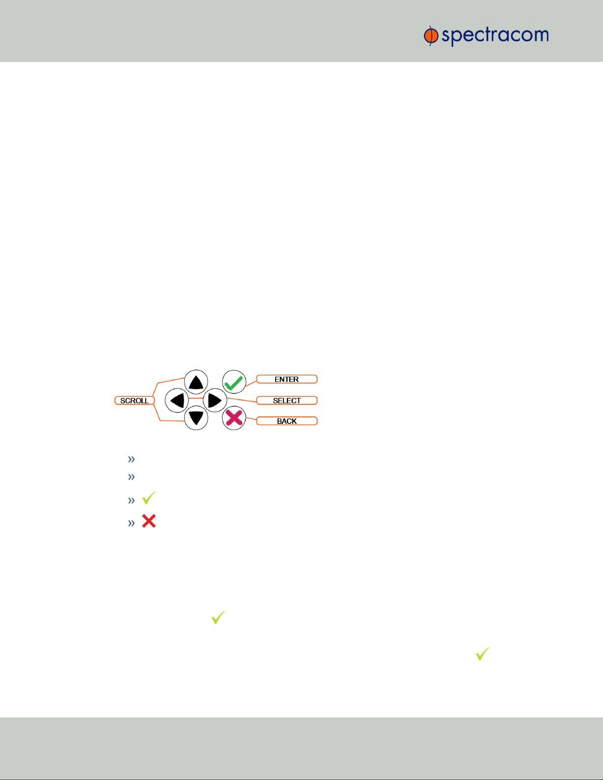
2.11 Setting up an IP Address
Turn on the unit with NO cable plugged into the Ethernet port yet (Note: once you apply
power, it may take up to two minutes for the system to fully boot).
Configure your PC‘s network interface card (NIC) with an IP address on the same network as
the NetClock 9489‘s default IP address ( 10.10.201.1 ). For example, configure the IP
address of your PC‘s network interface card as 10.10.201.10, with a subnet mask of
255.255.255.0.
Connect an Ethernet cable from your PC to the Ethernet port of the NetClock unit. Once connected via crossover cable, open a web browser and enter the NetClock‘s default IP address
(10.10.201.1) into the browser‘s address bar and login to the NetClock‘s WebUI as an
administrator. Once logged in, network settings for the NetClock can be configured under
MANAGEMENT > Network Setup > Actions: General Settings and under Ports: GEAR button.
2.11.2.2 Setting Up an IP Address via the Front Panel
Assigning an IP address to SecureSync, using the front panel keypad and information display
is a preferred way to provide network access to the unit, thus enabling you thereafter to complete the setup process via the WebUI.
Keypad Operation
The functions of the six keys are:
< > arrow keys: Navigate to a menu option (will be highlighted)
˄ ˅ arrow keys: Scroll through parameter values in edit displays
ENTER key: Select a menu option, or load a parameter when editing
BACK key: Return to previous display or abort an edit process
An illustration showing how to navigate the front panel menu tree can be found here: "Front
Panel Keypad, and Display" on page4
IP configuration, step-by-step instructions:
A.
Disable DHCP:
1.
Press the key.
2.
Using the arrow key, select Netv4 from the menu.
48
(To select a menu item, highlight it using the arrow keys, then press the key.)
CHAPTER 2 • SecureSync User Reference Guide Rev. 26
Page 65

3.
Select the Ethernet interface for which DHCP is to be disabled, such as eth0.
4.
Select DHCP from the next menu. The display will show State=Enabled and
Action=Disabled.
(The State is the current DHCP setting and the Action is the action to take. You can
only change the Action setting.)
5.
Press the key once to select the action, then again to apply it.
B.
Enter IP Address and Subnet Mask:
1.
Still on the Home > Netv4 > eth[0-3] menu, select IP Address, and
change "N=010.010.201.001/16” to the value of the static IP address and
subnet mask/network bits to be assigned (for a list of subnet mask values refer to
the table "Subnet mask values" on page53).
2.
Press the key once to enter the setting, then again to apply the new setting.
C.
Enter the Gateway Address (if required)
1.
Still on the Home > Netv4 menu, select the Gateway option (Home >
Netv4 > eth0 > Gateway).
2.11 Setting up an IP Address
2.
Press the key once to enter the setting, then again to apply the new setting.
3.
The display will change, allowing you to input an address at
N=000.000.000.001. Enter the gateway address here. The address entered must
correspond to the same network IP address assigned to SecureSync.
D.
Enable/disable the Port (if required)
1.
Still on the Home > Netv4 menu, select the eth[X]port that you want to
enable or disable.
Note: By default, eth0 is enabled, while all other ports are dis-
abled.
2.
Navigate to the Port option (Home > Netv4 > eth0 > Port).
3.
Press the ˄ ˅ arrow keys once to change between Enable and Disable.
After all applicable settings have been updated, press the key three times to return to the
main display. It should now resemble the following example:
CHAPTER 2 • SecureSync User Reference Guide Rev. 26
49
Page 66

2.11 Setting up an IP Address
Note: Despite having entered an IP address, the information display will show
0.0.0.0 if SecureSync could not detect an active link on the corresponding network interface.
Note: About DNS: The Primary and Secondary DNS servers are set automatically
if using DHCP. If DHCP is not available, they can be configured manually in the
SecureSync WebUI via the Network/General Setup screen.
The remainder of the configuration settings will be performed via the Web UI (accessed via an
external workstation with a web browser such as Firefox®or Chrome®). For more information,
see "The Web UI HOME Screen" on page18.
2.11.2.3 Setting Up a Static IP Address via a DHCP Network
To setup a permanent static IP address, after connecting SecureSync to a DHCP network:
1.
Enter the IP address shown on the front panel information display of your SecureSync
unit into the address field of your browser (on a computer connected to the SecureSync
network). If the network supports DNS, the hostname may also be entered instead (the
default hostname is "Spectracom"). The start screen of the SecureSync Web UI will be
displayed.
2.
Log into the Web UI as an administrator. The factory-default user name and password
are:
Username: spadmin
Password: admin123
3.
Disable DHCP by navigating to MANAGEMENT > Network Setup. In the Ports panel on
the right, click the GEAR icon next to the Ethernet Port you are using. In the Edit Ethernet
Port Settings window, uncheck the Enable DHCPv4 field. Do NOT click Submit or Apply
yet.
4.
In the fields below the Enable DHCPv4 checkbox, enter the desired Static IP address, Netmask, and Gateway address (if required). Click Submit.
50
For more information on network configuration, see: "Network Ports" on page57.
CHAPTER 2 • SecureSync User Reference Guide Rev. 26
Page 67

For subnet mask values, see "Subnet Mask Values" on page53.
5.
Verify on the front panel information display that the settings have been accepted by
SecureSync.
6.
Enter the static IP address into the address field of the browser, and again log into the
WebUI in order to continue with the configuration; see: "The Web UI HOME Screen"
on page18.
2.11.2.4 Setting Up an IP Address via the Serial Port
SecureSync's front panel serial port connector is a standard DB9 female connector. Communication with the serial port can be performed using a PC with a terminal emulator program
(such as PuTTY or TeraTerm) using a pinned straight-thru standard DB9M to DB9F serial cable.
The serial port can be used to make configuration changes (such as the network settings),
retrieve operational data (e.g., GNSS receiver information) and log files, or to perform operations such as resetting the admin password.
The serial port is account and password protected. You can login via the serial port using the
same user names and passwords as would be used to log into the SecureSync WebUI. Users
with “administrative rights” can perform all available commands. Users with “user” permissions
only can perform “get” commands that retrieve data, but cannot perform any “set” commands
or change/reset any passwords.
To configure an IP address via the serial port:
2.11 Setting up an IP Address
1.
Connect a serial cable to a PC running PuTTY, Tera Term, or HyperTerminal, and to
your SecureSync. For detailed information on the serial port connection, see "Setting up
a Terminal Emulator" on page512
2.
Login to SecureSync with a user account that has “admin” group rights, such as the
default spadmin account (the default password is admin123).
3.
Disable DHCP, type: dhcp4set 0 off <Enter>.
Note: If your SecureSync is configured with an Ethernet option card, use 0,
1, 2, 3 for eth0 – eth3.
Note: For a list of CLI commands, type helpcli, or see "CLICommands"
on page513.
4.
Configure the IP address and subnet mask, type:
ip4set 0 x.x.x.x y.y.y.y <Enter>
(where 0 is the desired interface, “x.x.x.x” is the desired IP address for
CHAPTER 2 • SecureSync User Reference Guide Rev. 26
51
Page 68

2.11 Setting up an IP Address
5.
Configure the gateway by typing gw4set 0 z.z.z.z<Enter>
(where 0 indicates which interface routing table to add the default gateway for, and
“z.z.z.z” is the default gateway address).
6.
Remove the serial cable, connect SecureSync to the network, and access the Web UI,
using the newly configured IP address. (For assistance, see "Accessing the WebUI" on
the facing page)
The remainder of the configuration settings will be performed via the Web UI (accessed via an
external workstation with a web browser such as Firefox®or Chrome®).
SecureSync, and “y.y.y.y” is the full subnet mask for the network (For a list of
subnet mask values, see "Subnet Mask Values" on the facing page.)
Note: If your SecureSync is configured with an Ethernet option card, use 0,
1, 2, 3 for eth0 – eth3.
2.11.2.5 Setting up a Static IP Address via Ethernet Cable
This procedure will allow you to configure SecureSync using the WebUI directly via the Ethernet port, if for some reason you prefer not to (or cannot) use a DHCP network.
1.
First, disable DHCP using the front panel keypad and information display:
a.
Press the ü key.
b.
Using the arrow key, select Netv4 from the menu.
(To select a menu item, highlight it using the arrow keys, then press the ü key.)
c.
Select the Ethernet interface for which DHCP is to be disabled, such as eth0.
d.
Select DHCP from the next menu. The display will show State=Enabled and
Action=Disabled.
(The State is the current DHCP setting and the Action is the action to take. You can
only change the Action setting.)
e.
Press the ü key once to select the action, then again to apply it.
2.
The front panel will now display the default static IP address 10.10.201.1/16.
3.
Change the workstation IP address to be on the same network as SecureSync.
4.
Connect workstation and SecureSync with an Ethernet cable.
Note: You may use an Ethernet crossover cable, but you do not have to.
52
The remainder of the configuration settings will be performed via the Web UI (accessed via an
external workstation with a web browser such as Firefox®or Chrome®). For more information,
see "The Web UI HOME Screen" on page18.
CHAPTER 2 • SecureSync User Reference Guide Rev. 26
Page 69

2.11.3 Subnet Mask Values
Network Bits Equivalent Netmask Network Bits Equivalent Netmask
30 255.255.255.252 18 255.255.192.0
29 255.255.255.248 17 255.255.128.0
28 255.255.255.240 16 255.255.0.0
27 255.255.255.224 15 255.254.0.0
26 255.255.255.192 14 255.252.0.0
25 255.255.255.128 13 255.248.0.0
24 255.255.255.0 12 255.240.0.0
23 255.255.254.0 11 255.224.0.0
22 255.255.252.0 10 255.192.0.0
21 255.255.248.0 9 255.128.0.0
20 255.255.240.0 8 255.0.0.0
19 255.255.224.0
2.12 Accessing the WebUI
Table 2-2:
Subnet mask values
2.12 Accessing the WebUI
SecureSync's web user interface ("WebUI") is the recommended means to interact with the
unit, since it provides access to nearly all configurable settings, and to obtain comprehensive
status information without having to use the Command Line Interpreter (CLI).
You can access the Web UI either by using the automatically assigned DHCP IP address, or by
using a manually set static IP address (see "Assigning a Static IP Address" on page45):
1.
On a computer connected to the SecureSync network, start a web browser, and enter the
IPaddress shown on the SecureSync front panel.
2.
When first connecting to the Web UI, a warning about security certificates may be displayed:
CHAPTER 2 • SecureSync User Reference Guide Rev. 26
53
Page 70

2.12 Accessing the WebUI
Select Continue....
Note: "Cookies" must be enabled. You will be notified if Cookies are dis-
abled in your browser.
Note: HTTPS only: Depending on your browser, the certificate/security
pop-up window may continue to be displayed each time you open the
Web UI until you saved the certificate in your browser.
Note: Static IPaddress only: To prevent the security pop-up window from
opening each time, a new SSL Certificate needs to be created using the
assigned IP address of SecureSync during the certificate generation. See
"HTTPS" on page65 for more information on creating a new SSL cer-
tificate.
3.
Log into the Web UI as an administrator. The factory-default administrator user name
and password are:
Username: spadmin
Password: admin123
Caution: For security reasons, it is advisable to change the default cre-
dentials, see: "Managing Passwords" on page251.
4.
Upon initial login, you will be asked to register your product. Spectracom recommends
to register SecureSync, so as to receive software updates and services notices. See also
"Product Registration" on page275.
Number of login attempts
The number of failed login attempts for ssh is hard-set to (4) four. This value is not configurable.
The number of failed login attempts for the Web UI (HTTP/HTTPS) is hard-set to (5) five failed
login attempts, with a 60 second lock. These two values are not configurable.
To continue with the configuration, see e.g., "The Web UI HOME Screen" on page18.
To learn more about setting up different types of user accounts, see "Managing User Accounts"
on page247.
54
CHAPTER 2 • SecureSync User Reference Guide Rev. 26
Page 71

2.13 Configuring Network Settings
Before configuring the network settings, you need to setup access to SecureSync web user interface ("Web UI"). This can be done by assigning a static IP address, or using a DHCP address.
For more information, see "Setting up an IP Address" on page44.
Once you have assigned the IP address, login to the Web UI. For more information, see
"Accessing the WebUI" on page53.
To configure network settings, or monitor your network, navigate to SecureSync's Network
Setup screen.
To access the Network Setup screen:
Navigate to MANAGEMENT > Network Setup. The Network Setup screen is divided into
three panels:
2.13 Configuring Network Settings
The Actions panel provides:
General Settings: Allows quick access to the primary network settings necessary to
connect SecureSync to a network. See "General Network Settings" on the next
page.
Web Interface Settings:
Web interface timeout: Determines how long a user can stay logged on.
For more information, see "Web UI Timeout" on page268.
Access Control: Allows the configuration of access restrictions from assigned net-
works/nodes.
Login Banner: Allows the administrator to configure a custom banner message to
be displayed on the SecureSync Web UI login page and the CLI (Note: There is a
2000 character size limit).
CHAPTER 2 • SecureSync User Reference Guide Rev. 26
55
Page 72

2.13 Configuring Network Settings
SSH : This button takes you to the SSH Setup window. For details on setting up
SSH, see "SSH" on page76.
HTTPS: This button takes you to the HTTPS Setup window. For details on setting up
HTTPS, see "HTTPS" on page65.
System Time Message: Setup a once-per-second time message to be sent to receiv-
ers via multicast. For details, see "System Time Message" on page93.
The Network Services panel is used to enable (ON) and disable (OFF) network services,
as well as the Web UI display mode, details see: "Network Services" on page60.
The Ports panel not only displays STATUS information, but is used also to set up and man-
age SecureSync’s network ports via three buttons:
INFObutton: Displays the Ethernet port Status window for review purposes.
GEAR button: Displays the Ethernet port settings window for editing purposes.
TABLE button: Displays a window that allows adding, editing, and reviewing
Static Routes.
2.13.1 General Network Settings
To expedite network setup, SecureSync provides the General Settings window, allowing quick
access to the primary network settings.
To access the General Settings window:
1.
Navigate to MANAGEMENT > Network Setup. In the Actions Panel on the left, click Gen-
eral Settings.
56
CHAPTER 2 • SecureSync User Reference Guide Rev. 26
Page 73

2.
Populate the fields:
Hostname: This is the server’s identity on the network or IP address. The default is
Spectracom
Default Gateway IPv6: The gateway (default router) address is needed if com-
munication to the SecureSync is made outside of the local network. By default, the
gateway is disabled in the format “####:####” where each ‘#’ is a hexa-
decimal value. When a DHCP server is not requested or is requested but not available and DHCP IPv6 is enabled, the server will use this Default Gateway.
2.13 Configuring Network Settings
.
Default Port: Unless you specify a specific Port to be used as Default Port, the fact-
ory default port eth0 will be used as the gateway (default gateway).
The General Settings window also displays the IPv4 Address and default IPv4 Gateway.
2.13.2 Network Ports
Ports act as communication endpoints in a network. The hardware configuration of your unit
will determine which ports (e.g., Eth0, Eth1, ...) are available for use. Before using a port, it
needs to be enabled and configured.
To enable & configure, or view a network port:
1.
Navigate to MANAGEMENT > NETWORK: Network Setup.
2.
The Ports panel on the right side of the screen lists the available Ethernet ports, and their
connection status:
Green: CONNECTED (showing the connection speed)
Yellow: CABLE UNPLUGGED (the port is enabled but there is no cable attached)
Red: DISABLED.
Locate the port you want to configure and click the GEAR button to enable & configure the port, or the INFO button to view the port status.
CHAPTER 2 • SecureSync User Reference Guide Rev. 26
57
Page 74

2.13 Configuring Network Settings
Note: The eth0 port is the built-in SecureSync Ethernet port (i.e.,
standard, not optional).
3.
If the port is not already enabled, in the Edit Ethernet Ports Settings window, click the
Enable check box. The Edit Ethernet Ports Settings window will expand to show the options
needed to complete the port setup.
Fill in the fields as required:
Domain: This is the domain name to be associated with this port.
Enable DHCPv4: Check this box to enable the delivery of IP addresses
from a DHCP Server using the DHCPv4 protocol. This box is checked by
default. Should you disable (uncheck) DHCPv4, the following fields will display and must be completed:
58
CHAPTER 2 • SecureSync User Reference Guide Rev. 26
Page 75
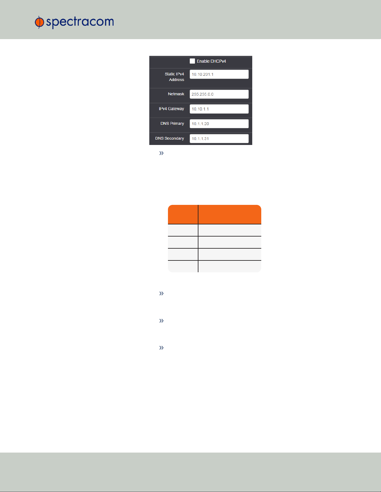
ETH port
Default "static lease"
IP address
ETH0 10.10.201.1
ETH1 10.10.201.2
ETH2 10.10.201.3
ETH3 10.10.201.4
2.13 Configuring Network Settings
Static IPv4 Address: This is the unique address assigned by the net-
work administrator. The default static IP address of the SecureSync
unit is 10.10.201.1. In the format “#.#.#.#” with no leading zeroes or spaces, where each ‘#’ is a decimal integer from the range
[0,255].
Table 2-3:
Default IP addresses
The default subnet is: 255.255.0.0
Netmask: This is the network subnet mask assigned by the network
administrator. In the form “xxx.xxx.xxx.xxx.” See "Subnet
Mask Values" on page53 for a list of subnet mask values.
IPv4 Gateway: The gateway (default router) address is needed if
communication to the SecureSync is made outside of the local network. By default, the gateway is disabled.
DNS Primary: This is the primary DNS address to be used for this
port.
Depending on how your DHCP server is configured, this is set automatically once DHCP is enabled. Alternatively, you may configure
your DHCP server to NOT use a DNS address. When DHCP is dis-
abled, DNS Primary is set manually, using the format "#.#.#.#"
CHAPTER 2 • SecureSync User Reference Guide Rev. 26
59
Page 76

2.13 Configuring Network Settings
with no leading zeroes or spaces, where each ‘#’ is a decimal
integer from the range [0,255].
DNS Secondary: This is the secondary DNS address to be used for
this port. Depending on how your DHCP server is configured, this is
set automatically once DHCP is enabled, or your DHCP server may
be configured NOT to set a DNS address.
When DHCP is disabled, DNS Secondary is set manually, using the
format “#.#.#.#” with no leading zeroes or spaces, where each
‘#’ is a decimal integer from the range [0,255].
Enable DHCPv6: Check this box to enable the delivery of IPv6 addresses
from a DHCP Server using the DHCPv6 protocol.
IPv6 addresses can be added and deleted by clicking the Edit IPv6
Address button at the bottom of the screen:
4.
To apply your changes, click Submit (the window will close), or Apply.
2.13.3 Network Services
Several standard network services can be enabled or disabled via the easily accessible Net-
work Services Panel under MANAGEMENT > Network Setup:
60
Note: If the button is not displayed, you need to
Enable this port first, and click Submit.
Enable SLAAC: Check this box to enable stateless address auto con-
figuration.
MTU: Maximum Transmission Unit. Range (for Ethernetv2): Default: 1500
bytes. Smaller packages are recommended, if encapsulation is required
e.g., to meet encryption needs, which would cause the maximum package
size to be exceeded.
CHAPTER 2 • SecureSync User Reference Guide Rev. 26
Page 77
2.13 Configuring Network Settings
The Network Services panel has ON/OFF toggle switches for the following daemons and fea-
tures:
System Time Message: A once-per second Time Message sent out via Multicast; for
details, see "System Time Message" on page93.
Daytime Protocol, RFC-867: A standard Internet service, featuring an ASCII daytime rep-
resentation, often used for diagnostic purposes.
Time Protocol, RFC-868: This protocol is used to provide a machine-readable, site-inde-
pendent date and time.
Telnet: Remote configuration
FTP server: Access to logs
SSH: Secure Shell cryptographic network protocol for secure data communication
HTTP: Hypertext Transfer Protocol
HTTPS: Hypertext Transfer Protocol Secure
Classic UI: This toggle switch allows the SecureSync Classic User Interface (as used in
SecureSync Web UI Version 5.0.2 and older) to be turned ON or OFF [Default = OFF].
To enable, select the ON position, and refresh the browser window (the refresh may
take a moment). Then click the CLASSIC INTERFACE button that will appear in the top
right hand corner to switch to the Classic UI. The Classic UI is accessed via the non-standard port 8080 (e.g., https://10.10.122.32:8080).
Note that 3rd party security scan tools may report a security issue if the Classic UI is
ON.
To enable/disable the Classic UI via the CLI (e.g., when using an older browser that
does not support the current UI, use the commands servget and servset.
CHAPTER 2 • SecureSync User Reference Guide Rev. 26
61
Page 78

2.13 Configuring Network Settings
tcpdump: A LINUX program that can be used to monitor network traffic by inspecting tcp
packets. Default = ON.
If not needed, or wanted (out of concern for potential security risks), tcpdump can be disabled permanently: Once toggled to OFF, and after executing a page reload, tcpdump
will be deleted from the system: The toggle switch will be removed, and the function cannot be enabled again (even after a software upgrade).
iptables
While not accessible via the WebUI, iptables (an application allowing for customizable access
restrictions) have been supported since SecureSync Software Version 5.4.1.
Note that iptables is always ON, and its policies can only be accessed via the Command Line
Interface (see "CLICommands" on page513) in combination with the Sudo command. Please
also note that you need to have admin user rights to run this command.
Note: A listing of recommended and default network settings can be found under
"Default and Recommended Configurations" on page328.
2.13.4 Static Routes
Static routes are manually configured routes used by network data traffic, rather than solely
relying on routes chosen automatically by DHCP (Dynamic Host Configuration Protocol). With
statically configured networks, static routes are in fact the only possible way to route network
traffic.
To view, add, edit, or delete a static route:
1.
Navigate to the MANAGEMENT > Network Setup screen.
2.
The Ports panel displays the available Ethernet ports, and their connection status:
62
CHAPTER 2 • SecureSync User Reference Guide Rev. 26
Page 79
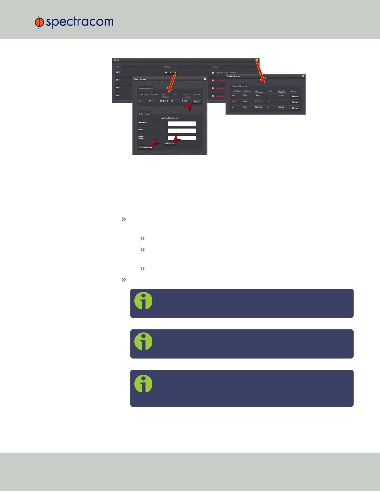
2.13 Configuring Network Settings
3.
To view all configured Static Routes for all Ethernet Ports, or delete one or more Static
Routes, click the TABLE icon in the top-right corner.
4.
To add a new Route, view or delete an existing Route for a specific Ethernet Port, locate
the Port listing you want to configure, and click the TABLE button next to it.
The Static Routes window for the chosen Port will open, displaying its Routing Table, and
an Add Route panel.
In the Add Route panel, populate these fields in order to assign a Static Route to a
Port:
Net Address: This is the address/subnet to route to.
Prefix: This is the subnet mask in prefix form e.g., "24". See also "Subnet
Mask Values" on page53.
RouterAddress: This is where you will go through to get there.
Click the Add Route button at the bottom of the screen.
Note: To set up a static route, the Ethernet connector must be phys-
ically connected to the network.
Note: Do not use the same route for different Ethernet ports; a route
that has been used elsewhere will be rejected.
Note: The eth0 port is the default port for static routing. If a port is
not given its own static route, all packets from that port will be sent
through the default.
CHAPTER 2 • SecureSync User Reference Guide Rev. 26
63
Page 80

2.13 Configuring Network Settings
2.13.5 Access Rules
Network access rules restrict access to only those assigned networks or nodes defined. If no
access rules are defined, access will be granted to all networks and nodes.
Note: In order to configure Access Rules, you need ADMINISTRATORrights.
To configure a new, or delete an existing access rule:
1.
Navigate to the MANAGEMENT > Network Setup screen.
2.
In the Actions panel on the left, click on Access Control.
3.
The Network Access Rules window displays:
4.
In the Allow From field, enter a valid IP address. It is not possible, however, to add direct
IP addresses, but instead they must be input as blocks, i.e. you need to add /32 at the
end of an IP address to ensure that only that address is allowed.
Example: 10.2.100.29/32 will allow only 10.2.100.29 access.
I P a d d r e s s n o m e n c l a t u r e :
IPv4—10.10.0.0/16, where 10.10.0.0 is the IP address and 16 is the subnet
mask in prefix form. See the table "Subnet Mask Values" on page53 for a list of subnet
mask values.
IPv6—2001:db8::/48, representing 2001:db8:0:0:0:0:0:0 to 2001:d-
b8:0:ffff:ffff:ffff:ffff:ffff.
5.
Click the Add button in the Action column to add the new rule.
6.
The established rule appears in the Network Access Rules window.
64
CHAPTER 2 • SecureSync User Reference Guide Rev. 26
Page 81
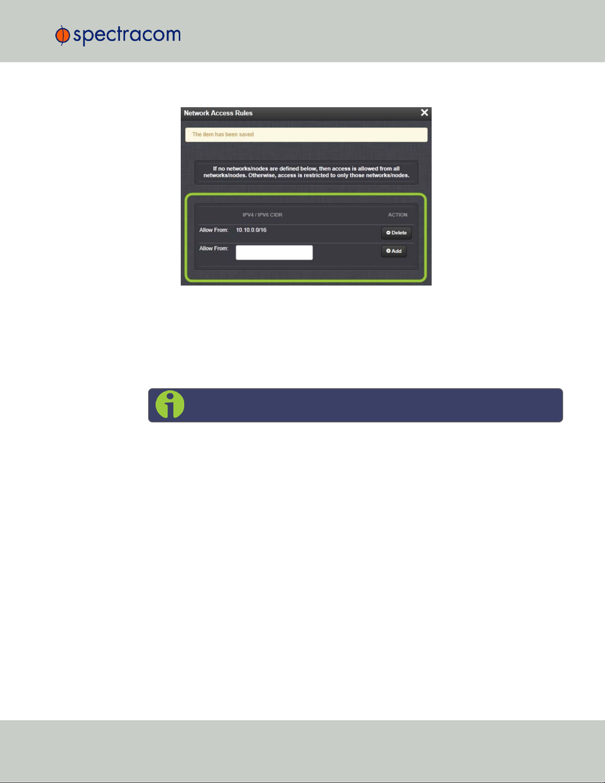
2.13.6 HTTPS
2.13 Configuring Network Settings
Click the Delete button next to an existing rule, if you want to delete it.
HTTPS stands for HyperText Transfer Protocol over SSL (Secure Socket Layer). This TCP/IP protocol is used to transfer and display data securely by adding an encryption layer to protect the
integrity and privacy of data traffic. Certificates issued by trusted authorities are used for
sender/recipient authentication.
Note: In order to configure HTTPS, you need ADMINISTRATORrights.
Note that SecureSync supports two different modes of HTTPS operation: The Standard HTTPS
Level (default), and a High-Security Level. For more information, see "HTTPS Security Levels" on
page266.
2.13.6.1 Accessing the HTTPS Setup Window
1.
Navigate to MANAGEMENT > NETWORK: HTTPS Setup (or, navigate to MANAGEMENT >
Network Setup, and click HTTPS in the Actions panel on the left):
CHAPTER 2 • SecureSync User Reference Guide Rev. 26
65
Page 82

2.13 Configuring Network Settings
The HTTPS Setup window has five tabs:
Create Certificate Request: This menu utilizes the OpenSSL library to generate cer-
tificate Requests and self-signed certificates.
Subject Alternative Name Extension: This menu is used to add alternative names to an
X.509 extension of a Certificate Request.
Certificate Request: A holder for the certificate request generated under the Create
Certificate Request tab. Copy and paste this Certificate text in order to send it to
your Certificate Authority.
Upload X.509 PEM Certificate: Use the window under this tab to paste your X.509
certificate text and upload it to SecureSync.
Upload Certificate File: Use this tab to upload your certificate file returned by the Cer-
tificate Authority. For more information on format types, see "Supported Certificate
Formats" on the facing page.
Exit the HTTPS Setup window by clicking the X icon in the top right window corner, or by clicking anywhere outside the window.
Should you exit the HTTPS Setup window while filling out the certificate request parameters
form
before
HTTPS Setup window will not lose and Subject Alternative Names that have been entered.
When switching between tabs within the HTTPS Setup window, the information you have
entered will be retained.
clicking the Submit button, any information you entered will be lost. Exiting the
66
CHAPTER 2 • SecureSync User Reference Guide Rev. 26
Page 83

2.13.6.2 About HTTPS
HTTPS provides secure/encrypted, web-based management and configuration of SecureSync
from a PC. In order to establish a secure HTTPS connection, an SSL certificate must be stored
inside the SecureSync unit.
SecureSync uses the OpenSSL library to create certificate requests and self-signed certificates.
The OpenSSL library provides the encryption algorithms used for secure HTTP (HTTPS). The
OpenSSL package also provides tools and software for creating X.509 Certificate Requests,
Self Signed Certificates and Private/Public Keys. For more information on OpenSSL, please
see www.openssl.org.
Once you created a certificate request, submit the request to an external Certificate Authority
(CA) for the creation of a third party verifiable certificate. (It is also possible to use an internal
corporate Certificate Authority.)
If a Certificate Authority is not available, or while you are waiting for the certificate to be
issued, you can use the default Spectracom self-signed SSL certificate that comes with the unit
until it expires, or use your own self-signed certificate. The typical life span of a certificate (i.e.,
during which HTTPS is available for use) is about 10years.
2.13 Configuring Network Settings
Note: If deleted, the HTTPS certificate cannot be restored. A new certificate will
need to be generated.
Note: In a Chrome web browser, if a valid certificate is deleted or changed such
that it becomes invalid, it is necessary to navigate to Chrome's Settings> More
Tools> Clear browsing data> Advanced and clear the Cached images and files in
the history. Otherwise Chrome's security warnings may make some data unavailable in the Web UI.
Note: If the IP Address or Common Name (Host Name) is changed, you need to
regenerate the certificate, or you will receive security warnings from your web
browser each time you log in.
2.13.6.3 Supported Certificate Formats
SecureSync supports X.509 PEM and DER Certificates, as well as PKCS#7 PEM and DER formatted Certificates.
You can create a unique X.509 self-signed Certificate, an RSA private key and X.509 certificate request using the WebUI. RSA private keys are supported because they are the most
widely accepted. At this time, DSA keys are not supported.
CHAPTER 2 • SecureSync User Reference Guide Rev. 26
67
Page 84

2.13 Configuring Network Settings
SecureSync supports two different modes of HTTPS operation: The Standard HTTPS Level
(default), and a High- Security Level. For more information, see "HTTPS Security Levels" on
page266.
2.13.6.4 Creating an HTTPS Certificate Request
Caution: If you plan on entering multiple Subject Alternative Names to your HTTPS
Certificate Request, you must do so before filling out the Create Certificate
Request tab to avoid losing any information. See "Adding HTTPS Subject Altern-
ative Names" on page71.
To create an HTTPS Certificate Request:
1.
Navigate to MANAGEMENT > NETWORK:HTTPS Setup, or in the MANAGEMENT >
NETWORK Setup, Actions panel, select HTTPS:
2.
Click the Create Certificate Request tab (this is the default tab).
3.
Check the box Create Self Signed Certificate, in order to open up all menu items.
This checkbox serves as a security feature: Check the box only if you are certain about
generating a new self-signed Certificate.
Caution: Once you click Submit, a previously generated Certificate (or the
Spectracom default Certificate) will be overwritten.
Note that an invalid Certificate may result in denial of access to SecureSync via the
Web UI! (If this occurs, see "If a Secure Unit Becomes Inaccessible" on page268.)
4.
Fill in the available fields:
Signature Algorithm: Choose the algorithm to be used from:
MD4
SHA1
68
CHAPTER 2 • SecureSync User Reference Guide Rev. 26
Page 85

2.13 Configuring Network Settings
SHA256
SHA512
Private Key Pass Phrase: This is the RSA decryption key. This must be at least
4characters long.
RSA Private Key Bit Length: 2048 bits is the default. Using a lower number may
compromise security and is not recommended.
Two-Letter Country Code: This code should match the ISO-3166-1 value for the
country in question.
State Or Province Name: From the address of the organization creating up the Cer-
tificate.
Locality Name: Locale of the organization creating the Certificate.
Organization Name: The name of the organization creating the Certificate.
Organization Unit Name: The applicable subdivision of the organization creating
the Certificate.
Common Name (e.g. Hostname or IP): This is the name of the host being authen-
ticated. The Common Name field in the X.509 Certificate must match the hostname, IP address, or URL used to reach the host via HTTPS.
Email Address: This is the email address of the organization creating the Cer-
tificate.
Challenge Password: Valid response password to server challenge.
Optional Organization Name: An optional name for the organization creating the
Certificate.
Self-Signed Certificate Expiration (Days): How many days before the Certificate
expires. The default is 7200.
5.
Fill in the available fields:
Signature Algorithm: Choose the algorithm to be used from:
MD4
SHA1
SHA256
SHA512
Private Key Pass Phrase: This is the RSA decryption key. This must be at least
4characters long.
RSA Private Key Bit Length: 2048 bits is the default. Using a lower number may
compromise security and is not recommended.
Two-Letter Country Code: This code should match the ISO-3166-1 value for the
country in question.
CHAPTER 2 • SecureSync User Reference Guide Rev. 26
69
Page 86

2.13 Configuring Network Settings
State Or Province Name: From the address of the organization creating up the Cer-
tificate.
Locality Name: Locale of the organization creating the Certificate.
Organization Name: The name of the organization creating the Certificate.
Organization Unit Name: The applicable subdivision of the organization creating
the Certificate.
Common Name (e.g. Hostname or IP): This is the name of the host being authen-
ticated. The Common Name field in the X.509 Certificate must match the hostname, IP address, or URL used to reach the host via HTTPS.
Email Address: This is the email address of the organization creating the Cer-
tificate.
Challenge Password: Valid response password to server challenge.
Optional Organization Name: An optional name for the organization creating the
Certificate.
Self-Signed Certificate Expiration (Days): How many days before the Certificate
expires. The default is 7200.
You are required to select a signature algorithm, a private key passphrase of at least
4characters, a private key bit length, and the Certificate expiration in days. The remaining fields are optional.
It is recommended that you consult your Certificate Authority for the required fields in an
X509-Certificate request. Spectracom recommends all fields be filled out and match the
information given to your Certificate Authority. For example, use all abbreviations,
spellings, URLs, and company departments recognized by the Certificate Authority. This
helps to avoid problems the Certificate Authority might otherwise have reconciling Certificate request and company record information.
If necessary, consult your web browser vendor’s documentation and Certificate Authority
to see which key bit lengths and signature algorithms your web browser supports.
Spectracom recommends that when completing the Common Name field, the user
provide a static IP address, because DHCP-generated IP addresses can change. If the
hostname or IP address changes, the X.509 Certificate must be regenerated.
It is recommended that the RSA Private Key Bit Length be a power of 2 or multiple of 2.
The key bit length chosen is typically 1024, but can range from 512 to 4096. Long key
bit lengths of up to 4096 are not recommended because they can take several hours to
generate. The most common key bit length is the value 1024.
Note: The default key bit length value is 2048.
70
When using a self-signed Certificate, choose values based on your company’s security
policy.
CHAPTER 2 • SecureSync User Reference Guide Rev. 26
Page 87

2.13 Configuring Network Settings
6.
When the form is complete, confirm that you checked the box Create Self Signed Cer-
tificate at the top of the window, then click Submit. Clicking the Submit button auto-
matically generates the Certificate Request in the proper format for subsequent
submission to the Certificate Authority.
Note: It may take several minutes for SecureSync to create the Certificate
request and the private key (larger keys will require more time than small
keys). If the unit is rebooted during this time, the Certificate will not be created.
To view the newly generated request, in the HTTPS Setup window, click the Certificate
Request tab.
When switching between tabs within the HTTPS Setup window, the information you have
entered will be retained. If you exit the HTTPS Setup window before clicking Submit, the
information will be lost.
2.13.6.5 Adding HTTPS Subject Alternative Names
Caution: Subject Alternative Names must be added before a new Certificate
Request is generated, otherwise the Certificate Request will have to be created
again to include the Subject Alternative Names. Any information entered into the
Create Certificate Request tab that has not been submitted will be lost by adding,
deleting, or editing Subject Alternative Names.
CHAPTER 2 • SecureSync User Reference Guide Rev. 26
71
Page 88

2.13 Configuring Network Settings
It is recommended that you consult your Certificate Authority regarding questions of Subject
Alternative Name usage.
To add Subject Alternative Names to an HTTPS Certificate Request:
1.
Navigate to MANAGEMENT > NETWORK:HTTPS Setup (or, navigate to MANAGEMENT
> NETWORK Setup, and click HTTPS in the Actions panel.
2.
In the Subject Alternative Name Extension tab, select the plus icon to access the Add Subject Alternative Name popup.
3.
Fill in the available fields:
Type [DNS, IP, email, URI, RID, dirName]
Name
for Directory Subject Alternative Names (dirName), check the Directory Name
box, and additional optional fields will be available:
Two Letter Country Code: must match ISO-3166-1 value.
Organization name: name of orgainzation creating certificate.
Organizational Unit Name: The applicable subdivision of the organization creating the certificate.
Common name: The name of the host being authenticated. The Common
Name field in the X.509 Certificate must match the host name, IP address,
or URL used to reach the host via HTTPS.
4.
After completing and submitting the form, view the Subject Alternative Name tab to see
existing entries. Existing Subject Alternative Names can be edited or deleted from this
window.
72
CHAPTER 2 • SecureSync User Reference Guide Rev. 26
Page 89

5.
After adding all the desired Subject Alternative Names, follow instructions for "Creating
an HTTPS Certificate Request" on page68.
2.13.6.6 Requesting an HTTPS Certificate
Before requesting an HTTPS Certificate from a third-party Certificate Authority, you need to create a Certificate Request:
1.
Navigate to MANAGEMENT > HTTPS Setup, or to MANAGEMENT > Network Setup >
Actions panel: HTTPS.
2.
In the HTTPS Setup window, under the Certificate Request Parameters tab, complete the
form as described under "Creating an HTTPS Certificate Request" on page68.
3.
Click Submit to generate your Certificate Request.
4.
You have now created a Certificate Request. Navigate to the Certificate Request tab to
view it:
2.13 Configuring Network Settings
5.
Copy the generated Certificate Request from the Certificate Request window, and paste
and submit it per the guidelines of your Certificate Authority. The Certificate Authority
will issue a verifiable, authenticable third-party certificate.
6.
OPTIONAL: While waiting for the certificate to be issued by the Certificate Authority,
you may use the certificate from the Certificate Request window as a self-signed certificate (see below).
NOTE: Preventing accidental overwriting of an existing certificate:
If you plan on using a new Certificate Request, fill out a new form under the Certificate Request
Parameters tab. Be aware, though, that the newly generated Certificate Request will replace the
Certificate Request previously generated once you submit it. Therefore, if you wish to retain
your previously generated Certificate Request for any reason, copy its text, and paste it into a
separate text file. Save the file before generating a new request.
CHAPTER 2 • SecureSync User Reference Guide Rev. 26
73
Page 90

2.13 Configuring Network Settings
Using a Self-Signed Certificate
In the process of generating a Certificate Request, a self-signed certificate will automatically be
generated simultaneously. It will be displayed under the Certificate Request tab.
You may use your self-signed certificate (or the default Spectracom self-signed certificate that
comes with the unit) while waiting for the HTTPS certificate from the Certificate Authority, or – if
a Certificate Authority is not available – until it expires. The typical life span of a certificate is
about 10years.
NOTE: When accessing the SecureSync WebUI while using the self-signed certificate, your
Windows®web browser will ask you to confirm that you want to access this site via https with
only a self-signed certificate in place. Other operating systems may vary in how they install and
accept certificates. External Internet access may be required by your Certificate Authority to
verify your certificate.
2.13.6.7 Uploading an X.509 PEM Certificate Text
Many Certificate Authorities simply issue a Certificate in the form of a plain text file. If your
Certificate was provided in this manner, and the Certificate is in the X.509 PEM format, follow
the procedure below to upload the Certificate text by copying and pasting it into the WebUI.
Note: Only X.509 PEM Certificates can be loaded in this manner. Certificates
issued in other formats must be uploaded via the Upload Certificate tab.
Certificate Chain
It is also possible to upload a X.509 PEM Certificate Chain by pasting the text of the second
certificate behind the regular CA Certificate.
Uploading X.509 PEM certificate text
To upload an X.509 PEM Certificate text to SecureSync:
1.
Navigate to MANAGEMENT > NETWORK: HTTPS Setup.
2.
Select the Upload X.509 PEM Certificate tab.
74
CHAPTER 2 • SecureSync User Reference Guide Rev. 26
Page 91

2.13 Configuring Network Settings
3.
Copy the text of the Certificate that was issued to you by your Certificate Authority, and
paste it into the text field.
4.
Click Submit to upload the Certificate to SecureSync.
NOTE: The text inside the text field under the Edit X.509 PEM Certificate tab is editable.
However, changes should not be made to a Certificate once it is imported; instead, a new Certificate should be requested. An invalid Certificate may result in denial of access to the
SecureSync through the Web UI. If this occurs, see "If a Secure Unit Becomes Inaccessible" on
page268.
2.13.6.8 Uploading an HTTPS Certificate File
Once the HTTPS Certificate has been issued by your Certificate Authority, you have to upload
the Certificate file to SecureSync, unless it is a X.509 PEM-format Certificate: In this case you
may also upload the pasted Certificate text directly, see "Uploading an X.509 PEM Certificate
Text" on the previous page.
Note: For more information about Certificate formats, see "Supported Certificate
Formats" on page67.
To upload an HTTPS certificate file to SecureSync:
1.
Store the Public Keys File provided to you by the Certificate Authority in a location
accessible from the computer on which you are running the WebUI.
2.
In the WebUI, navigate to MANAGEMENT > NETWORK: HTTPS Setup.
3.
Select the tab Upload Certificate File.
CHAPTER 2 • SecureSync User Reference Guide Rev. 26
75
Page 92

2.13 Configuring Network Settings
4.
Choose the Certificate Type for the HTTPS Certificate supplied by the Certificate Authority from the Certification Type drop-down menu:
PEM
DER
PKCS #7 PEM
PKCS #7 DER
5.
6.
Certificate Chain
It is possible to upload a X.509PEM Certificate Chain file. Note that there should be no character between the Certificate texts.
2.13.7 SSH
The SSH, or Secure Shell, protocol is a cryptographic network protocol, allowing secure
remote login by establishing a secure channel between an SSH client and an SSH server. SSH
uses host keys to uniquely identify each SSH server. Host keys are used for server authentication
and identification. A secure unit permits users to create or delete RSA or DSA keys for the
SSH2 protocol.
Click the Browse… button and locate the Public Keys File provided by the Certificate
Authority in its location where you stored it in step 1.
Click Submit.
Note: SecureSync will automatically format the Certificate into the X.509
PEM format.
76
Note: Only SSH2 is supported due to vulnerabilities in the SSH1 protocol.
CHAPTER 2 • SecureSync User Reference Guide Rev. 26
Page 93

2.13 Configuring Network Settings
The SSH tools supported by SecureSync are:
SSH: Secure Shell
SCP: Secure Copy
SFTP: Secure File Transfer Protocol
SecureSync implements the server components of SSH, SCP, and SFTP.
For more information on OpenSSH, please refer to www.openssh.org.
To configure SSH:
1.
Navigate to MANAGEMENT > NETWORK: SSH Setup. The SSH Setup window will dis-
play.
The window contains two tabs:
Host Keys: SSH uses Host Keys to uniquely identify each SSH server. Host keys
are used for server authentication and identification.
Public Key: This is a text field interface that allows the user to edit the public key
files authorized_keys file.
Note: Should you exit the SSH Setup window (by clicking X in the top right
corner of the window, or by clicking anywhere outside of the window),
while filling out the Certificate Request Parameters form before clicking
Submit, any information you entered will be lost. When switching between
tabs within the SSH Setup window, however, the information you have
entered will be retained.
Host Keys
You may choose to delete individual RSA or DSA host keys. Should you decide to delete the
RSA or DSA key, the SSH will function, but that form of server authentication will not be available. Should you delete both the RSA and DSA keys, SSH will not function. In addition, if SSH
host keys are being generated at the time of deletion, the key generation processes are
stopped, any keys created will be deleted, and all key bit sizes are set to 0.
CHAPTER 2 • SecureSync User Reference Guide Rev. 26
77
Page 94

2.13 Configuring Network Settings
You may choose to delete existing keys and request the creation of new keys, but it is often simpler to make these requests separately.
You can create individual RSA and DSA Host Public/Private Key pairs. Host keys must first be
deleted before new Host Keys can be created.
SecureSync units have their initial host keys created at the factory. RSA host key sizes can vary
between 768 and 4096 bits. The recommended key size is 1024. Though many key sizes are
supported, it is recommended that users select key sizes that are powers of 2 or divisible by 2.
The most popular sizes are 768, 1024, and 2048. Large key sizes of up to 4096 are supported, but may take 10 minutes or more to generate. DSA keys size support is limited to 1024
bits.
Host keys are generated in the background. Creating RSA and DSA keys, each with 1024 bits
length, typically takes about 30 seconds. Keys are created in the order of RSA, DSA, RSA.
When the keys are created, you can successfully make SSH client connections. If the unit is
rebooted with host key creation in progress, or the unit is booted and no host keys exist, the
key generation process is restarted. The key generation process uses either the previously specified key sizes or, if a key size is undefined, the default key bit length size used is 2048. A key
with a zero length or blank key size field is not created.
The SSH client utilities SSH, SCP, and SFTP allow for several modes of user authentication.
SSH allows you to remotely login or transfer files by identifying your account and the target
machine's IP address. As a user you can authenticate yourself by using your account password,
or by using a Public Private Key Pair.
It is advisable to keep your private key secret within your workstation or network user account,
and provide the SecureSync a copy of your public key. The modes of authentication supported
include:
Either Public Key with Passphrase or Login Account Password
Login Account Password only
Public Key with Passphrase only
SSH using public/private key authentication is the most secure authenticating method for SSH,
SCP or SFTP sessions.
You are required to create private and public key pairs on your workstation or within a
private area in your network account. These keys may be RSA or DSA and may be any key bit
length as supported by the SSH client tool. These public keys are stored in a file in the .ssh
directory named authorized_keys. The file is to be formatted such that the key is followed
by the optional comment with only one key per line.
Note: The file format, line terminations, and other EOL or EOF characters should
correspond to UNIX conventions, not Windows.
Changing Key Length Values
You may change the key length of the RSA, DSA, ECDSA, and ED25519 type host keys.
78
CHAPTER 2 • SecureSync User Reference Guide Rev. 26
Page 95

To change the key length of a host key:
1.
Navigate to MANAGEMENT > NETWORK: SSH Setup. The SSH Setup window will open
to the Host Keys tab by default.
2.
Select the Key Length value for the key type you want to change.
Key sizes that are powers of 2 or divisible by 2 are recommended. The most popular
sizes are 768, 1024, and 2048. Large key sizes of up to 4096 are supported, but may
take 10 minutes or more to generate. DSA keys size support is limited to 1024 bits. The
key type ED25519 supports 256 bits.
2.13 Configuring Network Settings
3.
Check the Regenerate All Keys box.
4.
Click Submit. The new values will be saved.
Note: Changing the values and submitting them in this manner DOES NOT gen-
erate new host public/private key pairs. See "Creating Host Public/Private Key
Pairs" on the next page for information on how to create new host public/private
key pairs.
Deleting Host Keys
You can delete individual host keys. To delete a key:
1.
Navigate to MANAGEMENT > NETWORK: SSH Setup. The window will open to the Host
Keys tab by default.
CHAPTER 2 • SecureSync User Reference Guide Rev. 26
79
Page 96

2.13 Configuring Network Settings
2.
Select Delete in the field for the key you wish to delete, and click Submit.
Creating Host Public/Private Key Pairs
You may create individualHost Public/Private Key pairs. Host keys must first be deleted before
new Host Keys can be created. To create a new set of host keys:
1.
To access the SSH setup screen, navigate to MANAGEMENT > NETWORK: SSH Setup.
The window will open to the Host Keys tab by default.
2.
Should you want to change the key length of any host key, enter the desired length in the
text field corresponding to the length you wish to change.
3.
Check the Regenerate All Keys box.
4.
Click Submit.
The KeyType/Status/Action table will temporarily disappear while the SecureSync
regenerates the keys. The Host keys are generated in the background. Creating RSA and
DSA keys, each with 1024 bits length, typically takes about 30 seconds. Keys are created in the order of RSA, DSA, ECDSA, ED25519. SecureSync will generate all 4 host
keys, RSA, DSA, ECDSA, and ED25519.
5.
Delete any of the keys you do not want. See "Deleting Host Keys" on the previous page.
80
CHAPTER 2 • SecureSync User Reference Guide Rev. 26
Page 97

2.13 Configuring Network Settings
Note: If the unit is rebooted with host key creation in progress, or the unit is
booted and no host keys exist, the key generation process is restarted. The
key generation process uses the previously specified key sizes.
Note: If a key size is undefined, the default key bit length size used is
2048. A key with a zero length or blank key size field will not be created.
When you delete a host key and recreate a new one, SSH client sessions will warn you that the
host key has changed for this particular IP address. You must then take one of the following
actions:
1.
Override the warning and accept the new Public Host Key and start a new connection.
This is the default. This option allows users to login using either method. Whichever
mode works is allowed for logging in. If the Public Key is not correct or the Passphrase
is not valid the user is then prompted for the login account password.
2.
Remove the old Host Public Key from their client system and accept the new Host Public
Key. This option simply skips public/private key authentication and immediately prompts
the user for password over a secure encrypted session avoiding sending passwords in
the clear.
3.
Load a public key into SecureSync. This public key must match the private key found in
the users account and be accessible to the SSH, SCP, or SFTP client program. The user
must then enter the Passphrase after authentication of the keys to provide the second
factor for 2-factor authentication.
Please consult your specific SSH client’s software’s documentation.
Public Keys: Viewing, Editing, Loading
The authorized_keys file can be viewed and edited, so as to enable adding and deleting Public Keys. The user may also retrieve the authorized_keys file from the .ssh dir-
ectory Using FTP, SCP, or SFTP.
If you want to completely control the public keys used for authentication, a correctly formatted
authorized_ keys file formatted as indicated in the OpenSSH web site can be loaded
onto SecureSync. You can transfer a new public key file using the Web UI.
To view and edit the authorized_keys file:
1.
Navigate to MANAGEMENT > NETWORK: SSH Setup. The SSH Setup window will open
to the Host Keys tab by default.
2.
Select the Public Key tab. The authorized_keys file appears in the Public Keys File
window:
CHAPTER 2 • SecureSync User Reference Guide Rev. 26
81
Page 98

2.13 Configuring Network Settings
3.
Edit the authorized_keys file as desired.
4.
Click the Submit button or Apply button.
The file is to be formatted such that the key is followed by an optional comment, with only one
key per line. The file format, line terminations, and other EOL or EOF characters should correspond to UNIX conventions, not Windows.
Note: If you delete ALL Public Keys, Public/Private Key authentication is disabled.
If you have selected SSH authentication using the Public Key with Passphrase
option, login and file transfers will be forbidden. You must select a method allowing the use of account password authentication to enable login or file transfers
using SCP or SFTP.
Editing the "authorized_key" File via CLI
Secure shell sessions using an SSH client can be performed using the admin or a user-defined
account. The user may use Account Password or Public Key with Passphrase authentication. The
OpenSSH tool SSH-KEYGEN may be used to create RSA and DSA keys used to identify and
authenticate user login or file transfers.
The following command lines for OpenSSH SSH client tool are given as examples of how to
create an SSH session.
Creating an SSH session with Password Authentication for the admin account
ssh spadmin@10.10.200.5
spadmin@10.10.200.5's password: admin123
You are now presented with boot up text and/or a “>” prompt which allows the use of the
Spectracom command line interface.
Creating an SSH session using Public Key with Passphrase Authentication for the
admin account
You must first provide the secure Spectracom product a RSA public key found typically in the
OpenSSH id_rsa.pub file. Then you may attempt to create an SSH session.
82
CHAPTER 2 • SecureSync User Reference Guide Rev. 26
Page 99

2.13 Configuring Network Settings
ssh -i ./id_rsa spadmin@10.10.200.5
Enter passphrase for key './id_rsa': mysecretpassphrase
Please consult the SSH client tool’s documentation for specifics on how to use the tool, select
SSH protocols, and provide user private keys.
Secure File Transfer Using SCP and SFTP
SecureSync provides secure file transfer capabilities using the SSH client tools SCP and SFTP.
Authentication is performed using either Account Passwords or Public Key with Passphrase.
Example output from OpenSSH, SCP, and SFTP client commands are shown below.
Perform an SCP file transfer to the device using Account Password authentication
scp authorized_keys scp@10.10.200.5:.ssh
spadmin@10.10.200.135's password: admin123
publickeys 100%
|***************************************************| 5 00:00
Perform an SCP file transfer to the device using Public Key with Passphrase authentication.
scp -i ./id_rsa spadmin@10.10.200.5:.ssh
Enter passphrase for key './id_rsa': mysecretpassphrase
publickeys 100%
|***************************************************| 5 00:00
Perform an SFTP file transfer to the device using Account Password authentication.
sftp spadmin@10.10.200.5
spadmin@10.10.200.135's password: admin123
You will be presented with the SFTP prompt allowing interactive file transfer and directory navigation.
Perform an SFTP file transfer to the device using Public Key with Passphrase authentication
sftp -i ./id_rsa spadmin@10.10.200.5
Enter passphrase for key './id_rsa': mysecretpassphrase
You will be presented with the SFTP prompt allowing interactive file transfer and directory navigation.
CHAPTER 2 • SecureSync User Reference Guide Rev. 26
83
Page 100

2.13 Configuring Network Settings
Recommended SSH Client Tools
Spectracom does not make any recommendations for specific SSH clients, SCP clients, or SFTP
client tools. However, there are many SSH based tools available to the user at low cost or free.
Two good, free examples of SSH tool suites are the command line based tool OpenSSH running on a Linux or OpenBSD x86 platform and the SSH tool suite PuTTY.
The OpenSSH tool suite in source code form is freely available at www.openssh.org though
you must also provide an OpenSSL library, which can be found at www.openssl.org.
PuTTY can be found at: http://www.chiark.greenend.org.uk/~sgtatham/putty/.
SSH Timeout
The keep-SSH alive timeout is hard-set to 7200 seconds. This value is not configurable.
2.13.8 SNMP
SNMP (Simple Network Management Protocol) is a widely used application-layer protocol for
managing and monitoring network elements. It has been defined by the Internet Architecture
Board under RFC-1157 for exchanging management information between network devices,
and is part of the TCP/IP protocol.
SNMP agents must be enabled and configured so that they can communicate with the network
management system (NMS). The agent is also responsible for controlling the database of control variables defined in the Management Information Base (MIB).
SecureSync’s SNMP functionality supports SNMP versions V1, V2c and V3 (with SNMP
Version3 being a secure SNMP protocol).
Note: In order to configure SNMP, you need ADMINISTRATORrights.
To access the SNMP Setup screen:
84
CHAPTER 2 • SecureSync User Reference Guide Rev. 26
 Loading...