

Page 1

NetClock®9400 Series
Time Server
User Reference Guide
Document Part No.: 1209-5000-0050
Revision: 16
Date: 28-Aug-2017
spectracom.com
Page 2

Page 3

© 2009-2017 Spectracom. All rights reserved.
The information in this document has been carefully reviewed and is
believed to be accurate and up-to-date. Spectracom assumes no respons
ibility for any errors or omissions that may be contained in this document,
and makes no commitment to keep current the information in this manual, or
to notify any person or organization of updates. This User Reference Guide
is subject to change without notice. For the most current version of this doc
umentation, please see our web site at spectracom.com.
Spectracom reserves the right to make changes to the product described in
this document at any time and without notice. Any software that may be
provided with the product described in this document is furnished under a
license agreement or nondisclosure agreement. The software may be used
or copied only in accordance with the terms of those agreements.
No part of this publication may be reproduced, stored in a retrieval sys
tem, or transmitted in any form or any means electronic or mechanical,
including photocopying and recording for any purpose other than the pur
chaser's personal use without the written permission of Spectracom
Other products and companies referred to herein are trademarks or
registered trademarks of their respective companies or mark holders.
Orolia USA, Inc. dba Spectracom
• 1565 Jefferson Road, Suite 460,Rochester, NY 14623 USA
• Room 208,No. 3 Zhong Guan Village South Road, Hai Dian District, Beijing 100081,China
• 3, Av enue du Canada, 91974 Les Ulis Cedex, France
Do you have questions or comments regarding this User Reference Guide?
è E-mail:
Warranty Information
For a copy of Spectracom's Limited Warranty policy, see the Spectracom
website: http://spectracom.com/support/warranty-information.
NetClock User Reference Guide I
Page 4

Blank page.
II NetClock User Reference Guide
Page 5

CHAPTER 1
Product Description
1.1 Getting Started
1.2 Introduction
1.3 NetClock 9483 Overview
1.3.1 NENA Standards Compliance & Support
1.3.2 Security Enhancements
1.4 NetClock 9489 Overview
1.5 Inputs & Outputs
1.5.1 NetClock 9483: Standard Outputs
1.5.2 NetClock 9483: Optional Outputs
1.5.3 NetClock 9489 Standard Inputs and Outputs
1.6 NetClock 9400 Series Front Panels
1.6.1 NetClock 9483 Front Panel
1.6.2 NetClock 9489 Front Panel
1.6.3 Front Panel Keypad, and Display
1.6.3.1 Using the Keypad
1.6.3.2 Navigating the Front Panel Display
1.6.4 Status LEDs
1
2
2
2
3
4
4
4
4
5
5
6
6
6
6
7
7
8
CONTENTS
NetClock User Reference Guide • TABLE OF CONTENTS
1.7 NetClock 9400 Series Rear Panels
1.7.1 NetClock 9483 Rear Panel
1.7.2 NetClock 9489 Rear Panel
1.8 NetClock 9483—Available Option Modules
1.8.1 T1 (1.544 MHz) and E1 (2.048 MHz) Module
1.8.2 Multi-Port Gigabit Ethernet Module
1.9 The NetClock Web UI
1.9.1 The Web UI HOME Screen
1.9.2 The INTERFACES Menu
1.9.3 The Configuration MANAGEMENT Menu
1.9.4 The TOOLS Menu
1.10 Specifications
10
10
11
13
13
13
15
15
16
17
18
19
III
Page 6

1.10.1 Input Power
1.10.1.1 Fuses
1.10.2 GNSS Receiver
1.10.3 RS-232 Serial Port (Front Panel)
1.10.4 RS-232 Serial Port (Rear Panel; NetClock 9483 Only)
1.10.5 RS-485 Serial Port
1.10.6 10/100 Ethernet Port
1.10.7 IRIG Output (NetClock 9483 Only)
1.10.8 Protocols Supported
1.10.9 1PPS Output
1.10.10 10 MHz Output (NetClock 9483 Only)
1.10.10.1 10 MHz Output — Oscillator Phase Noise (dBc/Hz)
1.10.11 Mechanical and Environmental Specifications
19
19
20
20
21
21
21
21
21
22
22
23
23
1.11 Regulatory Compliance
CHAPTER 2
SETUP
2.1 Overview
2.1.1 Main Installation Steps
2.2 Unpacking and Inventory
2.3 Required Tools and Parts
2.3.1 Required GNSS Antenna Components
2.4 SAFETY
2.4.1 Safety: Symbols Used
2.4.2 SAFETY: Before You Begin Installation
2.4.3 SAFETY: User Responsibilities
2.4.4 SAFETY: Other Tips
2.5 Mounting the Unit
2.5.1 Rack Mounting
2.6 Connecting Supply Power
2.6.1 Power Source Selection
2.6.2 Using AC Input Power
2.6.3 Using DC Input Power (NetClock 9483 Only)
24
27
28
28
29
29
30
31
31
31
34
34
34
34
36
36
37
37
2.7 Connecting the GNSS Input
2.8 Connecting Network Cables
IV
40
40
NetClock User Reference Guide • TABLE OF CONTENTS
Page 7

2.9 Connecting Inputs and Outputs
41
2.10 Powering Up the Unit
2.11 Setting up an IP Address
2.11.1 Dynamic vs. Static IP Address
2.11.2 Assigning a Static IP Address
2.11.2.1 Assigning a New Static IP Address
2.11.2.2 Setting Up an IP Address via the Front Panel
2.11.2.3 Setting Up a Static IP Address via a DHCP Network
2.11.2.4 Setting Up an IP Address via the Serial Port
2.11.2.5 Setting up a Static IP Address via Ethernet Cable
2.11.3 Setting Up a Temporary IP Address Remotely
2.11.4 Subnet Mask Values
2.12 Accessing the WebUI
2.13 Connecting Reference Inputs and Network Interface
2.14 Configuring Network Settings
2.14.1 General Network Settings
2.14.2 Network Ports
2.14.3 Network Services
2.14.4 Static Routes
2.14.5 Access Rules
2.14.6 HTTPS
2.14.6.1 Accessing the HTTPS Setup Window
2.14.6.2 About HTTPS
2.14.6.3 Supported Certificate Formats
2.14.6.4 Creating an HTTPS Certificate Request
2.14.6.5 Requesting an HTTPS Certificate
2.14.6.6 Uploading an X.509 PEM Certificate Text
2.14.6.7 Uploading an HTTPS Certificate File
2.14.7 SSH
2.14.8 SNMP
2.14.8.1 SNMP V1/V2c
2.14.8.2 SNMP V3
2.14.8.3 SNMP Traps
2.14.9 System Time Message
2.14.9.1 System Time Message Format
41
42
43
44
44
47
49
50
51
51
53
53
55
56
58
59
62
64
66
67
67
68
69
69
73
75
76
77
84
88
89
91
93
94
2.15 Configuring NTP
NetClock User Reference Guide • TABLE OF CONTENTS
95
V
Page 8

2.15.1 Checklist NTP Configuration
2.15.2 The NTP Setup Screen
2.15.3 Dis-/Enabling NTP
2.15.4 Viewing NTP Clients
2.15.5 Restoring the Default NTP Configuration
2.15.6 NTP Output Timescale
2.15.7 NTP Reference Configuration
2.15.7.1 The NTP Stratum Model
2.15.7.2 Configuring "NTP Stratum 1" Operation
2.15.7.3 Configuring "NTP Stratum Synchronization"
2.15.8 NTP Servers and Peers
2.15.8.1 The NTP Servers and NTP Peers Panels
2.15.8.2 NTP Servers: Adding, Configuring, Removing
2.15.8.3 NTP Peers: Adding, Configuring, Removing
2.15.9 NTP Authentication
2.15.9.1 NTP Autokey
2.15.9.2 NTP: Symmetric Keys (MD5)
2.15.10 NTP Access Restrictions
2.15.11 Enabling/Disabling NTP Broadcasting
2.15.12 NTP over Anycast
2.15.12.1 Configuring NTP over Anycast (General Settings)
2.15.12.2 Configuring NTP over Anycast (OSPF IPv4)
2.15.12.3 Configuring NTP over Anycast (OSPF IPv6)
2.15.12.4 Configuring NTP over Anycast (BGP)
2.15.12.5 Configuring Anycast via NTP Expert Mode
2.15.12.6 Testing NTP over Anycast
2.15.13 NTP Orphan Mode
2.15.14 Host Disciplining
2.15.14.1 Enabling Host Disciplining
2.15.15 NTP Expert Mode
2.15.16 Spectracom Technical Support for NTP
96
96
99
100
100
101
103
103
103
104
105
107
108
110
112
112
118
120
122
123
124
125
126
127
128
131
131
132
132
133
136
2.16 Configuring Input References
2.17 Configuring Outputs
2.17.1 The Outputs Screen
2.17.2 The 1PPS and 10MHz Outputs
2.17.2.1 Configuring a 1PPS Output
2.17.2.2 Configuring the 10 MHz Output (NetClock 9483 Only)
VI
137
137
138
139
140
141
NetClock User Reference Guide • TABLE OF CONTENTS
Page 9

2.17.3 Configuring Optional Outputs
2.17.4 Network Ports
2.17.5 Signature Control
CHAPTER 3
141
141
141
MANAGING TIME
3.1 The Time Management Screen
3.2 System Time
3.2.1 System Time
3.2.1.1 Configuring the System Time
3.2.1.2 Timescales
3.2.1.3 Manually Setting the Time
3.2.1.4 Using Battery Backed Time on Startup
3.2.2 Timescale Offset(s)
3.2.2.1 Configuring a Timescale Offset
3.2.3 Leap Seconds
3.2.3.1 Reasons for a Leap Second Correction
3.2.3.2 Leap Second Alert Notification
3.2.3.3 Leap Second Correction Sequence
3.2.3.4 Configuring a Leap Second
3.2.4 Local Clock(s), DST
3.2.4.1 Adding a Local Clock
3.2.4.2 DST Examples
3.2.4.3 DST and UTC, GMT
145
146
147
148
148
149
150
152
154
154
155
155
156
156
157
157
158
160
161
3.3 Managing Input References
3.3.1 Input Reference Priorities
3.3.1.1 Configuring Input Reference Priorities
3.3.1.2 The "Local System" Reference
3.3.1.3 The "User/User" Reference
3.3.1.4 Reference Priorities: EXAMPLES
3.3.2 Reference Qualification and Validation
3.3.2.1 Reference Monitoring: Phase
3.3.2.2 Smart Reference Monitoring
3.3.2.3 BroadShield
3.3.3 The GNSS Reference
3.3.3.1 Reviewing the GNSS Reference Status
3.3.3.2 Determining Your GNSS Receiver Model
NetClock User Reference Guide • TABLE OF CONTENTS
161
161
163
166
167
169
172
172
173
174
182
183
187
VII
Page 10

3.3.3.3 Selecting a GNSS Receiver Mode
3.3.3.4 Setting GNSS Receiver Dynamics
3.3.3.5 Performing a GNSS Receiver Survey
3.3.3.6 GNSS Receiver Offset
3.3.3.7 Resetting the GNSS Receiver
3.3.3.8 Deleting the GNSS Receiver Position
3.3.3.9 Manually Setting the GNSS Position
3.3.3.10 GNSS Constellations
3.3.3.11 A-GPS
189
192
194
195
197
197
199
202
205
3.4 Holdover Mode
3.5 Managing the Oscillator
3.5.1 Oscillator Types
3.5.2 Configuring the Oscillator
3.5.2.1 Time Figure of Merit (TFOM)
3.5.3 Monitoring the Oscillator
3.5.4 Oscillator Logs
CHAPTER 4
SYSTEM ADMINISTRATION
4.1 Powering Up/Shutting Down
4.1.1 Powering Up the Unit
4.1.2 Shutting Down the Unit
4.1.3 Issuing the HALT Command Before Removing Power
4.1.4 Rebooting the System
4.2 Notifications
4.2.1 Configuring Notifications
4.2.2 Notification Event Types
4.2.2.1 Timing Tab: Events
4.2.2.2 GPS Tab: Events
4.2.2.3 System Tab: Events
4.2.3 Configuring GPS Notification Alarm Thresholds
4.2.4 Setting Up SNMP Notifications
4.2.5 Setting Up Email Notifications
210
213
214
215
217
218
221
223
224
224
225
225
226
227
228
230
230
230
231
231
232
233
4.3 Managing Users and Security
4.3.1 Managing User Accounts
4.3.1.1 Types of Accounts
4.3.1.2 About "user" Account Permissions
VIII
235
235
235
235
NetClock User Reference Guide • TABLE OF CONTENTS
Page 11

4.3.1.3 Rules for Usernames
4.3.1.4 Adding/Deleting/Changing User Accounts
4.3.2 Managing Passwords
4.3.2.1 Configuring Password Policies
4.3.2.2 The Administrator Password
4.3.2.3 Lost Password
4.3.3 LDAP Authentication
4.3.4 RADIUS Authentication
4.3.4.1 Enabling/Disabling RADIUS
4.3.4.2 Adding/Removing a RADIUS Server
4.3.5 TACACS+ Authentication
4.3.5.1 Enabling/Disabling TACACS+
4.3.5.2 Adding/Removing a TACACS+ Server
4.3.6 HTTPS Security Levels
4.3.7 Unlocking the Keypad via Keypad
4.3.8 If a Secure Unit Becomes Inaccessible
237
237
239
240
240
241
244
250
250
251
253
253
253
254
256
256
4.4 Miscellanous Typical Configuration Tasks
4.4.1 Web UI Timeout
4.4.2 Configuring the Front Panel
4.4.3 Displaying Local Time
4.4.4 Creating a Login Banner
4.4.5 Show Clock
4.4.6 Configuring an External Display Clock
4.4.7 Product Registration
4.4.8 Synchronizing Network PCs
4.4.9 Selecting the UI Language
4.5 Quality Management
4.5.1 System Monitoring
4.5.1.1 Status Monitoring via Front Panel
4.5.1.2 Status Monitoring via the Web UI
4.5.1.3 Status Monitoring of Input References
4.5.1.4 Reference Monitoring: Phase
4.5.1.5 Smart Reference Monitoring
4.5.1.6 Ethernet Monitoring
4.5.1.7 Outputs Status Monitoring
4.5.1.8 Monitoring the Oscillator
4.5.1.9 Monitoring the Status of Option Modules
256
256
257
261
261
262
263
265
266
266
266
266
266
267
270
272
273
274
275
278
281
NetClock User Reference Guide • TABLE OF CONTENTS
IX
Page 12

4.5.1.10 NTP Status Monitoring
4.5.1.11 Temperature Management
4.5.2 Logs
4.5.2.1 Types of Logs
4.5.2.2 Local and Remote Logs
4.5.2.3 The Logs Screen
4.5.2.4 Displaying Individual Logs
4.5.2.5 Saving and Downloading Logs
4.5.2.6 Configuring Logs
4.5.2.7 Setting up a Remote Log Server
4.5.2.8 Restoring Log Configurations
4.5.2.9 Clearing All Logs
4.5.2.10 Clearing Selected Logs
283
288
294
295
299
299
301
302
304
306
308
309
309
4.6 Updates and Licenses
4.6.1 Software Updates
4.6.2 Applying a License File
4.7 Resetting the Unit to Factory Configuration
4.7.1 Resetting All Configurations to their Factory Defaults
4.7.2 Backing-up and Restoring Configuration Files
4.7.2.1 Accessing the System Configuration Screen
4.7.2.2 Saving the System Configuration Files
4.7.2.3 Uploading Configuration Files
4.7.2.4 Restoring the System Configuration
4.7.2.5 Restoring the Factory Defaults
4.7.3 Cleaning the Configuration Files and Halting the System
4.7.4 Default and Recommended Configurations
4.7.5 Sanitizing the Unit
4.7.5.1 Physically Removing the CF Card
4.7.5.2 Cleaning/Restoring
4.7.5.3 Removing Other Files From the CF Card
4.7.5.4 Further Reading
APPENDIX
310
310
312
313
313
314
314
316
317
318
318
319
319
320
321
321
321
322
Appendix
5.1 Troubleshooting
5.1.1 Troubleshooting Using the Status LEDs
5.1.2 Minor and Major Alarms
X
323
324
324
325
NetClock User Reference Guide • TABLE OF CONTENTS
Page 13

5.1.3 Troubleshooting: System Configuration
5.1.3.1 System Troubleshooting: Browser Support
5.1.4 Troubleshooting – Unable to Open Web UI
5.1.5 Troubleshooting via Web UI Status Page
5.1.6 Troubleshooting GNSS Reception
5.1.7 Troubleshooting – Keypad Is Locked
5.1.8 Troubleshooting – 1PPS, 10 MHz Outputs
5.1.9 Troubleshooting – Blank Information Display
5.1.10 Troubleshooting the Front Panel Serial Port
5.1.11 Troubleshooting the Front Panel Cooling Fan
5.1.12 Troubleshooting – Network PCs Cannot Sync
5.1.13 Troubleshooting Software Update
326
327
327
328
330
331
331
332
333
333
334
334
5.2 Option Modules
5.2.1 NetClock 9483 Option Modules
5.2.2 NetClock 9489 In-/Outputs
5.2.2.1 1PPS Output
5.2.2.2 ASCII Time Code RS-485 Outputs and Input
5.2.3 Accessing Option Module Settings via the WebUI
5.2.3.1 Web UI Navigation: Option Modules
5.2.3.2 Viewing Input/Output Configuration Settings
5.2.3.3 Configuring Option Module Inputs/Outputs
5.2.3.4 Viewing an Input/Output Signal State
5.2.3.5 Verifying the Validity of an Input Signal
5.2.4 NENA-Compliant Module
5.2.4.1 NENA-Compliant Module: Specifications
5.2.4.2 IRIG Output Specifications
5.2.4.3 ASCII RS-232 Specifications
5.2.4.4 ASCII RS-485 and Alarms/Relays Specifications
5.2.4.5 Configuring the IRIG Time Code Output
5.2.4.6 Configuring an ASCII Time Code Output (RS-232 or RS-485)
5.2.4.7 Configuring the Relay/Alarm Output
5.2.5 Gigabit Ethernet Module [Option 16]
5.2.5.1 Gigabit Ethernet Module: Specifications
5.2.5.2 Network Setup
5.2.5.3 Routing Tables
5.2.6 T1/E1 Out Module [Option 13]
5.2.6.1 Module Option 13 E1/T1 (120 Ω): Specifications
335
335
336
336
337
341
342
343
344
346
347
348
349
349
350
351
353
355
358
359
359
360
360
361
362
NetClock User Reference Guide • TABLE OF CONTENTS
XI
Page 14

5.2.6.2 E1/T1 Output: Edit Window
5.2.6.3 E1/T1 Output: Status Window
5.2.7 PTP Grandmaster [1204-32]
5.2.7.1 PTP Grandmaster [-32]: Specifications
5.2.7.2 PTP Grandmaster [-32]: Edit Window
5.2.7.3 PTP Grandmaster [-32]: Status Window
5.2.7.4 Configuration — General Steps
5.2.7.5 Configuration — PTP-Specific Steps
363
364
365
365
366
371
375
376
5.3 Command-Line Interface
5.3.1 Setting up a Terminal Emulator
5.3.2 CLICommands
5.4 ASCIITime Code Data Formats
5.4.1 NMEAGGA Message
5.4.2 NMEARMC Message
5.4.3 NMEAZDA Message
5.4.4 Spectracom Format 0
5.4.5 Spectracom Format 1
5.4.6 Spectracom Format 1S
5.4.7 Spectracom Format 2
5.4.8 Spectracom Format 3
5.4.9 Spectracom Format 4
5.4.10 Spectracom Format 7
5.4.11 Spectracom Format 8
5.4.12 Spectracom Format 9
5.4.12.1 Format 9S
5.4.13 Spectracom Epsilon Formats
5.4.13.1 Spectracom Epsilon TOD1
5.4.13.2 Spectracom Epsilon TOD3
5.4.14 BBC Message Formats
5.4.14.1 Format BBC-01
5.4.14.2 Format BBC-02
5.4.14.3 Format BBC-03 PSTN
5.4.14.4 Format BBC-04
5.4.14.5 Format BBC-05 (NMEA RMC Message)
5.4.15 GSSIP Message Format
5.4.16 EndRun Formats
5.4.16.1 EndRun Time Format
380
381
382
387
387
388
389
389
391
392
394
396
398
399
401
402
403
403
403
404
405
405
406
407
409
410
410
411
411
XII
NetClock User Reference Guide • TABLE OF CONTENTS
Page 15

5.4.16.2 EndRunX (Extended) Time Format
412
5.5 IRIG Standards and Specifications
5.5.1 About the IRIG Output Resolution
5.5.2 IRIG Carrier Frequencies
5.5.3 IRIG B Output
5.5.3.1 FAA IRIG B Code Description
5.5.4 IRIG E Output
5.5.5 IRIG Output Accuracy Specifications
5.6 Technical Support
5.6.1 Regional Contact
5.7 Return Shipments
5.8 License Notices
5.8.1 NTPv4.2.6p5
5.8.2 OpenSSH
5.8.3 OpenSSL
5.9 List of Tables
5.10 List of Images
5.11 Document Revision History
413
413
414
418
421
425
429
429
430
430
431
431
434
437
442
443
443
INDEX
NetClock User Reference Guide • TABLE OF CONTENTS
XIII
Page 16

BLANK PAGE.
XIV
NetClock User Reference Guide • TABLE OF CONTENTS
Page 17

Product Description
The Chapter presents an overview of the NetClock 9400 Series Time
Server, its capabilities, main technical features and specifications.
The following topics are included in this Chapter:
1.1 Getting Started 2
1.2 Introduction 2
1.3 NetClock 9483 Overview 2
1.4 NetClock 9489 Overview 4
1.5 Inputs & Outputs 4
1.6 NetClock 9400 Series Front Panels 6
1.7 NetClock 9400 Series Rear Panels 10
1.8 NetClock 9483—Available Option Modules 13
1.9 The NetClock Web UI 15
1.10 Specifications 19
1.11 Regulatory Compliance 24
CHAPTER 1
CHAPTER 1 • NetClock User Reference Guide
1
Page 18

1.1 Getting Started
1.1 Getting Started
Welcome to the NetClock User Reference Guide.
Where to start:
First-time users: "Introduction" below.
Users with some knowledge of Time and Frequency Servers: "Overview" on page28.
If your unit is up and running and you want to change a setting: "MANAGING TIME"
on page145, or "SYSTEM ADMINISTRATION" on page223.
1.2 Introduction
The NetClock®9400 Series combines Spectracom’s precision Time Server/Master Clock tech
nology and secure network-centric approach with a compact modular hardware design to
bring you a powerful time & frequency reference and synchronization system at the lowest cost
of ownership.
The NetClock 9400 product series is ideally suited for a variety of communications applic
ations such as Emergency Communications Centers that require extremely accurate timing and
frequency synchronization for their mission-critical systems, networks, and devices. The NetC
lock 9400 product series consists of two variants: The model 9483 is fully compliant with the
National Emergency Number Association (NENA) master clock standard, and the model 9489.
1.3 NetClock 9483 Overview
The NetClock 9483 has been designed specifically for these environments, and when using
GPS as its timing reference, the UTC (Coordinated Universal Time) time standard is employed,
thus allowing the NetClock 9483 to provide legally traceable time and frequency syn
chronization services for various related environments and equipment, such as the following:
2
CHAPTER 1 • NetClock User Reference Guide Rev. 16
Page 19

1.3 NetClock 9483 Overview
9-1-1 and PSAP communication center telephony
Computer network synchronization
VOIP/voice and video recording
CAD
ANI/ALI controllers
Radio consoles and communications equipment
Display clocks
Security & building access systems, fire alarm systems
The NetClock 9483 also includes backwards-compatibility support with all previous generation
NetClock products; thus providing a bridge from legacy devices and equipment to networkbased systems.
The NetClock 9483 series is a truly flexible Time Server/Master Clock, which in addition to
providing highly accurate network time synchronization, also supports a variety of timecodes
(including all NENA formats) and signals to synchronize specific devices. The built-in network
port can be supplemented to include 3 additional Gigabit Ethernet (10/100/1000Base-T) ports
for synchronizing isolated networks, or for restricting administration to a specific management
network. Precise 10-MHz and 1-Pulse-per-second (1PPS) signals are standard features, and
additional optional features include support for T1/E1 signals are available for synchronizing
telecom systems and equipment, and Precision Timing Protocol (PTP) I/O support.
The unit is housed in a 19” rack unit chassis and offers an integrated power supply. DC power
is available as back-up to AC power, or as the primary input power source.
Note: All features described are not available on all NetClock 9400 Series vari
ants.
Initial setup of the NetClock 9483 can be done via its front panel serial port interface, and fur
ther management and configuration can be performed via NetClock’s Web-based user inter
face.
1.3.1 NENA Standards Compliance & Support
The NetClock Model 9483 is designed to meet or exceed the following NENA standards and
criteria:
NENA PSAP Master Clock Standard #04-002
NENA Security for Next-Generation 9-1-1 Standard (NG-SEC) #75-001
Note: Information regarding the configuration of the NetClock’s NENA module
can be found under "NENA-Compliant Module" on page348.
CHAPTER 1 • NetClock User Reference Guide Rev. 16
3
Page 20

1.4 NetClock 9489 Overview
1.3.2 Security Enhancements
In addition to fully supporting the NENA Security Standard #75-001, the NetClock 9400 series
are security-hardened network appliances designed to meet rigorous network security stand
ards and best practices. They ensure accurate timing through multiple references, tamper-proof
management, and include extensive logging capabilities for auditing purposes. All features,
interfaces, ports, and protocols can be enabled or disabled based on your network policies.
1.4 NetClock 9489 Overview
Spectracom’s NetClock Model 9489 delivers the same high precision timing benefits of the
NetClock 9483, and is ideally suited for delivering highly precise NTP timing for syn
chronizing systems, devices, and other communications equipment and devices.
In addition to providing a secure, high precision NTP platform, NetClock 9489 also provides
one (1) 1PPS output, two (2) RS-485 outputs, and (1) RS-484 input.
There are a number of commonly shared features between both the NetClock 9483 and 9489
models. However, the NetClock Model 9489 is designed to function primarily as an NTP
server, and therefore is somewhat less complex than the NetClock Model 9483. Also, NetClock
9489 is not fully compliant to NENA master clock technical requirements. As such, a majority of
this document applies to the NetClock Model 9483, except where otherwise noted.
1.5 Inputs & Outputs
Spectracom NetClock provides multiple outputs for use in networked systems and devices. GPSequipped NetClocks can track up to thirty-two GPS satellites simultaneously and synchronize to
the satellite’s atomic clocks. This enables NetClock-equipped computer networks to synchronize
all elements of network hardware and software over LANs or WANs – anywhere on the planet.
1.5.1 NetClock 9483: Standard Outputs
Standard outputs are:
4
CHAPTER 1 • NetClock User Reference Guide Rev. 16
Page 21
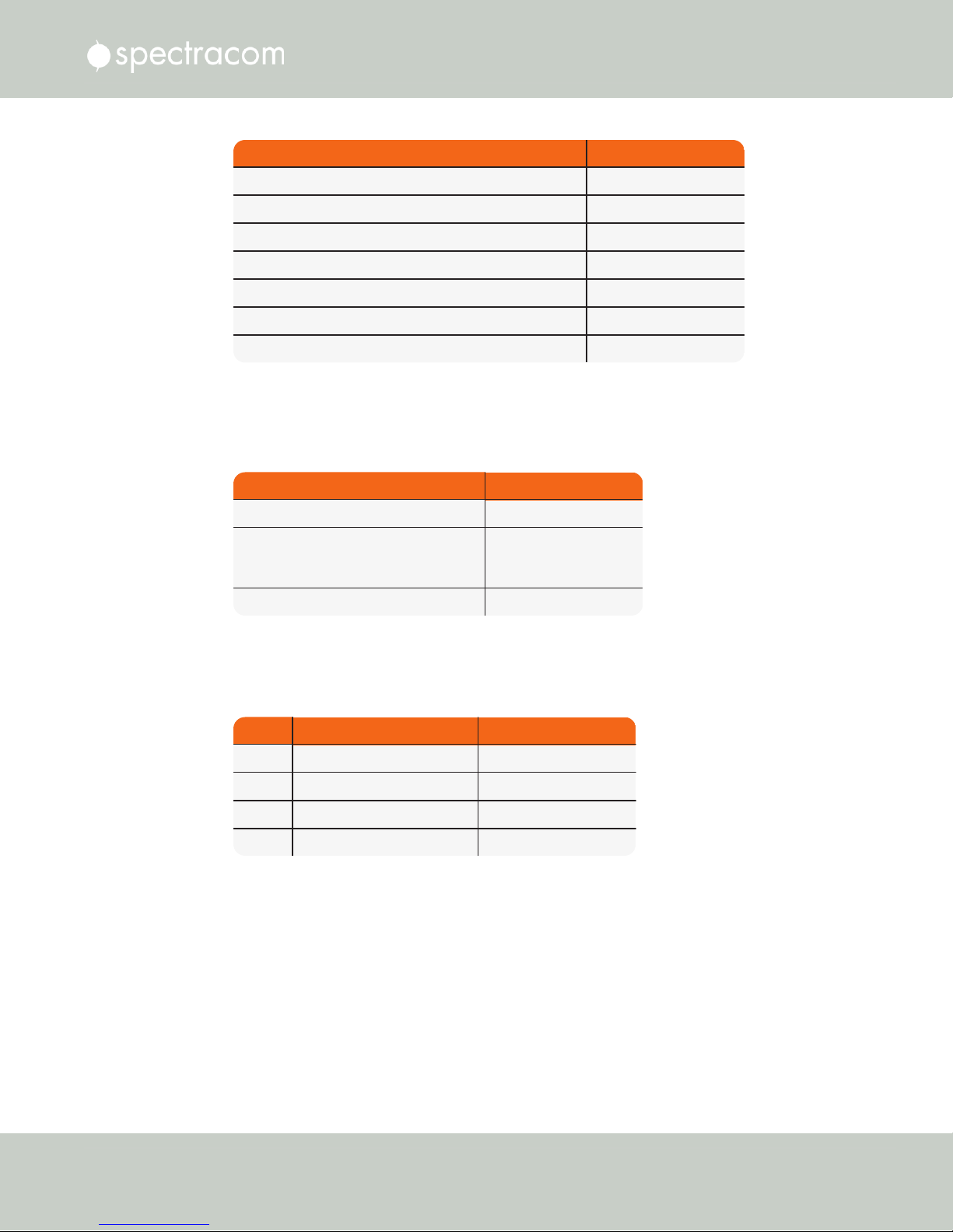
Type Connector
(1) Ethernet 10/100Base-T RJ-45 (auto-sensing)
(1) RS-232 Serial Connector DB9 female
(1) RS-485 Once-per-Second 3.81 mm Terminal Block
(1) IRIG B/E, IEEE 1344/C37.118-2005 (AM/TTL) output BNC
(1) 1 Pulse Per Second (1PPS) output BNC
(1) 10 MHz Frequency output BNC
(2) Relay / Alarm Outputs 3.81 mm Terminal Block
1.5.2 NetClock 9483: Optional Outputs
Type Connector
(3) 10/100/1000Base-T [Multi-Ethernet] RJ-45 (auto-sensing)
(1) 1.544 or 2.048 MHz
(2) 1.544 or 2.048 MHz
[T1/E1 Balanced]
3.81 mm Terminal Block
(1) PTP (IEEE 1588) RJ-45
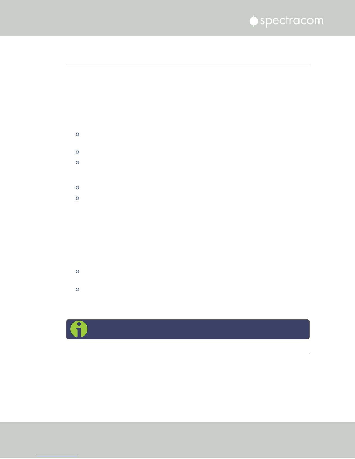
I/O Type Connector
I/O (1) Ethernet 10/100Base-T RJ-45 (auto-sensing)
Output (1) 1 Pulse Per Second (1PPS) BNC
Outputs (2) RS-485 Once-per-Second 3.81 mm Terminal Block
Input (1) RS-485 Once-per-Second 3.81 mm Terminal Block
Several Option Modules are available for NetClock 9483, providing additional outputs and
functionality:
1.5 Inputs & Outputs
For more information, see "NetClock 9483 Option Modules" on page335.
1.5.3 NetClock 9489 Standard Inputs and Outputs
For more information, see "NetClock 9489 In-/Outputs" on page336.
CHAPTER 1 • NetClock User Reference Guide Rev. 16
5
Page 22
1.6 NetClock 9400 Series Front Panels
1.6 NetClock 9400 Series Front Panels
1.6.1 NetClock 9483 Front Panel
Figure 1-1: NetClock 9483 Series Front Panel Display
The front panel of the NetClock 9483 unit consists of the following:
Three Status LED indicator lights (“Power”, “Sync” and “Fault”); see also "Status LEDs" on
page8.
Keypad buttons, for performing operations from the front panel.
LCD display, showing status information or currently selected menu items (display
options are configurable via the product web interface, such as position information,
time and date, Day of Year, GPS information, network settings, etc.).
LED time display.
An RS-232 serial port interface for serial cable connections.
1.6.2 NetClock 9489 Front Panel
Figure 1-2: NetClock 9489 Front Panel
The front panel of the NetClock 9489 unit consists of the following:
Three Status LED indicator lights (“Power”, “Sync” and “Fault”). See also "Status LEDs"
on page8.
An RS-232 serial port interface connection.
1.6.3 Front Panel Keypad, and Display
Note: This Section applies to NetClock 9483 only.
To simplify operation and to allow local access to NetClock, a keypad and a 4-line LCD inform
ation display are provided on the front panel of the unit.
The front panel keypad and display can be used to configure basic network settings e.g., en/disabling DHCP, or setting an IP address and subnet mask.
6
CHAPTER 1 • NetClock User Reference Guide Rev. 16
Page 23

Note: If the keypad be locked, see "Troubleshooting – Keypad Is Locked" on
page331.
1.6.3.1 Using the Keypad
The functions of the six keys are:
tu arrow keys: Navigate to a menu option (will be highlighted)
pq arrow keys: Scroll through parameter values in edit displays
1.6 NetClock 9400 Series Front Panels
ü ENTER key: Select a menu option, or load a parameter when editing
Ò BACK key: Return to previous display or abort an edit process
1.6.3.2 Navigating the Front Panel Display
After power initialization, press any key to go to the “Home” display. As shown in the illus
tration "Front panel menu tree" on the next page, several status and setup displays are access
ible from the main “Home” menu. To navigate through the menus, use the arrow keys to
highlight a selection and then press the ENTER button.
The main menu options and their primary functions are as follows:
Display: Used to configure the information display
Clock:Displaying and setting of the current date and time
System:Displaying version info, system halt and reboot, reset spadmin password
Netv4:Network interface configuration
Lock: Locks the front panel keypad to prevent inadvertent operation.
Front Panel Display: Menu Tree
The illustration below shows how the menu is organized, and which functions can be accessed
via the front panel (i.e. without using the Web UI):
CHAPTER 1 • NetClock User Reference Guide Rev. 16
7
Page 24

1.6 NetClock 9400 Series Front Panels
Figure 1-3: Front panel menu tree
To modify a parameter:
Highlight the menu option and press the ENTER button.
“O” stands for current old setting, and “N” is the new setting.
You can only change the “N” setting.
Use the UP and DOWN arrow keys to scroll through all possible parameter values.
To edit a sequence of numbers:
Use the LEFT and RIGHT arrow keys to select other digits. Once the desired parameter is
displayed, press ENTER to make the new value the current ("O") value. You will be asked
to confirm the setting change. Press ENTER to accept or BACK to cancel the parameter
change.
All entered values are stored in the unit's non-volatile memory and will be restored after a
power cycle.
1.6.4 Status LEDs
Three Status LEDs, located on the unit's front panel, indicate NetClock's current operating status:
POWER: Green, always on while power is applied to the unit
SYNC: Tri-color LED indicates the time data accuracy
FAULT: Two-color, three-state LED, indicating if any alarms are present.
At power up, the unit automatically performs a brief LED test run during which all three LEDs
are temporarily lit.
8
CHAPTER 1 • NetClock User Reference Guide Rev. 16
Page 25

LED Label Activity/Color Description
POWER
Off Both AC, and DC input power are disconnected.
OR: The unit's AC input switch is turned OFF, and DC input is not
present.
On/solid
green
AC and/or DC Power are supplied; the unit detects all power
inputs.
Red
The unit is configured for two power inputs, but detects only one
power input. OR:Detects a power configuration error.
Green
& blinking
orange
1/sec.
Power Error — general power configuration fault.
SYNC
Red
Time Sync Alarm:
1) The unit has powered up, but has not yet achieved syn
chronization with its inputs.
2) The unit was synchronized to its selected input references, but
has since lost all available inputs (or the inputs were declared
invalid) and the Holdover period has since expired.
Solid
green
The unit has valid time and 1PPS reference inputs present and is syn
chronized to its reference.
Orange
The unit is in Holdover Mode: It was synchronized to its selected
input references, but has since lost all available inputs (or the inputs
are not declared valid).The time and frequency outputs will remain
useable until the Holdover period expires.
FAULT
Off No alarm conditions are currently active.
Blinking
orange
A GNSS antenna alarm has been asserted and is currently active.
A short or open circuit has been detected in the GNSS antenna
cable. The light will automatically turn off once the alarm condition
clears.
To troubleshoot this condition, see
"Troubleshooting via Web
UI Status Page" on page328
.
Solid
orange
A Minor Alarm condition (other than an antenna problem alarm)
has been asserted and is currently active.
To troubleshoot this condition, see
"Minor and Major Alarms"
on page325
.
Red
A Major Alarm condition has been asserted and is currently active.
To troubleshoot this condition, see
"Minor and Major Alarms"
on page325
.
1.6 NetClock 9400 Series Front Panels
Table 1-1:
Front panel status indications
CHAPTER 1 • NetClock User Reference Guide Rev. 16
9
Page 26

Ethernet
Yellow
ON LAN activity detected.
OFF No LAN activity detected
Ethernet
Green
ON LAN link established, 10 or 100 Mb/s.
OFF No link established.
1.7 NetClock 9400 Series Rear Panels
1.7 NetClock 9400 Series Rear Panels
1.7.1 NetClock 9483 Rear Panel
The NetClock 9483 rear panel provides several different outputs for interfacing the unit to vari
ous systems. The rear panel has an ACconnection for power input (DCPower is optional), Eth
ernet and USB connections, 1PPS and 10MHz outputs, IRIG, ASCII, and Relay/Alarm outputs,
and GPS Antenna connector.
Figure 1-4: NetClock 9483 rear panel
AC power connector: Input for the AC power and provides and AC power ON/OFF
switch. This connector is only installed if NetClock was ordered with AC input power
option.
DC power port connector: Only installed if the NetClock was ordered with DC input
power option. Note: DC input power does not have an ON/OFF switch.
Ethernet connector: Provides an interface to the network for NTP synchronization and to
obtain access to the NetClock product web interface for system management. It has two
small indicator lamps, “Good Link” (green LED), and “Activity” (orange LED). The “Good
Link” link light indicates a connection to the network is present. The “Activity” link light
will illuminate when network traffic is detected.
Table 1-2:
Status indicators, rear panel
10
CHAPTER 1 • NetClock User Reference Guide Rev. 16
Page 27
1.7 NetClock 9400 Series Rear Panels
USB connector is reserved for future expansion.
1PPS output: Provides a once-per-second square-wave output via BNC output connector.
The 1PPS output can be configured to have either the rising or falling edge of the signal
to be coincident with the system’s on-time point.
10 MHz output: Provides a 10 MHz sine-wave output via BNC output connector.
IRIG output: Supports IRIG A/B/G/E, IEEE 1344/C37.118-2005 (AM/TTL).
RS-232 output: for serial connections.
Relay/Alarm outputs.
GNSS antenna connector: GNSS input for GNSSS antenna and coax cabling (type “N”
connector).
RS-485 output for serial connection.
Note: The pin numbers for the RS-485 outputs are defined starting with
Pin1 to Pin10, arranged from left to right, as shown below:
Figure 1-5: Rear panel of NENA-compliant module (NetClock 9483)
1.7.2 NetClock 9489 Rear Panel
The NetClock 9489 rear panel provides:
an AC connection for power input
an Ethernet port
(1) 1PPS output
(2) RS-485 ASCIIoutputs, and (1) RS-485 input
a GNSS antenna connector.
CHAPTER 1 • NetClock User Reference Guide Rev. 16
11
Page 28

1.7 NetClock 9400 Series Rear Panels
Figure 1-6: Rear panel of NetClock model 9489
The pinout description for the RS-485 connector can be found under "NetClock 9489 In-/Out
puts" on page336.
12
CHAPTER 1 • NetClock User Reference Guide Rev. 16
Page 29

1.8 NetClock 9483—Available Option Modules
1.8 NetClock 9483—Available Option Modules
NetClock 9483 models can be customized and enhanced via the addition of up to two (2) addi
tional option modules, detailed in this section.
Note: In some cases, the number of option modules of any one type that can be
installed may be limited (see “Maximum number of cards” for each type of mod
ule).
For additional information on available option modules, including configuration and usage,
see also "NetClock 9483 Option Modules" on page335.
1.8.1 T1 (1.544 MHz) and E1 (2.048 MHz) Module
Outputs:
T1 mode:
1.544 MHz (square wave) frequency output
(2) 1.544 Mb/sec data rate outputs:
Outputs are DS1 framed all ones.
Supports Super Frame (SF or D4) and Extended Super Frame (ESF).
SSM support.
E1 mode:
2.048 MHz (square wave) frequency output
(2) 2.048 Mb/sec data rate outputs:
Outputs are E1 frame all ones.
Supports CRC4 and CAS Multiframe.
SSM support.
Maximum Number of Cards: 1
Ordering Information:
Option 13: T1/E1 Balanced
(1) E1 (75 Ω) module
(2) T1 and E1 (100/120 Ω) module
1.8.2 Multi-Port Gigabit Ethernet Module
Inputs/Outputs: (3) Gigabit Ethernet (10/100/1000 Base-T)
Signal Type and Connector: RJ-45
CHAPTER 1 • NetClock User Reference Guide Rev. 16
13
Page 30

1.8 NetClock 9483—Available Option Modules
Management: Enabled or Disabled (NTP server only)
Maximum Number of Cards: 4
Ordering Information: Option 16: Multi-port Ethernet (3X) Module
14
CHAPTER 1 • NetClock User Reference Guide Rev. 16
Page 31

1.9 The NetClock Web UI
NetClock has an integrated web user interface (referred to as "WebUI" throughout this doc
umentation) that can be accessed from a computer over a network connection, using a standard
web browser. The WebUI is used to configure the unit, and for status monitoring during every
day operation.
Note: An integrated Command-Line Interpreter interface (CLI) allows the use of a
subset of commands that are integrated into the Web UI.
The minimum browser requirements for the Web UI are: Internet Explorer®9 or higher,
Firefox®, or Chrome®.
Note: Should it ever be necessary, you can restore NetClock's configuration to
the factory settings at any time. See "Resetting the Unit to Factory Configuration"
on page313.
1.9 The NetClock Web UI
1.9.1 The Web UI HOME Screen
Note: Screens displayed in this manual are for illustrative purposes. Actual
screens may vary depending upon the configuration of your product.
The HOME screen of the NetClock web user interface ("Web UI") provides comprehensive
status information at a glance, including:
vital system information
current status of the references
key performance/accuracy data
major log events.
The HOMEscreen can be accessed from anywhere in the Web UI, using the HOMEbutton in
the Primary Navigation Bar:
CHAPTER 1 • NetClock User Reference Guide Rev. 16
15
Page 32

1.9 The NetClock Web UI
The Primary Navigation Bar provides access to all menus:
HOME: Return to the HOME screen (see above)
INTERFACES: Access the configuration pages for …
… references (e.g., GNSS, NTP)
… outputs (e.g. 10 MHz, PPS, NTP) and
… installed input/output option cards.
MANAGEMENT: Access the NETWORK setup screens, and OTHER setup screens e.g., to
configure Reference Priorities, System Time, and the Oscillator.
TOOLS: Opens a drop-down menu for access to the system maintenance screens and sys
tem logs.
HELP: Provides Spectracom Service Contact Information and high-level system con
figurations you may be required to furnish when contacting Spectracom Service.
1.9.2 The INTERFACES Menu
The INTERFACES menu on the Main screen provides access to NetClock's:
External REFERENCES e.g., the GNSS reference input
Detected OUTPUTS, such as 10 MHz and 1PPS
Installed OPTIONS.
16
CHAPTER 1 • NetClock User Reference Guide Rev. 16
Page 33

1.9 The NetClock Web UI
Clicking on any of the line items will open a status screen, providing real-time information on
the selected interface e.g., availability, performance data and events history.
To configure settings for the selected interface, click the GEAR icons or buttons provided on
most of the status screens. Icons like the INFO symbol provide access to more detailed status
information and history data.
Note: Many of the interfaces can be accessed through different menu items e.g.,
an optional output will be available under the OPTION CARDS menu and the
OUTPUTS menu.
The headings of each of the INTERFACES drop-down menus (white on orange) open overview
status screens for the respective menu items.
1.9.3 The Configuration MANAGEMENT Menu
The MANAGEMENT menu on the Web UI's Main screen provides access to NetClock's con
figuration screens and settings.
On the left side, under NETWORK, the following standard setup screens can be found:
Network Setup
General Setup
HTTPS Setup
CHAPTER 1 • NetClock User Reference Guide Rev. 16
17
Page 34

1.9 The NetClock Web UI
SSH Setup
SNMP Setup
NTP Setup
PTP Setup
PeerD Setup.
Under OTHER, you can access non-network related screens:
Authentication: Manage user accounts, Security Policy, LDAP Setup, RADIUS setup,
Login Preference and Remote Servers. Change My Password is also available.
Reference Priority: Define the order of priority for timing inputs.
Notifications: Configure the notifications triggered by NetClock’s events. A notification
can be a combination of a mask alarm and/or SNMP Trap and/or email.
Time Management: Manage the Local Clock, UTC Offset, DST Definition and Leap
Second information.
Front Panel: Configure the appearance of the NetClock front panel display and keypad.
Log Configuration: Manage the system logs.
Disciplining: Manage oscillator disciplining.
Change My Password: Configure the admin password.
1.9.4 The TOOLS Menu
The TOOLS menu on the Web UI's Main screen provides access to:
The System Upgrade screen
System and network monitoring screens
Miscellaneous system administration screens
Log screens
18
CHAPTER 1 • NetClock User Reference Guide Rev. 16
Page 35

1.10 Specifications
The specifications listed below apply to the base NetClock 9483 model, i.e. not including any
option modules, and are based on “normal” operation, with NetClock synchronized to valid
Time and 1PPS input references (in the case of GNSS input, this is with the GNSS receiver oper
ating in Stationary mode).
Specifications for the available option modules are provided in their corresponding topics; see
"NetClock 9483 Option Modules" on page335.
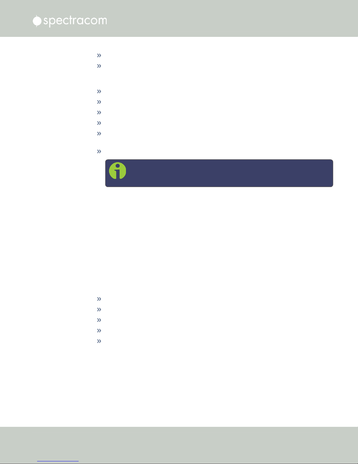
1.10.1 Input Power
AC power source:
100 to 240 VAC, 50/60 Hz, ±10 % and
100-120 VAC400 Hz, ±10% via an IEC 60320 connector (power cord included)
DC input (option):
12-17 VDC-15%, +20%, or
1.10 Specifications
Maximum power draw:
1.10.1.1 Fuses
Type: T 2A L 250V
Model:
Number: 2 (two) per unit
NetClock label on rear panel of unit:
21-60 VDC-15%, +20%, secure locking device
Note: The DC power option is available only for NetClock Model 9489.
TCXO/OCXO oscillator installed: 40 W normal (50 W start-up)
Rubidium (Rb) oscillator installed: 50 W normal (80 W start-up)
Spectracom recommends: LITTELFUSE 0213002.MXP
[Spectracom part number: F010R-0002-000 E FUSE,2A,SB,IECSURGE,GLASS]
CHAPTER 1 • NetClock User Reference Guide Rev. 16
19
Page 36

1.10 Specifications
"AC POWER/F 2A T 250V (2)"
LEGEND:
F = Fuse
2A = Current Rating: 2 Ampères
T = Speed: Time Delay (Slow-Blow)
L = Breaking Capacity: Low (Glass)
250V = Voltage Rating
(2) = Fuses used: 2 (two)
Caution: Before testing fuses, remove ACpower by disconnecting the AC power
cord.
Note: In the event that the unit does not power up with AC power, these fuses
should be tested.
1.10.2 GNSS Receiver
Model: u-blox M8T
Compatible signals:
GPS L1 C/A Code transmissions at 1575.42 MHz
GLONASS L10F transmissions centered at 1602.0 MHz
Galileo E1 B/C transmissions at 1575.42 MHz
BeiDou B1 transmissions centered at 1561.098 MHz
QZSS L1-SAIF transmissions at 1575.42 MHz
Satellites tracked: Up to 72 simultaneously
Update rate: up to 2Hz (concurrent)
Acquisition time: Typically <27seconds from cold start
Antenna requirements : Active antenna module, +5V, powered by NetClock, 16dB gain min
imum
Antenna connector: Type N, female
1.10.3 RS-232 Serial Port (Front Panel)
Function: Accepts commands to locally configure the IP network parameters via CLI for initial
unit configuration.
Connector: DB9F, pin assignments conform to EIA/TIA-574, data communication equipment
20
CHAPTER 1 • NetClock User Reference Guide Rev. 16
Page 37

Character structure: ASCII, 9600 baud, 1 start, 8 data, 1 stop, no parity
1.10.4 RS-232 Serial Port (Rear Panel; NetClock 9483 Only)
Outputs: RS-232, ASCII time code data input/output; 1PPS output.
Connector: DB9F
Accuracy: ±100-1000 μs (format-dependent)
1.10.5 RS-485 Serial Port
Outputs: RS-485, and Alarm/Relay (NetClock 9483 only)
Signal Type and Connector: (1) RS-485 terminal block
Accuracy: ±100-1000 μs (format-dependent)
1.10.6 10/100 Ethernet Port
1.10 Specifications
Function : 10/100 Base-T, auto- sensing LAN connection for NTP/SNTP and remote man
agement and configuration, monitoring, diagnostics and upgrade
Connector: RJ-45, Network IEEE 802.3
1.10.7 IRIG Output (NetClock 9483 Only)
Outputs: (1) IRIG Output
Signal Type and Connector: IRIG A, B, G, E, NASA 36, Amplitude Modulated (0V to
5V
into 50 Ω on BNC) or DC Level Shift (unmodulated), user selectable.
P-P
Accuracy: ±2 to 200 microseconds (IRIG Format-dependent)
1.10.8 Protocols Supported
NTP : NTP Version4 (Installed: Version 4.2.8p8). Provides MD5, Stratum1 through 15 (RFC
5905). Note that NTP Autokey is currently not supported, for more information, see
http://bugs.ntp.org/show_bug.cgi?id=3005.
NTP throughput: ETH0: 7000-7200 NTP requests per second; ETH1-ETH3 (NetClock 9483 only:
equipped with 1204- 06/Option16 Gigabit Ethernet Option Module) : 8800- 9000 NTP
requests per second. For additional information, please contact Spectracom.
Clients supported: The number of users supported depends on the class of network and the sub
net mask for the network. A gateway greatly increases the number of users.
TCP/IP application protocols for browser-based configuration and monitoring: HTTP, HTTPS
FTP/SFTP: For remote upload of system logs and (RFC 959)
Syslog: Provides remote log storage (RFCs 3164 and 5424)
SNMP: Supports v1, v2c, and v3
CHAPTER 1 • NetClock User Reference Guide Rev. 16
21
Page 38

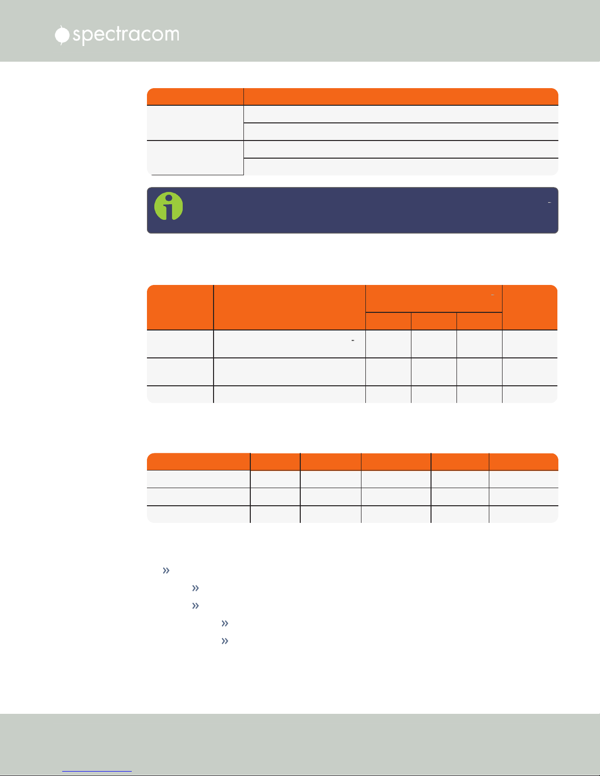
Oscillator Type
Accuracy to UTC
(1 sigma locked to GPS)
Holdover (constant temp. after 2weeks of GPS lock)
After 4 hours After 24 hours
Rubidium ±25 ns 0.2 μs 1μs
Standard OCXO ±50 ns 1μs 25 μs
TCXO ±50 ns 12 μs 450 μs
Oscillator Type Accuracy
Rubidium 1x10
-12
typical 24-hour average locked to GPS
1x10
-11
per day (5x10
-11
per month) typical aging unlocked
1.10 Specifications
Telnet/SSH: For limited remote configuration
Security features : Up to 32-character password, Telnet Disable, FTP Disable, Secure SNMP,
SNMP Disable, HTTPS/HTTP Disable, SCP, SSH, SFTP.
Authentication: LDAP v2 and v3, RADIUS, MD5 Passwords, NTP Autokey protocol.
1.10.9 1PPS Output
Signal: One pulse-per-second square wave (ext. reference connected to GNSS receiver)
Signal level: TTL compatible, 4.3 V minimum, base-to-peak into 50 Ω
Pulse width: Configurable pulse width (200 ms by default)
Pulse width range: 20 ns to 900 ms
Rise time: <10 ns
Accuracy: Positive edge within ±50 ns of UTC when locked to a valid 1PPS input reference
Connector: BNC female
Table 1-3:
1PPS output accuracies
1.10.10 10 MHz Output (NetClock 9483 Only)
Signal: 10 MHz sine wave
Signal Level: +13 dBm ±2dB into 50 Ω
Harmonics: ˗40 dBc minimum
Spurious: ˗70 dBc minimum TCXO
Connector: BNC female
Signature Control: This configurable feature removes the output signal whenever a
major alarm condition or loss of time synchronization condition is present. The output
will be restored once the fault condition is corrected.
Table 1-4:
10 MHz output — oscillator types and accuracies
22
CHAPTER 1 • NetClock User Reference Guide Rev. 16
Page 39
Oscillator Type Accuracy
Standard OCXO 2x10
-12
typical 24-hour average locked to GPS
1x10⁻⁹per day typical aging unlocked
TCXO 1x10
-11
typical 24-hour average locked to GPS
1x10⁻⁸per day typical aging unlocked
Note: Oscillator accuracies are stated as fractional frequency (i.e. the relative fre
Oscillator Type
Medium-Term Stability
(without GPS after 2 weeks of GPS
lock)
Short-Term Stability (Allan vari
ance)
Temperature
Stability
(p˗p)
1sec. 10sec. 100 sec.
Rubidium 5x10
-11
/month (3x10
-11
/month typ
ical)
2x10
-11
2x10
-12
2x10
-12
1x10
-10
Standard
OCXO
5x10
-10
/day 5x10
-10
5x10
-11
1x10
-11
5x10
-9
TCXO 1x10⁻⁸/day 2x10
-9
1x10
-9
3x10
-10
1x10
-6
Oscillator Type @ 1Hz @ 10Hz @ 100Hz @ 1KHz @ 10KHz
Rubidium ˗80 ˗98 ˗120 ˗140 ˗140
Standard OCXO ˗95 ˗123 ˗140 ˗145 ˗150
TCXO ./. ./. ˗110 ˗135 ˗140
quency departure of a frequency source), and as such are dimensionless.
See also "Configuring the Oscillator" on page215.
1.10 Specifications
Table 1-5:
10 MHz output — oscillator stability
1.10.10.1 10 MHz Output — Oscillator Phase Noise (dBc/Hz)
1.10.11 Mechanical and Environmental Specifications
Dimensions:
Designed for EIA 19” rack mount:
Housing w/o connectors and brackets:
16.75” W x 1.72” H [1U] x 14.33” D actual
(425 mm W x 44 mm H x 364 mm D)
CHAPTER 1 • NetClock User Reference Guide Rev. 16
23
Page 40

1.11 Regulatory Compliance
Weight:
Temperature:
Humidity:
Altitude:
6.0 lbs (2.72 kg)
6.5 lbs. (2.95 kg) with Rubidium oscillator option
Operating:
–20°C to +65°C (+55°C for Rubidium option [NetClock 9483 only])
Storage:
–40°C to +85°C
10% - 95% relative humidity, non-condensing @ 40°C
Operating:
100-240 VAC: up to 6560 ft (2000 m)
100-120 VAC: up to 13123 ft (4000 m)
12-17 VDCand 21-60VDC: up to 13125 ft (4000 m)
Storage range:
up to 45000 ft (13700 m)
Shock:
Operating: 15g/0.53 oz, 11ms, half sine wave
Storage: 50g/1.76 oz, 11ms, half sine wave
Vibration:
Operating: 10-55 Hz @ 0.07g
Storage: 10-55 Hz @ 0.15g²/Hz; 55-500 Hz @ 2.0g²/Hz
MIL-STD-810F: 501.4, 502.4, 507.4, 500.4, 516.5, 514.5
1.11 Regulatory Compliance
This product has been found to be in conformance with the following regulatory publications.
FCC
²
/Hz; 55-500 Hz @ 1.0g²/Hz
This equipment has been tested and found to comply with the limits for a ClassA digital
device, pursuant to Part15 of the FCC Rules.
These limits are designed to provide reasonable protection against harmful interference when
the equipment is operated in a commercial environment. This equipment generates, uses, and
24
CHAPTER 1 • NetClock User Reference Guide Rev. 16
Page 41

1.11 Regulatory Compliance
can radiate radio frequency energy and, if not installed and used in accordance with the user
documentation, may cause harmful interference to radio communications.
Operation of this equipment in a residential area is likely to cause harmful interference in
which case the user will be required to correct the interference at his/her own expense.
Safety
EN 60950-1:2006/A11:2009: Safety of Information Technology Equipment, including Elec
trical Business Equipment
This product has been tested and meets the requirements specified in:
UL 60950-1, 1st Edition
CSA C22.2 No. 60950-1-07, 2nd Edition
UL Listing no. E311040
EMC, CE:
EN 55022:2006/A1:2007: Class A: EC Emissions Standard
EN 55024:1998/A2:2003: EC Generic Immunity Standard
EN 61000-3-2:2006: Harmonic Current Emissions
EN 61000-3-3:1995/A2:2005: Voltage Fluctuations and Flicker
The product complies with the requirements of the Low Voltage Directive 2006/95/EC
and the EMC Directive 2004/108/EC.
Note: This is a Class A product. In a domestic environment this product
may cause radio interference in which case the user may be required to
take adequate measures.
EMC, ICES-003 and AS/NZS CISPR 22:
This Class (A) digital apparatus complies with Canadian ICES-003, Issue 4.
This Class (A) digital apparatus complies with AS/NZS CISPR 22 for radiated and con
ducted Emissions.
CHAPTER 1 • NetClock User Reference Guide Rev. 16
25
Page 42

1.11 Regulatory Compliance
BLANK PAGE.
26
CHAPTER 1 • NetClock User Reference Guide Rev. 16
Page 43

SETUP
The following topics are included in this Chapter:
2.1 Overview 28
2.2 Unpacking and Inventory 29
2.3 Required Tools and Parts 29
2.4 SAFETY 31
2.5 Mounting the Unit 34
2.6 Connecting Supply Power 36
2.7 Connecting the GNSS Input 40
2.8 Connecting Network Cables 40
2.9 Connecting Inputs and Outputs 41
2.10 Powering Up the Unit 41
2.11 Setting up an IP Address 42
2.12 Accessing the WebUI 53
2.13 Connecting Reference Inputs and Network Interface55
2.14 Configuring Network Settings 56
2.15 Configuring NTP 95
2.16 Configuring Input References 137
2.17 Configuring Outputs 137
CHAPTER 2
CHAPTER 2 • NetClock User Reference Guide
27
Page 44

2.1 Overview
2.1 Overview
This section provides an outline of the steps that need to be performed prior to putting NetC
lock into service. This includes:
The following factors determine which steps need to be taken:
a.
b.
c.
Installation: Hardware setup, mechanical installation, physical connections.
Setup: Establish basic access to the unit, so as to allow the use of the web user interface
("WebUI").
Configuration: Access the Web UI, configure the network, input and output references,
protocols (e.g., NTP), other settings.
The power source(s) your NetClock is configured for.
Your existing infrastructure and how you plan on integrating NetClock into it (for
example, integrating it into an existing Ethernet network, or setting-up a standalone
installation.)
How you would like to setup basic network configuration parameters:
Using the unit's front panel keypad and information display
Using a PC connected to NetClock via serial cable
Using a PC connected to NetClock via network cable.
You can connect your PC to NetClock either…
…directly by means of a dedicated Ethernet cable, or
…indirectly, using your existing Ethernet network (using a network hub).
d.
The options configuration of your unit: Is your NetClock equipped with any options? If
so, they need to be configured separately via the NetClock Web UI, once the network
configuration is complete.
2.1.1 Main Installation Steps
The following list is a recommendation. Deviations are possible, depending on the actual
application and system configuration.
1.
Unpack the unit, and take inventory: "Unpacking and Inventory" on the facing page.
2.
Obtain required tools and parts: "Required Tools and Parts" on the facing page.
3.
Mount the unit: ."Mounting the Unit" on page34.
4.
Read the Safety instructions: "SAFETY" on page31.
5.
Connect your power supply/-ies: "Connecting Supply Power" on page36.
6.
Connect Input References such as your GNSS antenna, and network cable(s): "Con
necting the GNSS Input" on page40, and "Connecting Network Cables" on page40.
28
CHAPTER 2 • NetClock User Reference Guide Rev. 16
Page 45

7.
Power up the unit: "Powering Up the Unit" on page224.
8.
Setup basic network connectivity…
i.
…via front panel keypad and information display (NetClock 9483 only): "Setting
Up an IP Address via the Front Panel" on page47
ii.
…or via serial port, using a PC with a CLI: "Setting Up an IP Address via the
Serial Port" on page50
iii.
…or via Ethernet, using a PC with a web browser, and the NetClock Web UI:
"Accessing the WebUI" on page53.
9.
Register your product: "Product Registration" on page265.
2.2 Unpacking and Inventory
Caution: Electronic equipment is sensitive to Electrostatic Discharge (ESD).
Observe all ESD precautions and safeguards when handling the unit.
2.2 Unpacking and Inventory
Unpack the equipment and inspect it for damage. If any equipment has been damaged in
transit, or you experience any problems during installation and configuration of your Spec
tracom product, please contact Spectracom (see "Technical Support" on page429.)
Note: Retain all original packaging for use in return shipments if necessary.
The following items are included with your shipment:
NetClock unit
QuickStart Guide (printed version), and CD "Timing Product Manuals"
Ancillary items (except for rack mounting items, the contents of this kit may vary based
on equipment configuration and/or regional requirements)
Purchased optional equipment; note that option modules listed on the purchase order
will be pre-installed in the unit.
2.3 Required Tools and Parts
Depending on your application and system configuration, the following tools and parts may be
required:
CHAPTER 2 • NetClock User Reference Guide Rev. 16
29
Page 46

2.3 Required Tools and Parts
Phillips screwdrivers to install the rack-mount ears, and to mount the unit in a 19"-rack
If you plan on using DC power Spectracom recommends an external ON/OFF switch.
Ethernet cables (see "Connecting Network Cables" on page40).
2.3.1 Required GNSS Antenna Components
Should you plan on using a GNSS reference with your NetClock, you will also need:
Spectracom LMR-400 antenna cable with N connectors
Spectracom outdoor GNSS antenna with mounting bracket
Spectracom GNSS antenna surge suppressor (recommended)
Spectracom GNSS antenna inline amplifier (optional for short cable lengths)
For antenna installation guidelines, see the separate documentation shipped with the antenna
components.
30
CHAPTER 2 • NetClock User Reference Guide Rev. 16
Page 47

2.4 SAFETY
2.4.1 Safety: Symbols Used
2.4 SAFETY
Table 2-1:
Symbol Signal word Definition
Safety symbols used in this document, or on the product
Potentially dangerous situation which may lead to personal
DANGER!
CAUTION!
CAUTION!
NOTE
MULTIPLE
POWER SOURCES
ESD
injury or death! Follow the instructions closely.
Caution, risk of electric shock.
Potential equipment damage or destruction!
Follow the instructions closely.
Tips and other useful or important information.
This equipment may contain more than one power source: Dis
connect AC
the cover to avoid electric shock.
Risk of Electrostatic Discharge! Avoid potential equipment
damage by following ESD Best Practices.
DCpower supply cords before removing
and
CHASSIS GROUND
Analog Ground
Recycle
2.4.2 SAFETY: Before You Begin Installation
This product has been designed and built in accordance with state-of-the-art standards and the
recognized safety rules. Nevertheless, its use may constitute a risk to the operator or install
ation/maintenance personnel, if the product is used under conditions that must be deemed
unsafe, or for purposes other than the product's designated use, which is described in the intro
ductory technical chapters of this guide.
CHAPTER 2 • NetClock User Reference Guide Rev. 16
This symbol is used for identifying the functional ground of an
I/O signal. It is always connected to the instrument chassis.
Shows where the protective ground terminal is connected
inside the instrument. Never remove or loosen this screw!
Recycle the mentioned components at their end of life. Follow
local laws.
31
Page 48

2.4 SAFETY
DANGER! If the equipment is used in a manner not specified by the manufacturer,
the protection provided by the equipment may be impaired.
Before you begin installing and configuring the product, carefully read the following important
safety statements. Always ensure that you adhere to any and all applicable safety warnings,
guidelines, or precautions during the installation, operation, and maintenance of your product.
DANGER! — INSTALLATION OF EQUIPMENT:
Installation of this product is to be done by authorized service personnel
only.This product is not to be installed by users/operators without legal author
ization.
Installation of the equipment must comply with local and national electrical codes.
DANGER! — DONOTOPENEQUIPMENT, UNLESSAUTHORIZED:
The interior of this equipment does not have any user serviceable parts. Contact
Spectracom Technical Support if this equipment needs to be serviced. Do not
open the equipment, unless instructed to do so by Spectracom Service personnel.
Follow Spectracom Safety Instructions, and observe all local electrical regulatory
requirements.
DANGER! – IF THE EQUIPMENT MUST BE OPENED:
Never remove the cover or blank option card plates with power
applied to this unit. The unit may contain more than one power source. Dis
connect AC and DCpower supply cords before removing the cover to avoid elec
tric shock.
DANGER! — FUSING:
The equipment has Double Pole/Neutral Line Fusing on AC power.
32
CHAPTER 2 • NetClock User Reference Guide Rev. 16
Page 49

For continued protection against risk of fire, replace fuses only with same type
and rating of fuse.
DANGER! — GROUNDING: This equipment must be EARTHGROUNDED. Never
defeat the ground connector or operate the equipment in the absence of a suit
ably installed earth ground connection. Contact the appropriate electrical inspec
tion authority or an electrician if you are uncertain that suitable grounding is
available.
The AC and DC power connectors of this equipment have a connection to the
earthed conductor of the AC and DC supply earthing conductor through the AC
and DC power cords. The AC source outlet must contain a protective earthing con
nection. This equipment shall be connected directly to the AC power outlet earth
ing pin or DC supply system earthing electrode conductor.
The DC supply source is to be located within the same premises as this equipment:
The equipment shall be located in the same immediate area (such as, adjacent
cabinets) as any other equipment that has a connection to the earthing conductor
of the same AC or DC supply circuit earthing conductor, and also the point of
earthing of the AC or DC system.The AC or DC system shall not be earthed else
where.
2.4 SAFETY
Switches or other disconnection devices shall not be in the earthed circuit con
ductor between the AC and DC source and the point of the connection of the
earthing electrode conductor to NetClock’s AC and DC input power connectors
earthing pin.
DANGER! — BATTERY: Replace the battery only with the same or equivalent type
recommended by the manufacturer. Follow Spectracom Instructions — there is a
danger of a new battery exploding if it is incorrectly installed. Discard used bat
teries according to the manufacturer's instructions.
Caution: Electronic equipment is sensitive to Electrostatic Discharge (ESD).
Observe all ESD precautions and safeguards when handling Spectracom equip
ment.
CHAPTER 2 • NetClock User Reference Guide Rev. 16
33
Page 50

2.5 Mounting the Unit
2.4.3 SAFETY: User Responsibilities
The equipment must only be used in technically perfect condition. Check components for
damage prior to installation. Also check for loose or scorched cables on other nearby
equipment.
Make sure you possess the professional skills, and have received the training necessary
for the type of work you are about to perform.
Do not modify the equipment.
Use only spare parts authorized by Spectracom.
Always follow the instructions set out in this User Reference Guide, or in other Spec
tracom documentation for this product.
Observe generally applicable legal and other local mandatory regulations.
2.4.4 SAFETY: Other Tips
Keep these instructions at hand, near the place of use.
Keep your workplace tidy.
Apply technical common sense: If you suspect that it is unsafe to use the product, do the
following:
Disconnect the supply voltage from the unit.
Clearly mark the equipment to prevent its further operation.
2.5 Mounting the Unit
NetClock units can be operated on a desktop or in a rack in a horizontal, right-side-up pos
ition. The location needs to be well-ventilated, clean and accessible.
2.5.1 Rack Mounting
If installing the unit in a rack, install the rack-mount ears on the two sides of the front panel and
mount the unit in a standard 19-inch rack cabinet. The unit is intended to be installed in one ori
entation only. The unit should be mounted so the front panel interface keys are to the left of the
display area.
The NetClock unit will install into any EIA standard 19-inch rack. NetClock occupies one rack
unit of space for installation, however, it is recommended to leave empty space of at least one
rack unit above and below the NetClock unit to allow for best ventilation.
34
CHAPTER 2 • NetClock User Reference Guide Rev. 16
Page 51

2.5 Mounting the Unit
Rack mounting requirements:
The maximum ambient operating temperature must be observed. See for the operating
temperature range specified for the type of oscillator installed in your NetClock unit.
If the NetClock unit is to be installed in a closed rack, or a rack with large amounts of
other equipment, a rack cooling fan or fans should be part of the rack mount install
ation.
Installation of the unit in a rack should be such that the amount of air flow required for
safe operation of the equipment is not compromised.
Follow the mounting directions described below to prevent uneven mechanical loading,
possibly resulting in a hazardous condition.
Do not overload power supply circuits. Use only supply circuits with adequate overload
protection. For power requirements, see "Input Power" on page19.
Reliable grounding of rack-mounted equipment must be maintained. Particular attention
must be given to supply connections other than direct connections to the branch circuit
(e.g., use of power strips).
The NetClockancillary kit contains the following parts needed for rack mounting:
2 each 1165-1000-0714 rack mounting brackets
2 each MP09-0003-0030 equipment rack handles
4 each H020-0832-0406 #8-32 flat head Phillips screws
6 each HM20R-04R7-0010 M4 flat head Phillips screws
The following customer supplied items are also needed:
4 each #10-32 pan head rack mount screws
1 each #2 Phillips head screwdriver
1 each 3/32" straight screwdriver
To rack mount the NetClock unit:
1.
Attach an MP09-0003-0030 equipment rack handle to the front of each 1165-10000714 rack mounting bracket, using the holes nearest the right angle bend of the 11651000-0714 rack mounting bracket, with the #2 size Phillips screwdriver, using 2 each of
the H020-0832-0406 #8-32 flat head Phillips screws.
2.
Attach the 1165-1000-0714 rack mount brackets to the sides of the NetClock with the
rack mounts ears facing outward, aligned with the front edge of the NetClock front
panel. Use the #2 Phillips screwdrivers, using 3 each of the HM20R-04R7-0010 M4 flat
head Phillips screws.
3.
Secure the rack mount brackets to the rack using the #10-32 rack mount screws and #2
Phillips head screwdriver, 2 each per side of the rack.
CHAPTER 2 • NetClock User Reference Guide Rev. 16
35
Page 52
2.6 Connecting Supply Power
Caution: For safety reasons the NetClock unit is intended to be operated in a
HORIZONTAL POSITION, RIGHT-SIDE-UP, that is with the keypad to the left side
and the 4-line information display and the time display on the right side.
2.6 Connecting Supply Power
This section includes details on the NetClock’s AC and/or DC power systems (Note : The
DCpower option is available with NetClock 9483 only).
Depending on the equipment configuration at time of purchase, NetClock can be powered
from:
an AC input
a DC input
with both AC, and DC input (DC input is an option for NetClock 9483 units only).
Supplying both AC and DC input power provides redundant and automatic power switchover
in case one or the other input power sources is lost.
Before connecting power to the unit, be sure that you have read all safety information detailed
in section "SAFETY" on page31.
2.6.1 Power Source Selection
Note: Applies to NetClock 9483 only.
If both an AC, and a DC power source are connected to the unit, the following rules apply:
If AC and DC power are both applied, AC power is used.
If DC power is applied, but AC power is not, then DC power will be used.
If AC and DC power are both present, but AC power is subsequently lost, NetClock will
automatically switch to using the DC power input.
DANGER! — This unit will contain more than one power source if both the AC
and DC power options are present. Turning off the rear panel power switch will
NOT remove all power sources.
The following sections discuss AC and DC power input. Connect AC and/or DC power, as
required.
36
CHAPTER 2 • NetClock User Reference Guide Rev. 16
Page 53

2.6.2 Using AC Input Power
Connect the AC power cord supplied in the NetClock ancillary kit to the AC input on the rear
panel and the AC power source outlet. The AC input is fuse-protected with two fuses located in
the AC power entry module (line and neutral inputs are fused). The AC power entry module
also contains the main power switch for the AC power applied to the equipment.
Caution: This equipment has Double Pole/Neutral Line Fusing on AC power.
Note: Important! NetClock is earth grounded through the AC power connector.
Ensure NetClock is connected to an AC outlet that is connected to earth ground
via the grounding prong (do not use a two prong to three prong adapter to
apply AC power to NetClock).
2.6.3 Using DC Input Power (NetClock 9483 Only)
2.6 Connecting Supply Power
If the rear panel DC port is present, connect DC power, per the voltage and current as called
out on the label that resides above the DC power connector.
Note: DC power is an option chosen at time of purchase. The rear panel DC
input port connector is only installed if the DC input option is available. Different
DC power input options are available (12 VDCwith a voltage range of 12 to 17V
at 7A maximum or 24/48VDCinput with a voltage range of 21 to 60V at 3A
maximum). Review the DC power requirement chosen, prior to connecting DC
power (when the DC port is installed, a label will be placed over the connector
indicating the allowable DC input voltage range and the required current).
DANGER! GROUNDING: NetClock is earth grounded through the DC power con
nector. Ensure that the unit is connected to a DC power source that is connected to
earth ground via the grounding pin C of the NetClock DC power plug supplied
in the ancillary kit.
Caution: The DC input port is both fuse and reverse polarity protected. Reversing
polarity with the 24/48VDCoption will not blow the fuse, but the equipment will
not power- up. Reversing polarity with the 12VDCoption will likely blow the
internal fuse.
CHAPTER 2 • NetClock User Reference Guide Rev. 16
37
Page 54

2.6 Connecting Supply Power
A DC power connector to attach DC power to NetClock is included in the ancillary kit provided
with the equipment. A cable of 6feet or less, using 16AWG wire, with adequate insulation for
the DC voltage source should be used with this connector. The cable clamp provided with the
DC power plug for strain relief of the DC power input cable should be used when DC power is
connected to NetClock.
DC power connector pin-out
NetClock units can be ordered in a DC version that includes the following DC plug on the back
panel: DC Plug, 3-pin, chassis mount: Amphenol P/N DL3102A10SL-3P
Note: Spectracom recommends to use a dedicated DC power supply switch to
energize/de-energize NetClock externally.
The DC ancillary kit includes, among other things, the following connector parts:
Mating DC Connector, circular, 3-pin, solder socket, 16AWG,13A,300V: Amphenol
P/N DL3106A10SL-3S; (Spectracom part no. P240R-0032-002F)
Cable Clamp, circular: Amphenol part no. 97-3057-1004(621); (Spectracom part no.
Spectracom part no. MP06R-0004-0001)
38
CHAPTER 2 • NetClock User Reference Guide Rev. 16
Page 55

2.6 Connecting Supply Power
Pinout description, DC connector
Pin B goes to the most positive DC voltage of the DC source. For +12V or +24/48V this would
be the positive output from the DC source. For a -12V or -24/48VDCsource this would be the
ground or return of the DC source.
Pin A goes to the most negative voltage of the DC source. For +12V or +24/48V this would
be the ground or return output from the DC source. For a -12V or - 24/48VDCsource this
would be the negative output from the DC source.
Pin C goes to the Earth ground of the DC source.
AC/DC Converter
The DC input can be used as a second AC input: As an option, Spectracom offers a kit con
taining an AC/DC converter with a pre-assempled DC connector: The part number for this
adaptor kit is PS06R-2Z1M-DT01.
CHAPTER 2 • NetClock User Reference Guide Rev. 16
39
Page 56

2.7 Connecting the GNSS Input
2.7 Connecting the GNSS Input
1.
Install the GNSS antenna, surge suppressor, antenna cabling, and GNSS preamplifier
(if required). Refer to the documentation included with the GNSS antenna for additional
information regarding GNSS antenna installation.
2.
Connect the GNSS cable to the rear panel antenna input jack.
In the event that NO antenna is connected to the rear panel jack, NetClock will—once it
gets powered up (see "Powering Up the Unit" on page224)—activate the Antenna Prob
lem alarm, causing the front panel “Fault” light to be blinking orange (the Antenna Prob
lem alarm indicates an open or short exists in the antenna cable.)
Unless there is an open or short in the antenna cable, the "Fault" light should stop flash
ing orange once the GNSS antenna and coax cable are connected to the rear panel. If
the "Fault" light does not stop flashing after connecting the antenna, refer to
"Troubleshooting GNSS Reception" on page330.
Initial synchronization with GNSS input may take up to 5minutes (approximately) when used
in the default stationary GNSS operating mode. If using GNSS, verify that GNSS is the syn
chronization source by navigating to MANAGEMENT > OTHER: Reference Priority: Confirm
that GNSS is Enabled, and its Status for TIME and 1PPS is valid (green).
2.8 Connecting Network Cables
NetClock provides a base 10/100 Ethernet port for full NTP functionality, as well as a com
prehensive web-based user interface ("Web UI") for configuration, monitoring and diagnostic
support. Additional network ports are available with the Gigabit Ethernet option module.
First, you need to decide how you want to configure basic network connectivity e.g., the IP
address:
a.
Configure NetClock via the unit's front panel (NetClock 9483 only): See "Setting Up an
IP Address via the Front Panel" on page47.
If your unit does not have a front panel, see "Setting Up a Temporary IP Address
Remotely" on page51.
b.
Configure NetClock by means of a PC connected to an existing network.
When connecting to a hub, router, or network computer, use a straight-through
wired, shielded CAT 5, Cat 5E or CAT 6 cable with RJ-45 connectors. Connect
one end to the Ethernet port on the NetClock rear panel, and the opposite end of
the cable to a network hub or switch.
c.
Configure NetClock by connecting a stand-alone computer directly via a dedicated net
work cable (standard-wired, or crossover cable):
When connecting directly to a stand-alone PC, use a network cable. Connect the
cable to the NIC card of the computer.
Since no DHCP server is available in this configuration both NetClock, and the
PC must be configured with static IP addresses that are on the same subnet
40
CHAPTER 2 • NetClock User Reference Guide Rev. 16
Page 57

(10.1.100.1 and 10.1.100.2 with a subnet value of 255.255.255.0 on both
devices, for example).For more information on configuring static IP addresses,
see "Assigning a Static IP Address" on page44.
Once the unit is up and running, verify that the green link light on the Ethernet port is illu
minated. The amber “Activity” link light may periodically illuminate when network traffic is
present.
2.9 Connecting Inputs and Outputs
NetClock can synchronize not only to an external GNSS reference signal, but also to other
optional external references such as IRIG, HAVEQUICK and ASCII inputs (in addition to net
work based references such as NTP and/or PTP).
At the same time, NetClock can output timing and frequency signals for the consumption by
other devices via the same formats as listed above.
E X A M P L E :
2.9 Connecting Inputs and Outputs
With the available IRIG Input/Output option card module (Model 1204-05) installed in an option
bay, IRIG time code from an IRIG generator can also be applied as an external reference input (either
in addition to, or in lieu of GNSS, NTP, user set time and other available reference inputs).
To use e.g., an external IRIG reference, connect the IRIG time source to the BNC connector “J1”
on the optional IRIG Input/Output module. For additional information on optional connectivity,
such as pinout tables, signal levels and other specifications, see "Option Modules" on
page335.
Note that some option cards offer both input and output functionality, while others offer only
one or the other.
2.10 Powering Up the Unit
1.
After installing your NetClock unit, verify that power is connected, then turn ON the unit
using the switch on the rear panel, and wait for the device to boot up.
Note: NetClock 9483 only: DC input power is not switched, so NetClock
will be powered up with DC input connected, unless you installed an
external power switch.
2.
Observe that all of the front panel LEDs momentarily illuminate (the Power LED will then
stay lit) and that the Information display LCD back light illuminates. The fan may or may
not run, depending on the model year of your NetClock unit. For more information, see
CHAPTER 2 • NetClock User Reference Guide Rev. 16
41
Page 58

2.11 Setting up an IP Address
"Temperature Management" on page288.
NetClock 9483 only:
The time display will reset and then start incrementing the time. About 10 seconds after
power-up, “Starting up NetClock” will be displayed in the information display. After
approximately 2minutes, the information display will then show the current network set
tings.
By default, the 4-line information display shows the unit’s hostname, IPv4 address, mask,
and gateway.
The time display shows the current time: UTC (default), TAI, GPS or local timescale, as
configured.
Figure 2-1: NetClock front panel
3.
Check the front panel status LED indicators:
The Power lamp should be solid green.
The Sync lamp will probably be red, since synchronization has not yet been
achieved.
The Fault lamp will be OFF, or solid orange, indicating a minor alarm, or solid
red, asserting a power-up frequency error alarm (until the disciplining state is
reached.)
For additional information, see "Status LEDs" on page8 and "Status Monitoring via Front
Panel" on page266.
2.11 Setting up an IP Address
In order for NetClock to be accessible via your network, you need to assign an IP address to
NetClock, as well as a subnet mask and gateway, unless you are using an address assigned by
a DHCP server.
42
CHAPTER 2 • NetClock User Reference Guide Rev. 16
Page 59

2.11 Setting up an IP Address
Note: The setup process for NetClock 9489 (which has no front panel display
and keyboard) is described in "Setting Up a Temporary IP Address Remotely" on
page51.
There are several ways to setup an IP address, described below:
via the front panel keypad and information display
remotely …
…via serial cable
… via dedicated network cable
… via a DHCP network.
Before you continue …
… please obtain the following information from your network administrator:
Available static IP address
This is the unique address assigned to the NetClock unit by the network admin
istrator. Make sure the chosen address is outside of the DHCP range of your
DHCP server.
Note: The default static IP address of the NetClock unit is
10.10.201.x (x= dependent on ETH port).
Subnet mask (for the network)
The subnet mask defines the number of bits taken from the IP address that are used
in the network portion. The number of network bits used in the net mask can range
from 8 to 30bits.
Gateway address
The gateway (default router) address is needed if communication to the NetClock
is made outside of the local network. By default, the gateway is disabled.
Note: Make sure you are assigning a static IP address to your NetClock unit that
is outside of the DHCP range defined for the DHCP server. Your system admin
istrator will be able to tell you what this range is.
2.11.1 Dynamic vs. Static IP Address
On a DHCP network (Dynamic Host Configuration Protocol), NetClock's IP address will be
assigned automatically once it is connected to the DHCP server. This negotiated address and
CHAPTER 2 • NetClock User Reference Guide Rev. 16
43
Page 60

2.11 Setting up an IP Address
other network information are displayed on the unit front panel when the unit boots up.
If you plan on allowing your NetClock to use this negotiated DHCP Address on a permanent
basis, you can skip the following topics about setting up an IP address, and instead proceed to
"Accessing the WebUI" on page53, in order to complete the NetClock configuration process.
Please note:
Unless you are using DNS in conjunction with DHCP (with the client configured using NetC
lock's hostname instead of IP address), Spectracom recommends to disable DHCP for NetC
lock, and instead use a static IP address. Failure to do this can result in a loss of time
synchronization, should the DHCP server assign a new IPaddress to NetClock.
2.11.2 Assigning a Static IP Address
Spectracom recommends assigning a static IP address to NetClock, even if the unit is connected
to a DHCP server.
This can be accomplished in several ways:
a.
Via the keypad and information display on the front panel of the unit, see "Setting Up
an IP Address via the Front Panel" on page47. (NetClock 9483 only; If you are setting
up a NetClock 9489 unit – which does not have a front panel information display and
keypad – see "Setting Up a Temporary IP Address Remotely" on page51.)
b.
By connecting the NetClock to an existing DHCP network, temporarily using the
assigned DHCP address, see "Setting Up a Static IP Address via a DHCP Network" on
page49.
c.
By connecting a Personal Computer to NetClock via a serial cable, see "Setting Up an
IP Address via the Serial Port" on page50.
d.
By connecting a Personal Computer directly to NetClock via a dedicated Ethernet cable,
see "Setting up a Static IP Address via Ethernet Cable" on page51.
Note: For information on configuring routing tables, see "Static Routes" on
page64.
2.11.2.1 Assigning a New Static IP Address
To configure a NetClock unit that has not yet been assigned a custom IP address (e.g., because
your network does not support DHCP), there are two ways to enter the desired static IP
address, subnet mask, and gateway address:
The front panel keypad and its 4-line information display (NetClock 9483 only), or
a personal computer, connected to the NetClock unit via a serial cable, or via a ded
icated Ethernet cable.
44
CHAPTER 2 • NetClock User Reference Guide Rev. 16
Page 61

2.11 Setting up an IP Address
Note: Units are shipped with the default IP address of 10.10.201.1 with subnet
mask 255.255.255.0.
IMPORTANT NOTES:
On the NetClock 9489 unit DHCP is disabled by default.
As the NetClock 9489 does not include a front panel LCD that can display status information, it
is important to read the following sections carefully in order to successfully determine or con
figure a NetClock 9489‘s network settings. This can be achieved via one of the following meth
ods:
Configuration via serial cable connection
Configuration via crossover cable
Configuring a temporary IP address remotely.
Setting Up an IP Address via Serial Cable
The serial port can be used to make configuration changes (such as the network settings),
retrieve operational data (e.g., GNSS receiver information) and log files, or to perform oper
ations such as resetting the admin password.
For this task, you will need a serial cable, and a Personal Computer (PC) with a command-line
user interface program (CLI) installed on it, such as TeraTerm®, PuTTY®, or similar.
To configure an IP address via the serial port:
1.
Connect a pinned straight-thru standard DB9M to DB9F RS232 serial cable to a PC run
ning PuTTY, Tera Term, or HyperTerminal, and to your NetClock.
Use the following protocol parameters:
Bits per second: 9600
Data bits: 8
Parity: None
Stop bits: 1
Flow control: None
For more information on using the serial port connection, see "Setting up a Terminal
Emulator" on page381.
2.
The serial port is account and password protected. Login to NetClock with a user
account that has “admin” group rights, such as the default spadmin account (the
default password is admin123).
CHAPTER 2 • NetClock User Reference Guide Rev. 16
45
Page 62

2.11 Setting up an IP Address
Disable DHCP, type: dhcp4set 0 off <Enter>.
3.
Note: Users with “administrative rights” can perform all available com
mands. Users with “user” permissions only can perform get commands to
retrieve data, but cannot perform any set commands or change/reset
any passwords.
Note: If your NetClock is configured with an Ethernet option card, use 0,
1, 2, 3 for eth0 – eth3.
Note: For a list of CLI commands, type helpcli, or see "CLICommands"
on page382.
4.
Configure the IP address, subnet mask, and gateway (if needed):
ip4set 0 x.x.x.x y.y.y.y <Enter>
(where 0 is the desired interface, “x.x.x.x” is the desired IP address for NetC
lock, and “y.y.y.y” is the full subnet mask for the network (For a list of subnet
mask values, see "Subnet Mask Values" on page53.)
Enter gw4set 0 gw_address, using your gateway address gw_address.
5.
Once you have configured NetClock's IP address, you can login to the WebUI by enter
ing the new address into a web browser‘s address bar.
Setting Up an IP Address via Ethernet Cable
Note: You may use an Ethernet crossover cable, but you do not have to.
Turn on the unit with NO cable plugged into the Ethernet port yet (Note: once you apply
power, it may take up to two minutes for the system to fully boot).
Configure your PC‘s network interface card (NIC) with an IP address on the same network as
the NetClock 9489‘s default IP address ( 10.10.201.1 ). For example, configure the IP
address of your PC‘s network interface card as 10.10.201.10, with a subnet mask of
255.255.255.0.
Connect an Ethernet cable from your PC to the Ethernet port of the NetClock unit. Once con
nected via crossover cable, open a web browser and enter the NetClock‘s default IP address
(10.10.201.1) into the browser‘s address bar and login to the NetClock‘s WebUI as an
administrator. Once logged in, network settings for the NetClock can be configured under
MANAGEMENT > Network Setup > Actions: General Settings and under Ports: GEAR button.
46
CHAPTER 2 • NetClock User Reference Guide Rev. 16
Page 63

2.11.2.2 Setting Up an IP Address via the Front Panel
Note: This topic applies only to NetClock 9483 units. If you are setting up a NetC
lock 9489 unit (which does not have a front panel information display and
keypad), see "Setting Up a Temporary IP Address Remotely" on page51.
Assigning an IP address to NetClock, using the front panel keypad and information display is a
preferred way to provide network access to the unit, thus enabling you thereafter to complete
the setup process via the WebUI.
Keypad Operation
2.11 Setting up an IP Address
The functions of the six keys are:
< > arrow keys: Navigate to a menu option (will be highlighted)
˄ ˅ arrow keys: Scroll through parameter values in edit displays
ENTER key: Select a menu option, or load a parameter when editing
BACK key: Return to previous display or abort an edit process
An illustration showing how to navigate the front panel menu tree can be found here: "Front
Panel Keypad, and Display" on page6
IP configuration, step-by-step instructions:
A.
Disable DHCP:
Press the key.
1.
Using the arrow key, select Netv4 from the menu.
2.
(To select a menu item, highlight it using the arrow keys, then press the key.)
Select the Ethernet interface for which DHCP is to be disabled, such as eth0.
3.
Select DHCP from the next menu. The display will show State=Enabled and
4.
Action=Disabled.
(The State is the current DHCP setting and the Action is the action to take. You can
only change the Action setting.)
CHAPTER 2 • NetClock User Reference Guide Rev. 16
47
Page 64

2.11 Setting up an IP Address
5.
B.
Enter IP Address and Subnet Mask:
1.
2.
C.
Enter the Gateway Address (if required)
1.
2.
3.
Press the key once to select the action, then again to apply it.
Still on the Home > Netv4 > eth[0-3] menu, select IP Address, and
change "N=010.010.201.001/16” to the value of the static IP address and
subnet mask/network bits to be assigned (for a list of subnet mask values refer to
the table "Subnet mask values" on page53).
Press the key once to enter the setting, then again to apply the new setting.
Still on the Home > Netv4 menu, select the Gateway option (Home >
Netv4 > eth0 > Gateway).
Press the key once to enter the setting, then again to apply the new setting.
The display will change, allowing you to input an address at
N=000.000.000.001. Enter the gateway address here. The address entered must
correspond to the same network IP address assigned to NetClock.
D.
Enable/disable the Port (if required)
Still on the Home > Netv4 menu, select the eth[X]port that you want to
1.
enable or disable.
Note: By default, eth0 is enabled, while all other ports are dis
abled.
Navigate to the Port option (Home > Netv4 > eth0 > Port).
2.
3.
Press the ˄ ˅ arrow keys once to change between Enable and Disable.
After all applicable settings have been updated, press the key three times to return to the
main display. It should now resemble the following example:
48
CHAPTER 2 • NetClock User Reference Guide Rev. 16
Page 65

Note: Despite having entered an IP address, the information display will show
0.0.0.0 if NetClock could not detect an active link on the corresponding network
interface.
Note: About DNS: The Primary and Secondary DNS servers are set automatically
if using DHCP. If DHCP is not available, they can be configured manually in the
NetClock WebUI via the Network/General Setup screen.
The remainder of the configuration settings will be performed via the Web UI (accessed via an
external workstation with a web browser such as Firefox®or Chrome®). For more information,
see "The Web UI HOME Screen" on page15.
2.11.2.3 Setting Up a Static IP Address via a DHCP Network
2.11 Setting up an IP Address
To setup a permanent static IP address, after connecting NetClock to a DHCP network:
1.
Enter the IP address shown on the front panel information display of your NetClock unit
(NetClock 9483 only) into the address field of your browser (on a computer connected
to the NetClock network). If the network supports DNS, the hostname may also be
entered instead (the default hostname is "Spectracom"). The start screen of the NetClock
Web UI will be displayed.
2.
Log into the Web UI as an administrator. The factory-default user name and password
are:
Username: spadmin
Password: admin123
3.
Disable DHCP by navigating to MANAGEMENT > Network Setup. In the Ports panel on
the right, click the GEAR icon next to the Ethernet Port you are using. In the Edit Ethernet
Port Settings window, uncheck the Enable DHCPv4 field. Do NOT click Submit or Apply
yet.
4.
In the fields below the Enable DHCPv4 checkbox, enter the desired Static IP address, Net
mask, and Gateway address (if required). Click Submit.
For more information on network configuration, see: "Network Ports" on page59.
For subnet mask values, see "Subnet Mask Values" on page53.
5.
Verify on the front panel information display that the settings have been accepted by
NetClock.
6.
Enter the static IP address into the address field of the browser, and again log into the
WebUI in order to continue with the configuration; see: "The Web UI HOME Screen"
on page15.
CHAPTER 2 • NetClock User Reference Guide Rev. 16
49
Page 66
2.11 Setting up an IP Address
2.11.2.4 Setting Up an IP Address via the Serial Port
NetClock's front panel serial port connector is a standard DB9 female connector. Com
munication with the serial port can be performed using a PC with a terminal emulator program
(such as PuTTY or TeraTerm) using a pinned straight-thru standard DB9M to DB9F serial cable.
The serial port can be used to make configuration changes (such as the network settings),
retrieve operational data (e.g., GNSS receiver information) and log files, or to perform oper
ations such as resetting the admin password.
The serial port is account and password protected. You can login via the serial port using the
same user names and passwords as would be used to log into the NetClock WebUI. Users with
“administrative rights” can perform all available commands. Users with “user” permissions only
can perform “get” commands that retrieve data, but cannot perform any “set” commands or
change/reset any passwords.
To configure an IP address via the serial port:
1.
Connect a serial cable to a PC running PuTTY, Tera Term, or HyperTerminal, and to
your NetClock. For detailed information on the serial port connection, see "Setting up a
Terminal Emulator" on page381
2.
Login to NetClock with a user account that has “admin” group rights, such as the default
spadmin account (the default password is admin123).
Disable DHCP, type: dhcp4set 0 off <Enter>.
3.
Note: If your NetClock is configured with an Ethernet option card, use 0,
1, 2, 3 for eth0 – eth3.
Note: For a list of CLI commands, type helpcli, or see "CLICommands"
on page382.
4.
Configure the IP address and subnet mask, type:
ip4set 0 x.x.x.x y.y.y.y <Enter>
(where 0 is the desired interface, “x.x.x.x” is the desired IP address for NetC
lock, and “y.y.y.y” is the full subnet mask for the network (For a list of subnet
mask values, see "Subnet Mask Values" on page53.)
Configure the gateway by typing gw4set 0 z.z.z.z<Enter>
5.
(where 0 indicates which interface routing table to add the default gateway for, and
“z.z.z.z” is the default gateway address).
50
CHAPTER 2 • NetClock User Reference Guide Rev. 16
Page 67

Note: If your NetClock is configured with an Ethernet option card, use 0,
1, 2, 3 for eth0 – eth3.
6.
Remove the serial cable, connect NetClock to the network, and access the Web UI, using
the newly configured IP address. (For assistance, see "Accessing the WebUI" on
page53)
The remainder of the configuration settings will be performed via the Web UI (accessed via an
external workstation with a web browser such as Firefox®or Chrome®).
2.11.2.5 Setting up a Static IP Address via Ethernet Cable
This procedure will allow you to configure NetClock using the WebUI directly via the Ethernet
port, if for some reason you prefer not to (or cannot) use a DHCP network.
1.
First, disable DHCP using the front panel keypad and information display:
a.
Press the ü key.
2.11 Setting up an IP Address
Using the arrow key, select Netv4 from the menu.
b.
(To select a menu item, highlight it using the arrow keys, then press the ü key.)
Select the Ethernet interface for which DHCP is to be disabled, such as eth0.
c.
Select DHCP from the next menu. The display will show State=Enabled and
d.
Action=Disabled.
(The State is the current DHCP setting and the Action is the action to take. You can
only change the Action setting.)
e.
Press the ü key once to select the action, then again to apply it.
The front panel will now display the default static IP address 10.10.201.1/16.
2.
3.
Change the workstation IP address to be on the same network as NetClock.
4.
Connect workstation and NetClock with an Ethernet cable.
Note: You may use an Ethernet crossover cable, but you do not have to.
The remainder of the configuration settings will be performed via the Web UI (accessed via an
external workstation with a web browser such as Firefox®or Chrome®). For more information,
see "The Web UI HOME Screen" on page15.
2.11.3 Setting Up a Temporary IP Address Remotely
f your network supports DHCP, your NetClock 9489 may have automatically been assigned an
IP address by a DHCP server (if DHCP had been enabled on the unit after initial setup and
CHAPTER 2 • NetClock User Reference Guide Rev. 16
51
Page 68

2.11 Setting up an IP Address
configuration). In this scenario, you can perform remote commands for initial network setup by
using the MAC address information of your NetClock 9489. This method also applies to stat
ically configured IP networks.
NOTE:
Before beginning, ensure the following prerequisites are met:
If it is desired to configure the NetClock 9489 with a static IP address, it must be a
unique IP address not already assigned to another device via DHCP, or that has not
already been statically assigned to another device.
Ensure that the operator or administrator‘s PC and the NetClock 9489 are on the same
subnet, and that the arp and ping commands can be issued from the workstation.
Complete the following steps:
1.
From the rear panel of your NetClock 9489, locate the label displaying the MAC
address of your unit. Write down or record the MAC address information.
2.
Login to the operator‘s workstation and open a command prompt window.
3.
Install the NetClock 9489 on your network and the same subnet as the workstation.
4.
Power on the NetClock 9489 (wait for 2 minutes for the system to fully boot).
5.
From the command prompt, issue the following commands:
From a Windows Operating System
On Windows operating systems, you will need elevated privileges to execute these commands.
This can be accomplished using the runas command line program, or by holding CTRL +
Right-clicking the command prompt icon, and selecting Run as Administrator.
arp -s IP_ADDRESS MAC_ADDRESS
ping -l 408 IP_ADDRESS
Where IP_ADDRESS is the desired static IP address, and MAC_ADDRESS MAC address of
your NetClock 9489. For example:
arp -s 192.168.0.10 00-AA-11-BB-22-CC
ping -l 408 192.168.0.10
From a UNIX or GNU/Linux Operating System:
You must have administrative/root privileges to execute these commands.
sudo arp -s IP_ADDRESS MAC_ADDRESS
sudo ping -s 408 IP_ADDRESS
Where IP_ ADDRESS is the desired static IP address, and MAC_ ADDRESS is the MAC
address of your NetClock 9489. For example:
52
CHAPTER 2 • NetClock User Reference Guide Rev. 16
Page 69

arp -s 192.168.0.10 00:AA:11:BB:22:CC
Network Bits Equivalent Netmask Network Bits Equivalent Netmask
30 255.255.255.252 18 255.255.192.0
29 255.255.255.248 17 255.255.128.0
28 255.255.255.240 16 255.255.0.0
27 255.255.255.224 15 255.254.0.0
26 255.255.255.192 14 255.252.0.0
25 255.255.255.128 13 255.248.0.0
24 255.255.255.0 12 255.240.0.0
23 255.255.254.0 11 255.224.0.0
22 255.255.252.0 10 255.192.0.0
21 255.255.248.0 9 255.128.0.0
20 255.255.240.0 8 255.0.0.0
19 255.255.224.0
ping -s 408 192.168.0.10
Note: You must complete this process within 5 minutes of the system booting, or
else you will need to restart the NetClock system, and then restart from step 4. This
is also a temporary IP address that will not persist through power cycles.
6.
Open a web browser and enter the NetClock‘s IP address into the browser‘s address
bar to access the NetClock WebUI. Login as an administrator. Navigate to
MANAGEMENT > Network Setup and set your permanent IP configuration and network
settings.
2.11.4 Subnet Mask Values
2.12 Accessing the WebUI
Table 2-2:
2.12 Accessing the WebUI
Subnet mask values
NetClock's web user interface ("WebUI") is the recommended means to interact with the unit,
since it provides access to nearly all configurable settings, and to obtain comprehensive status
information without having to use the Command Line Interpreter (CLI).
CHAPTER 2 • NetClock User Reference Guide Rev. 16
53
Page 70
2.12 Accessing the WebUI
You can access the Web UI either by using the automatically assigned DHCP IP address, or by
using a manually set static IP address (see "Assigning a Static IP Address" on page44):
1.
On a computer connected to the NetClock network, start a web browser, and enter the
IPaddress shown on the NetClock front panel.
2.
When first connecting to the Web UI, a warning about security certificates may be dis
played:
Select Continue....
Note: "Cookies" must be enabled. You will be notified if Cookies are dis
abled in your browser.
Note: HTTPS only: Depending on your browser, the certificate/security
pop-up window may continue to be displayed each time you open the
Web UI until you saved the certificate in your browser.
Note: Static IPaddress only: To prevent the security pop-up window from
opening each time, a new SSL Certificate needs to be created using the
assigned IP address of NetClock during the certificate generation. See
"HTTPS" on page67 for more information on creating a new SSL cer
tificate.
3.
Log into the Web UI as an administrator. The factory-default administrator user name
and password are:
Username: spadmin
Password: admin123
Caution: For security reasons, it is advisable to change the default cre
dentials, see: "Managing Passwords" on page239.
54
CHAPTER 2 • NetClock User Reference Guide Rev. 16
Page 71

2.13 Connecting Reference Inputs and Network Interface
4.
Upon initial login, you will be asked to register your product. Spectracom recommends
to register NetClock, so as to receive software updates and services notices. See also
"Product Registration" on page265.
Number of login attempts
The number of failed login attempts for ssh is hard-set to (4) four. This value is not configurable.
The number of failed login attempts for the Web UI (HTTP/HTTPS) is hard-set to (5) five failed
login attempts, with a 60 second lock. These two values are not configurable.
To continue with the configuration, see e.g., "The Web UI HOME Screen" on page15.
To learn more about setting up different types of user accounts, see "Managing User Accounts"
on page235.
2.13 Connecting Reference Inputs and Network Interface
NetClock 9400 can synchronize to various external inputs (such as GPS, NTP, PTP, and/or a
user set time). Depending on the desired operation and specific NetClock configuration, con
nect the GPS, or other external references (NTP input reference and “user set time” are software
configurations that require no additional physical connection to NetClock. These two reference
inputs are discussed later in this manual).
1.
GPS Reference input: Typical installations include GPS as an external reference input. If
the GPS receiver is not installed or if the GPS will not be used as a NetClock reference,
just disregard the steps to install the GPS antenna and associated cabling.
Install the GPS antenna, surge suppressor, antenna cabling, and GPS preamplifier (if
required). Refer to the documentation included with the Model 8225 GPS antenna for
additional information regarding GPS antenna installation.
Connect the GPS cable to the rear panel antenna input jack (refer to LINK). Until the GPS
antenna is connected to the rear panel jack, the Antenna Problem alarm is asserted, caus
ing the front panel “Fault” light to be blinking orange (the Antenna Problem alarm indic
ates an open or short exists in the antenna cable). Unless there is an open or short in the
antenna cable, the Fault light should stop flashing orange once the GPS antenna and
coax cable are connected to the rear panel. If the Fault light does not stop flashing after
connecting the antenna, see LINK GPS troubleshooting reception issues
2.
PTP Reference input: With the available PTP option card configured as a slave syn
chronizing via Ethernet/RJ-45 to a PTP master.
3.
Network interface to LAN: Obtain the following network information from your network
administrator before continuing:
CHAPTER 2 • NetClock User Reference Guide Rev. 16
55
Page 72

Available static IP
Address
This is the unique address assigned to the NetC
lock unit by the network administrator. The default
static IP address of the NetClock unit is
10.10.201.1.
Subnet mask (for the net
work)
The subnet mask defines the number of bits taken
from the IP address that are used in the network
portion. The number of network bits used in the net
mask can range from 8 to 30 bits.
Gateway address
The gateway (default router) address is needed if
communication to the NetClock is made outside of
the local network. By default, the gateway is dis
abled.
Network Bits Equivalent Netmask Network Bits Equivalent Netmask
30 255.255.255.252 18 255.255.192.0
29 255.255.255.248 17 255.255.128.0
28 255.255.255.240 16 255.255.0.0
27 255.255.255.224 15 255.254.0.0
26 255.255.255.192 14 255.252.0.0
25 255.255.255.128 13 255.248.0.0
24 255.255.255.0 12 255.240.0.0
23 255.255.254.0 11 255.224.0.0
22 255.255.252.0 10 255.192.0.0
21 255.255.248.0 9 255.128.0.0
20 255.255.240.0 8 255.0.0.0
19 255.255.224.0
2.14 Configuring Network Settings
Table 2-3:
Required Network information
If your network does not support DHCP, use the front panel LCD and keypad (see "Front Panel
Keypad, and Display" on page6) to input the desired static IP, subnet mask, and gateway
address.
Table 2-4:
Subnet mask values
2.14 Configuring Network Settings
56
Before configuring the network settings, you need to setup access to NetClock web user inter
face ("Web UI"). This can be done by assigning a static IP address, or using a DHCP address.
For more information, see "Setting up an IP Address" on page42.
CHAPTER 2 • NetClock User Reference Guide Rev. 16
Page 73

2.14 Configuring Network Settings
Once you have assigned the IP address, login to the Web UI. For more information, see
"Accessing the WebUI" on page53.
To configure network settings, or monitor your network, navigate to NetClock's Network Setup
screen.
To access the Network Setup screen:
Navigate to MANAGEMENT > Network Setup. The Network Setup screen is divided
into three panels:
The Actions panel provides:
General Settings: Allows quick access to the primary network settings necessary to
connect NetClock to a network. See "General Network Settings" on the next
page.
Web Interface Settings:
Web interface timeout: Determines how long a user can stay logged on.
For more information, see "Web UI Timeout" on page256.
Access Control: Allows the configuration of access restrictions from assigned net
works/nodes.
Login Banner: Allows the administrator to configure a custom banner message to
be displayed on the NetClock Web UI login page and the CLI (Note: There is a
2000 character size limit).
SSH: This button takes you to the SSH Setup window. For details on setting up
SSH, see "SSH" on page77.
HTTPS: This button takes you to the HTTPS Setup window. For details on setting
up HTTPS, see "HTTPS" on page67.
CHAPTER 2 • NetClock User Reference Guide Rev. 16
57
Page 74

2.14 Configuring Network Settings
System Time Message : Setup a once-per- second time message to be sent to
receivers via multicast. For details, see "System Time Message" on page93.
The Network Services panel is used to enable (ON) and disable (OFF) network services,
as well as the Web UI display mode, details see: "Network Services" on page62.
The Ports panel not only displays STATUS information, but is used also to set up and
manage NetClock’s network ports via three buttons:
INFO button: Displays the Ethernet port Status window for review purposes.
GEAR button: Displays the Ethernet port settings window for editing purposes.
TABLE button: Displays a window that allows adding, editing, and reviewing
Static Routes.
2.14.1 General Network Settings
To expedite network setup, NetClock provides the General Settings window, allowing quick
access to the primary network settings.
To access the General Settings window:
1.
Navigate to MANAGEMENT > Network Setup. In the Actions Panel on the left, click
General Settings.
58
CHAPTER 2 • NetClock User Reference Guide Rev. 16
Page 75

2.
Populate the fields:
Hostname: This is the server’s identity on the network or IP address. The default is
Spectracom
Default Gateway IPv6: The gateway (default router) address is needed if com
munication to the NetClock is made outside of the local network. By default, the
gateway is disabled in the format “####:####” where each ‘#’ is a hexa
decimal value. When a DHCP server is not requested or is requested but not avail
able and DHCP IPv6 is enabled, the server will use this Default Gateway.
2.14 Configuring Network Settings
.
Default Port: Unless you specify a specific Port to be used as Default Port, the fact
ory default port eth0 will be used as the gateway (default gateway).
The General Settings window also displays the IPv4 Address and default IPv4 Gateway.
2.14.2 Network Ports
Ports act as communication endpoints in a network. The hardware configuration of your unit
will determine which ports (e.g., Eth0, Eth1, ...) are available for use. Before using a port, it
needs to be enabled and configured.
To enable & configure, or view a network port:
1.
Navigate to MANAGEMENT > NETWORK: Network Setup.
2.
The Ports panel on the right side of the screen lists the available Ethernet ports, and their
connection status:
Green: CONNECTED (showing the connection speed)
Yellow: CABLE UNPLUGGED (the port is enabled but there is no cable attached)
Red: DISABLED.
Locate the port you want to configure and click the GEAR button to enable & con
figure the port, or the INFO button to view the port status.
CHAPTER 2 • NetClock User Reference Guide Rev. 16
59
Page 76

2.14 Configuring Network Settings
Note: The eth0 port is the built-in NetClock Ethernet port (i.e., stand
ard, not optional).
3.
If the port is not already enabled, in the Edit Ethernet Ports Settings window, click the
Enable check box. The Edit Ethernet Ports Settings window will expand to show the
options needed to complete the port setup.
Fill in the fields as required:
Domain: This is the domain name to be associated with this port.
Enable DHCPv4: Check this box to enable the delivery of IP addresses
from a DHCP Server using the DHCPv4 protocol. This box is checked by
default. Should you disable (uncheck) DHCPv4, the following fields will dis
play and must be completed:
60
CHAPTER 2 • NetClock User Reference Guide Rev. 16
Page 77

ETH port
Default "static lease"
IP address
ETH0 10.10.201.1
ETH1 10.10.201.2
ETH2 10.10.201.3
ETH3 10.10.201.4
2.14 Configuring Network Settings
Static IPv4 Address: This is the unique address assigned by the net
work administrator. The default static IP address of the NetClock unit
is 10.10.201.1. In the format “#.#.#.#” with no leading zeroes
or spaces, where each ‘#’ is a decimal integer from the range
[0,255].
Table 2-5:
Default IP addresses
The default subnet is: 255.255.0.0
Netmask: This is the network subnet mask assigned by the network
administrator. In the form “xxx.xxx.xxx.xxx.” See "Subnet
Mask Values" on page53 for a list of subnet mask values.
IPv4 Gateway: The gateway (default router) address is needed if
communication to the NetClock is made outside of the local net
work. By default, the gateway is disabled.
DNS Primary: This is the primary DNS address to be used for this
port.
Depending on how your DHCP server is configured, this is set auto
matically once DHCP is enabled. Alternatively, you may configure
your DHCP server to NOT use a DNS address. When DHCP is dis
abled, DNS Primary is set manually, using the format "#.#.#.#"
CHAPTER 2 • NetClock User Reference Guide Rev. 16
61
Page 78

2.14 Configuring Network Settings
with no leading zeroes or spaces, where each ‘#’ is a decimal
integer from the range [0,255].
DNS Secondary: This is the secondary DNS address to be used for
this port. Depending on how your DHCP server is configured, this is
set automatically once DHCP is enabled, or your DHCP server may
be configured NOT to set a DNS address.
When DHCP is disabled, DNS Secondary is set manually, using the
format “#.#.#.#” with no leading zeroes or spaces, where each
‘#’ is a decimal integer from the range [0,255].
Enable DHCPv6: Check this box to enable the delivery of IPv6 addresses
from a DHCP Server using the DHCPv6 protocol.
IPv6 addresses can be added and deleted by clicking the Edit IPv6
Address button at the bottom of the screen:
4.
To apply your changes, click Submit (the window will close), or Apply.
2.14.3 Network Services
Several standard network services can be enabled or disabled via the easily accessible Net
work Services Panel under MANAGEMENT > Network Setup:
62
Note: If the button is not displayed, you need to
Enable this port first, and click Submit.
Enable SLAAC: Check this box to enable stateless address auto con
figuration.
MTU: Maximum Transmission Unit. Range (for Ethernetv2): Default: 1500
bytes. Smaller packages are recommended, if encapsulation is required
e.g., to meet encryption needs, which would cause the maximum package
size to be exceeded.
CHAPTER 2 • NetClock User Reference Guide Rev. 16
Page 79

2.14 Configuring Network Settings
The Network Services panel has ON/OFF toggle switches for the following daemons and fea
tures:
System Time Message: A once-per second Time Message sent out via Multicast; for
details, see "System Time Message" on page93.
Daytime Protocol, RFC-867: A standard Internet service, featuring an ASCII daytime rep
resentation, often used for diagnostic purposes.
Time Protocol, RFC-868: This protocol is used to provide a machine-readable, site-inde
pendent date and time.
Telnet: Remote configuration
FTP server: Access to logs
SSH: Secure Shell cryptographic network protocol for secure data communication
HTTP: Hypertext Transfer Protocol
HTTPS: Hypertext Transfer Protocol Secure
Classic UI: This toggle switch allows the NetClock Classic User Interface (as used in
NetClock Web UI Version 5.0.2 and older) to be turned ON or OFF [Default = OFF].
To enable, select the ON position, and refresh the browser window (the refresh may
take a moment). Then click the CLASSIC INTERFACE button that will appear in the top
right hand corner to switch to the Classic UI. The Classic UI is accessed via the non-stand
ard port 8080 (e.g., https://10.10.122.32:8080).
Note that 3rd party security scan tools may report a security issue if the Classic UI is
ON.
To enable/disable the Classic UI via the CLI (e.g., when using an older browser that
does not support the current UI, use the commands servget and servset.
CHAPTER 2 • NetClock User Reference Guide Rev. 16
63
Page 80

2.14 Configuring Network Settings
tcpdump: A LINUX program that can be used to monitor network traffic by inspecting tcp
packets. Default = ON.
If not needed, or wanted (out of concern for potential security risks), tcpdump can be dis
abled permanently: Once toggled to OFF, and after executing a page reload, tcpdump
will be deleted from the system: The toggle switch will be removed, and the function can
not be enabled again (even after a software upgrade).
iptables
While not accessible via the WebUI, iptables (an application allowing for customizable access
restrictions) have been supported since NetClock Software Version 5.4.1.
Note that iptables is always ON, and its policies can only be accessed via the Command Line
Interface (see "CLICommands" on page382) in combination with the Sudo command. Please
also note that you need to have admin user rights to run this command.
Note: A listing of recommended and default network settings can be found under
"Default and Recommended Configurations" on page319.
2.14.4 Static Routes
Static routes are manually configured routes used by network data traffic, rather than solely
relying on routes chosen automatically by DHCP (Dynamic Host Configuration Protocol). With
statically configured networks, static routes are in fact the only possible way to route network
traffic.
To view, add, edit, or delete a static route:
1.
Navigate to the MANAGEMENT > Network Setup screen.
2.
The Ports panel displays the available Ethernet ports, and their connection status:
64
CHAPTER 2 • NetClock User Reference Guide Rev. 16
Page 81

2.14 Configuring Network Settings
3.
To view all configured Static Routes for all Ethernet Ports, or delete one or more Static
Routes, click the TABLE icon in the top-right corner.
4.
To add a new Route, view or delete an existing Route for a specific Ethernet Port, locate
the Port listing you want to configure, and click the TABLE button next to it.
The Static Routes window for the chosen Port will open, displaying its Routing Table,
and an Add Route panel.
In the Add Route panel, populate these fields in order to assign a Static Route to
a Port:
Net Address: This is the address/subnet to route to.
Prefix: This is the subnet mask in prefix form e.g., "24". See also "Subnet
Mask Values" on page53.
Router Address: This is where you will go through to get there.
Click the Add Route button at the bottom of the screen.
Note: To set up a static route, the Ethernet connector must be phys
ically connected to the network.
Note: Do not use the same route for different Ethernet ports; a route
that has been used elsewhere will be rejected.
Note: The eth0 port is the default port for static routing. If a port is
not given its own static route, all packets from that port will be sent
through the default.
CHAPTER 2 • NetClock User Reference Guide Rev. 16
65
Page 82

2.14 Configuring Network Settings
2.14.5 Access Rules
Network access rules restrict access to only those assigned networks or nodes defined. If no
access rules are defined, access will be granted to all networks and nodes.
Note: In order to configure Access Rules, you need ADMINISTRATORrights.
To configure a new, or delete an existing access rule:
1.
Navigate to the MANAGEMENT > Network Setup screen.
2.
In the Actions panel on the left, click on Access Control.
3.
The Network Access Rules window displays:
4.
In the Allow From field, enter a valid IP address. It is not possible, however, to add dir
ect IP addresses, but instead they must be input as blocks, i.e. you need to add /32 at
the end of an IP address to ensure that only that address is allowed.
Example: 10.2.100.29/32 will allow only 10.2.100.29 access.
I P a d d r e s s n o m e n c l a t u r e :
IPv4—10.10.0.0/16, where 10.10.0.0 is the IP address and 16 is the subnet
mask in prefix form. See the table "Subnet Mask Values" on page53 for a list of subnet
mask values.
IPv6—2001:db8::/48, representing 2001:db8:0:0:0:0:0:0 to 2001:d-
b8:0:ffff:ffff:ffff:ffff:ffff.
5.
Click the Add button in the Action column to add the new rule.
6.
The established rule appears in the Network Access Rules window.
66
CHAPTER 2 • NetClock User Reference Guide Rev. 16
Page 83

2.14.6 HTTPS
2.14 Configuring Network Settings
Click the Delete button next to an existing rule, if you want to delete it.
HTTPS stands for HyperText Transfer Protocol over SSL (Secure Socket Layer). This TCP/IP pro
tocol is used to transfer and display data securely by adding an encryption layer to protect the
integrity and privacy of data traffic. Certificates issued by trusted authorities are used for
sender/recipient authentication.
Note: In order to configure HTTPS, you need ADMINISTRATORrights.
Note that NetClock supports two different modes of HTTPS operation: The Standard HTTPS
Level (default), and a High-Security Level. For more information, see "HTTPS Security Levels" on
page254.
2.14.6.1 Accessing the HTTPS Setup Window
1.
Navigate to MANAGEMENT > NETWORK: HTTPS Setup (or, navigate to MANAGEMENT
> Network Setup, and click HTTPS in the Actions panel on the left):
CHAPTER 2 • NetClock User Reference Guide Rev. 16
67
Page 84

2.14 Configuring Network Settings
The HTTPS Setup window has four tabs:
Create Certificate Request: This menu utilizes the OpenSSL library to generate cer
tificate Requests and self-signed certificates.
Certificate Request: A holder for the certificate request generated under the Create
Certificate Request tab. Copy and paste this Certificate text in order to send it to
your Certificate Authority.
Upload X.509 PEM Certificate: Use the window under this tab to paste your X.509
certificate text and upload it to NetClock.
Upload Certificate File: Use this tab to upload your certificate file returned by the
Certificate Authority. For more information on format types, see "Supported Cer
tificate Formats" on the facing page.
Exit the HTTPS Setup window by clicking the X icon in the top right window corner, or by click
ing anywhere outside the window.
Should you exit the HTTPS Setup window while filling out the certificate request parameters
form
before
ing between tabs within the HTTPS Setup window, the information you have entered will be
retained.
clicking the Submit button, any information you entered will be lost. When switch
2.14.6.2 About HTTPS
HTTPS provides secure/encrypted, web- based management and configuration of NetClock
from a PC. In order to establish a secure HTTPS connection, an SSL certificate must be stored
inside the NetClock unit.
NetClock uses the OpenSSL library to create certificate requests and self-signed certificates. The
OpenSSL library provides the encryption algorithms used for secure HTTP (HTTPS). The
OpenSSL package also provides tools and software for creating X.509 Certificate Requests,
Self Signed Certificates and Private/Public Keys. For more information on OpenSSL, please
see www.openssl.org.
68
CHAPTER 2 • NetClock User Reference Guide Rev. 16
Page 85

2.14 Configuring Network Settings
Once you created a certificate request, submit the request to an external Certificate Authority
(CA) for the creation of a third party verifiable certificate. (It is also possible to use an internal
corporate Certificate Authority.)
If a Certificate Authority is not available, or while you are waiting for the certificate to be
issued, you can use the default Spectracom self-signed SSL certificate that comes with the unit
until it expires, or use your own self-signed certificate. The typical life span of a certificate (i.e.,
during which HTTPS is available for use) is about 10years.
Note: If deleted, the HTTPS certificate cannot be restored. A new certificate will
need to be generated.
Note: If the IP Address or Common Name (Host Name) is changed, you may wish
to regenerate the certificate. Otherwise you may receive security warnings from
your web browser each time you login.
2.14.6.3 Supported Certificate Formats
NetClock supports X.509 PEM and DER Certificates, as well as PKCS#7 PEM and DER format
ted Certificates.
You can create a unique X.509 self-signed Certificate, an RSA private key and X.509 cer
tificate request using the WebUI. RSA private keys are supported because they are the most
widely accepted. At this time, DSA keys are not supported.
NetClock supports two different modes of HTTPS operation: The Standard HTTPS Level
(default), and a High- Security Level. For more information, see "HTTPS Security Levels" on
page254.
2.14.6.4 Creating an HTTPS Certificate Request
To create an HTTPS Certificate Request:
1.
Navigate to MANAGEMENT > NETWORK:HTTPS Setup, or in the MANAGEMENT >
NETWORK Setup, Actions panel, select HTTPS:
2.
Click the Create Certificate Request tab (this is the default tab).
CHAPTER 2 • NetClock User Reference Guide Rev. 16
69
Page 86

2.14 Configuring Network Settings
3.
Check the box Create Self Signed Certificate, in order to open up all menu items.
This checkbox serves as a security feature: Check the box only if you are certain about
generating a new self-signed Certificate.
Note that an invalid Certificate may result in denial of access to NetClock via the Web
UI! (If this occurs, see "If a Secure Unit Becomes Inaccessible" on page256.)
4.
Fill in the available fields:
Signature Algorithm: Choose the algorithm to be used from:
Caution: Once you click Submit, a previously generated Certificate (or the
Spectracom default Certificate) will be overwritten.
MD4
SHA1
SHA256
SHA512
Private Key Pass Phrase: This is the RSA decryption key. This must be at least
4characters long.
RSA Private Key Bit Length: 2048 bits is the default. Using a lower number may
compromise security and is not recommended.
Two-Letter Country Code: This code should match the ISO-3166-1 value for the
country in question.
State Or Province Name: From the address of the organization creating up the
Certificate.
Locality Name: Locale of the organization creating the Certificate.
Organization Name: The name of the organization creating the Certificate.
Organization Unit Name: The applicable subdivision of the organization cre
ating the Certificate.
Common Name (e.g. Hostname or IP): This is the name of the host being authen
ticated. The Common Name field in the X.509 Certificate must match the host
name, IP address, or URL used to reach the host via HTTPS.
Email Address: This is the email address of the organization creating the Cer
tificate.
Challenge Password: Valid response password to server challenge.
Optional Organization Name: An optional name for the organization creating
the Certificate.
70
CHAPTER 2 • NetClock User Reference Guide Rev. 16
Page 87

Self-Signed Certificate Expiration (Days): How many days before the Certificate
expires. The default is 7200.
5.
Fill in the available fields:
Signature Algorithm: Choose the algorithm to be used from:
MD4
SHA1
SHA256
SHA512
Private Key Pass Phrase: This is the RSA decryption key. This must be at least
4characters long.
RSA Private Key Bit Length: 2048 bits is the default. Using a lower number may
compromise security and is not recommended.
Two-Letter Country Code: This code should match the ISO-3166-1 value for the
country in question.
State Or Province Name: From the address of the organization creating up the
Certificate.
2.14 Configuring Network Settings
Locality Name: Locale of the organization creating the Certificate.
Organization Name: The name of the organization creating the Certificate.
Organization Unit Name: The applicable subdivision of the organization cre
ating the Certificate.
Common Name (e.g. Hostname or IP): This is the name of the host being authen
ticated. The Common Name field in the X.509 Certificate must match the host
name, IP address, or URL used to reach the host via HTTPS.
Email Address: This is the email address of the organization creating the Cer
tificate.
Challenge Password: Valid response password to server challenge.
Optional Organization Name: An optional name for the organization creating
the Certificate.
Self-Signed Certificate Expiration (Days): How many days before the Certificate
expires. The default is 7200.
You are required to select a signature algorithm, a private key passphrase of at least
4characters, a private key bit length, and the Certificate expiration in days. The remain
ing fields are optional.
It is recommended that you consult your Certificate Authority for the required fields in
an X509-Certificate request. Spectracom recommends all fields be filled out and match
the information given to your Certificate Authority. For example, use all abbreviations,
spellings, URLs, and company departments recognized by the Certificate Authority. This
CHAPTER 2 • NetClock User Reference Guide Rev. 16
71
Page 88

2.14 Configuring Network Settings
helps to avoid problems the Certificate Authority might otherwise have reconciling Cer
tificate request and company record information.
If necessary, consult your web browser vendor’s documentation and Certificate Authority
to see which key bit lengths and signature algorithms your web browser supports.
Spectracom recommends that when completing the Common Name field, the user
provide a static IP address, because DHCP-generated IP addresses can change. If the
hostname or IP address changes, the X.509 Certificate must be regenerated.
It is recommended that the RSA Private Key Bit Length be a power of 2 or multiple of 2.
The key bit length chosen is typically 1024, but can range from 512 to 4096. Long key
bit lengths of up to 4096 are not recommended because they can take several hours to
generate. The most common key bit length is the value 1024.
When using a self-signed Certificate, choose values based on your company’s security
policy.
Note: The default key bit length value is 2048.
6.
When the form is complete, confirm that you checked the box Create Self Signed Cer
tificate at the top of the window, then click Submit. Clicking the Submit button auto
matically generates the Certificate Request in the proper format for subsequent
submission to the Certificate Authority.
Note: It may take several minutes for NetClock to create the Certificate
request and the private key (larger keys will require more time than small
keys). If the unit is rebooted during this time, the Certificate will not be cre
ated.
To view the newly generated request, in the HTTPS Setup window, click the Certificate
Request tab.
72
CHAPTER 2 • NetClock User Reference Guide Rev. 16
Page 89

2.14 Configuring Network Settings
When switching between tabs within the HTTPS Setup window, the information you
have entered will be retained. If you exit the HTTPS Setup window before clicking Sub
mit, the information will be lost.
2.14.6.5 Requesting an HTTPS Certificate
Before requesting an HTTPS Certificate from a third-party Certificate Authority, you need to cre
ate a Certificate Request:
1.
Navigate to MANAGEMENT > HTTPS Setup, or to MANAGEMENT > Network Setup >
Actions panel: HTTPS.
2.
In the HTTPS Setup window, under the Certificate Request Parameters tab, complete the
form as described under "Creating an HTTPS Certificate Request" on page69.
3.
Click Submit to generate your Certificate Request.
4.
You have now created a Certificate Request. Navigate to the Certificate Request tab to
view it:
CHAPTER 2 • NetClock User Reference Guide Rev. 16
73
Page 90

2.14 Configuring Network Settings
5.
Copy the generated Certificate Request from the Certificate Request window, and paste
and submit it per the guidelines of your Certificate Authority. The Certificate Authority
will issue a verifiable, authenticable third-party certificate.
6.
OPTIONAL: While waiting for the certificate to be issued by the Certificate Authority,
you may use the certificate from the Certificate Request window as a self-signed cer
tificate (see below).
NOTE: Preventing accidental overwriting of an existing certificate:
If you plan on using a new Certificate Request, fill out a new form under the Certificate Request
Parameters tab. Be aware, though, that the newly generated Certificate Request will replace
the Certificate Request previously generated once you submit it. Therefore, if you wish to retain
your previously generated Certificate Request for any reason, copy its text, and paste it into a
separate text file. Save the file before generating a new request.
Using a Self-Signed Certificate
In the process of generating a Certificate Request, a self-signed certificate will automatically be
generated simultaneously. It will be displayed under the Certificate Request tab.
You may use your self-signed certificate (or the default Spectracom self-signed certificate that
comes with the unit) while waiting for the HTTPS certificate from the Certificate Authority, or – if
a Certificate Authority is not available – until it expires. The typical life span of a certificate is
about 10years.
NOTE: When accessing the NetClock WebUI while using the self-signed certificate, your Win
dows®web browser will ask you to confirm that you want to access this site via https with only
a self- signed certificate in place. Other operating systems may vary in how they install and
accept certificates. External Internet access may be required by your Certificate Authority to
verify your certificate.
74
CHAPTER 2 • NetClock User Reference Guide Rev. 16
Page 91

2.14.6.6 Uploading an X.509 PEM Certificate Text
Many Certificate Authorities simply issue a Certificate in the form of a plain text file. If your
Certificate was provided in this manner, and the Certificate is in the X.509 PEM format, follow
the procedure below to upload the Certificate text by copying and pasting it into the WebUI.
Note: Only X.509 PEM Certificates can be loaded in this manner. Certificates
issued in other formats must be uploaded via the Upload Certificate tab.
Certificate Chain
It is also possible to upload a X.509 PEM Certificate Chain by pasting the text of the second
certificate behind the regular CA Certificate.
Uploading X.509 PEM certificate text
To upload an X.509 PEM Certificate text to NetClock:
2.14 Configuring Network Settings
1.
Navigate to MANAGEMENT > NETWORK: HTTPS Setup.
2.
Select the Upload X.509 PEM Certificate tab.
3.
Copy the text of the Certificate that was issued to you by your Certificate Authority, and
paste it into the text field.
4.
Click Submit to upload the Certificate to NetClock.
NOTE: The text inside the text field under the Edit X.509 PEM Certificate tab is editable.
However, changes should not be made to a Certificate once it is imported; instead, a new Cer
tificate should be requested. An invalid Certificate may result in denial of access to the NetC
lock through the Web UI. If this occurs, see "If a Secure Unit Becomes Inaccessible" on
page256.
CHAPTER 2 • NetClock User Reference Guide Rev. 16
75
Page 92

2.14 Configuring Network Settings
2.14.6.7 Uploading an HTTPS Certificate File
Once the HTTPS Certificate has been issued by your Certificate Authority, you have to upload
the Certificate file to NetClock, unless it is a X.509 PEM-format Certificate: In this case you may
also upload the pasted Certificate text directly, see "Uploading an X.509 PEM Certificate Text"
on the previous page.
Note: For more information about Certificate formats, see "Supported Certificate
Formats" on page69.
To upload an HTTPS certificate file to NetClock:
1.
Store the Public Keys File provided to you by the Certificate Authority in a location
accessible from the computer on which you are running the WebUI.
2.
In the WebUI, navigate to MANAGEMENT > NETWORK: HTTPS Setup.
3.
Select the tab Upload Certificate File.
76
4.
Choose the Certificate Type for the HTTPS Certificate supplied by the Certificate Author
ity from the Certification Type drop-down menu:
PEM
DER
PKCS #7 PEM
PKCS #7 DER
5.
Click the Browse… button and locate the Public Keys File provided by the Certificate
Authority in its location where you stored it in step 1.
6.
Click Submit.
Note: NetClock will automatically format the Certificate into the X.509
PEM format.
CHAPTER 2 • NetClock User Reference Guide Rev. 16
Page 93

Certificate Chain
It is possible to upload a X.509PEM Certificate Chain file. Note that there should be no char
acter between the Certificate texts.
2.14.7 SSH
The SSH, or Secure Shell, protocol is a cryptographic network protocol, allowing secure
remote login by establishing a secure channel between an SSH client and an SSH server. SSH
uses host keys to uniquely identify each SSH server. Host keys are used for server authen
tication and identification. A secure unit permits users to create or delete RSA or DSA keys for
the SSH2 protocol.
2.14 Configuring Network Settings
Note: Only SSH2 is supported due to vulnerabilities in the SSH1 protocol.
The SSH tools supported by NetClock are:
SSH: Secure Shell
SCP: Secure Copy
SFTP: Secure File Transfer Protocol
NetClock implements the server components of SSH, SCP, and SFTP.
For more information on OpenSSH, please refer to www.openssh.org.
To configure SSH:
1.
Navigate to MANAGEMENT > NETWORK: SSH Setup. The SSH Setup window will dis
play.
The window contains two tabs:
CHAPTER 2 • NetClock User Reference Guide Rev. 16
Host Keys : SSH uses Host Keys to uniquely identify each SSH server. Host keys
are used for server authentication and identification.
77
Page 94

2.14 Configuring Network Settings
Public Key: This is a text field interface that allows the user to edit the public key
files authorized_keys file.
Host Keys
You may choose to delete individual RSA or DSA host keys. Should you decide to delete the
RSA or DSA key, the SSH will function, but that form of server authentication will not be avail
able. Should you delete both the RSA and DSA keys, SSH will not function. In addition, if SSH
host keys are being generated at the time of deletion, the key generation processes are
stopped, any keys created will be deleted, and all key bit sizes are set to 0.
You may choose to delete existing keys and request the creation of new keys, but it is often sim
pler to make these requests separately.
You can create individual RSA and DSA Host Public/Private Key pairs. Host keys must first be
deleted before new Host Keys can be created.
NetClock units have their initial host keys created at the factory. RSA host key sizes can vary
between 768 and 4096 bits. The recommended key size is 1024. Though many key sizes are
supported, it is recommended that users select key sizes that are powers of 2 or divisible by 2.
The most popular sizes are 768, 1024, and 2048. Large key sizes of up to 4096 are sup
ported, but may take 10 minutes or more to generate. DSA keys size support is limited to 1024
bits.
Host keys are generated in the background. Creating RSA and DSA keys, each with 1024 bits
length, typically takes about 30 seconds. Keys are created in the order of RSA, DSA, RSA.
When the keys are created you can successfully make SSH client connections. If the unit is
rebooted with host key creation in progress, or the unit is booted and no host keys exist the key
generation process is restarted. The key generation process uses either the previously specified
key sizes or if a key size is undefined, the default key bit length size used is 2048. A key with a
zero length or blank key size field is not created.
The SSH client utilities SSH, SCP, and SFTP allow for several modes of user authentication.
SSH allows you to remotely login or transfer files by identifying your account and the target
machine's IP address. As a user you can authenticate yourself by using your account password,
or by using a Public Private Key Pair.
It is advisable to keep your private key secret within your workstation or network user account,
and provide the NetClock a copy of your public key. The modes of authentication supported
include:
Note: Should you exit the SSH Setup window (by clicking X in the top right
corner of the window, or by clicking anywhere outside of the window),
while filling out the Certificate Request Parameters form before clicking
Submit, any information you entered will be lost. When switching between
tabs within the SSH Setup window, however, the information you have
entered will be retained.
78
CHAPTER 2 • NetClock User Reference Guide Rev. 16
Page 95

2.14 Configuring Network Settings
Either Public Key with Passphrase or Login Account Password
Login Account Password only
Public Key with Passphrase only
SSH using public/private key authentication is the most secure authenticating method for SSH,
SCP or SFTP sessions.
You are required to create private and public key pairs on your workstation or within a
private area in your network account. These keys may be RSA or DSA and may be any key bit
length as supported by the SSH client tool. These public keys are stored in a file in the .ssh
directory named authorized_keys. The file is to be formatted such that the key is followed
by the optional comment with only one key per line.
Note: The file format, line terminations, and other EOL or EOF characters should
correspond to UNIX conventions, not Windows.
Changing Key Length Values
You may change the key length of the RSA, DSA, ECDSA, and ED25519 type host keys.
To change the key length of a host key:
1.
Navigate to MANAGEMENT > NETWORK: SSH Setup. The SSH Setup window will
open to the Host Keys tab by default.
2.
Select the Key Length value for the key type you want to change.
Key sizes that are powers of 2 or divisible by 2 are recommended. The most popular
sizes are 768, 1024, and 2048. Large key sizes of up to 4096 are supported, but may
take 10 minutes or more to generate. DSA keys size support is limited to 1024 bits. The
key type ED25519 supports 256 bits.
3.
Check the Regenerate All Keys box.
4.
Click Submit. The new values will be saved.
CHAPTER 2 • NetClock User Reference Guide Rev. 16
79
Page 96

2.14 Configuring Network Settings
Note: Changing the values and submitting them in this manner DOES NOT gen
erate new host public/private key pairs. See "Creating Host Public/Private Key
Pairs" below for information on how to create new host public/private key pairs.
Deleting Host Keys
You can delete individual host keys. To delete a key:
1.
Navigate to MANAGEMENT > NETWORK: SSH Setup. The window will open to the
Host Keys tab by default.
2.
Select Delete in the field for the key you wish to delete, and click Submit.
Creating Host Public/Private Key Pairs
You may create individualHost Public/Private Key pairs. Host keys must first be deleted before
new Host Keys can be created. To create a new set of host keys:
1.
To access the SSH setup screen, navigate to MANAGEMENT > NETWORK: SSH Setup.
The window will open to the Host Keys tab by default.
2.
Should you want to change the key length of any host key, enter the desired length in the
text field corresponding to the length you wish to change.
80
CHAPTER 2 • NetClock User Reference Guide Rev. 16
Page 97

2.14 Configuring Network Settings
3.
Check the Regenerate All Keys box.
4.
Click Submit.
The KeyType/Status/Action table will temporarily disappear while the NetClock regen
erates the keys. The Host keys are generated in the background. Creating RSA and DSA
keys, each with 1024 bits length, typically takes about 30 seconds. Keys are created in
the order of RSA, DSA, ECDSA, ED25519. NetClock will generate all 4 host keys, RSA,
DSA, ECDSA, and ED25519.
5.
Delete any of the keys you do not want. See "Deleting Host Keys" on the previous page.
Note: If the unit is rebooted with host key creation in progress, or the unit
is booted and no host keys exist, the key generation process is restarted.
The key generation process uses the previously specified key sizes.
Note: If a key size is undefined, the default key bit length size used is
2048. A key with a zero length or blank key size field will not be created.
When you delete a host key and recreate a new one, SSH client sessions will warn you that the
host key has changed for this particular IP address. The user will then either have to:
1.
Override the warning and accept the new Public Host Key and start a new connection.
This is the default. This option allows users to login using either method. Whichever
mode works is allowed for logging in. If the Public Key is not correct or the Passphrase
is not valid the user is then prompted for the login account password.
2.
Remove the old Host Public Key from their client system and accept the new Host Public
Key. This option simply skips public/private key authentication and immediately prompts
the user for password over a secure encrypted session avoiding sending passwords in
the clear.
3.
Load a public key into NetClock. This public key must match the private key found in the
users account and be accessible to the SSH, SCP, or SFTP client program. The user must
then enter the Passphrase after authentication of the keys to provide the second factor for
2-factor authentication.
Please consult your specific SSH client’s software’s documentation.
Public Keys: Viewing, Editing, Loading
The authorized_keys file can be viewed and edited, so as to enable adding and delet
ing Public Keys. The user may also retrieve the authorized_ keys file from the .ssh dir
ectory Using FTP, SCP, or SFTP.
If you want to completely control the public keys used for authentication, a correctly formatted
authorized_keys file formatted as indicated in the OpenSSH web site can be loaded
onto NetClock. You can transfer a new public key file using the Web UI.
CHAPTER 2 • NetClock User Reference Guide Rev. 16
81
Page 98

2.14 Configuring Network Settings
To view and edit the authorized_keys file:
1.
Navigate to MANAGEMENT > NETWORK: SSH Setup. The SSH Setup window will
open to the Host Keys tab by default.
Select the Public Key tab. The authorized_keys file appears in the Public Keys File
2.
window:
Edit the authorized_keys file as desired.
3.
4.
Click the Submit button or Apply button.
The file is to be formatted such that the key is followed by an optional comment, with only one
key per line. The file format, line terminations, and other EOL or EOF characters should cor
respond to UNIX conventions, not Windows.
Note: If you delete ALL Public Keys, Public/Private Key authentication is disabled.
If you have selected SSH authentication using the Public Key with Passphrase
option, login and file transfers will be forbidden. You must select a method allow
ing the use of account password authentication to enable login or file transfers
using SCP or SFTP.
Editing the "authorized_key" File via CLI
Secure shell sessions using an SSH client can be performed using the admin or a user-defined
account. The user may use Account Password or Public Key with Passphrase authentication. The
OpenSSH tool SSH-KEYGEN may be used to create RSA and DSA keys used to identify and
authenticate user login or file transfers.
The following command lines for OpenSSH SSH client tool are given as examples of how to
create an SSH session.
Creating an SSH session with Password Authentication for the admin account
ssh spadmin@10.10.200.5
spadmin@10.10.200.5's password: admin123
You are now presented with boot up text and/or a “>” prompt which allows the use of the
Spectracom command line interface.
82
CHAPTER 2 • NetClock User Reference Guide Rev. 16
Page 99

2.14 Configuring Network Settings
Creating an SSH session using Public Key with Passphrase Authentication for the
admin account
You must first provide the secure Spectracom product a RSA public key found typically in the
OpenSSH id_rsa.pub file. Then you may attempt to create an SSH session.
ssh -i ./id_rsa spadmin@10.10.200.5
Enter passphrase for key './id_rsa': mysecretpassphrase
Please consult the SSH client tool’s documentation for specifics on how to use the tool, select
SSH protocols, and provide user private keys.
Secure File Transfer Using SCP and SFTP
NetClock provides secure file transfer capabilities using the SSH client tools SCP and SFTP.
Authentication is performed using either Account Passwords or Public Key with Passphrase.
Example output from OpenSSH, SCP, and SFTP client commands are shown below.
Perform an SCP file transfer to the device using Account Password authentication
scp authorized_keys scp@10.10.200.5:.ssh
spadmin@10.10.200.135's password: admin123
publickeys 100%
|***************************************************| 5 00:00
Perform an SCP file transfer to the device using Public Key with Passphrase authen
tication.
scp -i ./id_rsa spadmin@10.10.200.5:.ssh
Enter passphrase for key './id_rsa': mysecretpassphrase
publickeys 100%
|***************************************************| 5 00:00
Perform an SFTP file transfer to the device using Account Password authentication.
sftp spadmin@10.10.200.5
spadmin@10.10.200.135's password: admin123
You will be presented with the SFTP prompt allowing interactive file transfer and directory nav
igation.
Perform an SFTP file transfer to the device using Public Key with Passphrase authen
tication
sftp -i ./id_rsa spadmin@10.10.200.5
CHAPTER 2 • NetClock User Reference Guide Rev. 16
83
Page 100

2.14 Configuring Network Settings
Enter passphrase for key './id_rsa': mysecretpassphrase
You will be presented with the SFTP prompt allowing interactive file transfer and directory nav
igation.
Recommended SSH Client Tools
Spectracom does not make any recommendations for specific SSH clients, SCP clients, or SFTP
client tools. However, there are many SSH based tools available to the user at low cost or free.
Two good, free examples of SSH tool suites are the command line based tool OpenSSH run
ning on a Linux or OpenBSD x86 platform and the SSH tool suite PuTTY.
The OpenSSH tool suite in source code form is freely available at www.openssh.org though
you must also provide an OpenSSL library, which can be found at www.openssl.org.
PuTTY can be found at: http://www.chiark.greenend.org.uk/~sgtatham/putty/.
SSH Timeout
The keep-SSH alive timeout is hard-set to 7200 seconds. This value is not configurable.
2.14.8 SNMP
SNMP (Simple Network Management Protocol) is a widely used application-layer protocol for
managing and monitoring network elements. It has been defined by the Internet Architecture
Board under RFC-1157 for exchanging management information between network devices,
and is part of the TCP/IP protocol.
SNMP agents must be enabled and configured so that they can communicate with the network
management system (NMS). The agent is also responsible for controlling the database of con
trol variables defined in the Management Information Base (MIB).
NetClock’s SNMP functionality supports SNMP versions V1, V2c and V3 (with SNMP Version3
being a secure SNMP protocol).
To access the SNMP Setup screen:
1.
Navigate to MANAGEMENT > NETWORK: SNMP Setup. The SNMP screen will dis
play:
Note: In order to configure SNMP, you need ADMINISTRATORrights.
84
CHAPTER 2 • NetClock User Reference Guide Rev. 16
 Loading...