

Page 1
For Complete Warranty Information, contact Spectracom NetClock Wireless Clock System Instructions
CAUTION
www.spectracomcorp.com / US +1.585.321.5800 1168-5001-0050 Rev. H, Copyright June, 2011
The Spectracom NetClock Wireless Clocks
are cost-effective facilities clocks that display synchronized time
across a campus, within a structure, or in a variety of other
installations. A Wireless Clock System comprises one or more
analog or digital display clocks, wireless transceivers, repeaters
(where required), and NetClock time server(s).
1 Inventory and Inspection
Before installing the Wireless Clock System, please verify that all
material ordered has been received. If there is a discrepancy, please
contact Spectracom Customer Service at US +1.585.321.5800.
Once connected to a synchronized time source, the NetClock
Wireless Clock System transceiver transmits a signal to correct and
synchronize the time shown on the individual display clocks.
Spectracom Wireless Clocks synchronized in this manner should not
be set individually for this reason.
TABLE OF CONTENTS
1 INVENTORY AND INSPECTION 1-1
2 INSTALLATION 2-2
2.1 Install the Transceiver ................................................................................... 2-2
2.1.1 Connect Transceiver Power ................................................................... 2-2
2.1.2 Mount the Transceiver ............................................................................ 2-2
2.1.3 Make Necessary Connections ............................................................... 2-3
2.2 Configuring the Transceiver .......................................................................... 2-3
2.2.1 Configuring the Transceiver from the LED Display ................................ 2-3
2.2.2 Configuring the Transceiver from the Web UI........................................ 2-5
2.2.3 If Your Network Does Not Support DHCP ............................................. 2-5
2.2.4 Web UI Configuration ............................................................................. 2-5
2.3 Installing Antennas and Repeaters ............................................................... 2-6
2.4 Installing Digital Display Clock(s) .................................................................. 2-6
2.4.1 Synchronizing to the Transceiver ........................................................... 2-4
2.5 Installing Analog Display Clock(s) ................................................................ 2-4
2.5.1 Synchronizing to the Transceiver ........................................................... 2-4
2.5.2 Conserving Battery Power...................................................................... 2-4
2.5.3 Manually Transmitting and Receiving .................................................... 2-4
2.5.4 Testing the Distance Between Clocks Used as Repeaters ................... 2-4
3 CONFIGURING 6-DIGIT DIGITAL CLOCKS 3-4
3.1 Configuring Six-Digit Clocks Individually ...................................................... 3-4
4 TROUBLESHOOTING 4-6
4.1 Transceiver Troubleshooting Tips ................................................................ 4-6
4.1.1 Transceiver Will Not Synchronize to External Timing Reference .......... 4-6
4.1.2 Transceiver Does Not Power Up ............................................................ 4-6
4.2 Clock Troubleshooting Tips .......................................................................... 4-6
4.2.1 Digital Clock Does Not Receive Signal (Colon Blinking) ....................... 4-6
4.2.2 Digital Clock Does Not Power Up .......................................................... 4-6
4.2.3 Analog Clock Hands Do Not Move After Power-Up ............................... 4-6
4.2.4 Analog Clock Does Not Receive Signal ................................................. 4-6
4.2.5 Analog Clock Displays Incorrect Time ................................................... 4-7
4.2.6 Desire to Verify Analog Clock Signal Quality ......................................... 4-7
4.2.7 Signal to Desired Clock Location Receives is Marginal......................... 4-7
4.2.8 Distance Between Clocks is Too Great ................................................. 4-7
4.3 Analog Diagnostic 1 ...................................................................................... 4-7
4.4 Analog Diagnostic 2 ...................................................................................... 4-7
4.5 Analog Diagnostic 3 ...................................................................................... 4-7
NOTE: If equipment is returned to Spectracom, it must be shipped
in its original packing material. Save all packaging material
for this purpose.
Unpack the equipment and inspect it for damage. If any equipment
has been damaged in transit, please contact Spectracom Customer
Service at US +1.585.321.5800.
NOTE: The Wireless Clock System is not field-serviceable. If you
experience any problems with your display clocks,
repeaters, or transceivers, these components must be
shipped to Spectracom for service. Please contact
Spectracom at US +1.585.321.5800 before returning any
equipment and always ship the equipment in its original
packaging material.
NOTE: The range of the transceiver in unobstructed space is
approximately 2,000 meters; the range of the low-power
variant may be considerably less.
NOTE: This equipment has been tested and found to comply with
the limits for a Class B digital device, pursuant to Part 15 of
the FCC rules. These limits are designed to provide
reasonable protection against harmful interference in a
commercial installation. This equipment generates, uses
and can radiate radio frequency energy and, if not installed
and used in accordance with the instructions, may cause
harmful interference to radio communications. FCC
recommends a distance of 10cm from the clock to constant
human physical exposure.
Electronic equipment is sensitive to
Electrostatic Discharge (ESD).
Observe all applicable ESD
precautions and safeguards when
handling the Spectracom equipment.
LIST OF FIGURES
Figure 2-1: Line Cord Receptacle Installation .................................................................. 2-2
Figure 2-2: Rack-Mounting the Transceiver ..................................................................... 2-2
Figure 2-3: Transceiver Connections ................................................................................ 2-3
Figure 2-4: Login Screen .................................................................................................. 2-5
Figure 2-5: Successful Login ............................................................................................ 2-5
Figure 2-6: Technician-Level Menu .................................................................................. 2-6
Figure 2-7: Populating IP Address Fields ......................................................................... 2-6
Figure 2-8: Repeater Installation ...................................................................................... 2-6
Figure 2-9: Mounting Digital Display Clocks ..................................................................... 2-4
Figure 2-10: Digital Display Clock Wiring (4-Digit Typical) ............................................... 2-4
Figure 2-11: Digital Display Clock Wiring (6-Digit Units) .................................................. 2-4
Figure 2-12: Double-mounting Digital Display Clocks
Figure 2-13: Mounting Analog Display Clocks .................................................................. 2-4
Figure 2-14: Analog Display Clock Wiring, LEDs, and Switches ..................................... 2-4
Figure 2-15: Double-mounting Analog Display Clocks ..................................................... 2-4
Figure 3-1: Detailed Wiring for 6-Digit Digital Clocks ....................................................... 3-4
...................................................... 2-5
Spectracom Corporation: 1565 Jefferson Road, Rochester, NY 14623 1 of 19
Page 2
For Complete Warranty Information, contact Spectracom NetClock Wireless Clock System Instructions
WARNING
Spectracom recommends the power supply
snaps into place from
www.spectracomcorp.com / US +1.585.321.5800 1168-5001-0050 Rev. H, Copyright June, 2011
2 Installation
Installing the Wireless Clock System consists of these steps:
1. Physically install the Clock Controller (transceiver) in your
equipment rack (Figure 2-1). Make all necessary
connections as shown in Figure 2-3.
2. Configure the transceiver at the unit or through the Web
User Interface. This includes configuring any external
timing references, such as NetClocks, to which the unit is
connected, either through Ethernet or through RS-485.
3. Install display clock(s) and synchronize the clock(s) to the
transceiver signal.
2.1 Install the Transceiver
The transceiver may be installed according to three possible facilities
scenarios:
Scenario 1: The transceiver has sufficient coverage for the
Scenario 2: In order to cover the entire campus or structure,
Scenario 3: In order to cover the entire campus or structure,
NOTE: Spectracom highly recommends installing the transceiver
before installing the display clocks. After installing the
transceiver, begin installing the clocks nearest to the
transceiver. Continue installing clocks, working from the
transceiver as the central point, until all clocks have been
installed and have corrected for the transceiver’s
transmitted time.
NOTE: A repeater is available from Spectracom. The repeater
receives and rebroadcasts a stronger wireless signal,
making it useful for bridging gaps between clocks.
entire campus or structure. This means the
system does not depend on the display clocks for
transmission.
the display clocks (running on batteries) are used
as transceivers/repeaters to augment the
transceiver unit.
the display clocks (running on 110V, 220V, or 24V
power) are used as transceivers/repeaters to
augment the transceiver unit.
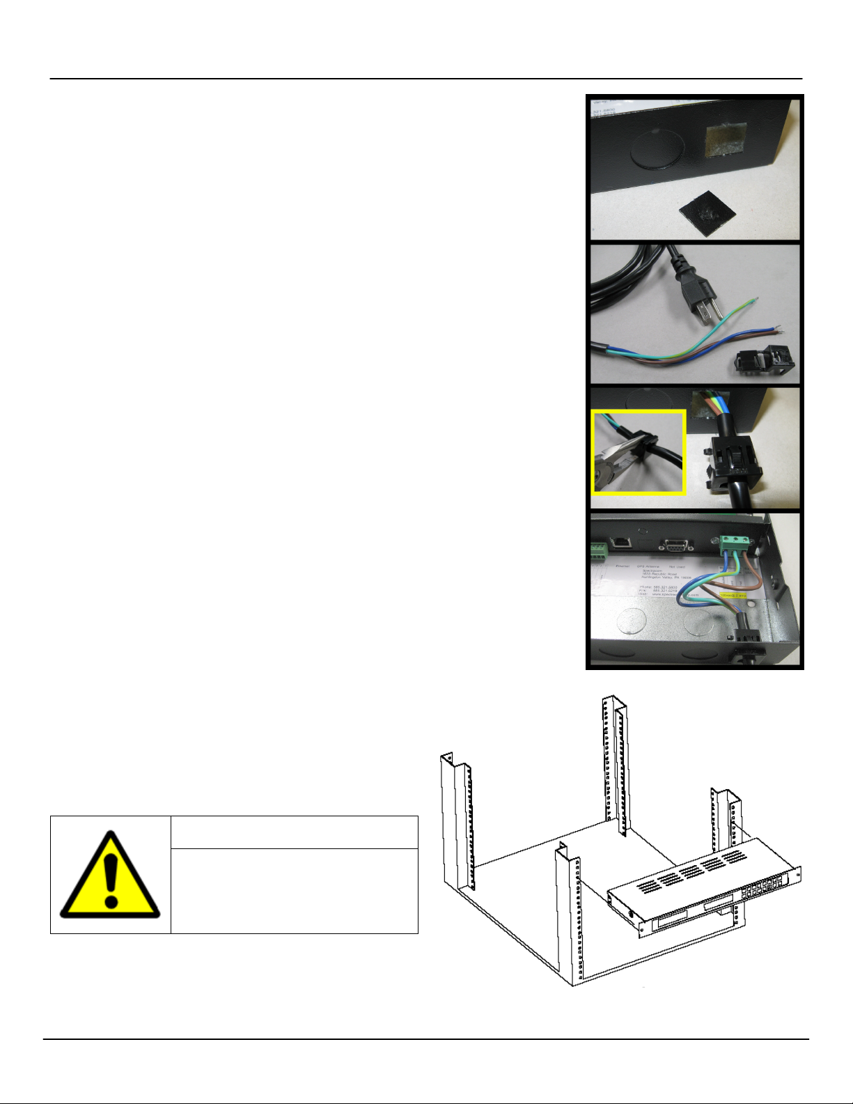
1. Remove the rear
cover of the chassis
and punch out the
square knockout.
2. Strip the power cord
wires and prepare
the plastic bushing
used with the power
cord.
3. Use pliers to install
the bushing, lettering
facing up, roughly
one inch from the
end of the power
cord insulation.
4. Connect the power
wires according to
the wiring diagram
found inside the
transceiver chassis.
The plastic bushing
the outside.
Figure 2-1: Line Cord Receptacle Installation
2.1.1 Connect Transceiver Power
Remove the rear cover. Prepare the power cord (Figure 2-1).
Installation personnel will need to punch out the appropriate access
hole in the transceiver chassis in order to make the connection.
be connected by qualified personnel only.
Installation of the power cord by unqualified
personnel may cause injury or death and
will void the Spectracom product warranty.
2.1.2 Mount the Transceiver
Mount the transceiver in your equipment rack using the Nylon
washers, the screws, and the threaded nuts supplied (Figure 2-2).
You may wish to make connections first. (A wall mount version of the
transceiver is also available. Drill and install as appropriate using the
equipment provided.)
Spectracom Corporation: 1565 Jefferson Road, Rochester, NY 14623 2 of 19
Figure 2-2: Rack-Mounting the Transceiver
Page 3
For Complete Warranty Information, contact Spectracom NetClock Wireless Clock System Instructions
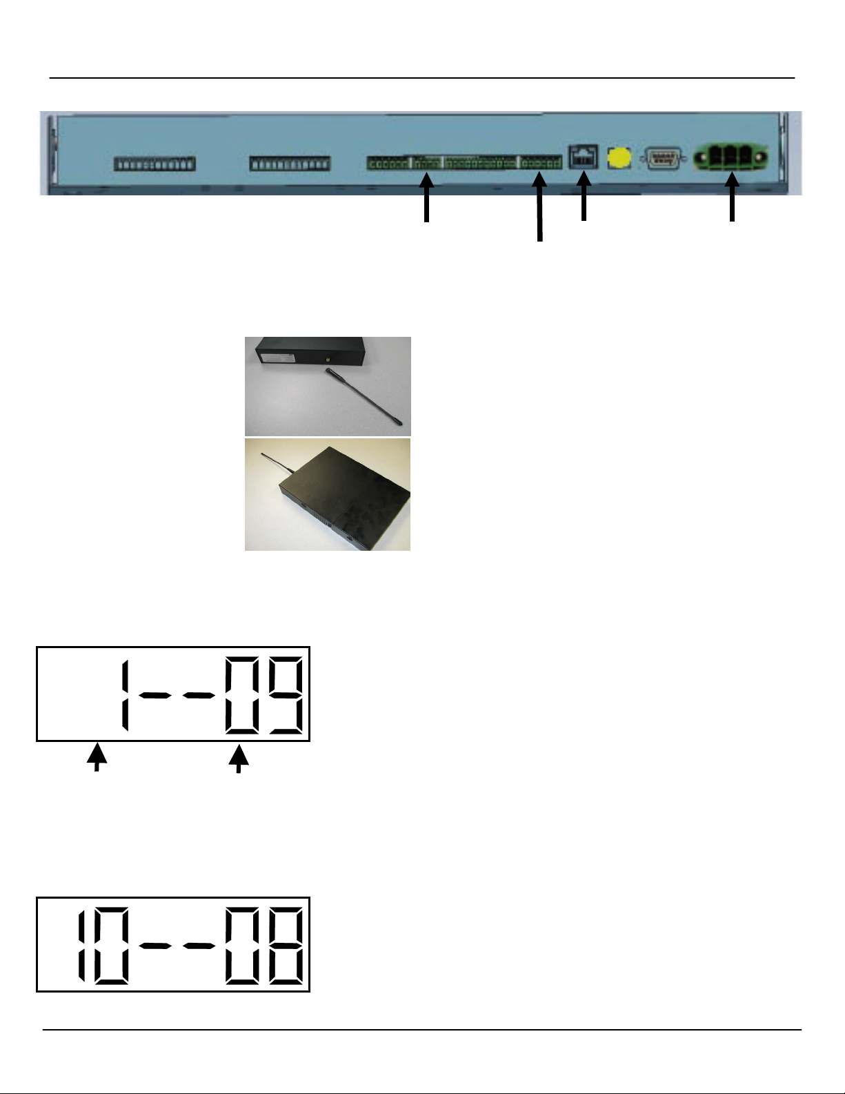
RS-485 ETHERNET POWER
REMOTE RF
OPTION NUMBER
CONFIGURED OPTION
www.spectracomcorp.com / US +1.585.321.5800 1168-5001-0050 Rev. H, Copyright June, 2011
ANTE NN A
Figure 2-3: Transceiver Connections
2.1.3 Make Necessary Connections
1. Make all connections as shown
in Figure 2-3 and according to
the wiring and connection
diagrams found inside the
transceiver chassis. Do not
forget to connect the
transceiver’s remote RF
antenna (right).
This is must be wired from the
transceiver to the repeatersized box provided. The small
whip antenna also provided
must be screwed into place in
the repeater-sized box. Replace
the transceiver cover and apply
power.
2.2 Configuring the Transceiver
After the transceiver is installed, it must be configured. This can be
done at the transceiver using its built-in LED display with the “Set
Hour” and “Set Minute” buttons, or it may be done through your
network using the transceiver’s Web User Interface (Web UI).
NOTE: Configuring the transceiver through the Web UI requires
that the unit be assigned an IP address so it can be
accessed through the network. If your network is not
running DHCP or the transceiver cannot acquire an IP
address when connected, you must assign a static IP
address to the transceiver.
2.2.1 Configuring the Transceiver from the LED Display
There are two buttons located on the transceiver next to the LED
display. These buttons are “Set Hour” and “Set Minute.” To enter
the programming mode, which allows you to configure the
transceiver, press both the “Set Hour” and “Set Minute” buttons
simultaneously.
Once programming mode has been entered, the number "1" will appear in the far left
position. Option 1, for example, sets the year, while options 2 and 3 set the month and
day. (It is not necessary to change the year, month, or day manually if your transceiver
receives an external timing reference from some other source, such as a NetClock.)
Press the top button (the “Set Hour” button) to advance the option until the number
displayed matches the numbers described herein (the left-hand numbers). Press the
bottom button (the “Set Minute” button to change the option as described, configuring your
clocks as required.
NOTE: Do NOT change options that are not listed in these instructions. Changing
options unnecessarily may alter the configuration of your transceiver and affect
Scroll through this
using the top, or
“Set Hour,” button.
Use the bottom or “Set
Minute” button to change
this to the desired option.
its function. Scroll through options not described herein and change only those
options listed (and necessary).
After each option is set as desired, use the top button (the “Set Hour” button) to scroll to
the next option you wish to configure. Again, scroll PAST any items not described herein.
They do not apply to your Spectracom system and should not be changed.
Option 10: Access Options 12 and 13
Use the bottom button (the “Set Minute” button) to change the option to “08” in order to set
options 12 and 13. Entering any other value for Option 10 will cause the menu to scroll to
option 20 when the “Set Hour” button is pressed again. (You do not need to set option 11.)
8: Access Options 12 and 13
Spectracom Corporation: 1565 Jefferson Road, Rochester, NY 14623 3 of 19
Page 4
For Complete Warranty Information, contact Spectracom NetClock Wireless Clock System Instructions
www.spectracomcorp.com / US +1.585.321.5800 1168-5001-0050 Rev. H, Copyright June, 2011
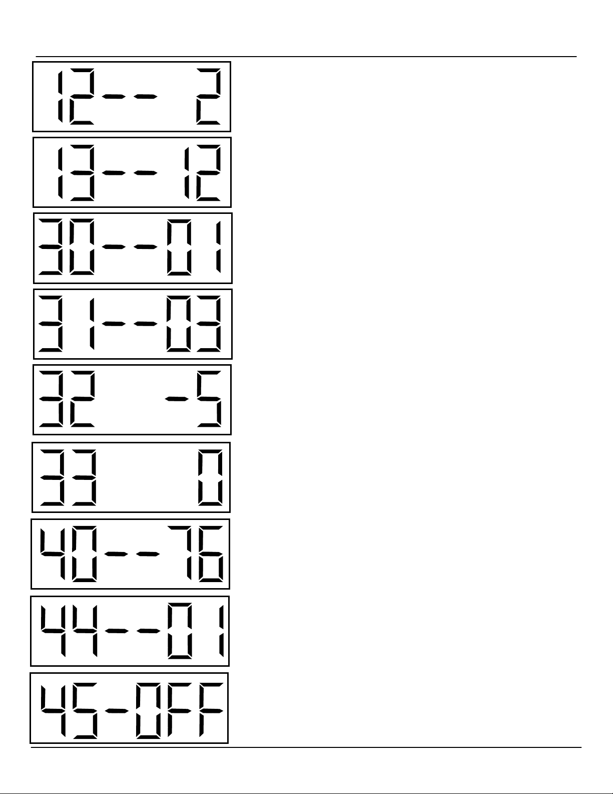
Option 12: Enable or Disable Daylight Saving Time (DST)
Skip option 11 and access option 12. Use the bottom button (the “Set Minute” button) to
change the option to 1, 2, or “d.”
1: Pre-2007 DST Rule
2: Post-2007 DST Rule
d: Disable DST Rule
Option 13: Set 12- or 24-Hour Mode
Use the bottom button (the “Set Minute” button) to change the option to 12 or 24.
12: 12-Hour Display
24: 24-Hour Display
Option 30: Set the Primary Auxiliary Input
Use the bottom button (the “Set Minute” button) to change the option to 01 or 13. Do NOT
use any other available value, for these values may affect the transceiver’s operation.
01: SNTP (your network Ethernet connection)
13: RS-485
Option 31: Set the Secondary Auxiliary Input
Use the bottom button (the “Set Minute” button) to change the option to either 01 or 13. Do
NOT use any other available value, for these values may affect the transceiver’s operation.
01: SNTP (your network Ethernet connection)
13: RS-485
Option 32: Set Time Zone Offset
Use the bottom button (the “Set Minute” button) to change the option to the number of
hours of time zone offset desired. For example, -5 sets the offset to EST. The available
offset values range from -12 to 12.
Option 33: Set Input Time Bias
This option allows the user to set a number of seconds to adjust the input time, ranging
from 0 to 7500 seconds. (In most cases, it is not necessary to set this value.)
Option 40: Status, Last Input Signal Received
This is a read-only value that indicates the number of hours since the unit last received an
input signal. This option cannot be modified.
Option 44: Status, Internet Connectivity
This is a read-only value that indicates whether the unit is connected to the Internet. “01”
indicates that an Internet connection is present. “00” indicates that an Internet connection
is not available. This option cannot be modified.
Option 45: Set the Unit to its Static IP Address
Use the bottom button (the “Set Minute” button) to change the option to “OFF” or “cr.” This
allows the user to set the unit to its default static IP address (when DHCP is not available).
NOTE: When setting the unit to static IP, wait 20 seconds and then CYCLE POWER.
OFF: Obtain IP Address Using DHCP (Normal Network Mode)
cr: Crossover Mode (unit’s IP address fixed to 192.168.0.123)
Spectracom Corporation: 95 Methodist Hill Drive, Rochester, NY 14623 4 of 19
Page 5
For Complete Warranty Information, contact Spectracom NetClock Wireless Clock System Instructions
www.spectracomcorp.com / US +1.585.321.5800 1168-5001-0050 Rev. H, Copyright June, 2011
2.2.2 Configuring the Transceiver from the Web UI
The transceiver may be configured through the Web User Interface
(Web UI). If your network includes DHCP, the transceiver will
acquire an IP address automatically. When the unit is connected to
your network and power is applied, determine the IP address as
follows:
1. Press the “Set Hour” and “Set Minute” buttons
simultaneously and release them. The unit will enter
programming mode.
2. Press the “Set Hour” and “Set Minute” buttons
simultaneously again and release them. The unit will
display “IP 000,” where 000 is the first three digits of the IP
address it has been assigned. Press and release both
buttons simultaneously several times to prompt each of the
segments of the IP address to display. When you have
finished scrolling through the address, the unit should
return to its time display. (If you accidentally enter
programming mode, you can press the “Set Hour” button to
scroll through the menu options until the time display
returns.)
3. Navigate to the displayed IP address in your web browser.
You will be prompted to log in. In the screens provided as
illustrations herein, the IP address assigned to the
transceiver was 192.168.1.41.
2.2.3 If Your Network Does Not Support DHCP
If your network does not support DHCP or your transceiver cannot
acquire an IP address from your network, set the unit to its default
static IP address by performing the following steps:
1. There are two buttons located on the transceiver next to the
LED display. These buttons are “Set Hour” and “Set
Minute.” To enter the programming mode, which allows
you to configure the transceiver at the unit, press both the
“Set Hour” and “Set Minute” buttons simultaneously.
2. Once programming mode has been entered, the number
"1" will appear in the far left position. Option 1, for
example, sets the year, while options 2 and 3 set the month
and day. (It is not necessary to change the year, month, or
day manually if your transceiver receives an external timing
reference from some other source, such as a NetClock.)
3. Press the top button (the “Set Hour” button) to advance the
option until the number displayed is “45.” Press the bottom
button (the “Set Minute” button to change the option on the
right side from “OFF” to “cr.” This means the unit has
entered the crossover mode. It has been set to its factory
default static IP address, 192.168.0.123.
NOTE: Do NOT change any other options when making this
adjustment. Refer to Configuring the Transceiver from the
LED Display for more information.
4. Use the “Set Hour” button to scroll past the remaining menu
options and return to the time display. Cycle the unit power.
NOTE: Power to the unit MUST be cycled once this configuration
change has been made, or the change to static IP address
will not be applied. Wait 20 seconds before cycling
power. It is critical that power be cycled after this delay.
5. Using a web browser on a computer connected to your
transceiver’s network, navigate to 192.168.0.123.
Spectracom Corporation: 1565 Jefferson Road, Rochester, NY 14623 5 of 19
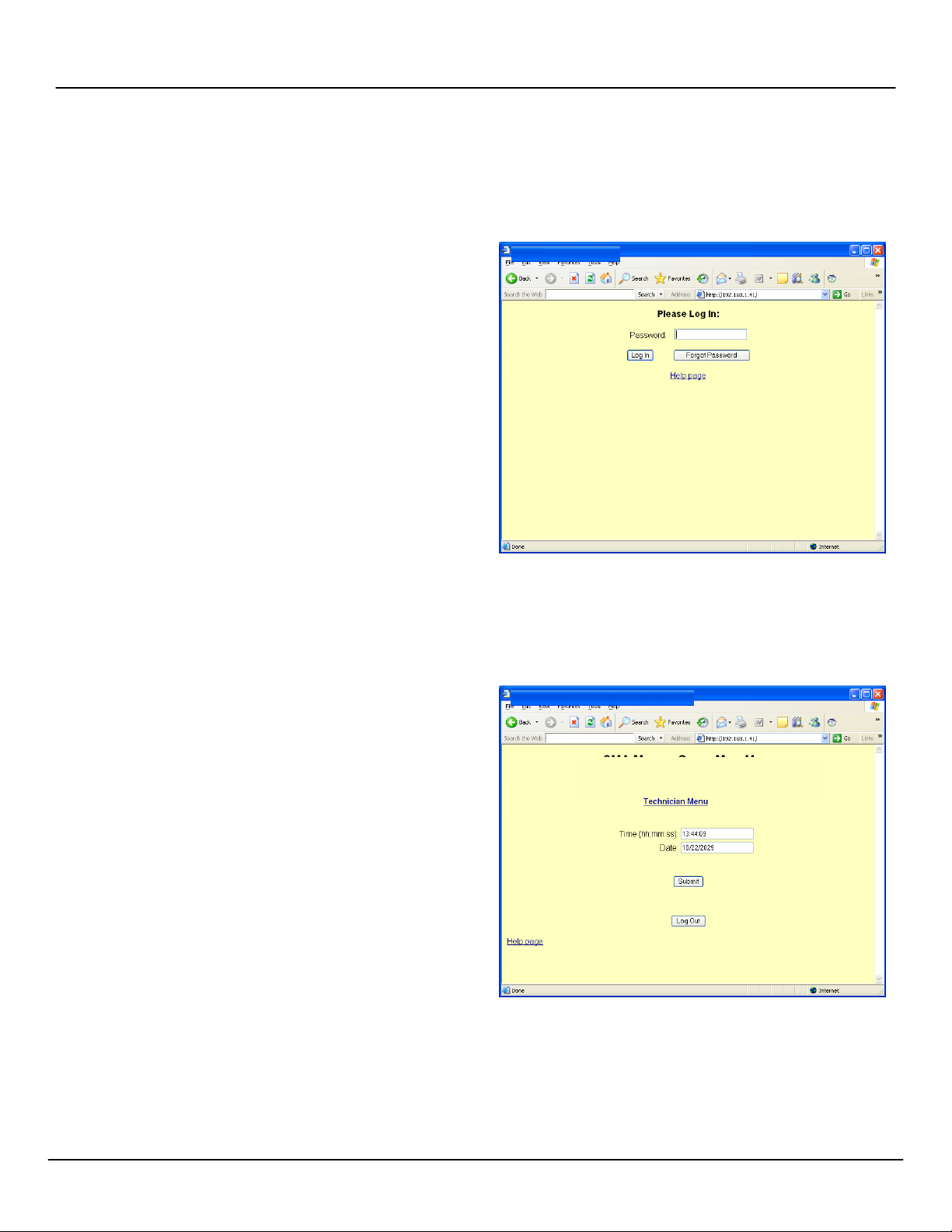
2.2.4 Web UI Configuration
When you navigate to the transceiver’s IP address (either assigned
through DHCP or as set statically using the factory default), you will
be prompted to log in. The factory default password is 6063.
NOTE: Screen captures are shown for illustrative purposes. Your
software may vary slightly from the depictions contained
herein.
Figure 2-4: Login Screen
Once you have logged into the Web UI (Figure 2-5), you may change
the date and time or access the technician-level menu.
NOTE: Remember to click “submit” rather than simply pressing
“enter” when making changes in the Web UI.
Figure 2-5: Successful Login
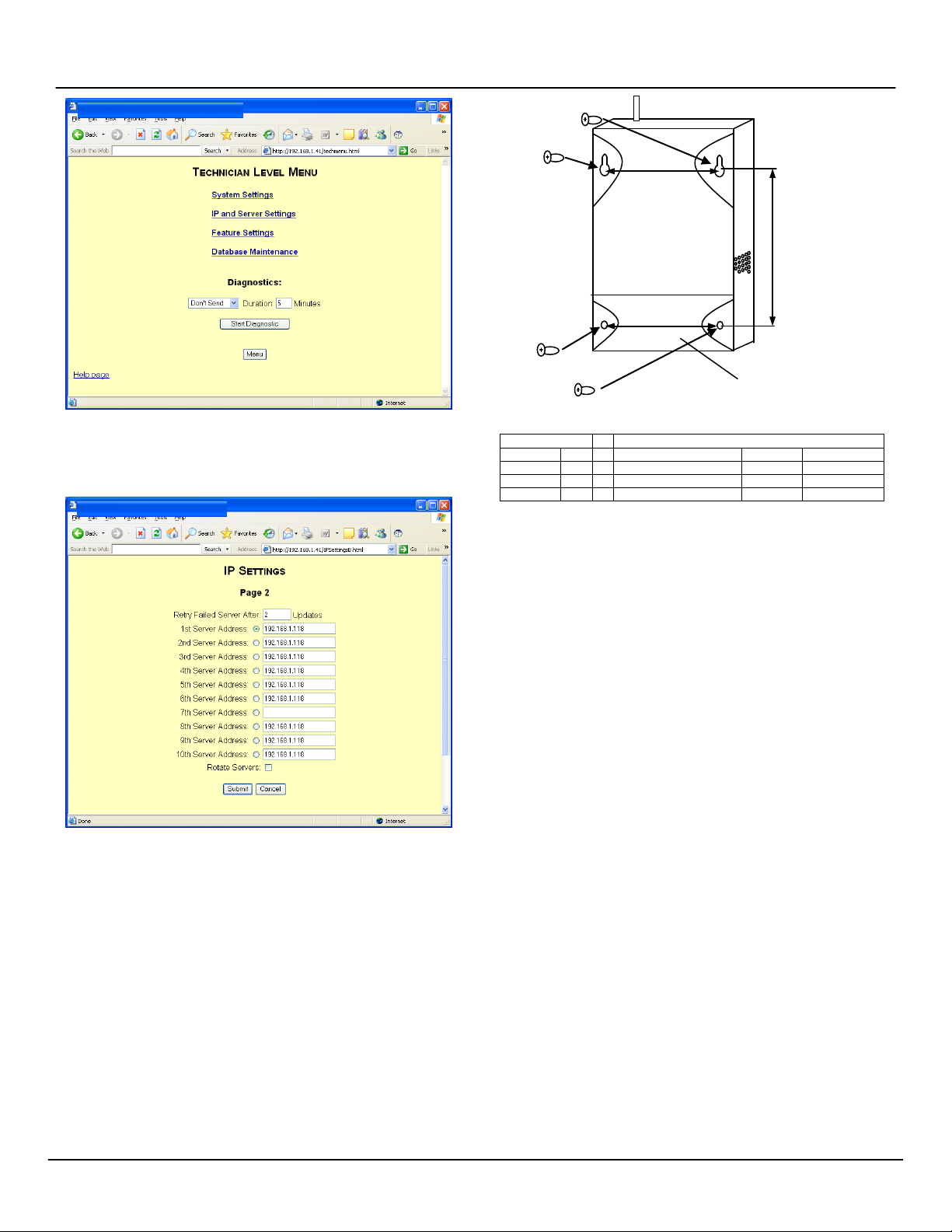
From the technician-level menu (Figure 2-6), the user may change
system settings such as password, RS-485 data rate, time zone
offset, and input references. Web UI pages are reasonably intuitive;
simply follow the directions provided.
Page 6
For Complete Warranty Information, contact Spectracom NetClock Wireless Clock System Instructions
6.938 in.
17.6 cm
5.75 in.
WIRING PANEL
RS-485 120VAC @ 0.2 Amps
Input A
10
USA
Europe
Input B
9 L2 Neutral
White
Blue
Output B
8 Ground
Green
Yellow/Green
Output A
7 L1 Hot
Black
Brown
www.spectracomcorp.com / US +1.585.321.5800 1168-5001-0050 Rev. H, Copyright June, 2011
6.938 in.
17.6 cm
14.6 cm
Figure 2-6: Technician-Level Menu
NOTE: When setting IP addresses (Figures 2-7) it may or may not
be necessary to repeat IP addresses in multiple fields.
Figure 2-8: Repeater Installation
REPEATER WIRING TABLE
2.4 Installing Digital Display Clock(s)
Display clocks can be wall-mounted (Figure 2-9) or double-mounted
(Figure 2-12). Spectracom recommends the following installation
procedure:
1. Wireless Clocks can be powered from a 24 volt source or
from a 110 volt source. For four-digit clocks, connect the
wiring as shown in Figure 2-10, setting the clock board’s
jumpers as required.
Figure 2-7: Populating IP Address Fields
NOTE: There may be many settings accessible through the Web
UI that you need not change for your application.
Whenever you are not certain of a value, leave it set to the
factory default. Contact Spectracom Customer Service at
US +1.585.321.5800 if you require further assistance.
2.3
Installing Antennas and Repeaters
Antennas and repeaters are built using identical housings. Install
repeaters to cover gaps in signal coverage. Remove the cover of the
chassis, install physically as shown in Figure 2-8, and wire as shown
in the repeater wiring table. Set repeater jumpers JP1 and JP2 on
the bottom pair of each trio of pins. (The top pair of pins on the
jumpers are used when the unit is used as a transmitter.)
NOTE: 14 AWG is the smallest conductor acceptable for power
input.
NOTE: For six-digit clocks, connect the wiring as shown in
NOTE: For 24 volt installations, make sure the transformer is
NOTE: Wall-mounted clocks may also be mounted flush with the
To double-mount digital display clocks (Figure 2-12), Spectracom
recommends the following procedure:
Figure 2-11 and refer to Section 3 for clock configuration
and programming. Figure 3-1 includes detailed wiring.
2. Mount the wall mount box into the double gang box using
four machine screws.
3. Connect the ground wire into the flush mount box using a
tooth lockwasher and machine screw nut.
4. Disconnect the red filter from the display panel.
5. Complete the wiring connections as shown herein.
ISOLATED.
6. Mount the display panel into the flush mount box using four
black machine screws. Make sure the switches are on the
right side.
7. Snap the red filter into the display panel.
wall surface.
1. Screw the hanger/mounting rod into the crossbar.
2. Insert the wires through hanger/mounting rod.
Spectracom Corporation: 1565 Jefferson Road, Rochester, NY 14623 6 of 19
Page 7

For Complete Warranty Information, contact Spectracom NetClock Wireless Clock System Instructions
www.spectracomcorp.com / US +1.585.321.5800 1168-5001-0050 Rev. H, Copyright June, 2011
Figure 2-9: Mounting Digital Display Clocks
Refer to the following section for information regarding digital display clock wiring (4 and 6 digit units).
Spectracom Corporation: 1565 Jefferson Road, Rochester, NY 14623 4 of 19
Page 8

For Complete Warranty Information, contact Spectracom NetClock Wireless Clock System Instructions
J
1
J
2
J
JP1
JP2
JP3
12/24 Hour Mode
Brightness
Loss of
ON: 12 hour mode
ON: Brightest
ON: 5 minutes
24 Volts
Ground
110 Volts
ON
NOTE: North American standard colors black,
neutral (respectively) correspond to
www.spectracomcorp.com / US +1.585.321.5800 1168-5001-0050 Rev. H, Copyright June, 2011
110 Volts
BOX
P
P
P
3
Comm. Alert
OFF: 24 hour
mode
Figure 2-10: Digital Display Clock Wiring (4-Digit Typical)
OFF: Less Bright
OFF: 30 minutes
green, and white for power, ground, and
brown, green/yellow, and blue internationally.
Figure 2-11: Digital Display Clock Wiring (6-Digit Units)
Refer to the following section for an illustration of double-mounting digital displays.
Spectracom Corporation: 1565 Jefferson Road, Rochester, NY 14623 4 of 19
Page 9

For Complete Warranty Information, contact Spectracom NetClock Wireless Clock System Instructions
www.spectracomcorp.com / US +1.585.321.5800 1168-5001-0050 Rev. H, Copyright June, 2011
Figure 2-12: Double-mounting Digital Display Clocks
Spectracom Corporation: 1565 Jefferson Road, Rochester, NY 14623 5 of 19
Page 10

For Complete Warranty Information, contact Spectracom NetClock Wireless Clock System Instructions
12" DISPLAY CLOCK 16" DISPLAY CLOCK
www.spectracomcorp.com / US +1.585.321.5800 1168-5001-0050 Rev. H, Copyright June, 2011
3. Install the crossbar into the double gang box using two
screws.
4. Mount the double mount box into the clock base using two
nuts and a tooth lockwasher. The double mount can be
mounted on a wall or ceiling.
5. Insert the two 0.187” locking hole plugs and the
0.562”locking hole plug into the unused holes.
6. Insert the double mount case onto the hanger/mounting
rod.
7. Insert the support bracket onto the hanger/mounting rod.
8. Screw the two nuts onto the hanger/mounting rod and
secure the clock base to the wall.
9. Connect the ground wire into the double mount box using a
tooth lockwasher and machine screw nut.
10. Disconnect the red filter from the display panel.
11. Complete the wiring connections as detailed herein.
NOTE: For 24 volt installations, make sure the transformer is
ISOLATED.
12. Mount the display panel on one side of the double mount
box using four black machine screws. Make sure the
switches are on the right side.
13. Snap the red filter into the display panel.
14. Repeat steps 9-13 for the second clock.
2.4.1 Synchronizing to the Transceiver
1. Place transceiver in a central location (hallway
recommended).
2. Pick the location of the digital display clock(s).
3. Place each display clock in a location where the
signal is available from the transceiver. In order to
verify that the clock is receiving a signal from the
transceiver, power up the clock. The display clock
should indicate the transceiver’s transmitted time
within a few minutes of power-up and will search for
a signal for 30 minutes after initial startup. If the
clock does not correct to the transceiver time,
choose a different location for the clock.
4. Repeat steps 2 and 3 for each display clock.
Remember as you test each clock that display
clocks can receive and repeat signals from and to
each other, not just from the transceiver unit.
NOTE: Before installing display clocks, remove the pin used to
immobilize the clock hands for shipping. The pin is clearly
designated with the label, “Remove Pin Before Installation.”
1. Wireless Clocks can be powered using two D-cell batteries,
from a 24 VAC source, or from a 110 VAC source. Install
the batteries before mounting the display clock(s). If you
are directly wiring power to the display clock(s), connect the
wiring as shown in Figure 2-14.
2. Mount both plastic anchors in the wall.
3. Insert the sheet metal screws (#10) through the mounting
bracket into the plastic anchors.
4. Plug the connector into the movement (220V, 110V, and
24V installations only).
5. Hang the clock on the mounting bracket.
6. Install the screw (4mm) through the hole on the top of the
clock into the hole at the top of the mounting bracket.
Figure 2-13: Mounting Analog Display Clocks
Refer to the next section for information regarding
Analog Display Clock wiring, LEDs, and switches.
2.5 Installing Analog Display Clock(s)
Display clocks can be wall-mounted or double-mounted. For simple
wall mounting, refer to Figure 2-13. Spectracom recommends the
following installation procedure:
Spectracom Corporation: 1565 Jefferson Road, Rochester, NY 14623 4 of 19
Page 11

For Complete Warranty Information, contact Spectracom NetClock Wireless Clock System Instructions
Diagnostic LED
Switch 2
FCC ID
NOTE: North American standard colors black,
neutral (respectively) correspond to
220V W
www.spectracomcorp.com / US +1.585.321.5800 1168-5001-0050 Rev. H, Copyright June, 2011
DIAGNOSTIC
Switch 1
TRANSMIT/RECEIVE
green, and white for power, ground, and
brown, green/yellow, and blue internationally.
VARIATION
IRING
Refer to the next section for information regarding double-mount installation of display clocks.
Spectracom Corporation: 1565 Jefferson Road, Rochester, NY 14623 4 of 19
Figure 2-14: Analog Display Clock Wiring, LEDs, and Switches
Page 12

For Complete Warranty Information, contact Spectracom NetClock Wireless Clock System Instructions
Figure 2-15: Double-mounting Analog Display Clocks
www.spectracomcorp.com / US +1.585.321.5800 1168-5001-0050 Rev. H, Copyright June, 2011
To double-mount display clocks (Figure 2-15), Spectracom recommends the following procedure:
1. Wireless Clocks can be powered using two D-cell batteries, from a 24 VAC source, from a 110 VAC source, or from a 220
2. Screw the mounting bracket to the double gang box using the four inner holes on the mounting bracket, or mount the
3. Insert the wires through the mounting bracket (220V, 110V, and 24V installations only)
4. Fish the wires through the clock hanging rod.
5. Secure the hanging rod to the mounting bracket with the appropriate screws. Place the cover over the connection.
6. Connect the wiring as shown in Figure 2-14 (220V, 110V, and 24V installations only).
7. Plug the connectors into the movements (220V, 110V, and 24V installations only).
8. Place the clocks on the double mount housing and tighten the screws to secure the clocks as shown above.
VAC source. Install the batteries before mounting the display clock(s).
mounting bracket directly to the wall or ceiling using the four outer holes.
Spectracom Corporation: 1565 Jefferson Road, Rochester, NY 14623 4 of 19
Page 13

For Complete Warranty Information, contact Spectracom NetClock Wireless Clock System Instructions
www.spectracomcorp.com / US +1.585.321.5800 1168-5001-0050 Rev. H, Copyright June, 2011
2.5.1 Synchronizing to the Transceiver
1. Install the transceiver.
2. Pick the location of the display clock(s).
3. Place each display clock in a location where the signal is
available from the transceiver. In order to verify that the
clock is receiving a signal from the transceiver, power up
the clock. (This can be done simply by removing the
clock’s battery cover, installing two D-cell batteries, and
replacing the battery cover.) The display clock should
indicate the transceiver’s transmitted time within five
minutes of power-up. If the clock does not correct to the
transceiver time, choose a different location for the clock.
4. Repeat steps 2 and 3 for each display clock. Remember as
you test each clock that display clocks can receive and
repeat signals from and to each other, not just from the
transceiver unit.
NOTE: The transceiver transmits once per minute. Battery-
powered wireless analog clocks transmit once every two
hours in normal mode and once every four hours in
economy mode. Refer to Conserving Battery Power to
toggle economy mode.
Go to the unsynchronized clock and press Switch #2. The second
hand should move to 20 seconds until the unsynchronized clock
receives the signal from transmitting, synchronized clock. The
previously unsynchronized clock should correct for the synchronized
time within five minutes. Within ten minutes, the first clock (the clock
used to transmit time) should resume normal operation.
Continue this troubleshooting process with all clocks that failed to
correct for the transceiver’s transmitted time. Remember that while
one clock is transmitting, you may synchronize multiple display
clocks within range of receiving the transmitted signal. Each clock
you synchronize as you move farther away from the transceiver
extends the range at which you can synchronize more clocks.
2.5.2 Conserving Battery Power
To toggle economy mode, press Switch #1 and Switch #2 (on the
back of the clock) simultaneously. When in economy mode, the
diagnostic LED will illuminate solid green for one minute and the
second hand will move to numeral 8. When in normal mode, the
diagnostic will illuminate solid red for one minute and the second
hand will move to numeral 5.
2.5.3 Manually Transmitting and Receiving
To synchronize display clocks after initial installation, you may wish
to send or receive time signals manually:
Pressing Switch #2 twice in rapid succession will enable the receiver
manually for ten minutes, allowing the clock to receive the time
signal. The second hand will move to the 20 second location until
the signal is received. The clock will then resume normal operation.
Pressing Switch #2 once will enable the clock transceiver for ten
minutes, allowing the clock to transmit the time signal. The clock
transceiver can be enabled only if the clock has received a time
signal within the last 12 hours. In this case, the second hand will
move to the 40 second location. The clock will resume normal
operation after ten minutes.
2.5.4 Testing the Distance Between Clocks Used as Repeaters
If display clocks distributed through a facility or across a campus are
too far apart, they may fail to transmit/repeat time to each other. If
during installation all clocks do not correct for the transceiver’s time,
find the corrected, synchronized clock closest to the first
unsynchronized clock. Press Switch #2 on the synchronized clock.
The second hand should move to 40 seconds and the clock should
stop running. This indicates that the synchronized clock is now in
transmission mode.
Spectracom Corporation: 1565 Jefferson Road, Rochester, NY 14623 4 of 19
Page 14

For Complete Warranty Information, contact Spectracom NetClock Wireless Clock System Instructions
Figure 3-1: Detailed Wiring for 6-Digit Digital Clocks
www.spectracomcorp.com / US +1.585.321.5800 1168-5001-0050 Rev. H, Copyright June, 2011
3 Configuring 6-Digit Digital Clocks
Spectracom Wireless Clock Systems incorporating six-digit display clocks offer certain features not found on four-digit display clocks.
Configuration of these clocks therefore differs from four-digit models.
Unlike four-digit display clocks, six-digit display clocks do not have jumpers. All feature programming and configuration is performed at the
clock. If your six-digit display clocks will be used with other systems and infrastructure, refer to the detailed wiring specifications in Figure 3-1.
NOTE: These wiring details include specifications for the Digital Timer System control box. For more information, refer to the Digital Timer
3.1 Configuring Six-Digit Clocks Individually
After your six digit clocks are installed, configure their display options at the individual clocks themselves. There are two buttons on the right
side of the clock that are used for this purpose. (The top button, pressed by itself, sets the hours, while the bottom button, pressed by itself,
sets the minutes. You will not need to set the clock time because your wireless system governs this.)
Press both buttons together to put the clock in programming mode. Press the top button to advance the option and press the bottom button to
change the option. To exit programming mode, continue to press the top button until the time is displayed (after option 40).
NOTE: When the LED in the top left corner of the unit is illuminated, the time is displayed in PM hours.
System Instructions, which are provided with your Digital Timer System.
CONTROL
Spectracom Corporation: 1565 Jefferson Road, Rochester, NY 14623 4 of 19
Page 15

For Complete Warranty Information, contact Spectracom NetClock Wireless Clock System Instructions
OPTION NUMBER
CONFIGURED OPTION
www.spectracomcorp.com / US +1.585.321.5800 1168-5001-0050 Rev. H, Copyright June, 2011
Once programming mode has been entered, the number "1" will appear in the far left
position. Option 1, for example, sets the year, while options 2 and 3 set the month and
day. It is not necessary to change the year, month, or day manually because system time
is driven by the wireless clock system.
Press the top button (the “Set Hour” button) to advance the option until the number
displayed matches the numbers described herein (the left-hand numbers). Press the
bottom button (the “Set Minute” button to change the option as described, configuring your
clocks as required.
NOTE: Do NOT change options that are not listed in these instructions. Changing
Scroll through this
using the top, or
“Set Hour,” button.
Use the bottom or “Set
Minute” button to change
this to the desired option.
options unnecessarily may alter the configuration of your clock. Scroll through
options not described herein and change only those options listed (and
necessary).
After each option is set as desired, use the top button (the “Set Hour” button) to scroll to
the next option you wish to configure.
Option 4: Set 12 or 24-Hour Mode
Use the bottom button (the “Set Minute” button) to change the option from 12 to 24 as
desired for your time display.
Option 5: Set Daylight Saving Time
Use the bottom button (the “Set Minute” button) to change the option to 1, 2, or “d.”
1: Pre-2007 DST Rule
2: Post-2007 DST Rule
d: Disable DST Rule
Option 6: Set Alternating Time/Date Display
Use the bottom button (the “Set Minute” button) to change the option to “E” or “d.”
E: Enable alternating time display (switches from time to date and back automatically)
d: Disable alternating time display
Option 8: Set Brightness
Use the bottom button (the “Set Minute” button) to change the option to 0 or 1.
0: Normal Brightness
1: Brightest Setting
Option 13: Activate or Deactivate Loss of Communication Alert
Use the bottom button (the “Set Minute” button) to change the option to “E” or “d”.
E: Enables the option, allowing the user to scroll to Option 14 to set the alert.
d: Disables the option. Use this option when the clock is used independently.
Spectracom Corporation: 1565 Jefferson Road, Rochester, NY 14623 5 of 19
Page 16

For Complete Warranty Information, contact Spectracom NetClock Wireless Clock System Instructions
www.spectracomcorp.com / US +1.585.321.5800 1168-5001-0050 Rev. H, Copyright June, 2011
4 Troubleshooting
Spectracom NetClock Wireless Clocks are not field-serviceable and
must be returned to the factory for repair. Users may, however,
troubleshoot the system using the following guidelines.
4.1 Transceiver Troubleshooting Tips
If the following troubleshooting tips do not cover your installation
issue, contact Spectracom Customer Support at US
+1.585.321.5800.
NOTE: For RS-485 connections, time zone offset and DST rules
are configured in the NetClock unit and NOT configured in
the transceiver if you are using a NetClock as an external
timing reference. The NetClock remote output (RS-485)
must be set to Format 0, 1200 baud only. Refer to the
NetClock manual for more information.
4.1.1 Transceiver Will Not Synchronize to External Timing Reference
Check the connection from the reference to the transceiver. Refer to
the NetClock instrtuction manual for more information. If necessary,
contact Spectracom Customer Support at US +1.585.321.5800.
4.1.2 Transceiver Does Not Power Up
Make sure the power cord is securely and properly connected. There
is no power switch as such. Power is applied when the unit is
plugged in.
4.2 Clock Troubleshooting Tips
If the following troubleshooting tips do not cover your installation
issue, contact Spectracom Customer Support at US
+1.585.321.5800.
Option 14: Set the Loss of Communication Alert
This option allows the user to set the delay after which the clock’s digital colon will flash to
indicate a loss of communication from the transceiver. Use the bottom button (the “Set
Minute” button) to change the option from among the ten possible choices.
1: 5 minutes 4: 30 minutes 7: 90 minutes 10: 240 minutes
2: 10 minutes 5: 45 minutes 8: 120 minutes
3: 15 minutes 6: 60 minutes 9: 180 minutes
Option 20: Disable the Programmable Relay
Option 20 must be set to “d” to disable the programmable relay, which does not apply to
your product. Use the bottom button (the “Set Minute” button) to select “d” from among the
available numerical options. Do not choose settings1 through 9.
Option 30: Disable Auxiliary Input Control
Option 30 must be set to “d” to disable the programmable relay, which does not apply to
your product. Use the bottom button (the “Set Minute” button) to select “d” from among the
available options. Do not choose “E”.
4.2.1 Digital Clock Does Not Receive Signal (Colon Blinking)
Take the clock within close proximity to the transceiver and power up
the clock. If the clock still does not synchronize, call Spectracom
Customer Support at US +1.585.321.5800.
4.2.2 Digital Clock Does Not Power Up
Make sure the wiring is correct. If the clock is 24 volt, the power
should be on the orange and yellow wires of the harness. If the clock
is 110 volt, the power should be on the black and white wires. The
middle wire is ground. If the wiring is correct, take a voltmeter and
measure the voltage. For 24 volt models, the voltage should be
between 14 - 28 volts. For 110 volt models, the voltage should read
85 - 135 volts.
4.2.3 Analog Clock Hands Do Not Move After Power-Up
The clock should move at normal speed upon power up. If it does not
move at normal speed, check the battery and make sure the clock
receives power. Also, be sure to remove the pin prior to starting up
the clock. If the clocks are 24 volt or 110 volt, verify the wiring.
4.2.4 Analog Clock Does Not Receive Signal
Take the clock within close proximity to the transceiver and power up
the clock. If the clock is battery operated, remove the battery and put
the battery back in again.
Press Switch #2 on the clock closest to the clock that isn’t working.
The second hand will go to 8, notifying the user that the clock is
transmitting the signal. Go to the clock that isn’t working and press
Switch #2. The second hand will go to 4, notifying the user that it is
searching for the signal. If the clock still does not correct, call
Spectracom Customer Support at US +1.585.321.5800.
Spectracom Corporation: 1565 Jefferson Road, Rochester, NY 14623 6 of 19
Page 17

For Complete Warranty Information, contact Spectracom NetClock Wireless Clock System Instructions
Second
Position
Red
Flashes
hands are striking each other. Repeat the test.
Problem with the hour and/or minute hands. Check
the test.
Call Spectracom Customer Service at US
+1.585.321.5800
www.spectracomcorp.com / US +1.585.321.5800 1168-5001-0050 Rev. H, Copyright June, 2011
4.2.5 Analog Clock Displays Incorrect Time
Perform Diagnostic #1 in order to find the last time that the clock
received the time signal. Perform Diagnostic #3 to check the gears
for the clock.
4.2.6 Desire to Verify Analog Clock Signal Quality
Perform Diagnostic #2.
4.2.7 Signal to Desired Clock Location Receives is Marginal
Reposition the transceiver or install a clock to act as a repeater.
4.2.8 Distance Between Clocks is Too Great
Install a repeater to provide additional range between clocks.
4.3 Analog Diagnostic 1
In order to enter the diagnostic mode, press Switch #1 (Figure 2-14).
The number of times the switch is pressed determines which
diagnostic is applied. The LED between the two switches will start
flashing green. The number of flashes corresponds to the diagnostic
number.
Diagnostic 1 determines how long (in number of hours) it has been
since the clock last received the communication signal. In order to
enter Diagnostic 1, press and release Switch #1 only once. The LED
should indicate green and flash once every three seconds.
1. While in diagnostic modes, the clock’s hour and minute
hands will continue to run normally.
2. The second hand will display how long it has been since
the clock received a time signal (Table 4-1).
3. After three minutes, the clock will resume normal operation.
Hand
12 Within the past hour
1 Between one and two hours ago
2 Between two and three hours ago
3 Between three and four hours ago
4 Between four and five hours ago
5 Between five and six hours ago
6 Between six and seven hours ago
7 Between seven and eight hours ago
8 Between eight and nine hours ago
Time Since Clock Last
Received Communication Signal
4.4 Analog Diagnostic 2
In order to enter the diagnostic mode, press Switch #1 (Figure 2-14).
The number of times the switch is pressed determines which
diagnostic is applied. The LED between the two switches will start
flashing green. The number of flashes corresponds to the diagnostic
number.
Diagnostic 2 determines the quality of the time signal. In order to
enter Diagnostic 2, press and release Switch #1 twice. The LED
should indicate green and flash twice every three seconds.
1. While in diagnostic modes, the clock’s hour and minute
hands will continue to run normally.
2. The second hand will display the quality of the time signal
as a percentage on the dial of the clock. It will move from 1
to 10, with 1 being the best signal and 10 being the
weakest signal.
3. After three minutes, the clock will resume normal operation.
4.5 Analog Diagnostic 3
In order to enter the diagnostic mode, press Switch #1 (Figure 2-11).
The number of times the switch is pressed determines which
diagnostic is applied. The LED between the two switches will start
flashing green. The number of flashes corresponds to the diagnostic
number.
Diagnostic 3 tests the mechanical portion and some of the electronic
components of the clock. In order to enter Diagnostic 3, press and
release Switch #1 three times. The LED should indicate green and
flash three times every three seconds.
If an error occurs, the clock will flash the red LED to signal the error
code number (Table 4-2). While in Diagnostic 3, the clock will
perform the following steps:
1. Clock moves second hand to numeral 12.
2. Clock moves second hand again to numeral 12, to verify
that the hands arrived after 60 pulses.
3. Clock moves minute and hour hands to the next known
position.
4. Clock moves minute and hour hands again to the same
known position in order to verify that the hands reach the
position after 720 pulses.
5. Clock moves the hour and minute hands to numeral 12.
Diagnosis of Error Code
1, 2
3, 4, 5
Problem with the second hand. Check to see if the
to see if the hands are striking each other. Repeat
9 Between nine and ten hours ago
10 Between ten and eleven hours ago
11 More than eleven hours ago
Table 4-1: Second Hand Positions and Time Indications
Spectracom Corporation: 1565 Jefferson Road, Rochester, NY 14623 7 of 19
6
Table 4-2: Error Codes
Page 18

For Complete Warranty Information, contact Spectracom NetClock Wireless Clock System Instructions
Document Revision History
Rev
ECN
Description
Date
A
2023
First draft of Spectracom instructions.
B 2129
Reformat, add reference to power cord installation.
C 2234
Added alternate digital board wiring diagram, analog 200V variant wiring.
about lower-power transceiver option.
E
2381
Added section for 6-digit clock wiring and programming.
F
2398
Revised manual for new transceiver; added repeater info. Revised analog clock
diagnostics; added economy mode info.
G 2425
Revised power cord installation procedure; added information concerning rackmount antenna.
H
2670
Updated images for mounting / double-mounting Digital and Analog display
minor typographical corrections and maintenance.
June 2011
www.spectracomcorp.com / US +1.585.321.5800 1168-5001-0050 Rev. H, Copyright June, 2011
D 2380
Removed material applicable to Digital Timer System and added information
clocks. Updated caution & warning notes to use new standard table. Additional
Spectracom Corporation: 1565 Jefferson Road, Rochester, NY 14623 8 of 19
Page 19

Spectracom Corporation
1565 Jefferson Road
Rochester, NY 14623
www.spectracomcorp.com
Phone: US +1.585.321.5800
Fax: US +1.585.321.5219
9 of 19
 Loading...