

Page 1

EPSILON
CLOCK
MODEL
EC1S
USER’S MANUAL
95 Methodist Hill Drive
Rochester, NY 14623
Phone: US +1.585.321.5800
Fax: US +1.585.321.5219
3 Avenue du Canada
91974 Les Ulis, France
Phone: +33(0)1.64.53.39.80
Fax: +33(0)1.64.53.39.81
www.spectracomcorp.com
www.spectracom.fr
Ref. Number 14002-D0
Manual Revision D0
09 June 2008
Page 2

Copyright © 2008 Spectracom Corporation. The contents of this publication may not be
reproduced in any form without the written permission of Spectracom Corporation.
Specifications subject to change or improvement without notice.
Spectracom, EPSILON CLOCK, NetClock, Ageless, TimeGuard, TimeBurst, TimeTap,
LineTap, MultiTap, VersaTap, and Legally Traceable Time are Spectracom registered
trademarks. All other products are identified by trademarks of their respective
companies or organizations. All rights reserved.
Page 3

SPECTRACOM LIMITED WARRANTY
LIMITED WARRANTY
Spectracom warrants each new product manufactured and
sold by it to be free from defects in software, material,
workmanship, and construction, except for batteries, fuses, or
other material normally consumed in operation that may be
contained therein AND AS NOTED BELOW, for five years after
shipment to the original purchaser (which period is referred to
as the “warranty period”). This warranty shall not apply if the
product is used contrary to the instructions in its manual or is
otherwise subjected to misuse, abnormal operations, accident,
lightning or transient surge, repairs or modifications not
performed by Spectracom.
The GPS receiver is warranted for one year from date of
shipment and subject to the exceptions listed above. The
power adapter, if supplied, is warranted for one year from date
of shipment and subject to the exceptions listed above.
THE TIMEVIEW ANALOG CLOCKS ARE WARRANTED FOR
ONE YEAR FROM DATE OF SHIPMENT AND SUBJECT TO
THE EXCEPTIONS LISTED ABOVE.
THE TIMECODE READER/GENERATORS ARE
WARRANTED FOR ONE YEAR FROM DATE OF SHIPMENT
AND SUBJECT TO THE EXCEPTIONS LISTED ABOVE.
THE WIRELESS CLOCK SYSTEM TRANSMITTERS AND/OR
TRANSCEIVERS AND CLOCKS ARE WARRANTED FOR
TWO YEARS FROM DATE OF SHIPMENT AND SUBJECT
TO THE EXCEPTIONS LISTED ABOVE.
THE EPSILON CLOCKS, BOARDS, AND
SYNCHRONIZATION UNITS ARE WARRANTED FOR TWO
YEARS FROM DATE OF SHIPMENT AND SUBJECT TO THE
EXCEPTIONS LISTED ABOVE.
The Rubidium oscillator, if supplied, is warranted for two years
from date of shipment and subject to the exceptions listed
above.
All other items and pieces of equipment not specified above,
including the antenna unit, antenna surge suppressor and
antenna pre-amplifier are warranted for 5 years, subject to the
exceptions listed above.
WARRANTY CLAIMS
Spectracom’s obligation under this warranty is limited to infactory service and repair, at Spectracom’s option, of the
product or the component thereof, which is found to be
defective. If in Spectracom’s judgment the defective condition
in a Spectracom product is for a cause listed above for which
Spectracom is not responsible, Spectracom will make the
repairs or replacement of components and charge its then
current price, which buyer agrees to pay.
Spectracom shall not have any warranty obligations if the
procedure for warranty claims is not followed. Users must
notify Spectracom of the claim with full information as to the
claimed defect. Spectracom products shall not be returned
unless a return authorization number is issued by Spectracom.
Spectracom products must be returned with the description of
the claimed defect and identification of the individual to be
contacted if additional information is needed. Spectracom
products must be returned properly packed with transportation
charges prepaid.
Shipping expense: Expenses incurred for shipping
Spectracom products to and from Spectracom (including
international customs fees) shall be paid for by the customer,
with the following exception. For customers located within the
United States, any product repaired by Spectracom under a
“warranty repair” will be shipped back to the customer at
Spectracom’s expense unless special/faster delivery is
requested by customer.
Spectracom highly recommends that prior to returning
equipment for service work, our technical support department
be contacted to provide trouble shooting assistance while the
equipment is still installed. If equipment is returned without first
contacting the support department and “no problems are
found” during the repair work, an evaluation fee may be
charged.
EXCEPT FOR THE LIMITED WARRANTY STATED ABOVE,
SPECTRACOM DISCLAIMS ALL WARRANTIES OF ANY
KIND WITH REGARD TO SPECTRACOM PRODUCTS OR
OTHER MATERIALS PROVIDED BY SPECTRACOM,
INCLUDING WITHOUT LIMITATION ANY IMPLIED
WARRANTY OR MERCHANTABILITY OR FITNESS FOR A
PARTICULAR PURPOSE.
Spectracom shall have no liability or responsibility to the
original customer or any other party with respect to any liability,
loss, or damage caused directly or indirectly by any
Spectracom product, material, or software sold or provided by
Spectracom, replacement parts or units, or services provided,
including but not limited to any interruption of service, excess
charges resulting from malfunctions of hardware or software,
loss of business or anticipatory profits resulting from the use or
operation of the Spectracom product or software, whatsoever
or howsoever caused. In no event shall Spectracom be liable
for any direct, indirect, special or consequential damages
whether the claims are grounded in contract, tort (including
negligence), or strict liability.
EXTENDED WARRANTY COVERAGE
Extended warranties can be purchased for additional periods
beyond the standard five-year warranty for those products
covered under five-year warranty. Contact Spectracom no later
than the last year of the standard five-year warranty for
extended coverage.
www.spectracomcorp.com
www.spectracom.fr
Page 4

Page 5

Spectracom Corporation EPSILON CLOCK MODEL EC1S
EPSILON CLOCK User’s Manual iii
Table of
Table ofTable of
Table of Contents
Contents Contents
Contents
1 INTRODUCTION.............................................................................................................1-1
1.1 Basic Configuration 1-2
1.2 Standard Features 1-2
1.3 Optional Functions 1-2
1.4 Oscillators 1-3
1.5 Inventory 1-3
1.6 Inspection 1-3
1.7 Terminology 1-4
1.8 Mechanical Characteristics (Dimensions in mm) 1-5
2 INSTALLATION ...............................................................................................................2-1
2.1 Preparing for Use 2-1
2.2 Preliminary Connections 2-1
2.3 Connections Quality 2-2
2.4 Power Connection 2-3
2.4.1 Mating Power Connector 2-3
2.4.2 Power Characteristics 2-4
2.5 Interface connector 2-4
2.6 Starting the Clock 2-5
2.7 Turning Off the Clock 2-6
3 FEATURES.......................................................................................................................3-1
3.1 Frequency Output 3-1
3.2 1PPS Output 3-2
3.3 Remote Control Interface (RS232C) 3-2
3.4 TOD Output 3-3
3.5 Alarm Output 3-4
3.6 Power Supply 3-4
3.7 GPS Antenna Input/Output 3-5
3.8 Operating Environment 3-5
4 SDH/E1 OPTION .............................................................................................................4-1
4.1 2.048 MHz Output 4-1
4.2 2.048 MHz Input 4-1
5 REMOTE CONTROL INTERFACE.................................................................................5-1
5.1 General 5-1
5.2 Protocol 5-1
5.3 Commands description 5-2
5.3.1 TOD output setup 5-2
5.3.2 TOD output transmission period 5-2
5.3.3 Clock reset 5-2
5.3.4 GPS mode setup 5-2
5.3.5 GPS positioning 5-3
5.3.6 Local time 5-3
5.3.7 Antenna delay correction (phase correction) 5-3
5.3.8 Leap second 5-3
5.3.9 Force holdover mode 5-4
Page 6

EPSILON CLOCK MODEL EC1S Spectracom Corporation
EPSILON CLOCK User’s Manual iv
5.3.10 Display 5-4
5.3.11 Alarms limits 5-4
5.4 Time distribution on the remote control interface 5-5
5.5 Command or query syntax 5-6
6 FLAT ANGLE BRACKETS...............................................................................................6-1
6.1 Front of the Cabinet 6-1
6.2 Inside the Cabinet 6-2
7 INTERCONNECTION SAS CABLES KIT........................................................................7-1
7.1 Composition 7-1
7.2 Procedure 7-1
Page 7
Spectracom Corporation EPSILON CLOCK MODEL EC1S
EPSILON CLOCK User’s Manual 1-1
1111 Introduction
IntroductionIntroduction
Introduction
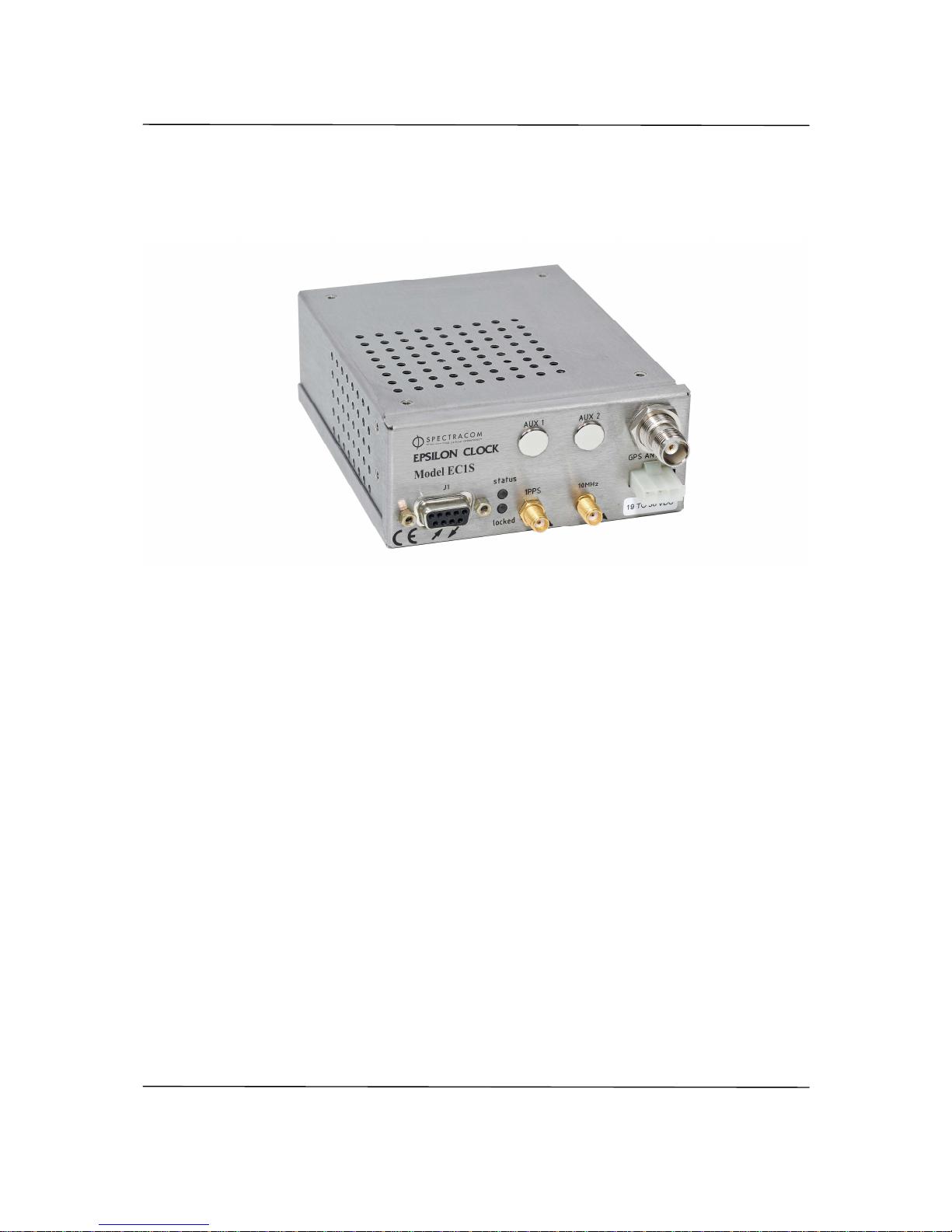
The EPSILON CLOCK MODEL EC1S generates and distributes a highly accurate and stable
frequency source disciplined using GPS input. The clock has autonomous control of GPS
system integrity features (TRAIM) and rejects defective satellites.
The time reference thus obtained is processed by efficient algorithms that control the built-in
oscillator, which generates inner frequency and time signals. The clock continues to distribute
time and frequency signals even if the GPS input signal is lost. Furthermore, “learning” from its
behavior in different situations (effects attributed to aging and to temperature variations) while
the GPS reference signal is present, the frequency driver improves on the accuracy of time and
frequency distribution (when the GPS signal is lost).
The majority of the EPSILON CLOCK MODEL EC1S functions are software controlled. At startup, the clock carries out a series of automatic tests, including hardware tests and verification of
the built-in oscillator stability, before making an initial coarse adjustment to the distributed
frequency. The clock has a serial remote control interface that is used to input all the queries
and commands described in this manual.
THE EPSILON CLOCK MODEL EC1S IS FACTORY CONFIGURED TO ASSUME
AUTOMATIC START-UP AND NORMAL OPERATION WITHOUT USING THE REMOTE
CONTROL INTERFACE.
Page 8

EPSILON CLOCK MODEL EC1S Spectracom Corporation
EPSILON CLOCK User’s Manual 1-2
1.1
1.11.1
1.1 Basic Configuration
Basic ConfigurationBasic Configuration
Basic Configuration
This document is applicable to the EPSILON CLOCK® Model EC1S. In its basic configuration,
the EPSILON CLOCK® Series EC1S is equipped with:
• 1 x GPS antenna input (TNC)
• 1 x DC power supply input (19 to 36 VDC, mini Mate-n-Loc connector)
• 1 x 10 MHz sine-wave output (SMA)
• 1 x 1PPS output (TTL / 50 Ω, SMA)
• 1 x Time Of Day interface (RS232C, SubD 9)
• 1 x remote control interface (RS232C, SubD 9)
• 1 x alarm output (relay contact, SubD 9)
• 2 x LEDs for the status display
Two additional connectors (AUX1 and AUX2) are available for optional inputs or outputs through
the addition of a piggy-back board.
The EPSILON CLOCK MODEL EC1S supports a wide range of oscillators depending on the
customer’s synchronization accuracy needs.
1.2
1.21.2
1.2 Standard Features
Standard FeaturesStandard Features
Standard Features
The EPSILON CLOCK MODEL EC1S is used to generate, maintain, and provide the following:
• A synchronized UTC(GPS) time reference. The clock distributes a 1PPS signal, a Time
Of Day message (TOD interface), and a time-coded message (remote control interface).
• A frequency reference (one sine-wave 10 MHz).
The clock is powered by one DC power supply (19 to 36 VDC)
A remote control interface provides information on clock status and allows the user to send
initialization and configuration commands. The working status of the clock is reported locally
using two LEDs on the front panel.
The relay contact output of the alarm is closed in the event of hardware or software failure.
The EPSILON CLOCK MODEL EC1S is fully automatic. It requires no preventive maintenance.
1.3
1.31.3
1.3 Optional Functions
Optional FunctionsOptional Functions
Optional Functions
The EPSILON CLOCK MODEL EC1S accepts the addition of a piggy-back board to allow
additional inputs or outputs such as:
• Time outputs ( 10MHz, 1PPS, IRIG B)
• SDH / E1 synchronization for SSU functionality and for GPS back-up for excellent
holdover performance
Page 9
Spectracom Corporation EPSILON CLOCK MODEL EC1S
EPSILON CLOCK User’s Manual 1-3
• DDS outputs (2 fixed or 2 software-adjustable frequencies)
1.4
1.41.4
1.4 Oscillators
OscillatorsOscillators
Oscillators
The EPSILON CLOCK MODEL EC1S accepts a wide range of oscillators depending on the
customer’s synchronization accuracy needs.
The standard product uses a High Performance Single Oven OCXO. An optional Double Oven
OCXO is proposed for excellent temperature stability and very low aging. Spectracom also
offers a Low Cost OCXO for less demanding applications (refer to Features).
• EC1S-SO: High Performance Single Oven OCXO
• EC1S-DO: Double Oven OCXO
• EC1S-LC: Low Cost OCXO
Other oscillators can be fitted on request. Contact Spectracom for more information.
1.5
1.51.5
1.5 Inventory
InventoryInventory
Inventory
Before installing your Spectracom product, please verify that all material ordered has been
received. If there is a discrepancy, please contact Spectracom Customer Service. Customer
service is available by telephone at +33 (0) 1.64.53.39.80 (France), or +1.585.321.5800 (United
States). Updated contacts information are available on web site, see “Support” page.
CAUTION: Electronic equipment is sensitive to Electrostatic
Discharge (ESD). Observe all applicable ESD
precautions and safeguards when handling the
Spectracom equipment.
NOTE: If equipment is returned to Spectracom, it must be shipped in its original packing
material. Save all packaging material for this purpose.
1.6
1.61.6
1.6 Inspe
InspeInspe
Inspection
ctionction
ction
Unpack the equipment and inspect it for damage. If any equipment has been damaged in
transit, please contact Spectracom Customer Service. Customer service is available by
telephone at +33 (0) 1.64.53.39.80 (France), or +1.585.321.5800 (United States). Updated
contacts information are available on web site, see “Support” page.
Page 10

EPSILON CLOCK MODEL EC1S Spectracom Corporation
EPSILON CLOCK User’s Manual 1-4
1.7
1.71.7
1.7 Terminology
TerminologyTerminology
Terminology
Auto Survey In automatic mode, the EPSILON CLOCK MODEL EC1S calculates the
position of the antenna and, after testing the result, imposes the position
on the internal GPS receiver. The receiver therefore functions in GPS 0D
reception mode: The EPSILON CLOCK MODEL EC1S is synchronized by
tracking at least one satellite.
DDS Direct Digital Synthesizer
Frequency Driver Frequency signal generated by the built-in oscillator.
GPS Global Positioning System
OCXO Oven Controlled XTAL (Crystal) Oscillator
Rb Rubidium oscillator
S/A Selective Availability
SSU Synchronization Supply Unit
TRAIM Time Receiver Autonomous Integrity Monitoring
UTC Universal Time Coordinated
1PPS One Pulse Per Second
1 PPS Driver Pulse signal obtained through division of the frequency driver
Holdover If the reference input signal is lost, the EPSILON CLOCK® maintains the
generation of information and of time and frequency signals.
Reliability Concerns the positioning mode of the antenna. In automatic mode, the
EPSILON CLOCK® calculates the position of the antenna and, after
testing the result, imposes the reliable position on the internal GPS
receiver. The receiver therefore functions in GPS 0D reception mode. The
EPSILON CLOCK® is synchronized by following at least one satellite.
Frequency driver Frequency signal generated by the built-in oscillator.
Reference input Time and frequency source used by the EPSILON CLOCK®.
IERS International Earth Rotation Service.
Page 11
Spectracom Corporation EPSILON CLOCK MODEL EC1S
EPSILON CLOCK User’s Manual 1-5
1.8
1.81.8
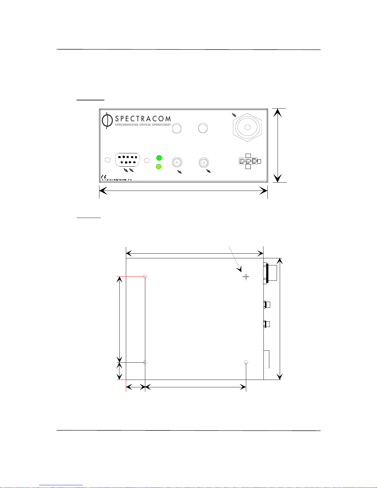
1.8 Mechanical Characteristics (Dimensions in mm)
Mechanical Characteristics (Dimensions in mm)Mechanical Characteristics (Dimensions in mm)
Mechanical Characteristics (Dimensions in mm)
Front side
MADE I N FRANCE BY TEKELEC SYSTEM
J1
1PPS
10MHz
POWER
GPS ANTENNA
status
lock
EPSILON CLOCK
Series 1
T E K E L E C
S Y S T E MES
AUX. 1 AUX. 2
102
41
/ 4.02
/ 1.6
1
Top side
10.7
/ .421
100
/3.94
10.8
/ .425
80
/ 3.15
127
/ 5.00
102
/ 4.0
2
4 mounting hole
M3 s crew
Maximun depth : 10
/ .394
Weight < 600g
Page 12

Page 13

Spectracom Corporation EPSILON CLOCK MODEL EC1S
EPSILON CLOCK User’s Manual
2-1
2222 Installation
InstallationInstallation
Installation
2.1
2.12.1
2.1 Preparing for Use
Preparing for UsePreparing for Use
Preparing for Use
Install the clock in the desired location. To facilitate the installation in user’s equipment, four
mounting holes with M3 screw threads (maximum depth screw 10mm) are provided on the top
of the unit
The clock may be installed in a 19 inch cabinet with two flat angle brackets (refer to Flat Angle
Brackets for more information).
Ideally, the clock should be located for natural air cooling.
CAUTION: Make sure the maximum operating ambient temperature
does not exceed 70°C.
2.2
2.22.2
2.2 Preliminary Connections
Preliminary ConnectionsPreliminary Connections
Preliminary Connections
Before starting the EPSILON CLOCK®, perform the following tasks:
• Position the machine so that the upper and lower air vents are not obstructed.
• Position the GPS antenna outside with an unobstructed view of the sky over 360
degrees (on top of a mast, for example).
CAUTION: The EPSILON CLOCK® is designed to be used with the
supplied GPS antenna ONLY. Using another antenna
may cause significant damage to the unit and will void
your Spectracom warranty.
• Plug the antenna cable into the TNC “Antenna” connector. To ensure the correct
reception of the GPS signal, the overall system of antenna/cable/protection requires a
gain between 15 and 30 dB, with optimum reception around 24 dB.
Page 14

EPSILON CLOCK MODEL EC1S Spectracom Corporation
EPSILON CLOCK User’s Manual 2-2
Example:
GPS
Signals
GPS antenna placed in direct view of the sky
50 m of KX13 cable (-30 dB / 100 m)
G1 = 40 dB
G2 = - 15 dB
EPSILON BOARD II
Lightening protection
G3 = -1 dB
G1 + G2 + G3 = 40 dB - 15 dB - 1 dB = 24 dB
Thus: X
min
dB < G1 + G2 + G3 = 24 dB < X
max
dB
X
min
and X
max
are defined in last updated revision of application note TF2.
• Connect the clock to the main power supply or connect the DC power supply (24V for
the 2S, 48V for the 2T) to the "DC Power" connector (J2).
• The main outlet and every associated extension must provide a protective path to earth
ground. The protection must not be defeated by an extension cord lacking an earth
conductor.
WARNING:
If the protective conductor's path to ground is broken or
defeated, the danger of electrical shock to the operator
may be present.
Before disconnecting the unit from the main power
supply, always switch it off. Failure to do may cause
damage that voids your Spectracom warranty.
2.3
2.32.3
2.3 Connections Quality
Connections QualityConnections Quality
Connections Quality
Great care must be taken in setting up the GPS Antenna and its connections. Remember that
your GPS antenna must have an unobstructed view of the sky.
The type of cable connecting the antenna to the clock and the length of the cable influence
greatly the quality of the signal reception. Cable type and length must conform to the rules
described herein.
Connections to the antenna, the accessories (surge protection, in-line amplifier) and the cable
must be weatherproofed.
EC1S
Page 15

Spectracom Corporation EPSILON CLOCK MODEL EC1S
EPSILON CLOCK User’s Manual
2-3
An improper installation could result in problems ranging from random, intermittent loss of signal
to complete loss of GPS reference. The most common outcome is the inability to discipline the
GPS reference correctly.
2.4
2.42.4
2.4 Power Connection
Power ConnectionPower Connection
Power Connection
The power connector (J1) is an AMP mini mate-n-loc female connector (AMP part number
172329-1) with crimp pin 22-18 AWG (AMP part number 170364-1).
Pin-out
1 +VDC
2 Earth
3 Ret VDC
NOTE: The power supply must be connected between pins 1 and 3.
M ADE IN FR ANC E BY T EK EL E C SY S TE M
J1
1PPS
10MHz
POWER
GPS ANTENNA
status
lock
EPSILON CLOCK
Series 1
T E K E L E C
S Y S T E MES
AUX. 1 AUX. 2
+Vd
c
ret_Vdc
Earth
2.4.1 Mating Power Connector
Use the AMP mate-n-loc mating connectors following:
• Mini mate-n-loc male connector (AMP part number 172337-1) quantity 1
• Crimp socket, 22-18 AWG (AMP part number 170366-1) quantity 3
These connectors are supplied with the clock.
Page 16

EPSILON CLOCK MODEL EC1S Spectracom Corporation
EPSILON CLOCK User’s Manual 2-4
2.4.2 Power Characteristics
Power Supply (VDC): 19 to 36VDC (37 to 72VDC or 10 to 18VDC are available on request,
contact your TEKELEC SYSTEMES sales representatives for further
information).
Consumption:
EC1-LC EC1-SO EC1-DO
Warm-up 7 W 10 W 14 W
Typical 6 W 7 W 11 W
NOTE: The EPSILON CLOCK MODEL EC1S are protected against reverse polarity and is
hot- swappable.
2.5
2.52.5
2.5 Interface connector
Interface connectorInterface connector
Interface connector
The interface connector provides:
• 1 RS232C remote control interface which provides information on clock status and
allows the user to send initialization and configuration commands. This interface
supports direct connections to the RS-232 serial port on a computer. EPSILWIN32 is
Windows software, trademarked to this company, which is designed to monitor and
command the EC1S with an EBO OEM profile. Contact Spectracom for more
information.
• 1 RS232C ToD output (ASCII message of the Time of Day)
• 1 contact relay alarm
Connector: HE501 (Sub D) 9 pin Female
Pin-out
Pin Function Description
1
Not used
2
TC_TX
Transmit line output of the remote control interface.
RS232C level
3
TC_RX
Receive line input of the remote control interface.
RS232C level
4
Not used
5
GND Ground
6
Not used
7
ALARM + Contact of relay alarm
8
ALARM - Contact of relay alarm
9
TOD_TX
Transmit line of the Time Of Day message interface.
RS232C level
Page 17

Spectracom Corporation EPSILON CLOCK MODEL EC1S
EPSILON CLOCK User’s Manual
2-5
2.6
2.62.6
2.6 Starting the Clock
Starting the ClockStarting the Clock
Starting the Clock
Verify that the preliminary connections have been made.
Apply 24 VDC to the mini mate-n-loc connector.
CAUTION:
The green LED “STATUS” is off during the OCXO warmup time (about 20 minutes). For ten seconds after startup, the TOD and Remote Control cannot be used.
The two front panel green LEDs are used to report the status of the clock. During start-up, the
LED sequence is as follows:
Locked STATUS Notes
Standard hardware
automatic test
“off” “off” Checks the basic features of the clock
GPS hardware test “on” “off” Checks GPS features
Period of
synchronization
“off” “on” Searching for signal transmitted by
GPS satellites
Synchronization “on” “on” The distributed time is synchronized
to UTC
(GPS)
In case of hardware or software failure, the “STATUS” led is “off” and the alarm output (on J1) is
“on” (relay contact closed).
The conditions for activating this output are as follows:
• Faulty GPS receiver
• Faulty frequency driver
• Faulty frequency divider loop
• Faulty distribution of frequency or synchronization signals
• Faulty frequency or synchronization performances (a parameter that can be selected via
the remote control interface).
If the failure occurs after the start-up sequence, both LEDs are “off”. In this state, the Time Of
Day message is not distributed and the clock will not be synchronized to the GPS source. If this
occurs, contact Spectracom.
Under normal operating conditions, the EPSILON CLOCK MODEL EC1S is synchronized to
UTC
(GPS)
about 25 minutes after it is switched on. When it is synchronized, both LEDs are
“on”.
Page 18

EPSILON CLOCK MODEL EC1S Spectracom Corporation
EPSILON CLOCK User’s Manual 2-6
In this state, the EPSILON CLOCK MODEL EC1S continuously delivers the following outputs
slaved to the UTC
(GPS)
reference:
• The 1PPS output and the associated Time Of Day message output
• The frequency output
2.7
2.72.7
2.7 Turning Off the Clock
Turning Off the ClockTurning Off the Clock
Turning Off the Clock
To turn off the EPSILON CLOCK®, remove power input.
Page 19

Spectracom Corporation EPSILON CLOCK MODEL EC1S
EPSILON CLOCK User’s Manual
3-1
3333 Features
FeaturesFeatures
Features
3.1
3.13.1
3.1 Frequency Output
Frequency OutputFrequency Output
Frequency Output
Connectors: 10MHz SMA Female
Pin Settings
Center contact: Sine-wave signal
Outer contact: Ground
Signal characteristics:
EC1S-LC EC1S-SO EC1S-DO
Signal waveform
1 x 10 MHz, sine-wave
Typical level
5 dBm load 50 Ω
Harmonic distortion / duty cycle
-25 dBc -40 dBc
Accuracy (Average over 24 hours
when GPS locked)
< ± 1 x 10
-11
< ± 2 x 10
-12
< ± 1 x 10
-12
Medium stability (without GPS,
constant temperature, after 2 weeks of
continuous operation)
5 x 10⁻⁹ /day 2 x 10
-10
/day 1 x 10
-10
/day
Short term stability (Allan variance) @
1s
@10s
@100s
2 x 10
-11
6 x 10
-11
6 x 10
-11
1 x 10
-11
3 x 10
-11
3 x 10
-11
5 x 10
-12
1 x 10
-11
1 x 10
-11
Temperature stability (peak to peak)
1 x 10
-7
(from 10 to
30°C)
1 x 10
-9
(from 0 to
60°C)
2 x 10
-10
(from –5 to
70°C)
Phase noise (typical, static
conditions) 10 Hz
100 Hz
1 kHz
10 kHz
100 kHz
-100 dBc / Hz
-120 dBc / Hz
-140 dBc / Hz
-145 dBc / Hz
-145 dBc / Hz
-120 dBc / Hz
-130 dBc / Hz
-140 dBc / Hz
-145 dBc / Hz
-145 dBc / Hz
-120 dBc / Hz
-130 dBc / Hz
-145 dBc / Hz
-145 dBc / Hz
-145 dBc / Hz
Page 20

EPSILON CLOCK MODEL EC1S Spectracom Corporation
EPSILON CLOCK User’s Manual 3-2
3.2
3.23.2
3.2 1PPS Output
1PPS Output1PPS Output
1PPS Output
Connector: PPS SMA Female
Pin Settings
Center contact: Periodic pulse
Outer contact: Electrical ground of the “GND” pins.
Signal characteristics:
EC1S-LC EC1S-SO EC1S-DO
Signal waveform High-level
Low level
> 2.4 V load 50Ω
< 0.8 V load 50Ω
Period
1s
Active edge
rising
Rising edge duration
< 20 ns load 50Ω
Pulse duration
100µs ± 10µs
Accuracy to UTC, GPS locked ± 100 ns (1σ) ± 25 ns (1σ) ± 25 ns (1σ)
Holdover mode after 4 hours
1day
(at constant temperature, after 24
hours of GPS lock and 2 weeks of
continuous operation)
30 µs
200 µs
0.8 µs
12 µs
0.6 µs
7 µs
If required, the squelch function of the1 PPS output can be implemented on the EC1S. This
requires the user to download an alternative firmware version (to be checked with the
factory).
If this function is available, the 1 PPS distribution stops in case of alarm.
3.3
3.33.3
3.3 Remote Control Interface (RS232C)
Remote Control Interface (RS232C)Remote Control Interface (RS232C)
Remote Control Interface (RS232C)
Serial port parameters: 9600 bps, 8 bits, 1 stop bit, odd parity
Protocol / syntax / format of messages: Refer to Remote Control Interface
Data: Binary (two's complement)
Order of bytes emitted: Most significant bytes first
Connector J1: Sub D (HE501) 9-pin female
Pin settings:
Pin Setting
2 Transmit remote signal
3 Receive remote signal
5 Ground
Page 21

Spectracom Corporation EPSILON CLOCK MODEL EC1S
EPSILON CLOCK User’s Manual
3-3
3.4
3.43.4
3.4 TOD Output
TOD Output TOD Output
TOD Output
Time Of Day message output:
Output: ASCII, 9600 bps, 8 bits, 1 stop bit, odd parity.
Protocole: <Message> CR LF
Format*: Day/Month/Year Hour: Minute: Second Source
e.g.: 20/03/1996_21:02:05U
Format*: Month/Day/Year Hour: Minute: Second Source
e.g.: 11/12/1996_18:14:38L
Format*: Day of Year/Year Hour: Minute: Second Source
e.g.: 317/1996_18:16:20 L
Format*: MJD** - Integer part Hour: Minute: Second Source
e.g.: _ _ _ _ _ _50399.18:20:50_U
Format*: MJD** Source
e.g.: _ _ _ _ _ _50399.762130_L
The "Source" byte holds one ASCII character which codes the reference of the time chosen
N No reference
U UTC reference
G GPS reference
L Local time
M Manual
- Maximum output period*: 1 message per second
- Output synchronization: sent at 200 ms ±100 ms after the 1PPS signal.
* Programmable through the remote control interface.
** Modified Julian Day
Connectors: J1 Sub D (HE501) 9-pin female
Mini Din 6 pins Female
Pin settings:
Pin Setting
9 Time Of Day message Output
5 Ground
Page 22

EPSILON CLOCK MODEL EC1S Spectracom Corporation
EPSILON CLOCK User’s Manual 3-4
3.5
3.53.5
3.5 Alarm Output
Alarm OutputAlarm Output
Alarm Output
If required, the polarity of the relay can be reversed.
Type: Relay contact
Closed in a case of hardware or software failure (Standard configuration)
Open in a case of hardware or software failure (On requirement)
Resistive Contact Rating: 30VA / 250V
Connector: J1 Sub D (HE501) 9 pin female
Pin settings:
- 7: ALARM +
- 8: ALARM -
3.6
3.63.6
3.6 Power Supply
Power Supply Power Supply
Power Supply
Power supply (VDC): 19 to 36 VDC on standard
10 to 18VDC or 37 to 72VDC on request
Protection: Reverse polarity
Hot swap insertion
Polyswitch against short-circuit
Consumption:
EC1-LC EC1-SO EC1-DO
Warm-up 7 W 10 W 14 W
Typical 6 W 7 W 11 W
Connector: POWER AMP mini Mate-n-Loc female connector (AMP part number 172329-1)
with crimp pin 26-22 AWG (AMP part number 170363-1)
Pin Settings
- 1: +VDC
- 2: Earth
- 3: -VDC
Page 23

Spectracom Corporation EPSILON CLOCK MODEL EC1S
EPSILON CLOCK User’s Manual
3-5
3.7
3.73.7
3.7 GPS Antenna Input/Out
GPS Antenna Input/Out GPS Antenna Input/Out
GPS Antenna Input/Output
putput
put
Connector: ANTENNA TNC female
Pin Settings
Center contact: GPS Signal Input (L1)
Output power supply of the active antenna:
Voltage: 5V
Current: 80 mA max.
Outer contact: Electrical ground of the “GND” pins.
3.8
3.83.8
3.8 Operating Environment
Operating EnvironmentOperating Environment
Operating Environment
EC1S-LC EC1S-SO EC1S-DO
Operating temperature -5°C to 60°C
Storage temperature - 40°C to 85°C
Relative humidity 95 % non condensing
CE compliant EN 300 386 / EN 55022 / EN 60950
Page 24

EPSILON CLOCK MODEL EC1S Spectracom Corporation
EPSILON CLOCK User’s Manual 3-6
Page 25

Spectracom Corporation EPSILON CLOCK MODEL EC1S
EPSILON CLOCK User’s Manual
4-1
4444 SDH/E1 Option
SDH/E1 OptionSDH/E1 Option
SDH/E1 Option
When installed, this option provides:
• SDH / E1 synchronization for SSU functionality such as ITU G.811 GPS PRC when
locked on GPS
• GPS back-up to provide excellent holdover performance.
This option is for the EC1S-SO and EC1S-DO.
4.1
4.14.1
4.1 2.048 MHz Output
2.048 MHz Output2.048 MHz Output
2.048 MHz Output
Connector: AUX2 SMA Female
Pin Settings
Center contact: Sine-wave signal
Outer contact: Ground
Signal characteristics:
- G.703 § 13 / 75 Ω
- MTIE / TDEV: Meets the ITU G.811 recommendations when GPS-locked
4.2
4.24.2
4.2 2.048 MHz Input
2.048 MHz Input2.048 MHz Input
2.048 MHz Input
The EPSILON CLOCK MODEL EC1S can be synchronized with an external input 2.048MHz
when GPS is lost. This yields excellent holdover performance.
Before all switching, the EPSILON CLOCK MODEL EC1S must be locked on GPS at least one
hour to allows a good 1PPS synchronization to the UTC.
After this delay, if an external reference is connected, the EPSILON CLOCK MODEL EC1S
switch automatically on this last as soon as the GPS is lost. The led “locked” is blinking . The
1PPS and frequency drifts are in accordance with the external input 2.048MHz medium term
accuracy.
The 1PPS timing performances are again guaranty respect to UTC, ½ hour after the GPS is
back.
Page 26

EPSILON CLOCK MODEL EC1S Spectracom Corporation
EPSILON CLOCK User’s Manual 4-2
Connector: AUX1 SMA Female
Pin Settings
Center contact: Sine-wave signal
Outer contact : Ground
Signal characteristics:
- Signal level: G.703 § 13 / 75 Ω unbalanced.
- Input jitter & wander tolerances: Compliant with G811 and ESTI EN 300 462-4/6
recommendations.
Page 27

Spectracom Corporation EPSILON CLOCK MODEL EC1S
EPSILON CLOCK User’s Manual
5-1
5555 Remote Control Interface
Remote Control InterfaceRemote Control Interface
Remote Control Interface
5.1
5.15.1
5.1 General
GeneralGeneral
General
The remote control interface allows remote configuration and remote status reporting of the
clock. The RS232C connection operates at 9600 bps and is set to 8 bits, 1 stop bit, and odd
parity.
5.2
5.25.2
5.2 Protocol
ProtocolProtocol
Protocol
The protocol used is Master (Host) / Slave (EPSILON CLOCK®) with a systematic reply to all
messages. The following exceptions apply (for which no reply is expected):
• The time code message sent periodically
• The reset clock command
All messages start with the "STX" character and end with the "ETX" character.
e.g.: <STX> <Message> <ETX>
The characters “ STX ”, “ ETX ” or “ DLE ” to be sent within a message should be escaped
(prefixed) by the "DLE" character.
Each message contains four distinct sections:
• The message “ID” (this identifies the type of message being sent):
• The count of the number of data bytes in the message (CNT),
• The data bytes (DATA
(*)
) of the message,
• The checksum: calculated by performing an exclusive OR on all the consecutive
characters in the message (ID + CNT + DATA)
e.g.: <Message> = <ID> <CNT > <DATA
(*)
> <CS>
Number of bytes 1 1 N 1
(*): The encoding format of the DATA is based on “MOTOROLA big Endian” type (integer, long,
float, and double data must be sent or received with the MSB first).
NOTE: The maximum length of the <DATA> section is 255 bytes.
Messages belong to one of three categories:
• Queries (requests for information from the EPSILON CLOCK®)
• Commands (functions that initialize or configure the EPSILON CLOCK®)
• Error Messages (returned by the clock if errors are detected in the Queries or
Commands sent by the user)
When a user sends a message to the EPSILON CLOCK®, it replies within the current second.
This reply, or acknowledgement, is formatted as follows:
• The format of the message is identical to the message sent by the user
Page 28

EPSILON CLOCK MODEL EC1S Spectracom Corporation
EPSILON CLOCK User’s Manual 5-2
• The contents of sections <ID> and <CNT> are identical to those sent by the user
• The content of the <DATA > section:
o Is identical to that sent by the user if the message was a Command
o Contains the information supplied by the clock, if the message was a Query
The acknowledgement to a Command is an exact copy of the message sent.
The reply to a Query is the copy of the Query message with the <DATA> section completed by
the EPSILON CLOCK®. In a query, the <DATA> field is not taken into account by the EPSILON
CLOCK® command interpreter.
An Error message is generated by the clock if one of the following errors occurs:
• The message contains an unknown ID
• The number of bytes in the <DATA> section does not correspond to the <CNT> value
• An overflow is detected in a parameter within the <DATA> section
NOTE: If the clock detects a checksum error, it does not take into account the message
and it does not transmit any error message.
5.3
5.35.3
5.3 Commands description
Commands descriptionCommands description
Commands description
5.3.1 TOD output setup
This command allows the user to modify the contents of the periodical messages transmitted by
the clock on the TOD output. In standard mode, the default message transmitted contains the
current date and hour according to the codes provided herein. In diagnostic mode, the message
transmitted contains information regarding the disciplining of the frequency driver to the GPS
reference. This mode is used by the manufacturer during the “good” working verification phases.
5.3.2 TOD output transmission period
This command defines the transmission period to the TOD message on the corresponding
special link. This period is quantified in seconds; the value 0 inhibits permanently the
transmission of the message.
5.3.3 Clock reset
This command generates the re-initialization of the clock.
5.3.4 GPS mode setup
This command defines the clock functioning mode with regards to the GPS signals received.
Three modes are available: Automatic, Manual, or Mobile.
The Automatic mode is the default mode during the clock initialization. In this mode, the clock
averages during 1 hour the antenna position supplied by the receiver in order to make it reliable.
After this period and providing that a minimum of 4 satellites were received at all times, the
position is fixed and the clock requires only one satellite for time transfer. This 1 hour reliability
procedure of the position is initialized every time the clock is switched on and is maintained as
long as a minimum of 4 satellites are not received continuously.
Page 29

Spectracom Corporation EPSILON CLOCK MODEL EC1S
EPSILON CLOCK User’s Manual
5-3
The manual mode allows the user to instantaneously force the GPS receiver to function in one
satellite mode. The user is required to enter the date and the geographic position of the
antenna.
The Mobile mode is useful when the clock is moved while functioning. This command prevents
the GPS receiver from switching to the 1 satellite mode. It is therefore necessary in this case to
receive a minimum of 4 satellites continuously to ensure a good disciplining of the frequency
source.
5.3.5 GPS positioning
This command allows the initialization of the antenna position. This is necessary in Manual
mode. This command also allows the user to define which time reference is used. The two
possibilities are as follows:
• The Universal Time Coordinated,
• The GPS Atomic Time.
The difference between these two time references is equal to a whole number of seconds,
which changes with every leap second insertion in the UTC reference.
The GPS Atomic Time reference is recommended when the user's application requires a
perfectly continuous time reference. In effect, the GPS Atomic Time is not subject to leap
second insertion.
5.3.6 Local time
The cable between the antenna and the clock generates a propagation delay of the GPS signal.
This delay corresponds to a time shift of the synchronizing signal. This time shift can be
compensated for using this command. The correction is entered in nanoseconds, and the value
corresponding to the delay is linked to the type of cable and its length. As a rule of thumb, the
value for the delay of a coaxial cable is about 5 nano seconds per meter.
5.3.7 Antenna delay correction (phase correction)
The cable between the antenna and the clock generates a propagation delay of the GPS signal.
This delay corresponds to a time shift of the synchronizing signal. This time shift can be
compensated for using this command. The correction is entered in nanoseconds, and the value
corresponding to the delay is linked to the type of cable and its length. As a general rule of
thumb, the value for the delay of a coaxial cable is about 5 nanoseconds per meter.
5.3.8 Leap second
The UTC time reference, maintained by the GPS clock, is subject to leap second corrections,
the purpose of which is to maintain the difference between the atomic time represented by UTC
and the astronomic time. These corrections decided by the IERS are published in Bulletin C and
D.
If the time reference used by the clock is UTC, these corrections are automatically made in real
time provided the GPS signal is received correctly. This command allows the clock to maintain a
Page 30

EPSILON CLOCK MODEL EC1S Spectracom Corporation
EPSILON CLOCK User’s Manual 5-4
reliable time reference by programming in advance the leap second correction, ensuring it will
be applied even in the case of loss of GPS signal input.
This command does not apply to the other time references.
5.3.9 Force holdover mode
The initial functioning mode of the clock is always synchronized on the GPS reception.
However, the user may configure the clock in the holdover mode, specifically, the disciplining of
the driver frequency and if the 1 PPS is stopped.
5.3.10 Display
This command defines the format of the hour transmitted by the TOD message and displayed
on the front panel display screen if this option was chosen.
The five formats available are as follows:
• Day / Month / Year Hour: Minute: Second
• Month / Day / Year Hour: Minute: Second
• Day of year / Year Hour: Minute: Second
• MJD (Modified Julian Day)
• MJD integer part Hour: Minute: Second
With this command, the user defines whether the output of the hour is issued from the UTC or
GPS time reference, or from the local hour with the programmed shift.
5.3.11 Alarms limits
If the GPS input signal is lost, the clock's internal oscillator is no longer disciplined. The
frequency accuracy and the distributed synchronization start to degrade slowly according to the
ageing of the oscillator.
Using the alarms limits commands, the user may define the accuracy limits outside of which the
output signals are deemed invalid. These limit values are in the form of a time difference for the
1 PPS and in the form of a relative frequency difference for the frequency outputs.
When these limit values are reached, a fault is generated, the LED “STATUS” is fixed “off,” and
the contact relay is closed.
Page 31

Spectracom Corporation EPSILON CLOCK MODEL EC1S
EPSILON CLOCK User’s Manual
5-5
5.4
5.45.4
5.4 Time distribution on the remote control interface
Time distribution on the remote control interface Time distribution on the remote control interface
Time distribution on the remote control interface
The time message is transmitted to the remote control interface. The format and the output TOD
are selected by the "display" function. The transmission is synchronous with the 1PPS.
Format 1: ID: 193
CNT: 8
DATA: day/month/year/hour/min/sec/source
Format 2: ID: 194
CNT: 8
DATA: day/month/year/hour/min/sec/source
Format 3: ID: 195
CNT: 8
DATA: Day of Year/year/hour/min/sec/source
Format 4: ID: 196
CNT: 9
DATA: MJD/source
Format 5: ID: 197
CNT: 8
DATA: MJD integer part/hour/min/sec/source
The "Source" byte holds an ASCII character, which codes the time reference:
N No reference
U UTC reference
G GPS reference
L Local time
M Manual
Encoding type:
Day : char
Month : char
Year : integer (2 bytes)
Min : char
Sec : char
source : char
MJD integer part : long (4 bytes)
MJD : double (8 bytes)
Page 32

EPSILON CLOCK MODEL EC1S Spectracom Corporation
EPSILON CLOCK User’s Manual 5-6
5.5
5.55.5
5.5 Command or query syntax
Command or query syntaxCommand or query syntax
Command or query syntax
Designation Command
ID
query ID Number of
bytes
Command
validity conditions
TOD output setup 1 65 1 (1)
Status --- 80 37 (1)
Emission period of the time message on the
TOD interface and on the remote control
interface
2 66 4
Reset 16 --- 0 (1)
GPS Date init 4 68 7 (1)
Local Time 7 71 2 (1) et (3)
Phase Correction 8 72 4 (1) et (3)
Leap Second 9 73 6 (1) et (4)
GPS Positioning 10 74 19 (1) et (3)
Display 13 77 2 (1)
Alarm limits 14 78 10 (1)
Version --- 67 10 (1)
Forced holdover mode 15 79 1 (1)
Manual time setting 17 81 7 (1) et (5)
Manual correction ±1s
21 85 1 (1) et (5)
Remote control mode 18 82 1 (2)
(1): Command authorized if the clock is in remote control mode.
(2): Command always authorized.
(3): Command authorized if the clock is not in forced holdover mode.
(4): Command authorized if the current time reference is UTC.
(5): Command authorized if the clock is in forced holdover mode.
The tables that follow contain the format of the commands and the requests.
Page 33

Spectracom Corporation EPSILON CLOCK MODEL EC1S
EPSILON CLOCK User’s Manual 5-7
Name Identifier
Bytes Byte
No.
Encode
Type
Settings Description
Query Command
Status
80 - 37 0 to 3 1 long b0 = 1
b0 = 0
Clock is synchronized to the reference input (GPS)
Clock is not synchronized (the clock is in hold over mode after the loss of the reference
input signal).
b1 to b7 Reserved bits.
b8 = 1
b8 = 0
GPS 1PPS failure.
GPS 1PPS operational.
b9 = 1
b9 = 0
Frequency driver failure.
Frequency driver operational.
b10 = 1
b10 = 0
1PPS driver failure.
1PPS driver operational.
b11 0 Reserved bit.
b12 = 1
b12 = 0
1PPS output failure.
1PPS output operational.
b13 = 1
b13 = 0
Phase limit alarm: loss of synchronization, programmed phase-limit exceeded.
Phase limit not exceeded.
b14 = 1
b14 = 0
Frequency or limit alarm: loss of synchronization (if the programmed limit is set to 0) or
loss of synchronization and limit exceeded or synchronization period too short to
provide the programmed frequency limit.
Programmed frequency or limit not exceeded: the clock is synchronized during a period
of time sufficient enough to provide the frequency inside the programmed limit or the
loss of synchronization is not sufficiently long to exceed the programmed limit.
b15 Reserved bit
b16 = 1
b16 = 0
EPSILON CLOCK MODEL EC1S hardware failure.
EPSILON CLOCK MODEL EC1S hardware operational.
b17 Reserved
b18 = 1
b18 = 0
Antenna not connected.
Antenna connected.
b19 = 1
b19 = 0
Antenna short circuit alarm.
No antenna short circuit.
b20 to b31 Reserved
4 1 char Char value: 1 or 5 GPS reception, mode 0D:
The EPSILON CLOCK MODEL EC1S is synchronized using a single satellite.
Mode set to manual positioning of the GPS antenna or after auto survey of the GPS
antenna coordinates in automatic positioning mode.
Char value: 2 or 6 GPS reception mode 2D:
The EPSILON CLOCK MODEL EC1S is synchronized using 3 satellites.
This mode can only operate if the antenna positioning mode is set to mobile, or
automatic and when the auto survey is in progress.
Char value: 3 or 7 GPS reception mode 3D:
The EPSILON CLOCK MODEL EC1S is synchronized using 4 or more satellites and
the antenna positioning mode is set to mobile, or automatic and when the auto survey
is in progress.
Page 34

EPSILON CLOCK MODEL EC1S Spectracom Corporation
EPSILON CLOCK User’s Manual 5-8
Name Identifier
Bytes Byte
No.
Encode
Type
Settings Description
Query Command
5 to 20 8
integers
Odd bytes (5 to 19) For each byte, the number of the satellite being tracked is set on bits b0 to b6. The
locking to satellite indicator is given by bit b7 (b7=0 ; locked).
Even bytes (6 to 20) SNR (0 to 255) of the followed satellites.
The even byte Oi gives the SNR of the satellite indicated by the byte O
i-1
e.g.: O3 = 140 (80 HEX + 12 decimal) O4 = 120
Satellite 12 is locked and its SNR is 120.
21 to 22 1 integer --- Reserved
23 to 26 1 long -324,000,000 ... 324,000,000
(-90° S ... +90° N)
Latitude of the GPS antenna (ms) in WGS 84 Datum Ellipsoid.
27 to 30 1 long -648,000,000 ... 648,000,000
(-180° W .. +180° E)
Longitude of the GPS antenna (ms) in WGS 84 Datum Ellipsoid.
31 to 34 1 long -100,000 ... 1,800,000
(-1,000 m to 18,000 m)
Altitude of the GPS antenna (cm) in WGS 84 Datum Ellipsoid.
35 1 char 1
0
GPS receiver failure
GPS receiver operational.
36 1 char --- Reserved
TOD output
setup
65 1 1 0 1 char 1
0
Clock diagnostic output.
TOD message output.
Time
message
period of
emission
66 2 4 0 to 3 1 long 0 ... 100,000
(0 ... 100,000 sec)
Period of the emission of the time message on the TOD interface and on the remote
control interface.
Reset of the
clock
--- 16 0 --- --- Stops and restarts the clock (warm-reboot).
GPS date int 68 4 7 0 1 char 1 ... 31 (Days) Sets the GPS receiver date and time.
1 1 char 1 to 12 (Months)
2 to 3 1 integer 1992 ... 2016 (Years)
4 1 char 0 ...23 (hours)
5 1 char 0 ... 59 (minutes)
6 1 char 0 ... 59 (seconds)
Page 35

Spectracom Corporation EPSILON CLOCK MODEL EC1S
EPSILON CLOCK User’s Manual 5-9
Name Identifier
Bytes Byte
No.
Encode
Type
Settings Description
Query Command
GPS
positioning
74 10 19 0 1 char 1
2
3
Antenna positioning mode: Automatic
Antenna positioning mode: Manual
Antenna positioning mode: Mobile
1 to 4 1 long -324,000,000 ... 324,000,000
(-90° S ... +90° N)
Latitude (ms) in WGS 84 Datum Ellipsoid.
5 to 8 1 long -648,000,000 ... 648,000,000
(-180° W .. +180° E)
Longitude (ms) in WGS 84 Datum Ellipsoid.
9 to 12 1 long -100,000 ... 1,800,000
(-1,000 m to 18,000 m)
Altitude (cm) in WGS 84 Datum Ellipsoid.
13 to 17 5 char --- Reserved
18 1 char 1
0
UTC time scale reference.
GPS time scale reference.
Local time 71 7 2 0 1 char -23 ... +23 (hours) Difference, in hours and minutes, between local time and the clock reference time.
1 1 char -59 ... +59 (minutes)
Phase
correction
72 8 4 0 to 3 1 long 0 ... 1,000 ns Programmed difference between the distributed 1PPS signal and the built-in reference
(to correct antenna cable delay).
Leap second 73 9 6 0 1 char 1
0
No leap second.
Use leap second.
1 1 char 1
2
Leap second addition.
Leap second subtraction.
2 to 3 1 integer 1 ... 366 Days Day of the year to be used.
4 to 5 1 integer 1992 ... 2127 Year to be used
Display 77 13 2 0 1 char 0 Day / Month / Year format
1 Month / Day / Year format
2 Day of year / Year format
3 MJD format
4 MJD format integer part hh/mn/sec
1 1 char --- Reserved
Alarm limits 78 14 10 0 to 3 1 long
0 ... 1,000 µs
Phase alarm limit
0 = no phase alarm.
4 to 7 1 long 0 ... 1,000 10-9 Frequency alarm limit
0 = alarm immediate if synchronization is lost.
8 to 9 1 integer --- Reserved
Page 36

EPSILON CLOCK MODEL EC1S Spectracom Corporation
EPSILON CLOCK User’s Manual 5-10
Name Identifier
Bytes Byte
No.
Encode
Type
Settings Description
Query Command
Version 67 10 0 to 3 1 long --- Reserved
4 1 char 0 ... 255 Software version.
5 1 char 0 ... 255 Update version number.
6 to 9 1 integer --- Reserved
8 1 char EPLD version number
9 1 char --- Reserved
Error
(ID = 64)
2 0 1 char X Invalid message ID
1 1 char 0 Incorrect number of useful bytes
1 Unknown message ID
2 Unauthorized parameter in <DATA> section.
3 Command not valid
4 Remote command not authorized
Forced
holdover
mode
79 15 1 0 1 char 1
0
Functioning mode: disciplining authorized
Functioning mode: holdover forced
Manual time
setting
81 17 7 0 1 char 1 ... 31 (days) Manual setting of the clock (authorized only in forced holdover mode).
1 1 char 1 ... 12 (months)
2 to 3 1 integer 1992 ... 2127 (years)
4 1 char 0 ...23 (hours)
5 1 char 0 ... 59 (minutes)
6 1 char 0 ... 59 (seconds)
Manual
correction
±1s
85 21 1 0 1 char 1: - 1 second
0: + 1 second
Manual second correction (authorized only in forced holdover mode).
Remote
control
mode
82 18 1 0 1 char 0: remote control mode
authorized
1: remote control not authorized
Authorization or not of new remote control commands.
Page 37

Spectracom Corporation EPSILON CLOCK MODEL EC1S
EPSILON CLOCK User’s Manual
6-1
6666 Flat Angle Brackets
Flat Angle BracketsFlat Angle Brackets
Flat Angle Brackets
The Epsilon clock EC1S accepts two flat angle brackets for installation inside a 19 inch cabinet.
Two methods of installation are possible:
• Front of the cabinet
• Inside the cabinet
6.1
6.16.1
6.1 Front of the Cabinet
Front of the CabinetFront of the Cabinet
Front of the Cabinet
19 inch cabinet
TOP SIDE
EC1S
Left flat angle
bracket
Right flat angle
bracket
RIGHT SIDE
2 x M3 SCREW
(maximum death screw 10mm)
Page 38

EPSILON CLOCK MODEL EC1S Spectracom Corporation
EPSILON CLOCK User’s Manual 6-2
6.2
6.26.2
6.2 Inside the Cabinet
Inside the CabinetInside the Cabinet
Inside the Cabinet
19 inch cabinet
1pps cable
10MHz cable
GPS cable
EC1S
Left flat angle
bracket
Right flat angle
bracket
TOP SIDE
RIGHT SIDE
2 x M3 SCREW
(maximum death screw 10mm)
Page 39

Spectracom Corporation EPSILON CLOCK MODEL EC1S
EPSILON CLOCK User’s Manual
7-1
7777 Interconnection SAS Cables Kit
Interconnection SAS Cables KitInterconnection SAS Cables Kit
Interconnection SAS Cables Kit
This section describes how to interface the εSAS with two EC1S units, using the interconnection
SAS cables kit.
7.1
7.17.1
7.1 Composition
CompositionComposition
Composition
The interconnection SAS cables kit includes:
4 BNC-SMA RG58 cable length 1,5m
BNC Male
SMA Male
2 SubD-Minijack cable length 1,5m
SUB D 9 POINTS
male
SUB D 9 POINTS
female
Mini jack plug 3.5mm
7.2
7.27.2
7.2 Procedur
ProcedurProcedur
Procedureeee
1) First, make sure that the εSAS doesn’t monitor the TOD (refer to the εSAS instruction
manual).Other signals must be monitored.
2) Connect the 1PPS of EC1S A on connector J1 of the εSAS with a BNC-SMA cable.
3) Connect the 10MHz of EC1S A on connector J2 of the εSAS with a BNC-SMA cable.
4) Connect the J1 of EC1S A on connector J4 of the εSAS with a SubD-MiniJack cable.
NOTE: The SubD 9-pin female connector on this cable provides direct access on the
RS232 remote control interface of the EC1S when this cable is connected on J1.
5) Connect the 1PPS of EC1S B on connector J30 of the εSAS with a BNC-SMA cable.
6) Connect the 10MHz of EC1S B on connector J29 of the εSAS with a BNC-SMA cable.
7) Connect the J1 of EC1S B on connector J27 of the εSAS with a SubD-MiniJack cable.
Page 40

EPSILON CLOCK MODEL EC1S Spectracom Corporation
EPSILON CLOCK User’s Manual 7-2
NOTE: The SubD 9-pin female connector on this cable provides direct access on the
RS232 remote control interface of the EC1S when this cable is connected on J1.
Page 41

Spectracom Corporation EPSILON CLOCK MODEL EC1S
EPSILON CLOCK User’s Manual
7-3
Page 42

REVISION HISTORY
Revision
Level
ECN
Number
Description
A 01/12/03 Creation / First draft
B 01/04/04 Power connection
C 15/09/04
Phase noise / Mechanical characteristics
SDH/E1 option, interconnection SAS cables kit
D0 09/06/08
First iteration of this Spectracom documentation, converted from
previous documentation.
Page 43

Spectracom Corporation
95 Methodist Hill Drive
Rochester, NY 14623
www.spectracomcorp.com
Phone: US +1.585.321.5800
Fax: US +1.585.321.5219
3 Avenue du Canada
91974 Les Ulis, France
www.spectracom.fr
Phone: +33(0)1.64.53.39.80
Fax: +33(0)1.64.53.39.81
 Loading...