

Page 1

MODEL 8144-DD
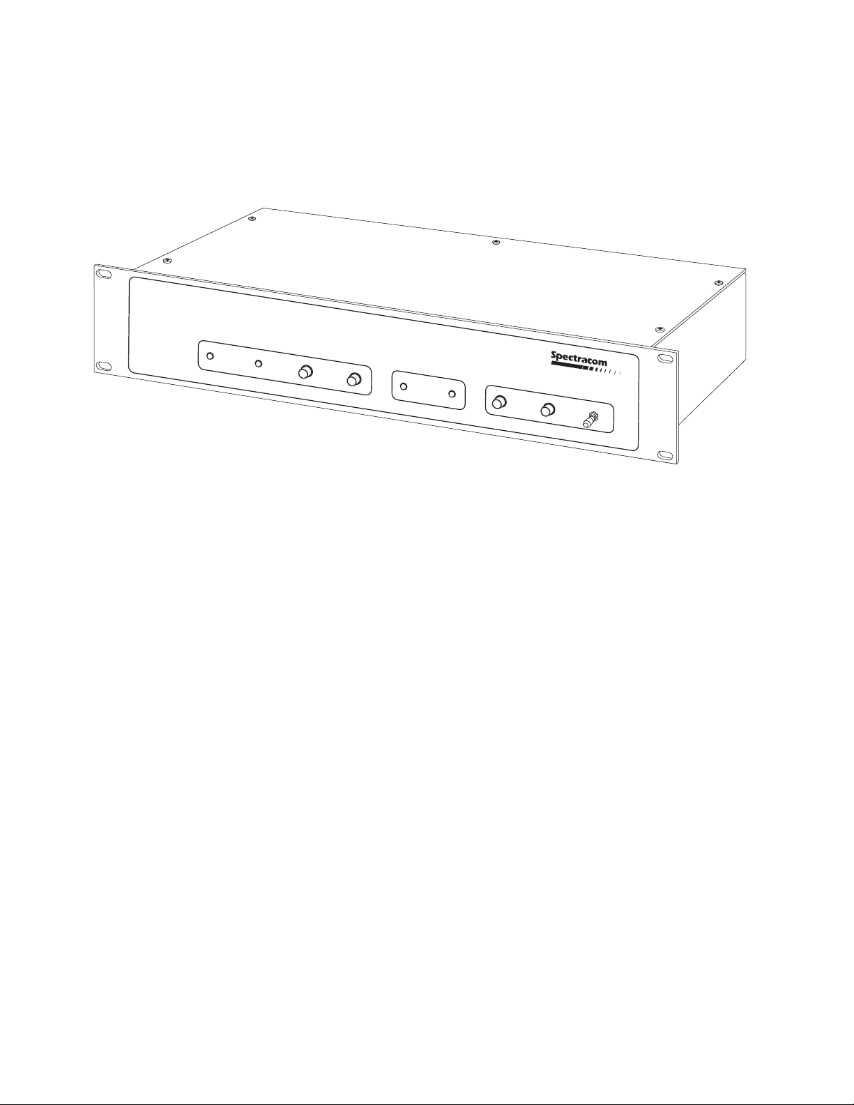
Clock Selector/Distribution Amplifier
Instruction Manual
SPECTRACOM CORPORATION
95 Methodist Hill Drive, Suite 500
Rochester, NY 14623
Phone 585.321.5800
Fax 585.321.5219
www.spectracomcorp.com
REVISIONS, IF ANY, ARE LOCATED AT THE END OF THE MANUAL
REVISION A
December 2003
(Model 8144-DD/075020)
Page 2

5-Year Warranty
LIMITED WARRANTY________________________________
Spectracom warrants each new product manufactured and sold by
it to be free from defects in material, workmanship, and
construction, except for batteries, fuses, or other material normally
consumed in operation that may be contained therein, for five
years after shipment to the original purchaser (which period is
referred to as the "warranty period"). This warranty shall not
apply if the product is used contrary to the instructions in its
manual or is otherwise subjected to misuse, abnormal operations,
accident, lightning or transient surge, repairs or modifications not
performed by Spectracom.
The GPS receiver is warranted for one year from date of shipment
and subject to the exceptions listed above. The power adaptor, if
supplied, is warranted for one year from date of shipment and
subject to the exceptions listed above.
The Rubidium oscillator, if supplied, is warranted for two years
from date of shipment and subject to the exceptions listed above.
All other items and pieces of equipment not specified above,
including the antenna unit, antenna surge suppressor and antenna
pre-amplifier are warranted for 5 years, subject to the exceptions
listed above.
WARRANTY CLAIMS________________________________
Spectracom's obligation under this warranty is limited to in-factory
service and repair, at Spectracom's option, of the product or the
component thereof, which is found to be defective. If in
Spectracom's judgment the defective condition in a Spectracom
product is for a cause listed above for which Spectracom is not
responsible, Spectracom will make the repairs or replacement of
components and charge its then current price, which buyer agrees
to pay.
Spectracom shall not have any warranty obligations if the
procedure for warranty claims is not followed. Users must notify
Spectracom of the claim with full information as to the claimed
defect. Spectracom products shall not be returned unless a return
authorization number is issued by Spectracom. Spectracom
products must be returned with the description of the claimed
defect and identification of the individual to be contacted if
additional information is needed. Spectracom products must be
returned properly packed with transportation charges prepaid.
EXCEPT FOR THE LIMITED WARRANTY STATED ABOVE,
SPECTRACOM DISCLAIMS ALL WARRANTIES OF ANY KIND
WITH REGARD TO SPECTRACOM PRODUCTS OR OTHER
MATERIALS PROVIDED BY SPECTRACOM, INCLUDING
WITHOUT LIMITATION ANY IMPLIED WARRANTY OR
MERCHANTABILITY OR FITNESS FOR A PARTICULAR PURPOSE.
Spectracom shall have no liability or responsibility to the original
customer or any other party with respect to any liability, loss, or
damage caused directly or indirectly by an Spectracom product,
material, or software sold or provided by Spectracom,
replacement parts or units, or services provided, including but not
limited to any interruption of service, excess charges resulting from
malfunctions of hardware or software, loss of business or
anticipatory profits resulting from the use or operation of the
Spectracom product or software, whatsoever or howsoever
caused. In no event shall Spectracom be liable for any direct,
indirect, special or consequential damages whether the claims are
grounded in contract, tort (including negligence), or strict liability.
EXTENDED WARRANTY COVERAGE___________________
Extended warranties can be purchased for additional periods
beyond the standard five-year warranty. Contact Spectracom no
later than the last year of the standard five-year warranty for
extended coverage.
SPECTRACOM 95 Methodist Hill Drive Suite 500 Rochester, NY 14623
+1.585.321.5800 FAX: +1.585.321.5218 www.spectracomcorp.com sales@spectracomcorp.com
Page 3

TABLE OF CONTENTS
SECTION 1 GENERAL INFORMATION
1.0 INTRODUCTION............................................................................... 1-1
1.1 FEATURES ....................................................................................... 1-1
1.2 WARRANTY INFORMATION AND PRODUCT SUPPORT .............. 1-2
1.3 MANUAL ERRATA AND SPECIAL DOCUMENTATION................... 1-2
1.4 UNPACKING..................................................................................... 1-2
1.5 CONFIGURATION OPTIONS ........................................................... 1-3
1.6 SPECIFICATIONS ............................................................................ 1-3
1.6.1 Inputs ................................................................................ 1-3
1.6.2 Outputs ............................................................................. 1-4
1.6.3 Power Requirements......................................................... 1-4
1.6.4 Mechanical and Environmental Specifications .................. 1-4
1.6.5 Status Indicators ............................................................... 1-5
1.6.6 Operator Controls.............................................................. 1-5
1.6.7 User-Configurable Options................................................ 1-6
1.6.8 Alarm Outputs ................................................................... 1-6
1.6.8.1 Alarm Classification ..................................... 1-6
1.6.8.2 Alarm Interface ............................................ 1-7
SECTION 2 INSTALLATION
2.0 INTRODUCTION............................................................................... 2-1
2.1 PREPARATION FOR USE................................................................ 2-1
2.1.1 AC Line Voltage Selection................................................. 2-1
2.1.2 Power Options................................................................... 2-2
2.2 SWITCH AND HEADER SETTINGS................................................. 2-3
8144-DD/075020
Page 4

SECTION 3 OPERATION
3.0 INTRODUCTION ...............................................................................3-1
3.1 THEORY OF OPERATION................................................................3-2
3.2 FRONT PANEL FUNCTIONS............................................................3-2
3.3 REAR PANEL CONNECTIONS.........................................................3-4
SECTION 4 OPTIONS
4.1 DC POWER OPTIONS 52 AND 54....................................................4-1
4.2 MOUNTING OPTIONS ......................................................................4-1
4.2.1 Option 11, Rack Mount with Slides ....................................4-1
4.2.2 Option 102, 23/24-inch Rack Mount ..................................4-2
4.2.3 Option 103, Setback Mount ...............................................4-3
SECTION 5 SERVICE INFORMATION
5.0 MAINTENANCE AND CALIBRATION ...............................................5-1
5.1 FUSE REQUIREMENTS ...................................................................5-1
8144-DD/075020
Page 5

LIST OF TABLES
TABLE 1-1 CONFIGURATION SUMMARY .........................................1-3
TABLE 2-1 SWITCH AND HEADER SETTINGS .................................2-3
TABLE 2-2 OUTPUT LINE LENGTH SWITCH ASSIGNMENTS .........2-8
TABLE 2-3 OUTPUT LINE LENGTH SWITCH SETTINGS..................2-8
TABLE 3-1 CLOCK OUTPUT CONNECTOR PINS .............................3-5
TABLE 4-1 OPTION 11 CHECKLIST...................................................4-1
TABLE 4-2 OPTION 102 CHECKLIST .................................................4-2
TABLE 4-3 OPTION 103 CHECKLIST .................................................4-3
LIST OF ILLUSTRATIONS
FIGURE 2-1 LINE VOLTAGE SELECTION/FUSE REPLACEMENT .....2-2
FIGURE 2-2 MODEL 8144-DD COMPONENT LAYOUT .......................2-4
FIGURE 2-3 8144-DD REAR PANEL.....................................................2-9
FIGURE 2-4 8144-DD FRONT PANEL ..................................................2-9
FIGURE 3-1 MODEL 8144-DD BLOCK DIAGRAM................................3-1
FIGURE 3-2 MODEL 8144-DD FRONT PANEL.....................................3-3
FIGURE 3-3 MODEL 8144-DD REAR PANEL .......................................3-4
8144-DD/075020
Page 6

SECTION 1 GENERAL INFORMATION
1.0 INTRODUCTION
1.1 FEATURES
1.2 WARRANTY INFORMATION AND PRODUCT SUPPORT
1.3 MANUAL ERRATA AND SPECIAL DOCUMENTATION
1.4 UNPACKING
1.5 CONFIGURATION OPTIONS
1.6 SPECIFICATIONS
Page 7
GENERAL INFORMATION
M
AJOR MINO
ALARMS
R
RESET ACO AB
READY
Clock Selector/Distribution Amplifier
INPUT SELECT
AB
AUTO
MANUAL
1.0 INTRODUCTION
Reliable timing in T1 networks is critical. The 8144 Clock Selector/Distribution Amplifier
enhances reliability by providing manual or automatic switchover to a backup system
clock when the primary system clock has failed. The 8144 also provides twelve outputs
for distribution of the selected clock.
1.1 FEATURES
The 8144 Clock Selector/Distribution Amplifier offers the following features:
• Manual or automatic switchover between two clock sources or single input
operation.
• Local and remote alarm indicators, normal or latched, reset from the front
panel.
• Redundant power sources
• Twelve independent outputs.
• DS1 input and output signals.
Instruction Manual 8144-DD/075020 Page 1-1
Page 8

Section 1: General Information
1.2 WARRANTY INFORMATION AND PRODUCT SUPPORT
Warranty information is found on the leading pages of this manual. Contact Spectracom
Corporation to obtain a replacement or service.
Spectracom continuously strives to improve its products. We greatly appreciate any and
all customer feedback given. Please direct any comments or questions regarding
application, operation, or service to Spectracom's Customer Service Department.
Customer Service is available Monday through Friday from 8:30 A.M. to 5:00 P.M.
Eastern time at 585-321-5800.
Before returning any instrument to Spectracom Corporation, please contact Customer
Service to obtain a Return Material Authorization Number (RMA#). Please provide the
serial number and failure symptoms. Transportation to the factory is to be prepaid by
the customer.
1.3 MANUAL ERRATA AND SPECIAL DOCUMENTATION
Information concerning manual corrections or changes made to the instrument
occurring after the printing of this manual are found on the errata sheet located at the
rear of this manual.
Spectracom sometimes makes instrument modifications upon special request. The
documentation associated with any special modifications is also located in the back of
the manual.
1.4 UNPACKING
Upon receipt, examine the carton and its contents carefully. If there is carton damage
which results in damage to the unit, contact the carrier immediately so its representative
may witness such damage. If you fail to report shipping damage immediately, you may
forfeit any claim against the carrier. You should also notify Spectracom Corporation of
shipping damage or shortages so that we can either help you obtain a replacement or
repair the damaged equipment.
Open the shipping carton carefully and remove the packing list from the envelope on the
outside of the carton. Check the packing list against the contents to be sure all items
have been received, including an Instruction Manual and an ancillary kit.
Retain the carton and packing materials in the event the unit is reshipped or returned to
the factory.
Page 1-2 Instruction Manual 8144-DD/075020
Page 9

Section 1: General Information
1.5 CONFIGURATION OPTIONS
The Model 8144-DD Clock Selector/Distribution Amplifier can be ordered in a variety of
power and mounting configurations. When specific configurations are referenced in this
Instruction Manual, the format 8144-DD-P-M is used, P and M are the power and
mounting option designations, respectively. The options are listed below in Table 1-1,
Configuration Summary.
Option Type Option Designation
Power
(P)
Mounting
(M)
AC (Standard)
12 to 24 VDC Power
48 VDC Power
19" Rack (Standard)
19" Rack with Slides
23/24" Rack
19" Setback Rack
TABLE 1-1 CONFIGURATION SUMMARY
(none)
52
54
(none)
11
102
103
1.6 SPECIFICATIONS
1.6.1 Inputs
The Model 8144-DD accepts one or two clock inputs as well as one or two alarm inputs.
DS1 CLOCK INPUTS
The DS1 clock inputs comply with ANSI T1.102-1987 as follows:
Line Rate: 1.544 Mb/s
Tolerance: ±130 ppm (200.72 Hz)
Level: 1.0 to 3.6V base-to-peak
Termination: Balanced twisted pair
Impedance: Terminated: 100 ohms ±5%, bridging >1500 ohms
Pulse Shape: Per ANSI T1.102-1987
Instruction Manual 8144-DD/075020 Page 1-3
Page 10

Section 1: General Information
ALARM INPUTS
The alarm inputs are configured to operate as RS-422/485 receivers as follows:
Line Rate: DC
Level: Sensitivity ±200 mV, hysteresis 50 mV typical
Termination: Balanced twisted pair
Impedance: Terminated 120 ohms ±5%
Unterminated > 4K ohms
Alarm inputs can also be configured for contact closure input. A contact closure
between pins 1 and 3 on the alarm inputs alarms the A channel. A contact closure
between pins 4 and 6 alarms the B channel.
1.6.2 DS1 Outputs
The Model 8144-DD provides up to twelve clock outputs.
DS1 CLOCK OUTPUTS
The twelve DS1 clock outputs comply with ANSI T1.102-1987 as follows:
Line Rate: 1.544 Mb/s
Tolerance: Same frequency as input
Level: 2.4 to 3.6V base-to-peak into 100 ohms ±5%
Termination: Balanced twisted pair
Impedance: 100 ohms ±5%
Pulse Shape: Per Figure 1 of ANSI T1.102-1987
1.6.3 Power Requirements
Standard Option: 115/230 VAC ±15% 50/60 Hz, 15 watts
Option 52, 12 to 24 VDC: ±11.0 to 32.0 VDC, 12 watts
Option 54, 48 VDC: ±55.2 VDC ±20%, 12 watts
1.6.4 Mechanical and Environmental Specifications
Height: 2 rack units (3.50 inches)
Width: EIA 19" rack
Depth: 10 inches
Weight: 6 lbs. maximum
Temperature: 0 to +50°C operating range
Humidity: 95% R. H. non-condensing
Page 1-4 Instruction Manual 8144-DD/075020
Page 11

Section 1: General Information
1.6.5 Status Indicators
The red MAJOR ALARM lamp is latched on for the following conditions:
LOS Loss of DS1 reference signal on both inputs.
AIS An Alarm Indication Signal on both reference inputs if
AIS is enabled for both inputs.
EXTERNAL ALARM INPUT An External Alarm Input on both alarm inputs.
The red MINOR ALARM lamp is latched for the following conditions:
LOS Loss of DS1 reference signal on one input.
AIS An Alarm Indication Signal on one reference input if
AIS is enabled.
EXTERNAL ALARM INPUT An External Alarm Input on one alarm input.
READY A/B
The green lamps indicate that clock input at A and/or B is available and that the
corresponding alarm input is not activated.
SELECTED A/B
The green lamps indicate that the A or B clock input has been selected.
1.6.6 Operator Controls
RESET: A momentary contact switch that resets latched MAJOR and
MINOR alarms
ACO: A
AUTO/MANUAL: Enables automatic switchover or manual selection of references.
PWR Turns power ON or OFF. Switch must be pulled out to toggle.
larm Cut Off. A momentary contact switch that removes the
remote alarm condition (unlatches the alarm relays).
Instruction Manual 8144-DD/075020 Page 1-5
Page 12

Section 1: General Information
1.6.7 User-Configurable Options
Various options are configured using internal DIP Switches and headers. These options
are:
• Channel A/B RS-422/485 Alarm Input Termination – selects the termination
impedance for the alarm inputs.
• Channel A/B Clock Input Termination – selects the termination impedance for the
input reference clocks.
• Disable Channel B – for installations where only Channel A input is used.
• Major Alarm Indicator/Relay Latch – selects whether a Major Alarm is latched, or
reported only while the problem condition exists.
• Minor Alarm Indicator/Relay Latch – selects whether a Minor Alarm is latched, or
reported only while the problem condition exists.
• A/B AIS – selects whether the unit recognizes or ignores the Alarm Insertion Signal.
• DS1 Output Framing Mode – selects ESF or D4 framing outputs.
• DS1 Output Line Length Compensation – selects line buildout waveshaping for each
output.
1.6.8 Alarm Outputs
Alarm relays allow remote monitoring of operational status. Relay contacts are provided
for Major and Minor Alarms.
1.6.8.1 Alarm Classification
Major Alarm: A Major Alarm is asserted when detected faults compromise output
function. The outputs are removed during a Major Alarm condition. The latched alarm
relay is reset from the front panel ACO Switch. Faults and conditions listed below
actuate a Major Alarm.
LOS Loss of DS1 reference signal on both inputs.
AIS An Alarm Indication Signal on both reference inputs.
EXTERNAL ALARM INPUT An External Alarm Input on both alarm inputs.
POWER FAILURE External power failure, fuse or internal power supply
failure.
Page 1-6 Instruction Manual 8144-DD/075020
Page 13

Section 1: General Information
Minor Alarm: A Minor Alarm is asserted when failures detected do not affect output
function. The latched alarm relay is reset from the front panel ACO switch. Faults and
conditions listed below actuate a Minor Alarm:
LOS Loss of DS1 reference signal on one reference input
AIS Alarm Indication Signal on one reference input.
EXTERNAL ALARM INPUT An External Alarm Input on one alarm input.
1.6.8.2 Alarm Interface
Alarm Outputs: Major Alarm, Minor Alarm
Relay Contacts: NO, NC and common.
Contact Rating: 30 VDC, 2 amps
Connector: 7-position terminal block (supplied)
Instruction Manual 8144-DD/075020 Page 1-7
Page 14

SECTION 2 INSTALLATION
2.0 INTRODUCTION
2.1 PREPARATION FOR USE
2.2 SWITCH AND HEADER SETTINGS
Page 15

INSTALLATION
2.0 INTRODUCTION
This section contains installation instructions for the Model 8144-DD Clock
Selector/Distribution Amplifier. To ensure proper operation, read this chapter
before operating the unit. There are several internal jumpers and switches that
may have to be configured for your specific application.
2.1 PREPARATION FOR USE
This section outlines the set-up procedure for the Model 8144-DD. The switches
described in this section are located inside the unit. Refer to Figure 2-2, Model
8144-DD Component Location.
2.1.1 AC Line Voltage Selection
The Model 8144-DD is factory set for 115 VAC ±10%, 50/60 Hz power line
operation. The instrument may also be operated from a 230 VAC ±10%, 50/60
Hz power line. For 230 VAC operation, change the voltage selection drum and
line fuse as illustrated in Figure 2-1, and as described below:
1. Remove the line cord (if installed) from the line voltage connector.
2. Open the fuse and selector drum cover with a small flat-bladed
screwdriver. Insert the screwdriver blade into the cover notch and
pry.
3. Pull the voltage selection drum from the power connector
assembly. Insert the drum back into the assembly so that the
desired line voltage appears through the cover cut-out.
4. Pull the fuse block from the power connector assembly. Replace
the fuse with a 1/4 amp, 250V slow-blow fuse for 230 VAC
operation.
5. Reinstall the fuse block into the lower fuse compartment. Make
certain the arrow on the fuse block is pointing down.
6. Snap the cover door closed.
Instruction Manual 8144-DD/075020 Page 2-1
Page 16

Section 2: Installation
FIGURE 2-1 LINE VOLTAGE SELECTION/FUSE REPLACEMENT
2.1.2 DC Power Options
Check that the power options on the unit match the power available:
Option 52, 12 VDC to 24 VDC: ±11.0 to 32.0 VDC
Option 54, 48 VDC: ±55.2 VDC ±20%
Page 2-2 Instruction Manual 8144-DD/075020
Page 17

Section 2: Installation
2.2 SWITCH AND HEADER SETTINGS
The switches and headers determine the input alarm and clock termination,
reaction to loss of primary (A) and secondary (B) inputs, the waveshapes of the
DS1 outputs, whether a second clock input is used, and the latching of the alarm
lamps and relays.
A summary of the internal settings is below. A more detailed description follows
on subsequent pages.
HEADER FUNCTION A B
H1 B Alarm Termination High impedance1 120 ohms
H2 A Alarm Termination High impedance1 120 ohms
H3 B Clock Termination 100 ohms1 High impedance /bridging
H4 A Clock Termination 100 ohms1 High impedance /bridging
H7 B Input Alarm Enable No B Input B Input1
H8 Major Alarm Indicator Latch Select Latched1 Not Latched
H9 Minor Alarm Indicator Latch Select Latched1 Not Latched
H10 Major Alarm Relay Latch Select Latched1 Not Latched
H11 Minor Alarm Relay Latch Select Latched1 Not Latched
H14 A Channel AIS Alarm Select Alarm on AIS1 No Alarm on AIS
H15 B Channel AIS Alarm Select Alarm on AIS1 No Alarm on AIS
H16 Switching Priority Non-revertive1 Revertive with A Priority
H17 DS1 Output Framing Select ESF D41
SWITCH FUNCTION
S1 “B” Receiver Mode, factory test use only, place all switches OFF1.
S2 “A” Receiver Mode, normal operation, place all switches OFF
S3 - S14 Transmit Length Selected, 0-133 feet, Switch 3 ON, Switches 1, 2 and 4 OFF1.
S15 Data Output Select Factory Test Framed all one’s1
1
= Factory setting
TABLE 2-1 SWITCH AND HEADER SETTINGS SUMMARY
.1
Refer to Figure 2-2, Component Layout, to locate and identify functions of the
internal switches and jumpers.
Instruction Manual 8144-DD/075020 Page 2-3
Page 18

Section 2: Installation
FIGURE 2-2 MODEL 8144-DD COMPONENT LAYOUT
Page 2-4 Instruction Manual 8144-DD/075020
Page 19

Section 2: Installation
Remove the top cover of the unit to configure the internal jumpers and switches
as follows:
Header Position
H1 B Alarm Input Termination
B Terminates the B Alarm RS-422/485 input with
120 ohms between terminals 4 and 5.
A Removes the 120-ohm termination from the B Alarm input. This
position may be used as an RS-422/485 input between
terminals 4 and 5, or a relay closure between terminals 4 and 6.
Use position B-C unless RS-422/485 input line needs
termination. If relay closure input is used, the header must be in
the B-C position.
H2 A Alarm Input Termination
B Terminates the A Alarm RS-422/485 input with 120 ohms
between terminals 1 and 2.
A Removes the 120-ohm termination from the A Alarm input. This
position may be used as an RS-422/485 input between
terminals 1 and 2 or a relay closure between terminals 1 and 3.
Use position B-C unless RS-422/485 input line needs
termination. If relay closure input is used, the header must be in
the B-C position.
H3 B Clock Termination
A Terminates the B Clock input at terminals 4 and 5 with
100 ohms for DS1 input.
B Removes the terminating resistor for high-impedance input at
terminals 4 and 5 for bridging applications.
H4 A Clock Termination
A Terminates the A Clock input at terminals 1 and 2 with 100
ohms for DS1 input.
B Removes the terminating resistor for high-impedance input at
terminals 1 and 2 for bridging applications.
Instruction Manual 8144-DD/075020 Page 2-5
Page 20

Section 2: Installation
Header Position
H7 B Input Alarm Enable
A If the 8144-DD is used with only an A clock input, connecting A
to B on header H7 disables the alarm inputs for the B clock
input. Loss of the A reference or the assertion of the A Alarm
input now results in a major alarm.
B This is the normal connection using two clock input signals.
A Major Alarm exists when both references are not ready (AIS or LOS), or when
both external alarm inputs are asserted. A Minor Alarm exists when one of the
references is not ready (AIS or LOS), or when a single external alarm input is
asserted.
Header Position
H8 Major Alarm Indicator Latch Select
A The MAJOR ALARM INDICATOR on the front panel is latched
on by a Major Alarm. A Major Alarm exists when both
references are not ready (AIS or LOS), or when both external
alarm inputs are asserted. The indicator is reset by the RESET
switch if either fault is no longer present.
B The MAJOR ALARM INDICATOR on the front panel does not
latch. The indicator is ON only when a Major Alarm is present.
The light extinguishes automatically when the condition clears.
The RESET switch does not reset the indicator.
H9 Minor Alarm Indicator Latch Select
A The MINOR ALARM INDICATOR on the front panel is latched
on by a Minor Alarm. A Minor Alarm exists when one of the
references is not ready (AIS or LOS), or when a single alarm is
asserted. The indicator is reset by the RESET switch if the fault
is no longer present.
B The MINOR ALARM INDICATOR on the front panel does not
latch. The indicator is ON only when a Minor Alarm is present.
The light extinguishes automatically when the condition clears.
The RESET switch does not reset the indicator.
H10 Major Alarm Relay Latch Select
A The MAJOR ALARM RELAY is latched on by a Major Alarm. A
Major Alarm exists when both references are not ready (AIS or
LOS), or when both external alarms are asserted. The relay is
reset by the ACO switch, even though the fault may still be
present.
B The MAJOR ALARM RELAY does not latch. A remote indicator
shows only if the fault is present. The ACO switch does not
clear the MAJOR ALARM relay.
Page 2-6 Instruction Manual 8144-DD/075020
Page 21

Section 2: Installation
H11 Minor Alarm Relay Latch Select
A The MINOR ALARM RELAY is latched on by a Minor Alarm. A
Minor Alarm exists when one of the references is not ready (AIS
or LOS), or when a single alarm is asserted. The relay is reset
by the ACO switch even though the fault may still be present.
B The MINOR ALARM RELAY does not latch. A remote indicator
shows only if the fault is present. The ACO switch does not
clear the MINOR ALARM relay.
H14 A Channel AIS Alarm Select
A An AIS (Alarm Indication Signal from receiver chip) on the A
channel causes switchover to B and/or alarm.
B Unit does not look for the AIS on the A clock input.
H15 B Channel AIS Alarm Select
A An AIS on the B channel causes an alarm.
B The unit does not look for the AIS on the B clock input.
H16 Switching Priority
A Non-revertive switching - in automatic, unit stays on last input
selected until an alarm causes a change to the other input.
B Revertive switching with the A input having priority - in
automatic, unit selects A input if it is ready.
H17 Output Framing Select
A Sets DS1 output framing to ESF.
B Sets DS1 output framing to D4.
Switch
S1 Switches 1-4 OFF for normal operation
S2 Switches 1-4 OFF for normal operation
S2 Position 4 is reserved for factory use only
S15 Data Output Select
A Reserved for factory use only
B Framed all ones
Position
Instruction Manual 8144-DD/075020 Page 2-7
Page 22

Section 2: Installation
The output line length compensation switches are assigned to the output
channels as follows:
SWITCH
S8 Programs DS1 output on J1 pins 1 and 2
S14 Programs DS1 output on J1 pins 4 and 5
S7 Programs DS1 output on J1 pins 7 and 8
S13 Programs DS1 output on J1 pins 10 and 11
S6 Programs DS1 output on J2 pins 1 and 2
S12 Programs DS1 output on J2 pins 4 and 5
S5 Programs DS1 output on J2 pins 7 and 8
S11 Programs DS1 output on J2 pins 10 and 11
S4 Programs DS1 output on J3 pins 1 and 2
S10 Programs DS1 output on J3 pins 4 and 5
S3 Programs DS1 output on J3 pins 7 and 8
S9 Programs DS1 output on J3 pins 10 and 11
TABLE 2-2 OUTPUT LINE LENGTH SWITCH ASSIGNMENTS
Refer to Figure 2-2 for the locations of connectors J1 through J3 and switches S3
through S14.
Set the switch sections according to Table 2-3 for DS1 applications.
S3 thru S14 OPTION
APPLICATION
SELECTED
-1 -2 -3 -4
OFF OFF ON DON’T CARE 0 dB Buildout
0 – 133 FT
1
ANSI T1.403
DSX-1 Cross-Connect
ON ON OFF DON’T CARE 133 – 266 FT DSX-1 Cross-Connect
OFF ON OFF DON’T CARE 266 – 399 FT DSX-1 Cross-Connect
ON OFF OFF DON’T CARE 399 – 533 FT DSX-1 Cross-Connect
OFF OFF OFF DON’T CARE 533 – 655 FT DSX-1 Cross-Connect
1
= Factory setting
TABLE 2-3 OUTPUT LINE LENGTH SWITCH SETTINGS
Page 2-8 Instruction Manual 8144-DD/075020
Page 23

Section 2: Installation
FIGURE 2-3 8144-DD REAR RANEL FIGURE 2-4 8144-DD REAR PANEL
Instruction Manual 8144-DD/075020 Page 2-9
Page 24

Section 2: Installation
INSTALLATION CHECKOUT
1.0 If applicable, attach one of the optional mounting kits to the unit. Refer
to Section 4.4, Mounting Options, for assembly instructions.
2.0 Check the unit for physical damage and ensure the PWR switch is
OFF. Connect a good earth ground to the CHASSIS GROUND if
desired.
3.0 Locate the terminal block connectors in the ancillary kit and install onto
rear panel connectors as needed. Refer to Figure 2-3, 8144-DD Rear
Panel, for locations.
4.0 Connect the A clock source to terminals 1 and 2 on the CLKS IN
terminal block. All wiring to the rear panel terminal blocks can be
twisted pair. A ground connection is provided for a shield if desired.
5.0 Connect the B clock source to CLKS IN terminals 4 and 5.
6.0 External alarm sources used to force an input switchover are
connected to the ALM INPUTS terminal block. The alarm inputs can
be either RS-422/485 levels or contact closures.
Pins 1 and 2 are the RS-422/485 A channel alarm inputs. Pins 4 and 5
are the RS-422/485 B channel alarm inputs. In the AUTO mode, a
contact closure between 1 and 3 (GND) causes the unit to switch from
the A clock source to the B clock source and causes a Minor Alarm. A
contact closure between pins 4 and 6 (GND) causes an alarm on the B
clock source. The alarm termination headers H1 and H2 must be in
their high impedance (B-C) position to use contact closure for
alarm inputs. An alarm on both inputs will cause a major alarm.
7.0 ALM OUTPUTS are relay contact closures used for remote indications
of clock source failures. During a Major Alarm, Pin 1 on the alarm
terminal block is connected to Pin 2 and Pin 3 is open. During a Minor
Alarm, Pin 4 on the alarm terminal block is connected to Pin 5 and
Pin 6 is open.
8.0 Up to twelve loads may be connected to the CLOCK OUTPUTS.
9.0 Connect the unit to the appropriate power source and switch PWR ON.
Page 2-10 Instruction Manual 8144-DD/075020
Page 25

Section 2: Installation
10.0 Check the front panel controls and indicators. Refer to Figure 2-4,
8144-DD Front Panel, for locations of these controls and indicators.
10.1 ALARMS and INDICATORS
The Major indicator is red if both clock sources have failed.
The Minor indicator is red if there is a failure of one clock
source. Front panel alarm indicators may be cleared with the
RESET if the clock sources have been restored. The ACO
clears remote fault indicators even though the alarm conditions
still exist.
10.2 The READY indicators are green if the corresponding clock
input is present and not in an AIS condition.
10.3 The green SELECTED indicator switch corresponds to the input
currently selected.
10.4 AUTO/MAN switch:
If revertive A priority has been selected on H16 - in the AUTO
position, a ready A clock source has priority. Failure of the A
clock switches the unit to the B clock input. When the A input
returns, the unit will switch back to the A input.
If non-revertive switching has been selected on H16 - in the
AUTO position, selected input can be A or B. Unit stays on the
selected input until an alarm causes a switch to the other input.
In the MAN position, clock selection is operator-controlled by
the A or B Select pushbuttons.
11.0 The Model 8144-DD is now operational.
Instruction Manual 8144-DD/075020 Page 2-11
Page 26

SECTION 3 OPERATION
3.0 INTRODUCTION
3.1 THEORY OF OPERATION
3.2 FRONT PANEL FUNCTIONS
3.3 REAR PANEL CONNECTIONS
Page 27

OPERATION
3.0 INTRODUCTION
This section describes the front and rear panel functions, switch functions, and
operation information for the Model 8144-DD Clock Selector/Distribution
Amplifier.
FRONT PANEL
MANUAL
CONTROL
PRIMARY
REFERENCE
INPUT A
SECONDARY
REFERENCE
INPUT B
ALARM
INPUTS
ALARM
OUTPUTS
DS1
Clock Extractor
DS1
Clock Extractor
SELECTOR
SWITCH
DS1
FRAMER
DISTR AMP #1
DISTR AMP #2
DISTR AMP #3
DISTR AMP #4
DISTR AMP #5
DISTR AMP #6
DISTR AMP #7
DISTR AMP #8
DISTR AMP #9
DISTR AMP #10
DISTR AMP #11
DISTR AMP #12
OUTPUT #1
OUTPUT #2
OUTPUT #3
OUTPUT #4
OUTPUT #5
OUTPUT #6
OUTPUT #7
OUTPUT #8
OUTPUT #9
OUTPUT #10
OUTPUT #11
OUTPUT #12
FIGURE 3-1 8144-DD BLOCK DIAGRAM
Instruction Manual 8144-DD/075020 Page 3-1
Page 28

Section 3: Operation
3.1 THEORY OF OPERATION
The Model 8144-DD Clock Selector/Distribution Amplifier is a clock switch and
splitter. The input circuit can automatically or manually select a clock input, the
send that clock to distribution amplifiers. The distribution amplifiers split the clock
to twelve outputs and sends them to the rear panel connectors.
The Model 8144-DD can operate in two modes: Automatic or Manual. In
automatic mode, the primary (A) clock has priority and is selected if it is present.
If the A clock is not present, the secondary (B) clock is automatically selected.
Unit default is “switch and stay” (non-revertive switching), but can be configured
to “switch back “ (revertive switching) when the A channel returns. In manual
mode, the front panel select pushbuttons determine which channel is selected.
In automatic mode, the channels can be selected remotely by asserting an alarm
on the rear panel alarm inputs. Putting an alarm condition on the A channel
causes the unit to select channel B. An alarm on channel B causes channel A to
be selected.
In manual mode, if a channel is selected and an alarm input is asserted for that
channel, the outputs are removed. In either mode, if an alarm is asserted on
both rear panel outputs, the outputs are removed.
3.2 FRONT PANEL FUNCTIONS
The following paragraphs describe the front panel functions. Refer to Figure 3-2,
8144-DD Front Panel.
MAJOR ALARM Indicator:
A major alarm exists when both clock references are not ready (AIS or
LOS) or both alarm inputs have been activated.
This indicator can be either latched on after the occurrence of an alarm, or
on only during the alarm condition. This option is selected by internal
header H8.
If there is only one reference and internal header H7 is set to A-B, the loss
of the A reference or activation of the A alarm causes a major alarm.
A major alarm removes the outputs from the rear panel connectors.
Page 3-2 Instruction Manual 8144-DD/075020
Page 29

Section 3: Operation
Clock Selector/Distribution Amplifier
MAJOR MINOR RESET ACO A B
ALARMS
READY INPUT SELECT
AB
AUTO
MANUAL
FIGURE 3-2 MODEL 8144-DD FRONT PANEL
MINOR ALARM Indicator:
A minor alarm exists when one of the clock references is lost, or
upon the activation of one of the alarm inputs.
When only one clock reference is being used, the MINOR ALARM
indicator is on constantly, unless header H7 is set to the A-B
position.
RESET Pushbutton:
This pushbutton turns off the alarm lamps if the fault causing the
alarm has been corrected. If the lamps have been set to nonlatching with internal headers H8 and H9, this button has no effect.
ACO Pushbutton:
Alarm Cut Off. This pushbutton unlatches the alarm relays if the
fault causing the alarms has been corrected. If the relays have
been set to non-latching with the internal headers H10 and H11,
this button has no effect.
A READY Indicator:
This lamp is illuminated if the A reference is ready for use and the A
alarm is not activated.
B READY Indicator:
This lamp is illuminated if the B reference is ready for use and the B
alarm is not activated.
Instruction Manual 8144-DD/075020 Page 3-3
Page 30

Section 3: Operation
A SELECTED Indicator:
In manual mode, pressing this button selects the A reference. If the
A reference is ready, the light remains on to show A is selected.
In automatic mode, if revertive (A priority) has been configured
(H16), the lamp is on if the A READY indicator is on. If nonrevertive switching has been configured (H16), the lamp will be on
only if A is selected.
B SELECTED Indicator
In manual mode, pushing this button selects the B reference. If the
B reference is ready, the light remains on to show B is selected.
In automatic mode, if revertive ( A priority) has been configured
(H16), the lamp is on only if the B READY indicator is lit and the A
READY indicator is off. If non-revertive switching has been
configured (H16), the lamp will light when B is selected, and remain
on until A is selected.
AUTO/MANUAL Switch
This switch selects automatic switchover or manual control of the
clock references. In the AUTO position, the unit will automatically
switch to the backup channel if it is ready.
In the MANUAL position, the SELECTED pushbuttons control which
reference is used. With two ready inputs, if either channel is
selected and the corresponding input is removed or goes unready,
the output is disabled and the MINOR alarm indicator is lit.
3.3 REAR PANEL CONNECTIONS
Figure 3-3, 8144-DD Rear Panel, and the following paragraphs describe the rear
panel functions. Each terminal block is a pluggable connector.
FIGURE 3-3 8144-DD REAR PANEL - AC AND DC CONNECTORS
Page 3-4 Instruction Manual 8144-DD/075020
Page 31

Section 3: Operation
CLOCK OUTPUTS:
There are three connectors with four clock outputs per connector. Each clock
output consists of a Tip, Ring, and Ground triad.
Pin # Function
1 Tip Output #1, 5, 9
2 Ring Output #1, 5, 9
3 Ground
4 Tip Output #2, 6, 10
5 Ring Output #2, 6, 10
6 Ground
7 Tip Output #3, 7, 11
8 Ring Output #3, 7, 11
9 Ground
10 Tip Output #4, 8, 12
11 Ring Output #4, 8, 12
12 Ground
TABLE 3-1 CLOCK OUTPUT CONNECTOR PINS
CLKS IN:
The reference clocks are connected here. There are Tip, Ring, and Ground
triads for each input. The A reference input is connected at pins 1, 2, and 3;
the B reference is connected at pins 4, 5, and 6.
ALM INPUTS:
The alarm inputs are connected here. There are two + (plus), - (minus), ground
triads for each alarm. The A alarm is on pins 1, 2, and 3, and the B alarm is on
pins 4, 5, and 6. The alarm inputs can be either RS-422/485 levels or contact
closures. A contact closure between pins 1 and 3 activates the A alarm. A
contact closure between pins 4 and 6 activates the B alarm. Making the + (plus)
more negative than the - (minus) input activates the alarm.
The alarm termination headers must be in their high-impedance (B-C) position to
use contact closures for alarm inputs.
Instruction Manual 8144-DD/075020 Page 3-5
Page 32

Section 3: Operation
ALM OUTPUTS:
Relay contacts are provided for remote alarm indications. Terminals 1 and 2
provide a contact closure for a MAJOR ALARM (loss of both clock inputs, power
failure, etc.), and terminals 1 and 3 provide a contact open. Terminals 4 and 5
provide a contact closure and terminals 4 and 6 provide a contact open for a
MINOR ALARM (loss of one reference input). Contacts are rated for 2 amps at
30 VDC and are isolated from ground.
Power Connections:
Check the serial number tag to verify the power option(s) installed in your
8144-DD.
Standard: 115/230 VAC 50/60 Hz
Option 52,12 VDC to 24 VDC: ±11.0 to 32 VDC
Option 54,48 VDC: ±55.2 VDC ±20%
DC options provide dual fused inputs and reverse polarity protection.
The DC PWR terminals are provided for two DC power sources and polarity is
marked on the chassis. Both sources must have the same polarity
referenced to ground.
If AC power is provided, check the voltage selector in the AC power connector
and connect the power cord. If necessary, refer to Section 2.1.1, AC Line
Voltage Selection, to change to 230 VAC power.
CHASSIS GROUND:
This ground stud allows connection of the Model 8144-DD chassis to earth
ground. Connect the chassis ground to a known well-grounded frame or a
ground stake using the largest cable conductor possible.
PWR ON/OFF:
This switch turns power on to the DC to DC converter in the unit.
WARNING: The AC section is always on, if AC
power is used.
The red LED inside the unit is illuminated whenever AC power is connected to
the unit.
Fuses:
Two DC power fuses are provided if unit is configured for either of the DC power
options (Option 52 or Option 54). Fuse markings on rear panel, are listed in
Section 5.1.
Page 3-6 Instruction Manual 8144-DD/075020
Page 33

SECTION 4 OPTIONS
4.1 DC POWER OPTIONS 52 AND 54
4.2 MOUNTING OPTIONS
Page 34

OPTIONS
4.1 DC POWER OPTIONS 52 AND 54
DC Power Options allow the Model 8144-DD to operate from a DC voltage
source. The DC power connection is made at the DC PWR terminal block. The
optional input voltages are listed below:
OPTION 52 12 to 24 VDC 12 watts (±11.0 to 32 VDC)
OPTION 54 48 VDC 12 watts (±55.2 VDC ±20%)
The isolated inputs of the DC to DC converter permits either polarity of voltage to
be used. Dual sources must have the same polarity referenced to ground.
4.2 MOUNTING OPTIONS
There are three mounting options available in addition to the standard 19-inch
rack mount.
4.2.1 Option 11, Slides
Option 11 allows the Model 8144-DD to be mounted in a 19-inch rack with slideout capabilities. Table 4-1 lists the hardware supplied with Option 11. Verify that
these items have been received.
Quantity Description
1 Right-hand slide assembly
1 Left-hand slide assembly
2 Filler plates (not used)
2 Adjustable rear support bracket
1 Hardware Pack containing nut plates, small rear
support brackets, and assorted hardware.
1 Hardware pack containing #10 nuts and #10-32 x 1/2
truss head screws
1 Hardware pack containing #10 nuts and #10-32 x 3/8
pan head screws
TABLE 4-1 OPTION 11 CHECKLIST
Instruction Manual 8144-DD/075020 Page 4-1
Page 35

Section 4: Options
Install Option 11 as described below:
1. Remove the chassis section from the right-hand slide rail assembly.
The right hand assembly is designated with the letters RH after the
manufacturer's date code label.
Attach the chassis section to the Model 8144-DD using #10-32
screws. The locking tab must be toward the rear of the unit.
2. Repeat Step 1 for the left chassis section.
3. Mount the right and left stationary sections into the rack using the
appropriate rear support brackets, nut plates and required
hardware.
4. Insert the unit into the rack assembly. Secure the Model 8144-DD
to the rack using the front panel mounting holes.
4.2.2 Option 102, 23/24-inch Rack Mount
Option 102 provides the hardware to mount the Model 8144-DD in a 23- or 24inch rack. Table 4-2 lists the parts supplied with Option 102. Verify that these
items have been received.
Quantity Description
2 23/24 Mounting Plate
4 #10-32 Hex Nut
4 #10 Split Lock washer
4 #10 Flat Washer
4 #10-32 x 1/2 Philips Pan Head Screw
TABLE 4-2 OPTION 102 CHECKLIST
A Philips screwdriver and a 3/8-inch nut driver are needed to assemble the rack
mount kit. To assemble the kit, attach the mounting plates to each side of the
Model 8144-DD with the hardware provided.
Page 4-2 Instruction Manual 8144-DD/075020
Page 36

Section 4: Options
4.2.3 Option 103, Setback Mount
Option 103 provides the necessary hardware to mount the Model 8144-DD in a
setback position. Table 4-3 list the parts supplied with Option 103. Verify that
these items have been received.
Quantity Description
2 Setback Mounting Bracket
4 #10 Split Lock washer
4 #10-32 x 1/2 Philips Pan Head
Screw
TABLE 4-3 OPTION 103 CHECKLIST
A Philips screwdriver is needed to assemble the setback mounting kit. To
assemble the kit, attach the mounting brackets to each side of the
Model 8144-DD with the hardware provided.
Instruction Manual 8144-DD/075020 Page 4-3
Page 37

SECTION 5 SERVICE INFORMATION
5.0 MAINTENANCE AND CALIBRATION
5.1 FUSE REQUIREMENTS
Page 38

SERVICE INFORMATION
5.0 MAINTENANCE AND CALIBRATION
There are no components that require periodic maintenance or adjustments.
5.1 FUSE REQUIREMENTS
115 VAC, 0.5 Amp, 250V, Fast-Blo.
230 VAC, 0.25 Amp, 250V, Fast-Blo.
DC options have different fuse requirements.
Option 52,12 to 24 VDC input: 2.0 Amp, 250V, Slo-Blo (2 required).
Option 54, 48 VDC input: 0.5 Amp, 250V, Slo-Blo (2 required).
Instruction Manual 8144-DD/075020 Page 5-1
 Loading...