

Page 1

1
Speco Technologies
200 New Highway
Amityville, NY 11701
800-645-5516
www.specotech.com
VM22TSLCD
User’s Manual
Page 2

2
Page 3
3
PRECAUTION
The lightning flash with arrowhead symbol, within an
equilateral triangle, is intended to alert the user to the
presence of insulated dangerous Voltage within the
product’s enclosure that may be sufficient magnitude
to constitute risk of electrical shock to persons.
The exclamation point within an equilateral triangle is
intended to alert the user to the presence of important
operation and maintenance (servicing) instructions in
the literature accompanying the appliance.
Precautions
Before using this unit, please read these operating instructions carefully. Take special care to
the follow the warnings indicated on the unit itself as well as the safety suggestions listed
below. Keep them handy for future reference.
1. Power source – The unit operates on DC12V 1A of power.
2. Power cord protection – AC power supply cords should be routed so that they are not
likely to be walked on or pinched by items placed upon or against them. Never take hold
of the plug or cord if your hand is wet, and always grasp the plug body when connecting or
disconnecting it.
3. Water and Moisture – Do not use this unit near the sources of water for moisture will
damage the internal parts.
4. Heat – Do not install the unit near heat sources such as radiators, stoves, heat registers,
or other appliances that product heat.
5. Ventilation – The unit should be situated so that its location or position does not interfere
with its proper ventilation.
6. Foreign Material – Extremely caution should be taken so that the objects do not fall into
the unit.
7. Surface – Place the unit on a flat, level surface or the unit may fall causing serious
damages to the unit.
Page 4

4
8. Damage Requiring Service – The unit should be serviced by qualified service personnel
when:
The power cord or the plug has been damaged; or
Objects have fallen or liquid has been spilled into the unit; or the unit has been
exposed to rain or water; or
The unit does not appear to operated normally or exhibits a marked change in
performance; or
The unit has been dropped, or the enclosure damaged.
9. Replacement Parts – Use only manufacturer specified parts. Unauthorized substitutions
may result in fire, electrical shock or other hazards.
10. Service – Should not attempt to service the unit beyond that described in the operating
instructions. All other servicing should be referred to an authorized service personnel.
Notification: This device complies with Part 15 of the FCC rules. Operation is subject
to the following two conditions: 1)This device may not cause harmful interference and
2) This device must accept any interference received, including interference that
may cause undesired operation.
Page 5
5
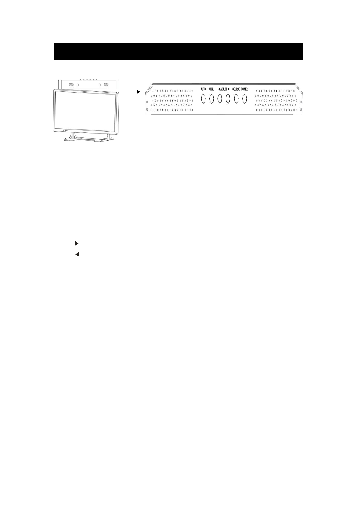
Touch Panel LCD: Key define
AUTO: Auto-optimize displaying picture under PC mode.
Enter: This “ Auto” Button can be either “Enter” function in OSD Menu)
MENU: OSD menu ON / OFF control.
(EXIT Item)
ADJUST: Increase or decrease the value on OSD menu.
Up: Increase value or turn ON / OFF function.
Down: Decrease value or turn ON / OFF function
SOURCE: Select input signal from AV1, AV2, S-Video or VGA (PC).
POWER: Monitor power ON / OFF. At OFF mode, monitor will be at standby status.
Green Light: ON Mode
Orange Light: Power Saving (Refer to note below)
Red Light: OFF Mode
Page 6

6
Touch Panel LCD: Connection define
1. VGA input
2. DVI input
3. PC audio in
4. VIDEO1
In: Video input
Out: Video loop output
S-VIDEO:Y/C input
Audio: Audio input
5. VIDEO2
In: Video input
Out: Video loop output
Audio: Audio input
6. Port 1 / Port 2 (Touch setting)
RS-485 connector
Single mode – PTZ to port 1 / DVR to port 2
Matrix mode – Matrix to port 2
7. RS-232
PC control interface
8. DC12V IN
Power input
Page 7
7
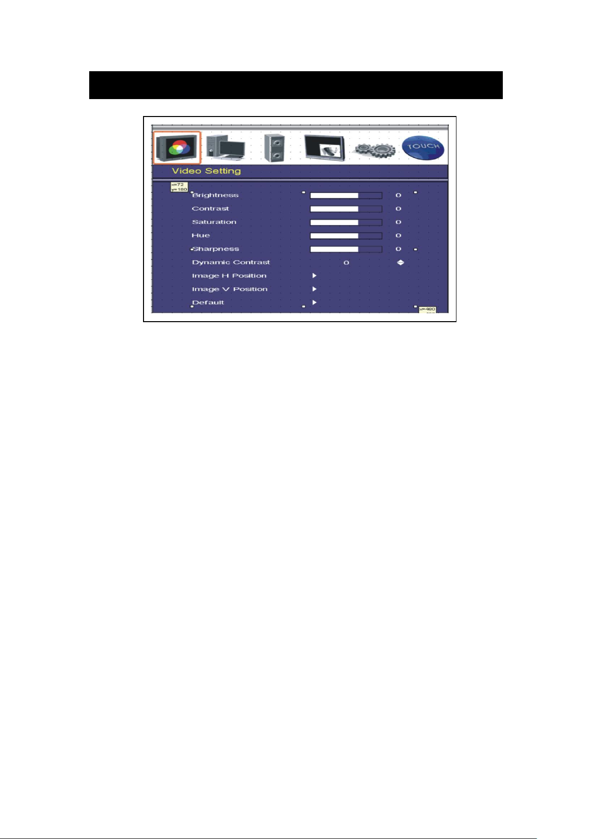
Touch Panel LCD: OSD-Video Setting
Brightness: Adjusts the overall picture shade and brightness.
Contrast: Permits adjustment of contrast between light and dark areas of the picture.
Saturation: Adjusts the intensity of the color.
Hue: To determine the lightness and colorfulness of the picture.
Sharpness: Sets the desired sharpening enhancement to the picture.
Dynamic Contrast: To determine the luminosity of motions of an object
Image H Position: Allows adjustment for horizontal position.
Image V Position: Allows adjustment for vertical position.
Default: Back to factory default
Page 8

8
Touch Panel LCD: OSD-DVI(VGA) Setting
Brightness: Adjusts the overall picture shade and brightness.
Contrast: Permits adjustment of contrast between light and dark areas of the picture.
Auto Adjustment: Picture adjustment automatic correction, like clock and phase.
Image H Position: Allows adjustment for horizontal position.
Image V Position: Allows adjustment for vertical position.
Phase: Is used to adjust best picture quality. It adjusts the sampling phase across one
pixel time. When the phase is not adjusted properly, the picture will be unclear.
Therefore this value should be carefully adjusted.
Note: improper adjustment will cause image failure.
Clock / Line: Is used to adjust best picture quality. It adjusts the numbers of the
pixel clock across one line time. Therefore it can affect the picture
position and size. Note: improper adjustment will caused image failure.
Default: Back to factory default
Page 9

9
Touch Panel LCD: OSD-Audio Setting
Volume: Controls built-in speakers’ output volumes.
Bass: Adjusts the tone to low frequency part of the sound.
Treble: Adjust the high or acute of the sound.
Balance: Adjusts the softness of loudness of notes in the sound.
Mute: To disable the audio function. To enable, press MUTE again.
Page 10

10
Touch Panel LCD: OSD-PIP Setting
PIP Mode: This function allows the PIP mode to be selected.
PIP Source: This function allows the source of the PIP to be selected.
PIP Swap: This function allows the position of PIP to be exchanged.
POP Zoom: Only Operate under POP (Side By Side) mode.
PIP Auto Close: Detect PIP mode signal.
PIP Switching: Enable PIP source switching.
Switching Time: Control PIP source switching time.
User H-Position: Allows adjustment for horizontal position.
User V-Position: Allows adjustment for vertical position.
Page 11

11
Touch Panel LCD: System Setting
Aspect Ratio: To change the display mode.
Auto Source Detection: The monitor will auto detect the video source when power ON.
Color Temperature: Selects color temperature of either 6500°K or 9300°K.
Channel Display: This function is to allow the channel title to be displayed on the
monitor.
Language: English.
Power On Control: This function is to assign a specific video signal when power
on.
Light Sensor: LCD monitor brightness will vary with the environment
brightness. LCD Brightness variation is from 3 lux to
0.5 lux(OFF)
Wake Up Time: When Light sensor set to ON, environment brightness is dark,
at same time panel becomes to OFF
Press front key as MENU / SOURCE / POWER to turn on
monitor. During 15 / 45 / 60 minutes, the light sensor detection
is temporarily off.
Page 12

12
Touch Panel LCD: OSD-Touch Setting
1
12
121
1218
success
Left Hander: Left hander mode control. Set to ON, left hander / Set to OFF, right hander
Touch Function Source: Touch mode under AV1 / AV2 / AV1:AV2. Select AV1:AV2, user can
touch the AV1 or AV 2 block icon to switch AV1 or AV2 source.
4:3 Mode: LCD display ratio always 4:3 and touch icon table is always on.
Number Page Transparency: 0 ~ 100
Control Mode: Single mode / Matrix mode select
Speed Dome protocol: Pelco-P / Pelco-D select. Depeands on
RS485 Port1 Baud Rate: 2400 / 4800 / 9600 select
RS485 Port2 Baud Rate: 2400 / 4800 / 9600 select
Buzzer Control: Warning buzzer on / off select
Pan / Tile Control Mode: Center mode: the cross symbol is always on the middle of screen
and it is the center point.
Finger mode: when the hand touches the LCD in the beginning, that
touch position is the center. The center position is released until
finger left.
Touch Panel Init: Touch screen initial
Password setting: Key lock password. All function key and panel can not operate.
Touch the panel, touch 1/2/1/8(default password) button and touch Enter to unlock.
Page 13

13
Control mode
P/T/Z Dome
Touch panel LCD
DVR Video
RS-485
Video
RS-485
Port 1
Port 2
Touch panel LCD
DVR Video
RS-485
Port 1
Touch panel LCD
Video
RS-485
Port 2
P/T/Z Dome
AV1
AV2
AV1
AV2
SINGLE mode: Only one control keyboard in the system. Single mode can be includes these
systems below.
System A:
System B:
System C:
RS-485(RJ-11) pin define: 3 + / 4 -
Page 14

14
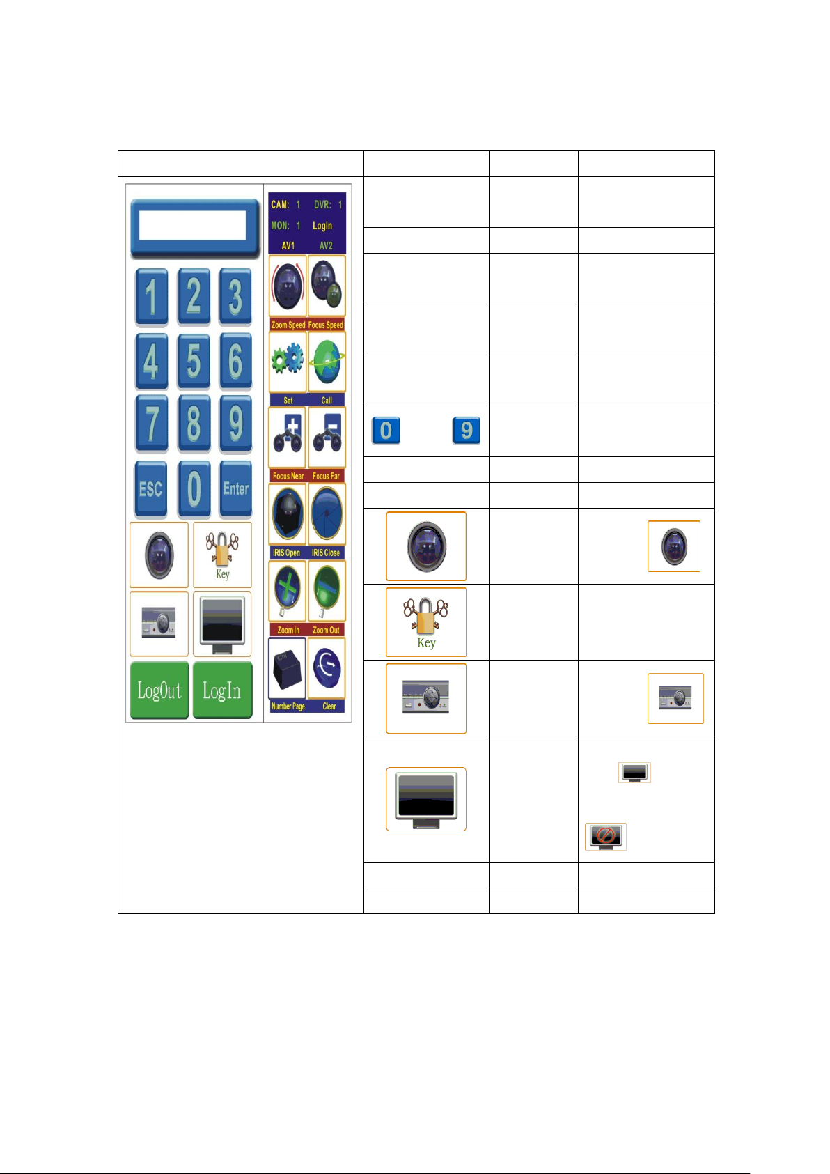
PTZ control mode - Single mode
Touch Icon
Icon
Mode
Notice
CAM: 000
Camera ID
Call camera ID status
DVR: 000
DVR ID
Call DVR ID status
MON: 000
Monitor ID
Call monitor ID status
AV 1
Channel 1
Video 1 input source display
AV 2
Channel 2
Video 2 input source display
Zoom Speed
Speed control
1 ~ 4 + Zoom Speed
Focus Speed
Speed control
1 ~ 4 + Focus Speed
Set
ID + Set
Set the PTZ preset
Call
ID + Call
Call the PTZ preset
Focus Near
Manual
Focus Near
Only manual mode
Focus Far
Manual
Focus Far
Only manual mode
IRIS Open
Manual
IRIS Open
Only manual mode
IRIS Close
Manual
IRIS Close
Only manual mode
Zoom In
Lens Zoom in
PTZ camera zoom in
Zoom Out
Lens Zoom Out
PTZ camera zoom out
Number Page
ID table
Device and ID table
Clear
Clear preset
Presets clear
1. Touch any position on the panel
2. Touch number page button into number table
3. Select PTZ(CAM) ID and call PTZ(CAM), ex:
+
Main control
Page 15
15
PTZ control with number table
Touch Icon
Icon
Mode
Notice
CAM: 000
Camera ID
Call camera ID
status
DVR: 000
DVR ID
Call DVR ID status
MON: 000
Monitor ID
Call monitor ID
status
AV 1
Channel 1
Video 1 input
source display
AV 2
Channel 2
Video 2 input
source display
~
ID(number)
ID + Set / ID + Call
ID + Clear
ESC
Cancel
ID cancel
Enter
Confirm
ID confirm
Call PTZ /
Camera
Key lock
protection
Touch key button
count to 3 seconds
to key lock mode
Call
DVR
Call
Monitor
Only Matrix mode
ID +
Single mode with
LogOut
Log out
Only Matrix mode
LogIn
Log in
Only Matrix mode
ID +
ID +
Notice:
The touch and key lock table would disappear after 10 seconds if no any operation.
Page 16

16
PTZ Preset Function ID corresponding table
Preset ID
ID + Call
ID + Set count to 3 seconds
33
180 degree rotating
34
Speed dome return to zero
76
Start auto pan
92
Set line scan left stop
93
Set line scan right stop
95
Speed dome OSD Menu
96
Stop line scan
99
Start line scan
Pan / Tile Control Mode: Center / Finger.
Center mode: the cross symbol is always on the middle of screen and it is the center point
Finger mode: when the hand touches the LCD in the beginning, that touch position is the
center. The center position is released until finger left.
Preset ID + Set button (count to 3 seconds) = Set Preset Function
Preset ID + Call button = Call Preset Function
Preset ID + Clear button to delete preset one by one
Touch the Clear button (count to 3 seconds) to delete all presets
Touch the panel to move item or change value when PTZ OSD on
Touch the IRIS Open button into main or sub menu
Touch the panel to move item to EXIT and then touch the IRIS Open button to quit OSD
Page 17

17
DVR control mode - Single mode
Touch Table
Icon
Mode
Notice
CAM: 000
Camera ID
Call camera ID status
DVR: 000
DVR ID
Call DVR ID status
MON: 000
Monitor ID
Call monitor ID status
AV 1
Channel 1
Video 1 input source display
AV 2
Channel 2
Video 2 input source display
Sequence
Channel Sequence
DVR Channel Sequence function
Zoom/Enter
Digital zoom / Enter
DVR image x2 zoom / Enter fun.
Ch. Sel
Channel Selection
DVR Channel Selection
Freeze
Image freeze
DVR image freeze
Search
Time search page
DVR time search mode
Dome Ctrl
DVR Dome Control
DVR Dome Control mode
Play/Stop
Playback start/stop
DVR Playback start/stop mode
Mode
4/9/16 split switch
DVR monitor out on 4/9/16 split
Extension Page
Second page
DVR sub function control
ESC
Escape Menu fun.
DVR Menu escape function
Number Page
ID table
Device and ID table
Key Lock
DVR Key Lock
DVR Command Key Lock mode
1. Touch any position on the panel
2. Touch number page button into number table
3. Select DVR ID and call DVR, ex:
+
Main control - Normal page
Notice:
The touch and key lock table would disappear after 10 seconds if no any operation.
Page 18
18
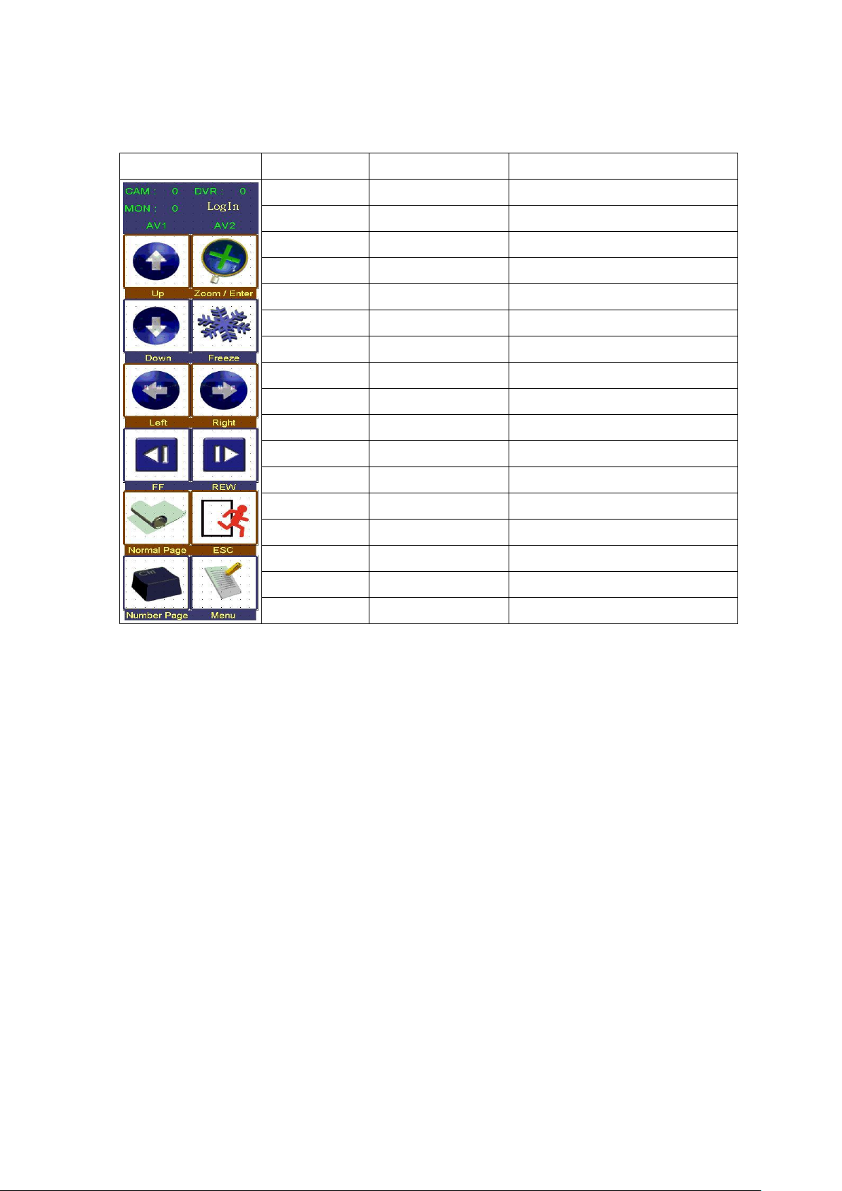
Extension page
Touch Icon
Icon
Mode
Notice
CAM: 000
Camera ID
Call camera ID status
DVR: 000
DVR ID
Call DVR ID status
MON: 000
Monitor ID
Call monitor ID status
AV 1
Channel 1
Video 1 input source display
AV 2
Channel 2
Video 2 input source display
Up
Direction button
DVR OSD item select
Zoom/Enter
Digital zoom / Enter
DVR image x2 zoom / Enter fun.
Down
Direction button
DVR OSD item select
Freeze
Image freeze
DVR image freeze
Left
Direction button
DVR OSD item select
Right
Direction button
DVR OSD item select
FF
Fast Forward
1~32X speed set of FF function
REW
Rewind
1~32X speed set of REW function
Normal Page
First page
DVR main function control
ESC
Escape Menu fun.
DVR Menu escape function
Number Page
ID table
Device and ID table
Menu
Call menu
Call/quit DVR OSD
Notice:
The touch and key lock table would disappear after 10 seconds if no any operation.
Page 19

19
DVR control with number table
Touch Icon
Icon
Mode
Notice
CAM: 000
Camera ID
Call camera ID
status
DVR: 000
DVR ID
Call DVR ID status
MON: 000
Monitor ID
Call monitor ID
status
AV 1
Channel 1
Video 1 input
source display
AV 2
Channel 2
Video 2 input
source display
~
ID(number)
ID + Full button to
DVR full screen
ESC
Cancel
ID cancel
Enter
Confirm
ID confirm
Call PTZ /
Camera
Key lock
protection
Touch key button
count to 3 seconds
to key lock mode
Call
DVR
Call Monitor
Only Matrix mode
ID +
Single mode with
LogOut
Log out
Only Matrix mode
LogIn
Log in
Only Matrix mode
ID +
ID +
Notice:
The touch and key lock table would disappear after 10 seconds if no any operation.
Page 20

20
 Loading...