

Page 1

Speco Internet Protocol (SIP)H.264
Series Camera Instruction Manual
(Version 1.0.0)
SIP H.264 Megapixel Cameras
SIPMPBVFH & SIPMPDVFH
Speco Technologies
i
200 New Hwy, Amityville, NY 11701
800-645-5516 www.specotech.com
Page 2

Table of Contents
1. FEATURES ....................................................................................................... 1-1
1.1 Package ..................................................................................................................... 1-1
1.2 Dimension and Connector Description
1.2.1 Dimensions .................................................................................................................... 1-2
1.2.2 Connector Description ................................................................................................... 1-4
..................................................................... 1-2
2. INSTALLATION .............................................................................................. 2-5
2.1 Recommended PC Specification ............................................................................ 2-5
2.2 Preparation before setup ........................................................................................ 2-6
2.2.1 Setup your PC network .................................................................................................. 2-6
2.3 Configuring the IP device ................................................................................. 2-11
2.3.1 Video Display .............................................................................................................. 2-13
2.3.2 Date & Time ................................................................................................................ 2-16
2.3.3 Network Section .......................................................................................................... 2-18
Host .......................................................................................................................................... 2-19
IP Address Filtering ................................................................................................................. 2-20
Port Mapping ........................................................................................................................... 2-22
ToS ........................................................................................................................................... 2-24
UPnPTM .................................................................................................................................... 2-25
SNMP Setting .......................................................................................................................... 2-26
RTP .......................................................................................................................................... 2-26
Speed & Duplex ....................................................................................................................... 2-28
2.3.4 IP Settings .................................................................................................................... 2-29
Connection Type ...................................................................................................................... 2-29
DNS ......................................................................................................................................... 2-31
DDNS ...................................................................................................................................... 2-32
2.3.5 Video & Audio ............................................................................................................ 2-33
Video ........................................................................................................................................ 2-33
2.3.6 System ......................................................................................................................... 2-51
User Account ........................................................................................................................... 2-51
System Info .............................................................................................................................. 2-52
Factory Default ........................................................................................................................ 2-53
Firmware Upload ..................................................................................................................... 2-54
ii
Page 3

Profile Upload .......................................................................................................................... 2-55
Save & Reboot ......................................................................................................................... 2-56
Logout ...................................................................................................................................... 2-56
APPENDIX .............................................................................................................................. 2-57
3.1 Specification ........................................................................................................... 2-57
3.1.1 SIP H.264Camera Series ............................................................................................. 2-57
iii
Page 4

Page 5
1
Cross LAN Cable
1. FEATURES
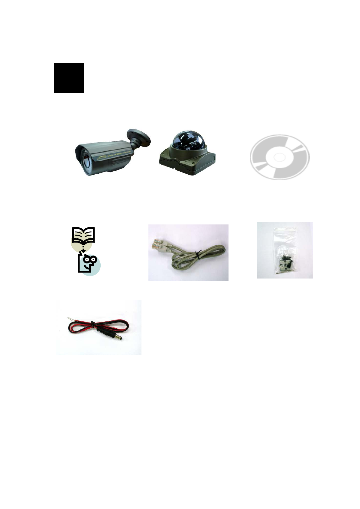
1.1 Package
SIPMPBVFH Camera
Quick Install Guide
Power Lead Cable
SIPMPDVFH Camera
Software CD
Accessory Pack
Package of Products is composed of the main body of the camera, Software CD (NVR
Program, Product Manual, NVR Manual), Quick Install Guide, Cross LAN Cable,
Accessory Pack, Power Lead Cable.
Please check before starting installation.
1-1
Page 6
1.2 Dimension and Connector Description
1.2.1 Dimensions
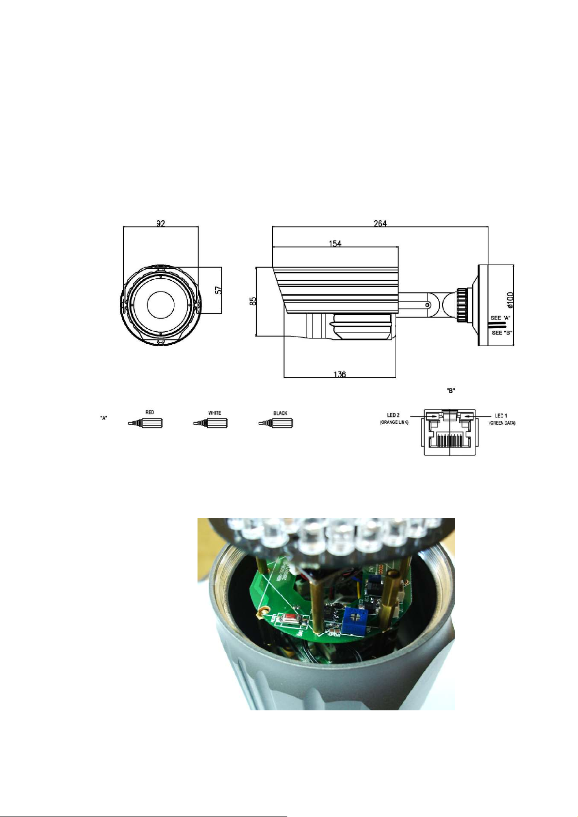
1. SIPMPBVFH
①
②
③
⑤
④
⑥
1-2
Page 7
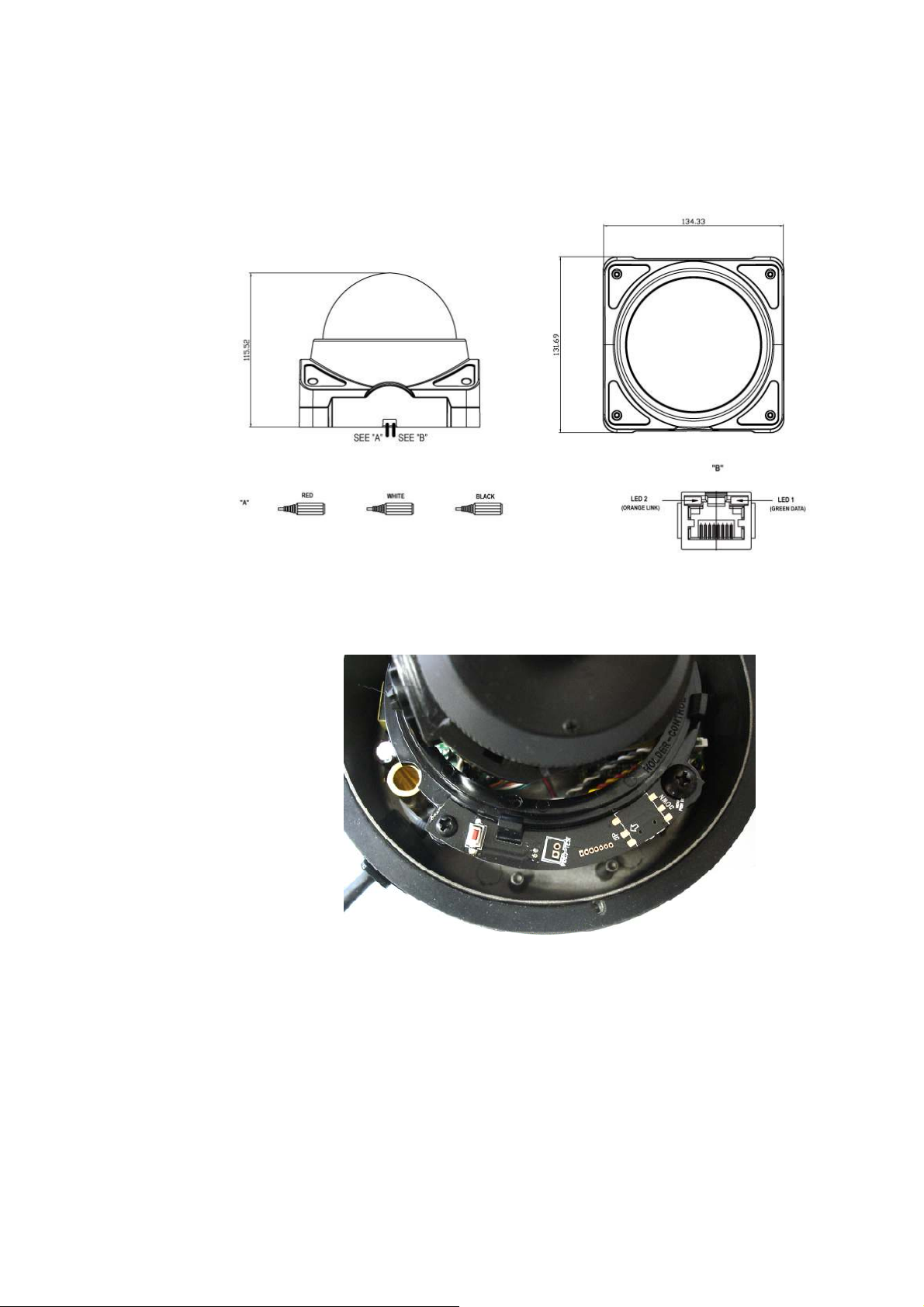
2. SIPMPDVFH
①
②
③
④
⑤
1-3
Page 8

1.2.2 Connector Description
① 12 Volts DC Power Input
② Audio Output
③ Audio Input : The SIP Camera supports one audio input and output
④ Ethernet Port : Standard RJ45 connector. Supporting POE.
⑤ Reset Button (** Please open the case for the Bullet / Dome type camera )
Step 1 : Switch off SIP Camera by disconnecting the power cable.
Step 2 : Using a suitable pointed object, press and continue to hold the Reset
Button. While continuing to hold the reset button, reconnect the power cable.
Step 3 : Keep holding the reset button for 6 seconds, release the reset button.
The unit will start up with factory default settings.
⑥ LED Light level controller
1-4
Page 9

2
2. INSTALLATION
2.1 Recommended PC Specification
CPU
Memory
Operating System
Video Resolution
CPU
Core2Duo 2.13GHz and above
2 GB or above
Windows XP with SP2 or above. Windows Vista / Windows 2003 /
Windows 7
Internet Explorer 6.0 SP2 and above.
SVGA or XGA with 1024x768 resolution
Core2Duo 2.13GHz and above
2-5
Page 10

2.2 Preparation before setup
To configure your IP device, you have to use Internet Explorer to log in.
Before that, your PC’s network settings and the IP device’s IP address must
be set up. Make sure all the connections are connected correctly, and then
follow the procedures below.
1. Setup your PC network
You have to match your PC’s TCP/IP setting with the IP device’s
default settings before you can use IE browser to login it. This section
tells you how to setup your PC’s TCP/IP settings.
2. Setup IP device’s IP address
This IP device’s IP address can be setup manually or automatically by
network service (DHCP). If it acquires the IP address by using the
DHCP service, please use the IP utility software bundled in the product
CD to search all the IP devices’ IP address.
2.2.1 Setup your PC network
To set up the network of IP device via a PC, you have to change the TCP/IP
settings of the PC.
The following are the default network settings of IP device.
IP Address: 192.168.0.100
Subnet Mask: 255.255.255.0
To access the IP device, the IP address of the PC should match the address
below.
IP Address: 192.168.0.xxx
Subnet Mask: 255.255.255.0
NOTE: xxx should be a number from 1 to 254, but 100 is excepted.
2-6
Page 11
The procedure below is the setup procedure of a PC using Windows XP as
its OS. When running an OS other than Windows XP, please refer to the
manual included with the OS.
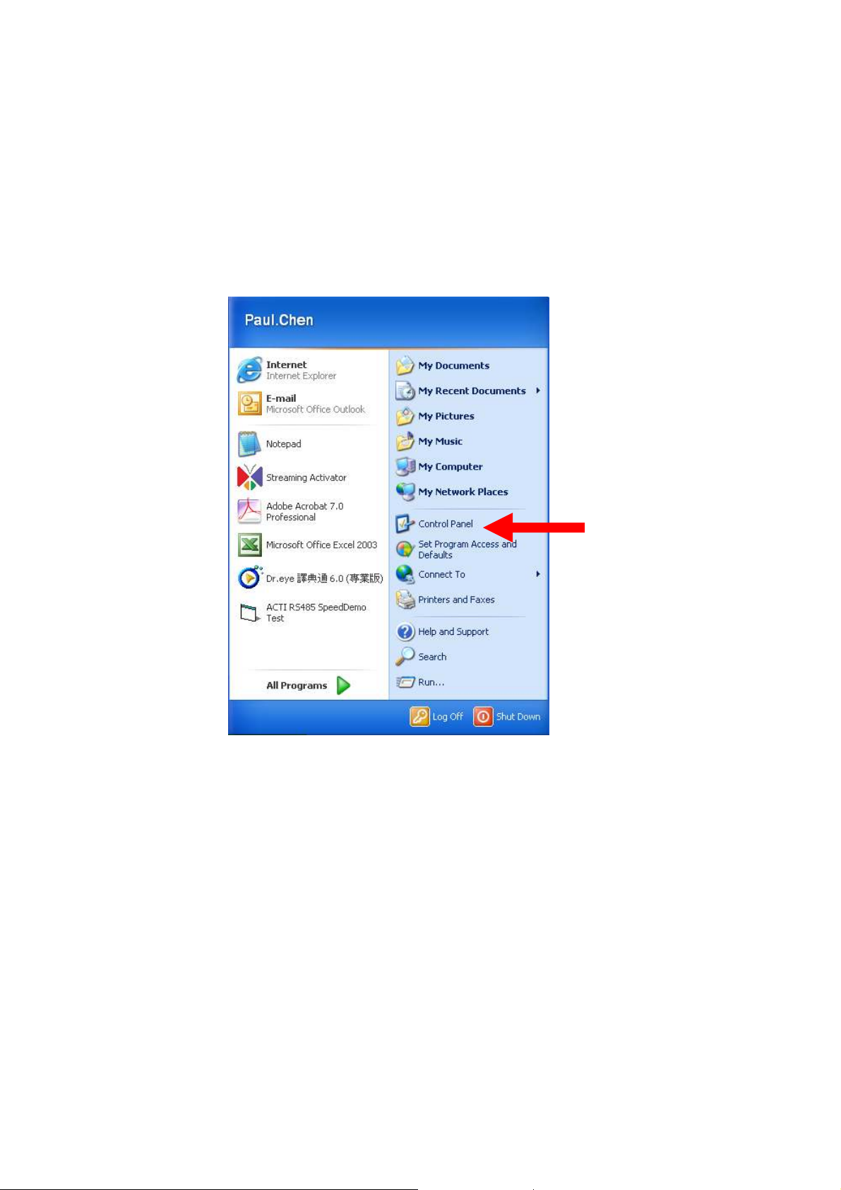
STEP 1
Start up your PC.
STEP 2
Click the [Start] and select the "Control Panel"
2-7
Page 12
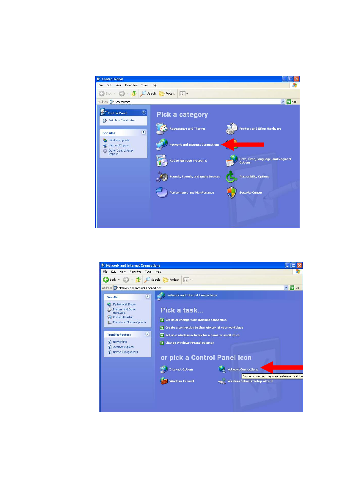
STEP 3
Double-click the "Network and Internet connections" icon.
STEP 4
Double-click the "Network connections" icon
2-8
Page 13
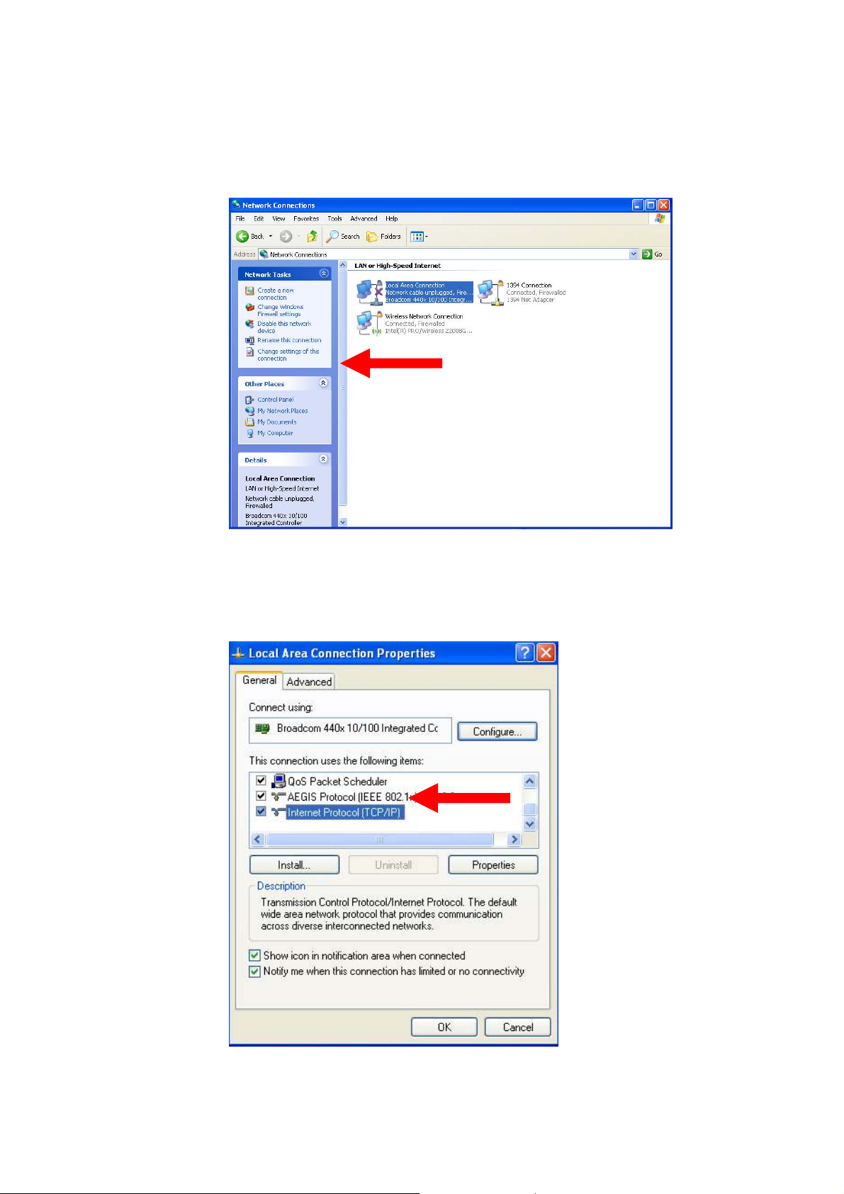
STEP 5
Click “Local Area Connections”, and then click “Change settings of
this connection” in the network Task menu.
STEP 6
Click “Internet Protocol (TCP/IP)”, and then click the [Properties]
button.
2-9
Page 14
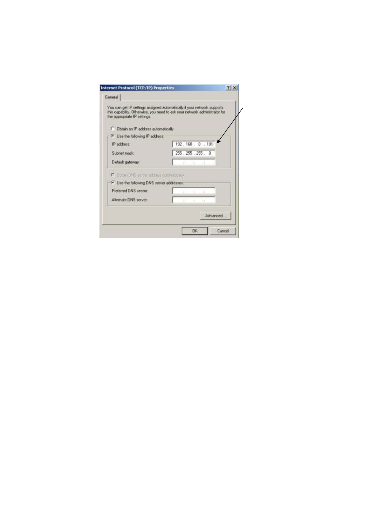
STEP 7
Click the “Use the following IP address” radio button and enter the IP
address and the subnet mask.
Please set the settings as below.
IP address: 192.168. 0.xxx
Subnet mask: 255.255.255. 0
(NOTE: xxx should be a number
from 1 to 254, but 100 is
excepted.)
STEP 8
Click the [OK] button and the window dialog box closes.
2-10
Page 15
2.3 Configuring the IP device
This section describes how to configure the IP device. The product
administrator has unlimited access to all setup windows and normal users
can only watch the live image. The IP device is configured under a
standard browser (Microsoft Internet Explorer 6.0 or above).
Follow the procedures below to configure the IP device.
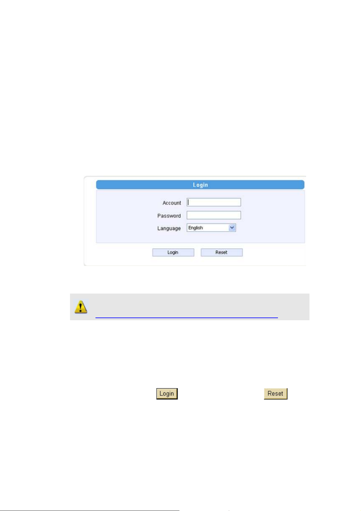
STEP 1: Open a browser
STEP 2: Enter the IP address of the IP device.
The default IP address is “192.168.0.100”
The “Login Page” is now displayed as below.
STEP 3: Enter the Account name (factory default: Admin) and the
Password (factory default: 123456).
NOTE: Internet Explorer of 6.0 or above is highly recommended. If you
don’t have the it, please download it from
http://www.microsoft.com/windows/ie/downloads/default.mspx
STEP 4: Select the language of the IP device user interface. You can
select from English, Traditional Chinese, Simplified Chinese, Japanese,
Spanish, Italian, German, Portuguese, Czech and French. This user
interface setting will disappear once you log out, if you want to change
the default user interface language, please change the setting of [Host
setting] after login success.
STEP 5: Click the
button to login or click the button
to re-enter again.
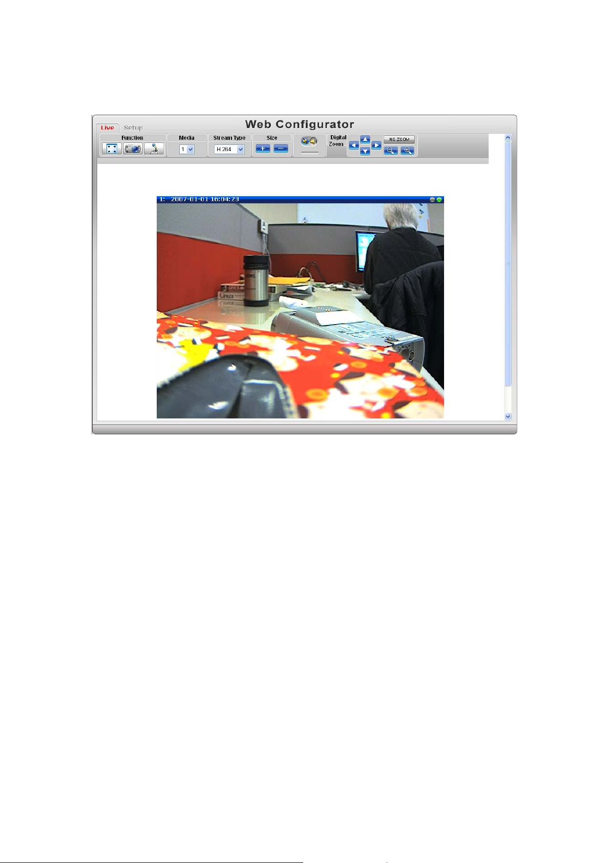
Once successfully login, the “Video Display page” will be displayed
as below.
2-11
Page 16
2-12
Page 17
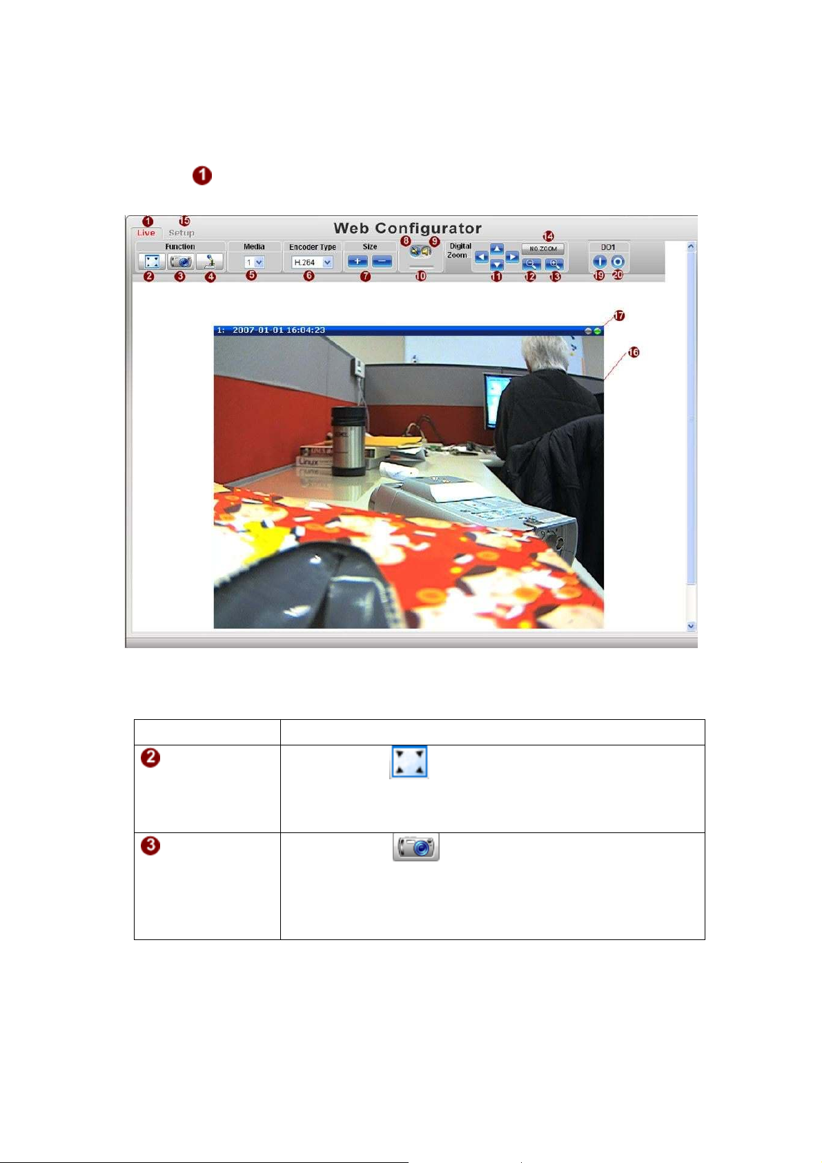
2.3.1 Video Display
This section tells you how to view live images via Internet Explorer.
Click the
[Live] tab to show [Live page]. Refer to the table below for how to
configure each setting.
Function List
Function Description
Full Screen
Click the icon
You can click “Esc” button on the keyboard to return to
previous display.
Snapshot
Click the icon “
picture will be saved to the default folder
“C:\Users\”account name”\Picture”, in the format of
YYYYMMDD_HH_mm_ss.jpg.
2-13
to stretch the preview to full screen.
” to take a snapshot. The snapshot
Page 18
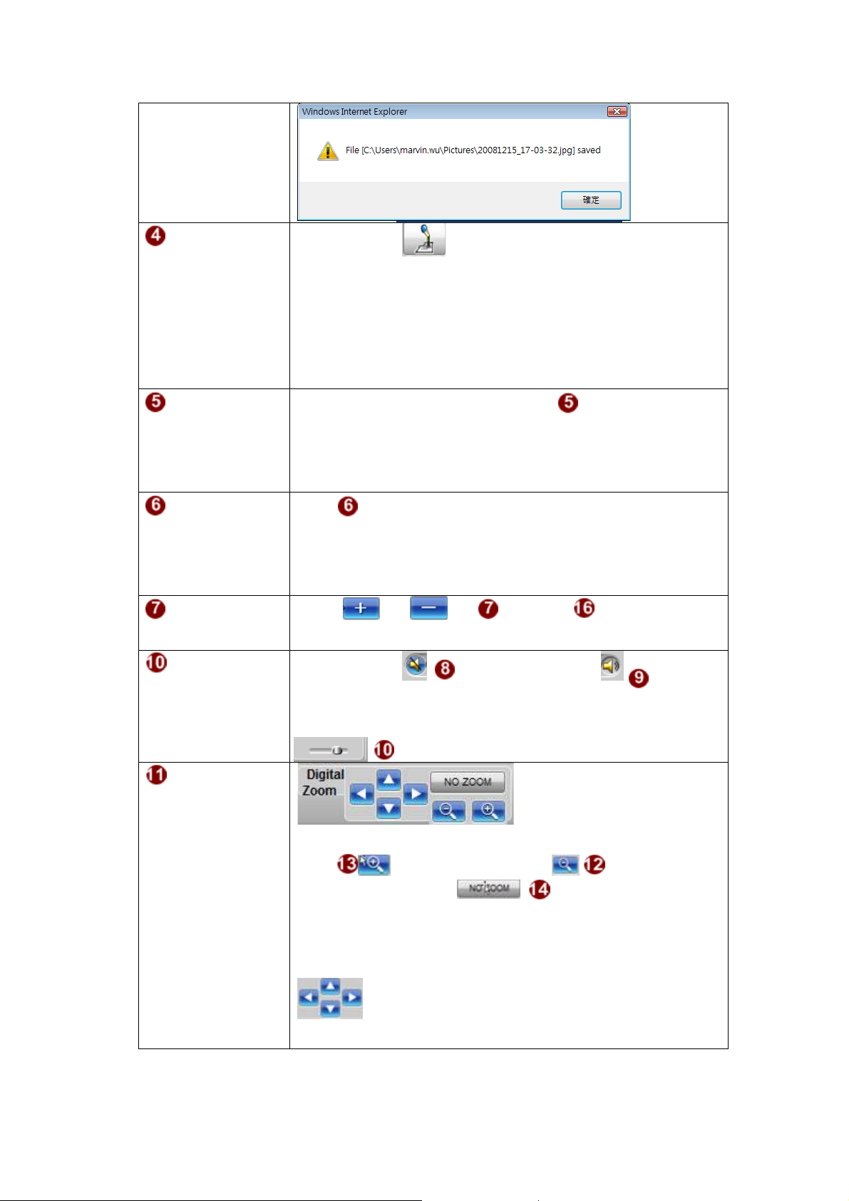
Audio out
Click the icon
to enable the audio out from PC to IP
camera or video server. When it is enabled, your voice will
be transferred to the audio out of the IP camera or video
server.
NOTE: you will need to have a microphone connected to
your PC to do that.
Media
If dual stream mode is enabled, click to select which
stream to display (Media 1 or 2). The default is single stream
only. To change to dual stream mode, please refer to “Media
1” section under “Setup” tab
Encoder Type
Click to select the compression codec used in video
encoding. The Encoder type option includes MPEG-4,
MJPEG and H.264. Once selected, the video server/IP
camera will start to send video in new stream type.
Display size Click or of to adjust display screen
size
Audio in
Click the icon
to mute or the icon to
receive audio in from the video server/IP camera. Drag the
volume bar
to adjust the volume.
Digital Zoom
Digital zoom enables you to zoom into the image. You can
click to zoom in and click to zoom
out. You can click the “no zoom” button
to cancel all zoom-in and go back to original status (no zoom
status).
When you digitally zoom in the video, you can click
to pan/tilt the video up, down, left and right.
NOTE: This pan/tilt function does not work if the video is
2-14
Page 19
not zoomed-in (no zoom status).
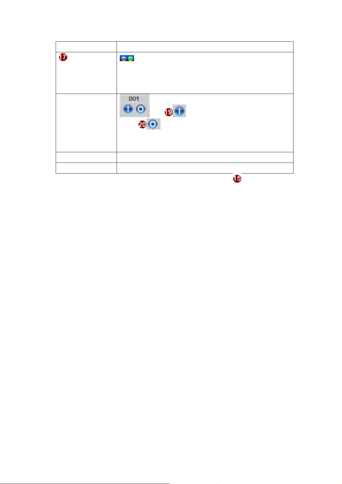
Network
status
Indicates the network state. If the light on the right is
green, it means the network is ok. If the light is gray, it
means the network is broken.
The light on the left is not used
DO Setting
Click to set DO output level to High.
Click
to set DO output level to Low. If your device
has more than one DO available, each DO is controlled
separately.
If you want to setup this IP camera/video server, please click the [Setup] tab to
switch to “Setup Page”
2-15
Page 20
2.3.2 Date & Time
enables
to synchronize its time settings with a SNTP/NTP
l your IP devices’
time is the same. Additionally, with our embedded
code in the streaming, you can tell the event sequence
or this IP device to
This section tells you how to setup IP device’s date and time settings.
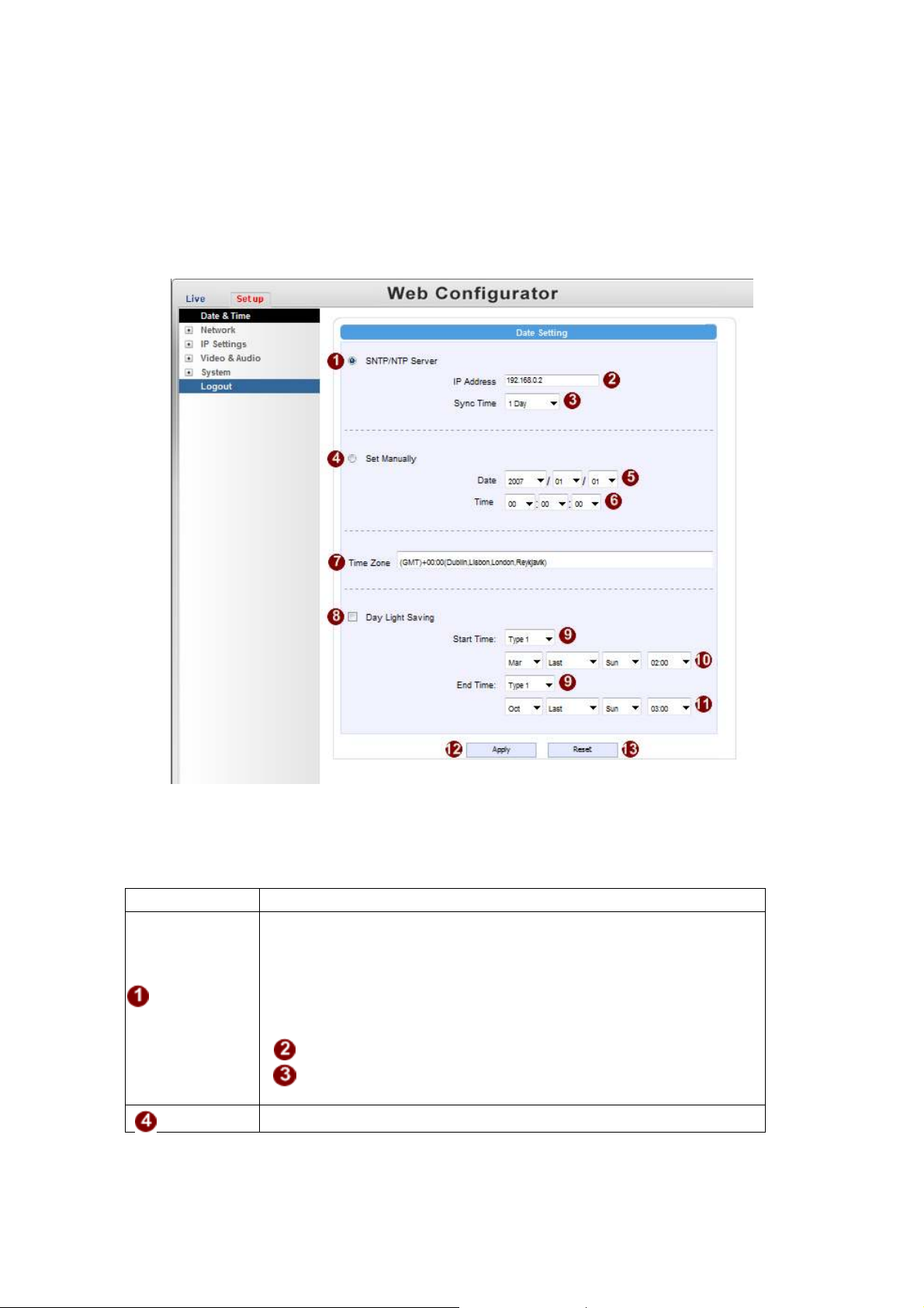
STEP 1: Click the [Date & Time] on the “Main Setup page”.
The “Date setting page” is displayed as below
STEP 2: Configure these settings with reference to the table below. If you
are still unsure what to set, contact your system administrator.
Date Setting
Parameters Description
Click this to enable IP device’s SNTP/NTP function. This
this IP device
server. You can use this function to make sure al
SNTP/NTP
server
Set
2-16
digital-timeaccurately.
IP address: Enter the IP address of the SNTP/NTP server.
Sync time: Select the time interval f
synchronize its time.
Click this to manually setup the date & time.
Page 21

manually
Date
to specify daylight saving time by week
daylight saving time
: Select the date
Time: Select the time
Time zone
Select the time zone offset for local settings
Select Type 1
number in a month; select Type 2 to specify
Day Light
Saving
by date.
Start Time: Select the daylight savings start time.
End Time: Select the daylight savings end time.
Click the [Apply] button to confirm the settings or click the [Reset] button to
re-enter the parameters.
2-17
Page 22

2.3.3 Network Section
Click the
[Network] item on the “Setup Page”.
2-18
Page 23

Host
Click the [Host] to enter Host settings page. Refer to the table below for how to configure
each setting.
Parameters
Enter a host name, and this host name will be shown when
Host name
Language
Camera name
Click the [Apply] button to confirm the settings or click the [Reset] button to
re-enter the parameters.
you use the IP utility or the SDK to search for the IP
device.
Select the language of default user-interface. Each user
login will see the default user-interface first.
The camera name is reserved for customer use.
Description
2-19
Page 24

IP Address Filtering
WARNING: Please be very careful when using this function, as you may
lose access to your camera if you make mistakes in setup. You may either
accidentally deny yourself access, or forgot to include your own IP address
in the allowed address list. You will need to perform hard reset to be able to
Click the [IP Address Filter] item to display the “IP Address Filtering Page”. Refer to the
table below for how to configure each setting.
2-20
Page 25

address per
uture use. If a
Parameters Description
IP address
filter enable
Filter
Method
IP Address
Netmask
Check this box to enable IP Address Filtering.
The filter can be set in either “Allow” mode or “Block” mode.
1. “Allow” mode will refuse access to all IP addresses except the
ones listed below.
2. “Block” mode will accept all incoming access except the IP
addresses listed below.
Make sure you include the Netmask in your consideration.
The IP address you wish to allow or block. Please note that the
actual range is modified by the Netmask.
Using Netmask allows you to set filtering for a whole range of IP
address at once, without the need to enter all of them individually.
If you are not sure about the function of netmask, then you should
use 255.255.255.255, and it will affect only a single IP
line of entry, or use 255.255.255.0 to use the same setting for all
IP addresses starting with the same three numbers. .
For each entry, you must check this box for it to be effective. For
an entry that you no longer need but does not wish to delete, you
Enable
can uncheck it, and the system will remember it for f
new entry that has never been used before does not have Enable
checked, then it will not be stored in memory.
Click this to use the current displayed info to do IP Address
Apply
filtering. If you setup correctly, it will change into a grayed out
“Success” in a few seconds.
Reset Click this button to re-enter the parameters.
Click the [Apply] button to confirm the settings or click the [Reset] button to
re-enter the parameters.
2-21
Page 26

Port Mapping
Click the [Port Mapping] item to display the “Port Mapping Page”. Refer to the table
below for how to configure each setting.
Parameters Description
HTTP port
HTTPS
Search server port1
Search server port2
Video control port
2-22
Select the port assigned for HTTP protocol access
Select the port assigned for HTTPS protocol access
Select the first port used by server search applications to
detect this IP device. (e.g. IP utility)
Select the first port used by server search applications to
detect this IP device. (e.g. IP utility)
Select the port used to support video control function by
application programs. (e.g. NVR)
Page 27

Video streaming
port (TCP Only)
Video Multicast
Port
RTSP port
RTP Multicast
Video Port for
Media1
RTP Multicast
Audio Port for
Media1
RTP Multicast
Video Port for
Media2
RTP Multicast
Audio Port for
Media2
Select the port used by this IP device for Video
Streaming.
Enable/disable multicast audio streaming
Select the port assigned for RTSP protocol access
Select the port for the multicast video streaming of
media1 via RTP protocol
Select the port for the multicast audio streaming of
media1 via RTP protocol
Select the port for the multicast video streaming of
media2 via RTP protocol
Select the port for the multicast audio streaming of
media2 via RTP protocol
Multicast IP Select the multicast IP. Default settings is 228.5.6.1
Multicast TTL Select the multicast TTL. Default setting is 255.
Select video type connected to the video-in of this IP
IGMP
device. If you use an incorrect video type, some images
might be lost.
Click the [Apply] button to confirm the settings or click the [Reset] button to
re-enter the parameters.
2-23
Page 28

ToS
Click the [ToS] (Type of Service) item to display the “ToS Page”. Refer to the table
below for how to configure each setting.
Parameters Description
TOS (type of
service)
TOS priority
Select whether to add the TOS tag onto the streaming data.
Streaming data with a higher priority TOS tag will be
transmitted first when compared with other data.
Select the TOS tag’s priority to be added onto the
streaming. You can select between
1.Minimize-Delay
2.Maximize-throughout
3.Maximize-Reliability
4.Normal-Service
Click the [Apply] button to confirm the settings or click the [Reset] button to
re-enter the parameters.
2-24
Page 29

UPnP
TM
Click the [UPnPTM] item to display the “UPnPTM Setting Page”.
Click checkbox to enable or disable the UPnPTM function. Edit the UPnP Friendly
Name in text field.
Click the [Apply] button to confirm the settings or click the [Reset] button to
re-enter the parameters.
2-25
Page 30

SNMP Setting
Click the SNMP Setting item to display the SNMP setting Page
Click
Select
Check the check box
Enter the Destination IP address in
Enter the Trap Community used in
Select the Available trap in
Click the [Apply] button
to re-enter the parameters.
to enable SNMP function.
to use SNMP V1/V2 or to use SNMP V3
to enable traps
to confirm the settings or click the [Reset] button
RTP
Click RTP Item to configure RTP Settings
2-26
Page 31

RTSP Authen
Enable
RTP B2 Frame
Enable
Check box to enable RTP streaming’s Account/Password
authentication.
Check box to enable the B2 frame in RTP streaming
Click the [Apply] button
re-enter the parameters.
to confirm the settings or click the [Reset] button to
2-27
Page 32

Speed & Duplex
This item lets you select the network transmission speed.
Click the [Speed & Duplex] item in the network section to display the ”Speed and
Duplex” Page. Refer to the table below for how to configure each setting.
Parameters Description
You can select from
Network
speed
1. Auto detect (default setting)
2. 100Mbps / Full duplex
3. 100Mbps / Half duplex
4. 10Mbps / Full duplex
5. 10Mbps / Half duplex
Click the [Apply] button to confirm the settings or click the [Reset] button to
re-enter the parameters.
2-28
Page 33

2.3.4 IP Settings
Connection Type
Click the [Connection Type] item to display the “Connection Type Page”. Refer to the
table below for how to configure each setting.
Parameters Description
Click this to enable IP device’s DHCP function.
Dynamic IP
address
Static IP
address
PPPoE
It will acquire its WAN port IP address from a DHCP server
within the same network. (You must have a DHCP server in
order to enable this function.)
Click this to manually enter the IP address.
IP address: Enter the WAN port IP address.
Subnet mask: Enter the subnet mask of WAN port. If IP
address is changed, adjust the subnet mask
accordingly.
ISP gateway: Enter the IP address of the gateway (the
router).
Click this when you connect IP device directly to the xDSL
modem.
User name: Enter the user name of your xDSL account.
Password: Enter the password of your xDSL account.
Note: You have to click the [Save Reboot] after you click the
[Apply button] to let this IP device start xDSL connections.
2-29
Page 34

IPV6
Click the check box to support IPV6 protocol
Click the [Apply] button to confirm the settings or click the [Reset] button to
re-enter the parameters.
2-30
Page 35

DNS
Click the [DNS] item to display the “DNS Server Settings Page”. Refer to the table
below for how to configure each setting.
Parameters Description
Defines the IP address of the primary DNS server. This is
Primary DNS server
Secondary DNS
server
Click the [Apply] button to confirm the settings or click the [Reset] button to
re-enter the parameters.
used for identifying this computer by name instead of IP
address.
The IP address of the secondary DNS server. It will be used
once the primary DNS server fails.
2-31
Page 36

DDNS
DDNS function enables user to connect to this IP device by domain
a DDNS service account for this
Enter the host name of your DDNS service account. (ex:
Click the [DDNS] item to display the “DDNS Server Setting Page”. Refer to the table
below for how to configure each setting.
Parameters Description
Click this to enable IP device’s DDNS function.
DDNS type
name even if its IP address is not static.
Protocol /
Service
Reference
Host name
User name
Password
Click the [Apply] button to confirm the settings or click the [Reset] button to
re-enter the parameters.
Click one of the DDNS service providers.
You can visit their website to get
IP device.
xxxx.dyndns.org)
Enter the user name to login your DDNS service account.
Enter the password to login your DDNS service account.
2-32
Page 37
2.3.5 Video & Audio
Click the
Please note that some elements may not appear on all models.
[Video & Audio] item on the “Setup Page”.
Video
Click the [Video] item to display the “Video Page”. The functions here are grouped
under different tabs. Starting from firmware version 4.07, there are two sets of all settings
in the Video section, one for day time and one for nighttime. The camera will
automatically load different profile based upon the current Day/Night status. This
function allows for tailored configuration so that the camera may perform optimally
under all lighting conditions.
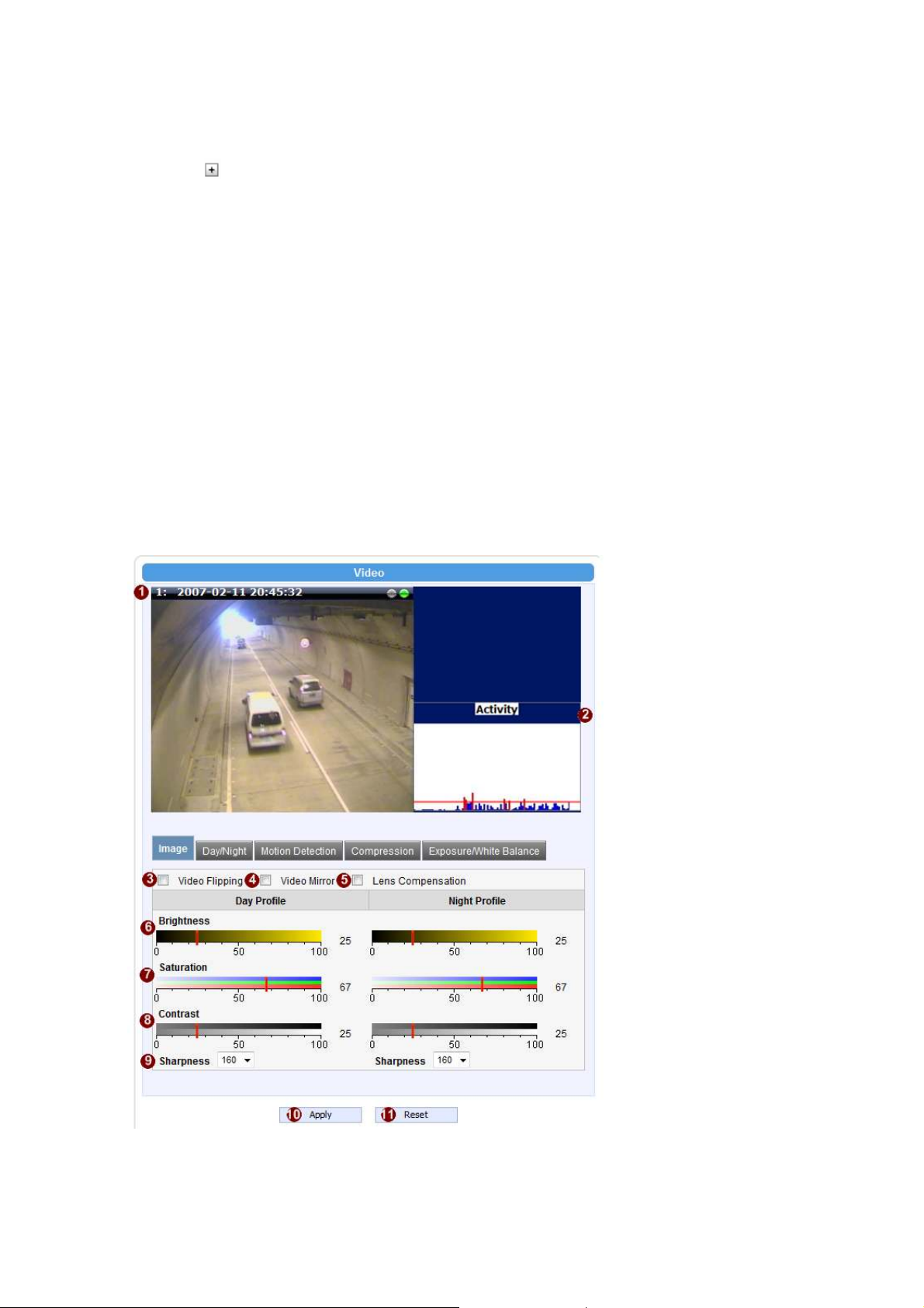
Image (CMOS Models)
This tab concerns the general video settings. Please refer to the table below for functions.
2-33
Page 38

Parameters Description
Live View
Activity
Video Flipping
Video Mirror
Lens Compensation
Brightness
(Day Profile)
Saturation
(Day Profile)
Contrast
(Day Profile)
Brightness
(Night Profile)
Saturation
(Night Profile)
Contrast
(Night Profile)
Sharpness
(Day Profile))
Sharpness
(Night Profile)
Live view of the camera
Motion activity status
Check this box to flip the video up-down
Check this box to mirror the video left-right
Check this box to use best pre-set settings for
bundled lens
Select the brightness value
Select the saturation value
Select the contrast value
Select the brightness value
Select the saturation value
Select the contrast value
Select the sharpness value
Select the sharpness value
Click the [Apply] button to confirm the settings or click the [Reset] button to
re-enter the parameters.
2-34
Page 39
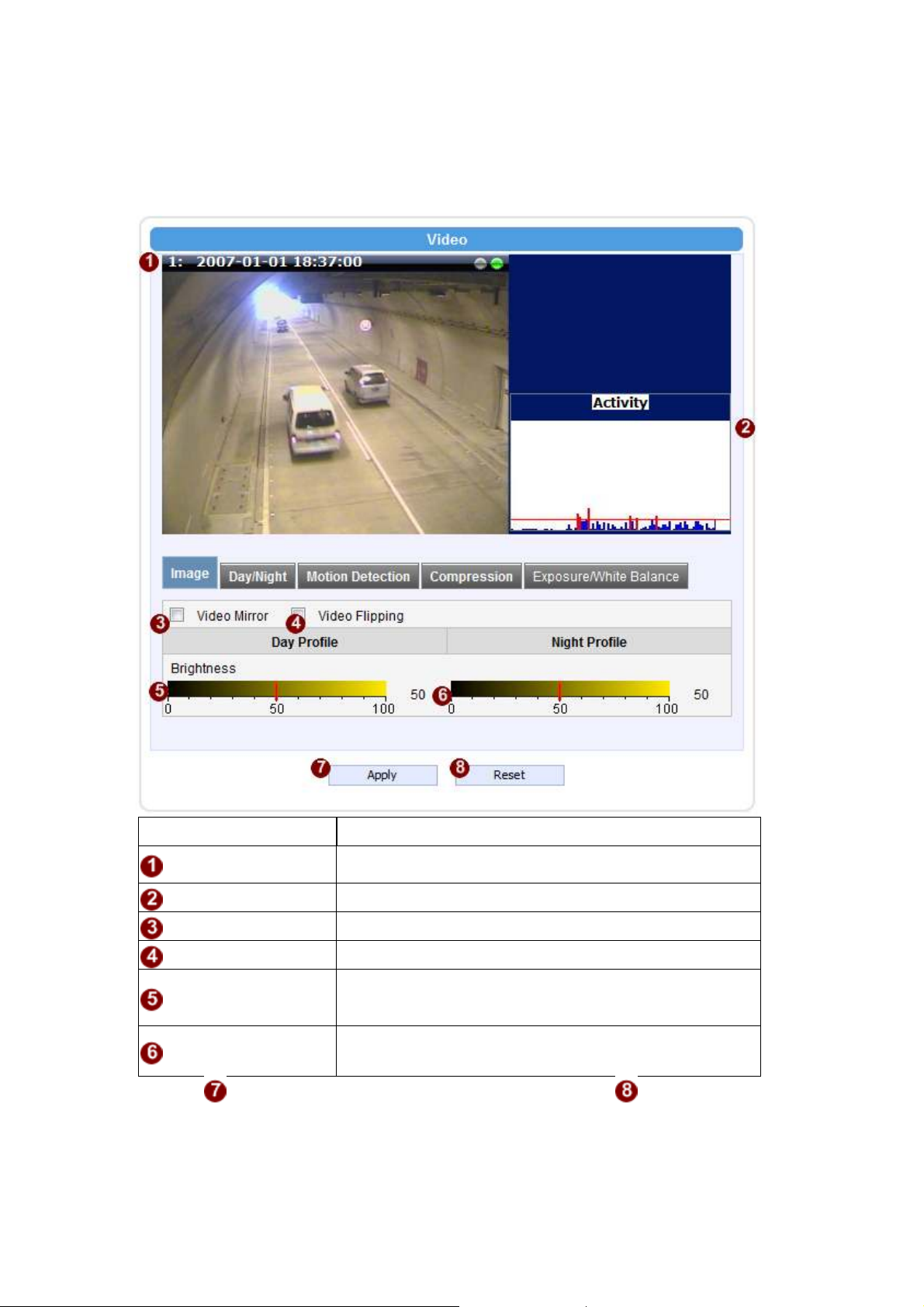
Image (CCD Models)
This tab concerns the general video settings. Please refer to the table below for functions.
Parameters Description
Live View
Activity
Video Flipping
Video Mirror
Live view of the camera
Motion activity status
Check this box to flip the video up-down
Check this box to mirror the video left-right
Brightness
(Day Profile)
Brightness
(Night Profile)
Select the daytime brightness value
Select the nighttime brightness value
Click the [Apply] button to confirm the settings or click the [Reset] button to
re-enter the parameters.
2-35
Page 40

Day/Night (CMOS Non-D/N Models)
This tab concerns the day and night switch timing for your camera. Please refer to the
table below.
Parameters Description
Switch from Day
mode to Night
mode
This value controls the level of light where camera
switches into night mode. Increasing it will make
camera switch to night mode at a darker illumination
level.
The camera will only switch day/night status if the
Switch if lasts
more than X
seconds
illumination level stays either above or below the
boundary for this much time. This is to prevent a
temporary brightness change from triggering unnecessary
day/night changes.
This bar shows the illumination level at which cameras go
2-36
Brightness Meter
Page 41
Bar
reading from the camera sensor. The larger the number, the
to night or day mode (Blue bars), and shows the current
detected illumination level (Green bars). Use this bar to
fine tune the day/Night switch timing.
Get Current
Exposure Level
Clicking this button will refresh the illumination level
darker the environment.
Click the [Apply] button to confirm the settings or click the [Reset] button to
re-enter the parameters.
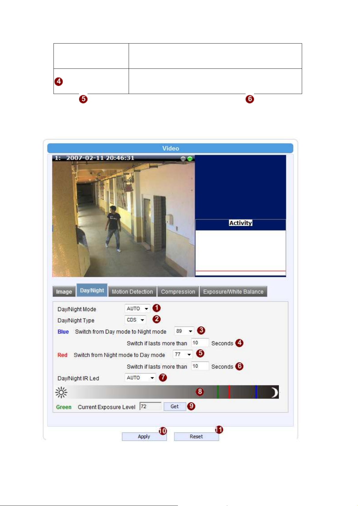
Day/Night (CMOS D/N Models)
2-37
Page 42

it is set as AUTO, LED will turn on in night mode and turn
off in day mode. If set to Disabled, LED will stay off when
reading from the camera sensor. The larger the number, the
Parameters Description
Select the day/night mode.
Auto: The camera would switch between day and night
mode automatically. It will follow Day to Night and Night
Day/Night Mode
to Day threshold defined by user below.
Day: The camera will stay in day (Color) mode.
Night: The camera will stay in night (black & white)
mode.
Select the method used by Camera to determine
Day/Night Type
illumination level. It can be either CDS light sensor or
through image analysis by DSP. Not every model will
allow selection for this.
Switch from Day
mode to Night
Check box to enable the B2 frame in RTP streaming
mode
The camera will only switch day/night status if the
Switch if lasts
more than X
seconds
illumination level stays either above or below the
boundary for this much time. This is to prevent a
temporary brightness change from triggering unnecessary
day/night changes.
Switch from Night
mode into Day
Mode
This value controls the level of light where camera
switches into Day mode. Increasing it will make
camera switch to night mode at a darker illumination
level.
The camera will only switch day/night status if the
Switch if lasts
more than X
seconds
illumination level stays either above or below the
boundary for this much time. This is to prevent a
temporary brightness change from triggering unnecessary
day/night changes.
IR LED may be configured as AUTO or Disabled here. If
Day/Night IR LED
camera switches into night mode.
This bar shows the illumination level at which cameras go
Brightness Meter
Bar
to night or day mode (Blue / Red bars), and shows the
current detected illumination level (Green bars). Use this
bar to fine tune the day/Night switch timing.
Get Current
Exposure Level
Clicking this button will refresh the illumination level
darker the environment.
Click the [Apply] button to confirm the settings or click the [Reset] button to
re-enter the parameters.
2-38
Page 43

Day/Night (CCD D/N Models)
This tab concerns the day and night switch timing for your camera. Please refer to the
table below.
Parameters Description
Select the day/night mode.
Auto: The camera would switch between day and night
mode automatically. It will follow Day to Night and Night
Day/Night Mode
to Day threshold defined by user below.
Day: The camera will stay in day (Color) mode.
Night: The camera will stay in night (black & white)
mode.
2-39
Switch from Day
This value controls the level of light where camera
Page 44

mode to Night
reading from the camera sensor. The larger the number, the
mode
switches into night mode. Increasing it will make
camera switch to night mode at a darker illumination
level.
Switch from Night
mode into Day
Mode
This value controls the level of light where camera
switches into Day mode. Increasing it will make
camera switch to night mode at a darker illumination
level.
This bar shows the illumination level at which cameras go
Brightness Meter
Bar
to night or day mode (Blue / Red bars), and shows the
current detected illumination level (Green bars). Use this
bar to fine tune the day/Night switch timing.
Get Current
Exposure Level
Clicking this button will refresh the illumination level
darker the environment.
Click the [Apply] button to confirm the settings or click the [Reset] button to
re-enter the parameters.
How it works
An important feature in this screen is that user may now customize the illumination level
to perform day/night mode switches.
On the horizontal brightness meter shown here, there are three colored bars. The bar
represents light amplifying levels 0 to 100, where 0 is Brightest and 100 is darkest. 0
means no digital amplification of incoming light signals, which means that the
environment is bright enough for the camera to get good quality images.
When the environment gets darker, as when the sun is setting over the horizon, the
environmental gets darker. To maintain proper image brightness level, the camera will
attempt to digitally amplify the light signals received by the sensor. The Blue one is the
level at which camera will go into night mode, and remove Mechanical IR cut filter and
open IR LED if available. The red one indicates the illumination level at which the
camera will consider bright enough to go back to day (Color) mode.
The Red bar should always be to the left of the blue bar. As camera go from day to night
mode, more lights are allowed inside (the IR filter is removed), so the detected light
signal level will increase. If the night-to-day illumination level is too close to the
day-to-night level, the camera will immediately consider it bright enough to go back to
day mode, which will result in continuous day/night switching.
2-40
Page 45

Motion Detection
Adjust Column
Adjust
Square
Click the
[Apply] button to confirm the settings or click the [Reset] button to
re-enter the parameters.
Video Motion Detection:
STEP1: Click the Plus sign to expand the Motion Detection settings then Click
the Motion Enable checkbox to enable motion detection.
2-41
Page 46

STEP2: Click the checkbox to enable motion detection for each individual region.
STEP3: Click one region to start to edit its size and location. You can click the “Adjust
Column” to drag motion region to your desired location. You can click the “Adjust
Square” and drag to adjust motion region size. You can click the upper right button to
cancel this motion region. Repeat above procedure to adjust the motion region.
STEP4: Set the sensitivity of motion detection region.
STEP5: Set the interval time of motion detection. After a motion event is triggered,
no more events will be triggered within this time in the same region
STEP6: Set the trigger threshold of motion detection region. The larger this value,
the larger the object size needed to trigger motion detection.
STEP7: In motion activity window, the bar shows the motion activity status. You
can also see the trigger threshold (Red line). When the motion activity exceeds the trigger
threshold, the bar would become red to indicate that a motion event has been triggered.
While viewing the motion activity window, you can adjust the motion sensitivity (the
higher, the easier camera considers video change to be an activity) and the threshold (the
higher, the larger the activity needed to trigger a motion event). If the default settings are
not satisfactory for your scene, you may try our alternative recommendations of:
Sensitivity: 80, Threshold: 2~5 (for normal environment)
Sensitivity: 80, Threshold: 5~10 (for very noisy environment)
PIR (Passive Infra Red motion sensors) (Not available to all models)
PIR sensors are available for some models. For the models with PIR, there will be a PIR
Motion Sensor section below the video motion detection.
You may enable PIR sensors by the checkbox and modify the sensitivity/ trigger
interval.
When motion is detected via PIR sensor, a red border will show around the whole view
area.
Please note that PIR sensors have a shorter range of detection than Video motion
detection.
2-42
Page 47

Compression
There are two streams output available for this network device. Click the [Stream 1] or
2-43
Page 48

[Stream 2] item to display the content page, Contents for both stream are identical. Refer
to the table below for how to configure each setting.
Parameters
Description
Encoder Type
Resolution
Frame rate
Video Bit
Rate Mode
Quality
GOP Length
Frame rate
Video Bit
Rate Mode
Video Max
Bitrate
Video Bitrate
Frame rate
Select the encoder’s compression type.
MPEG-4 / MJPEG / H.264
Select the video resolution of the IP device.
Select the available frame rate from the drop down menu.
Select the video bit rate mode.
Constant Bit Rate: The bit rate remains constant at all
conditions.
Variable Bit Rate: The video bit rate will vary based upon
scene complexity and amount of movement. The quality will
remain the same.
When encoder type is MPEG4 or H.264, and video bitrate mode
is “Variable Bit Rate” Select the quality value from High /
Medium / Low
When encoder type is MPEG4 or H.264. and video bitrate mode
is “Variable Bit Rate”. Select the Interval between two I-frames.
This is also called GOP Length. (Group of Picture) . Default
value is one I frame per second. The maximum length of GOP is
limited to 60.
Select the available frame rate from the drop down menu.
This puts a hard cap on the maximum bit rate allowed in any
given second of video streaming. Assigning a limited bit rate
may result in a few dropped frames rate when the stream data
overflows the allowed bit rate. Doing so will also disable Bit
Rate setting below.
Select the video bit rate mode.
Constant Bit Rate: The video bit rate remains constant at all
conditions.
Variable Bit Rate: The video bit rate will vary based upon scene
complexity and amount of movement. The quality will remain
the same.
This puts a hard cap on the maximum bit rate allowed in any
given second of video streaming. Assigning a limited bit rate
may result in a few dropped frames rate when the stream data
overflows the allowed bit rate. Doing so will also disable Bit
Rate setting below.
This is the target bitrate that the camera will attempt to provide
when using Constant Bitrate mode. The actual value will
fluctuate slightly based on scene changes.
Select the frame rate for each profile by choosing from the drop
2-44
Page 49

(Stream2)
down list. Frame rates available for stream 2 may be less than
stream 1, depending upon the setting.
Quality
When encoder type is MJPEG:
Select the quality value of MJPEG encoder type from 1 to 100.
Click the
[Apply] button to confirm the settings or click the Reset] button to
re-enter the parameters.
Exposure / White balance
2-45
Line Frequency
WDR Mode
WDR Level
Change settings between 60Hz or 50Hz,
depending on the AC power type of your region..
This determines if the WDR processing is turned
on or off. Turn this on only when you have very
large brightness differences in a single scene.
Otherwise leave it off.
The strength of image modification by WDR
algorithm. Increasing this will increase the effect
of WDR processor.
Page 50

Select exposure mode to auto or manual.
NOTE: This setting will be lost after you
1. Auto: The IP camera will adjust the
exposure automatically.
Exposure Mode
White Balance
2. Manual: Manually select the
Gain and Shutter Speed below. Day and
night mode change will not operate as normal
under manual Exposure.
Exposure
Select the white balance mode. After you set the
parameter, you need to wait for 5~10seconds to
see the final result.
1. AUTO : Auto white balance (default)
2. INDOOR1: Select the indoor white
balance profile 1.
3. INDOOR2: Select the indoor white
balance profile 2.
4. OUTDOOR1: Select the outdoor white
balance profile 1.
5. OUTDOOR2: Select the outdoor white
balance profile 2
6. HOLD: Select this to let the IP camera
automatically obtain a best white balance
setting according to current environment.
The IP camera will use this setting to
adjust color.
reboot the camera.
2-46
R Gain
(Manual White balance
mode only)
B Gain
(Manual White balance
mode only)
Exposure Gain (In Manual
Exposure Mode only)
Shutter Speed
(In manually shutter mode
only)
7. MANUAL: Select this to enable manual setting
of the white balance. You will need to enter the
R Gain and B Gain setting below.
Add or decrease redness to the video when under
Manual White Balance mode. (This function is
only available in Manual White balance mode.)
Add or decrease blueness to the video when under
Manual White Balance mode. (This function is
only available in Manual White balance mode.)
Select the exposure Gain of the IP camera. The
higher the value = brighter images. (1 ~ 255)
Increase or decrease the shutter speed. The closer
the number is to 1, the better nighttime
performance is, although this also causes motion
blur to the video.
Page 51

Exposure Mode
NOTE: This setting will be lost after you
White Balance
(In
Indoor/Outdoor/Auto/Hold
profiles only)
Select exposure mode to auto or manual.
1. Auto: The IP camera will adjust the
exposure automatically.
Manual: Manually select the
Exposure Gain
and Shutter Speed below..
Select the white balance mode. After you set the
parameter, you need to wait for 5~10seconds to
see the final result.
1. AUTO : Auto white balance (default)
2. INDOOR1: Select the indoor white
balance profile 1.
3. INDOOR2: Select the indoor white
balance profile 2.
4. OUTDOOR1: Select the outdoor white
balance profile 1.
5. OUTDOOR2: Select the outdoor white
balance profile 2
6. HOLD: Select this to let the IP camera
automatically obtain a best white balance
setting according to current environment.
The IP camera will use this setting to
adjust color.
reboot the camera.
For all the settings above, you will need to
setup the value for
AE Reference Target
and Maximum auto shutter speed.
7. MANUAL: Select this to enable manual setting
of the white balance. You will need to enter the
R Gain and B Gain setting below.
AE Reference Target This is the desired image brightness output level.
The camera will attempt to change the exposure
levels or digital amplification levels to achieve this
level of brightness. Increasing this may provide a
brighter image, but if there are extremely dark
areas, this may also create slightly more noise in
the underexposed areas.
Maximum auto shutter
speed
The maximum allowed time for the camera to take
a single image.
Click the [Apply] button to confirm the settings or click the [Reset] button to
re-enter the parameters.
2-47
Page 52

Audio
Audio In Select to enable or disable the audio in function.
Audio In sensitivity Select the sensitivity of audio microphone.
Audio Out Volume Adjust the Audio Out volume.
Click the [Apply] button to confirm the settings or click the [Reset] button to
re-enter the parameters.
2-48
Page 53

OSD/Privacy Mask
OSD (On Screen Display) and Privacy masks are configured in this section. There are
four regions available. Each may be used either as a Privacy mask or an OSD text.
2-49
Page 54

Parameters
Enable
Description
Check this box to enable each OSD / Privacy mask region
OSD /
Privacy mask
Color
(Privacy
mask)
Setup
Color(OSD)
Transparent
Position
String
Format
Format
Notice
Each region can be in one of two types. OSD (On Screen
Display) or Privacy mask
This determines the color of the Privacy Mask Area. You may
choose between Black, Green, Red and Blue.
Click this checkbox to enable Privacy mask area setup. Click and
drag the adjust square at the lower right to change dimensions,
click and drag the adjust column at the top to move. (Similar to
Motion Detection Region)
This determines the color of the OSD Text. You may choose
between Black, Green, Red and Blue.
This number determines the level of transparency for this OSD
Text. 1 means that the background between the texts will not be
visible, while 100 means the background will show through the
OSD text.
Select the location where the text will appear in the image.
This is where you enter the user defined string (%U) as described
in the next section
This controls what is shown in the OSD text. You can click the
Format Notice to the corner for a full list of available parameters.
The OSD text is primarily based upon this field.
Click here to see the syntax list of how to configure the OSD
text.
Click the
[Apply] button to confirm the settings or click the [Reset] button to
re-enter the parameters.
2-50
Page 55

2.3.6 System
Click the
[System] item on the “Setup Page”.
User Account
Click the [User Account Setting] item to display the “User Account Setting Page”.
Setup the account names and their respective passwords. There are 1 root (administrator)
account and 10 common user accounts . Administrator account allows the user to
watch the live view and setup everything; but common user account allows user only to
watch the live image.
Click the check box to enable “Anonymous preview”. When it is enabled, user can
2-51
Page 56

login this camera to view video without input account and password. But user will be
required to input account and password if they want to change any setting
Click the [Apply] button to confirm the settings or click the [Reset] button to
re-enter the parameters.
System Info
Click the [System Info] item to display the “System Information Page”. This shows
details about this IP device including system information, WAN status and system log.
Refer to the table below for how to configure each setting.
View the information at the 3 textboxes. This information is very useful to understand
the IP device status and to resolve any problem that might occur.
2-52
Page 57

Column Description
System info
WAN status
System log
Click [Parameter List] where you may see all configurations of the IP device.
Click [Server Report] to export related information of the IP device while
reporting a support to your support channel.
It shows the firmware version, MAC address, production ID, and
factory default type of IP device.
It shows the WAN port’s IP address, netmask, gateway, DNS
server, DDNS host and connection status.
It shows the system event. This column is very useful to as a
diagnostic tool.
Factory Default
Click the [Factory Default] item to display the “Factory Default Page”.
If you want to keep network settings and restore other settings to factory default, please
click radio box . If you click instead , all the settings would be lost. You will
have to use factory default IP setting to connect to this camera. Please refer to previous
login section.
If you want to reset all setting to default, click to select this radio box .
Click the [Apply] button to show a warning dialog that reminds you again before
restoring the device to factory default.
2-53
Page 58

Firmware Upload
Click the [Firmware Upload] item to display the “Firmware Upgrade Page”. Upgrade the
IP device’s firmware through this page with the following instructions.
Click [Apply] button. The ‘’Firmware Upgrade Page-2” will be displayed as below.
Click the [Browse] to select the upgrade image file and click the [enter]. You can
always get the latest version at our website.
Click the [Apply] button to start upgrading
The upgrade process window will show a progress bar indicating upgrade status. You can
click the [Cancel] button to stop the firmware upgrade.
2-54
Page 59

Once the process is finished, the progress bar will show the upgrading as OK, and reboot
the IP device system.
NOTE: If you cancel the firmware upgrade during upgrade process, the browser window will be
closed
Profile Upload
Profiles are sets of parameters that control how the image sensor behaves. Sometimes
profiles are fine-tuned again to suit a specific environment, or for generally better image.
They are not updated as frequently as firmware, and a good profile can stay in use for a
very long time. Occasionally, you may wish to load a new profile pack into your camera.
This section tells you how to upgrade IP Camera’s Profile Pack.
Click the [Profile Upload] item to display the “Profile Upload Page”.
STEP1: Click [Apply] button. The ‘’Profile Pack Page-2” will be displayed as
below.
STEP2: Click the [Browse] to select the new profile pack and click [enter]. You
can always get the latest version at our website.
2-55
Page 60

STEP3: Click the [Apply] button to start upgrading
STEP5: The upgrade process window shows a progress bar indicating upgrade status.
STEP6: The system will reboot after profile upload.
Save & Reboot
This section tells you how to save all the settings and reboot this IP device. This is
critical because some settings might not take effect before save and reboot. Click the
[Save & Reboot] item to display the “Reboot Page”.
The Action LED indicator will go dark to indicate that the IP device is rebooting. After
around 30 seconds, the Action LED will light up again to indicate that the reboot is
completed.
Logout
Clicking this item allows you to log out of the IP device. Be sure to logout this IP device
once your setting is completed.
2-56
Page 61

APPENDIX
3
3.1 Specification
3.1.1 SIPMPH Camera Series
* Network Spec.
Video Compression
Compression H.264 Baseline / MPEG-4 SP / M-JPEG
SXGA (1280x1024) at 18 fps
Resolution
Image Frame Rate
Audio Input
Compression 8kHz, Mono, PCM
Audio Line Input Unbalanced, 1.4 Vp-p 1Vrms, terminal Block
Audio Output
Compression 8kHz, Mono, PCM
Audio Line Output Unbalanced, 1.4 Vp-p 1Vrms, terminal Block
External I/O
Reset Button Factory default
Alarm(SIPMPT Only)
Digital Input 1, terminal bloc
Transistor Output 1, terminal block
Network
Ethernet Ethernet(10/100 Base-T),RJ-45 connector
Protocol
Software
Web Browser MS Internet Explorer 6.0 or above
Security Password protection: configured by the administrator
Compatibility Most major 3rd party software suites
NVR Software Included at no additional charge
HD720 (1280x720) at 26fps
VGA (640x480) at 30 fps
Up to 18 fps at SXGA resolution; Up to 26 fps at HD720
resolution; Up to 30 fps at VGA resolution
TCP, UDP ,IP, HTTP, DHCP, PPPoE, RTP, RTSP, FTP, SMTP,
DNS, DDNS, NTP, ICMP, IGMP, ARP, #GPP
2-57
Page 62

* Camera Spec.
SIPMPBVFH
Image Sensor 1/3" Micron Progressive Scan CCD
Effective Pixels 1280 x 1024
Electric Shutter
Lens Varifocal Lens f=3.3~12mm
Min. scene Illumination 0.5 Lux at F1.0 (2400K, 30IRE)
Synchronization Internal
S/N Ratio Better than 44 dB
Flickerless 1/120 sec(60Hz), 1/100 sec(50Hz)
Day/Night Mechanical IR Cut Filter
White Balance
AGC Automatic (User defended)
BLC YES
Motion Detection Yes (3 Windows)
Power Source
Operational Temperature -29℃ ~ +50℃ ( - 20℉ ~122℉ )
Operational Humidity 30% ~90% RH
Dimensions(WxHxD) 92 x 85 x 264 mm
Weight 1.3kg
1/10 ~ 1/2,000sec (60Hz)
1/10 ~ 1/2,000sec (50Hz)
6Mode(AUTO,INDOOR1/2,OUTDOOR1/2,HOLD
CURRENT,MANUAL) Configurable
DC12V (300mA)
PoE (IEEE802.3af) with Class 3
2-58
Page 63

SIPMPDVFH
Image Sensor 1/3" Micron Progressive Scan CCD
Effective Pixels 1280 x 1024
Electric Shutter
Lens Varifocal Lens f=3.3~12mm
Min. scene Illumination 0.5 Lux at F1.0 (2400K, 30IRE)
Synchronization Internal
S/N Ratio Better than 44 dB
Flickerless 1/120 sec(60Hz), 1/100 sec(50Hz)
Day/Night Mechanical IR Cut Filter
White Balance
AGC Automatic (User defended)
BLC YES
Motion Detection Yes (3 Windows)
Power Source
Operational Temperature -29℃ ~ +50℃ ( - 20℉ ~122℉ )
Operational Humidity 30% ~90% RH
Dimensions(HxD) 132 ø x 120.85 mm
Weight 1.4kg
1/10 ~ 1/2,000sec (60Hz)
1/10 ~ 1/2,000sec (50Hz)
6Mode(AUTO,INDOOR1/2,OUTDOOR1/2,HOLD
CURRENT,MANUAL) Configurable
DC12V (300mA)
PoE (IEEE802.3af) with Class 3
2-59
Page 64

2-60
200 New Highway
Amityville, NY 11701
631-957-8700
www.specotech.com
Rev.100518
Speco Technologies is constantly developing product improvements.
We reserve the right to modify product design and specifications without notic e
and without incurring any obligation.
 Loading...