

Page 1

Intensifier Series
Camera
HT-INTD3
HT-INTD4
200 New Highway
Amityville, NY 11701
631-957-8700
www.specotech.com
Please read this manual thoroughly before operation and keep
it handy for further reference.
Page 2
Page 3
Contents
Package Contents
Precautions
Camera Installation
Internal Components
Features
3
4
5
6
7~8
Operating Your Camera
----------------------9~10
* SET UP --------------------------------------------------------------11~12
* SET UP LENS-------------------------------------------------------13~14
* SHUTTER SPEED CONTROL ----------------------------------15~18
* BACK LIGHT--------------------------------------------------------------19
* AUTO GAIN (AGC) -----------------------------------------------------20
* WHITE BALANCE --------------------------------------------------21~22
* REDUCE NOISE---------------------------------------------------------23
* INTENSIFIER-------------------------------------------------------------24
* CAMERA TITLE-------------------------------------------------------25~26
* DAY/NIGHT/SYNC---------------------------------------------------27~28
* MOTION DETECTION-----------------------------------------------29~30
* PRIVACY-------------------------------------------------------------------31
* REVERSE------------------------------------------------------------------32
* DETAIL----------------------------------------------------------------------33
* DEFAULT/RETURN-----------------------------------------------------34
Troubleshooting
Specifications / Dimensions
Warranty
35~36
37~38
39
1 2
Page 4

PACKAGE CONTENTS
PRECAUTIONS
• HT-INTD CAMERAS SHOULD BE ONLY INSTALLED BY
QUALIFIED PERSONNEL
• Please make sure that the following items are included
in the package:
1 HT-INTD Camera
1 Remote Controller
1 IR Receiver
4 Mounting Screws
1 Allen Wrench
1 Allen Bit
1 Power Cable Adaptor (for optional use)
Please leave this manual with the end-user for future
reference.
• TO PREVENT A FIRE OR ELECTRICAL HAZARD PLEASE USE
PROER POWER CABLE.
• DO NOT CELAN THE COVER WITH AN ABRAISIVE CLEANING
MATERIAL - PLEASE USE A SOFT CLOTH OR TISSUE TO
CLEAN THE DOME COVER
• THERE ARE NO USER-SERVIEABLE PARTS INSIDE. PLEASE
DO DISASSEMBLE THIS CAMERA OTHER THAN TO MAKE
INITIAL ADJUSTMENTS.
• PLEASE USE A UL APPROVED REGULATED 24 VOLT AC OR
12 VOLT DC POWER SUPPLY
• PLEASE USE APPROPRIATE LOW VOLTAGE POWER CABLE
TO PREVENT FIRE OR ELECTRICAL SHOCK.
• PLEASE INSURE THAT YOUR INSTALLATION AREA CAN
SUPPORT THE WEIGHT OF THE CAMERA.
• PLEASE HANDLE THIS CAMERA CAREFULLY:
- DON’T EXPOSE THE CAMERA TO DIRECT SUN
3 4
Page 5
CAMERA INSTALLATION
INTERNAL COMPONENTS
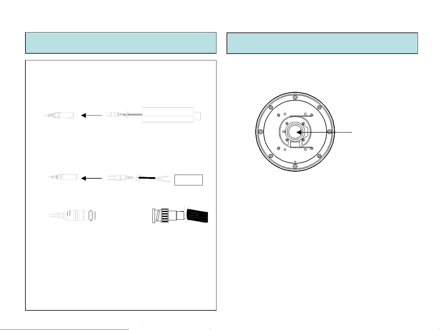
Connections:
1. When using 12-Volts DC (constant voltage 600mA)
-CONNECT POWER TO THE POWER JACK.
POWER INPUT:RED
CENTER:(+)
2. When using 24-Volts AC (40 VA)
-CONNECT ACCESSORY CABLE TO THE POWER JACK AND
CONNECT AC 24V TO THE LEAD.
POWER INPUT:RED
CENTER:(+)
3. CONNECT VIDEO CABLE
-CONNECT BNC CABLE TO THE BNC JACK.
Note: All connections can be made directly to the PCB if desired
connect
connect
AC 24V
YELLO W: VIDEO O UT
1. Structure
DC Auto lris
4~9m or 5~50mm
(1) DC AUTO-IRIS LENS
Adjust between TÅÆW (TELE ÅÆ WIDE) to set the angle (focal
length)
Set the focus by adjusting 쏒N
NOTE: BOTH OF THE ABOVE ADJUSTMENTS GET LOCKED
INTO POSITION THROUGH THE USE OF "LOCKING HANDLES".
5 6
Page 6

Features
♣ SLC
When the image is in front of strong background lighting,
your camera allows you to get the best image.
♣ INTENSIFIER
1/3 inch high density CCD and digital processor permit
high quality pictures to be captured in very low light
conditions.
♣ High Resolution
Horizontal resolution of 530TV lines is
achieved by using a SONY Double Speed CCD with
410,000 pixels, yielding pictures with a high S/N ratio.
♣ OSD
All camera functions are menu driven for easy use.
♣ Dynamic Noise Reduction
The Intensifier camera has a DSP chip that can
remove image noise, showing clean images in
low light conditions.
♣ ELECTRONIC DAY / NIGHT
The Intensifier camera can show color pictures in all lighting
conditions, or you can have it automatically switch to a B/W
picture in low light conditions
♣ Motion Detection
Built in motion detector with adjustable areas of coverage will
flash a warning on the screen when motion is detected.
7 8
♣ MANUAL / AUTO IRIS LENS
The Intensifier camera will work with auto iris,manual iris and
fixed iris lenses.
Page 7
Operating your camera
◈Functions
SET UP MENU
LENS OPTION
●DC ●MANUAL
SHUTTER
●OFF ●F/L ●MANUAL
WHITE BALANCE
●ATW ●AWC MANUAL●
SLC – ( Speco Light Compensation )
●OFF ●LOW ●MIDDLE ●HIGH
Auto Gain
●OFF ●LOW ●MIDDLE ●HIGH
REDUCE NOISE
●OFF ●LOW ●MIDDLE ●HIGH
INTENSIFIER
●AUTO ●OFF
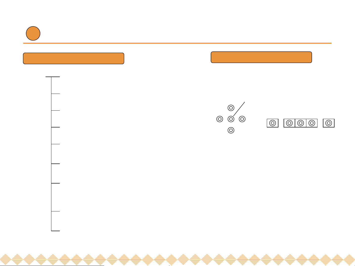
◈OSD Menu Setting
UP
LEFT
DOWN
SET
RIGHT
LEFT
SET DOWNUP
NEXT PAGE
●CAMERA TITLE ●DAY/NIGHT ●SYNC
●MOTION ●PRIVACY ●REVERSE
●DETAIL ●DEFAULT ●PAGE 1
EXIT
9
10
Page 8

Operating your camera
1. When controledl by RS-485, Pelco-D protocol (Option), refer to the following.
A. DIP Switch Setting on the Camera
(Factory default : Camera Address = 01, Baud Rate = 2400bps)
①②
①
RS485 Address Set
RS485 Baud rate Set
②
•Up to 15 Cameras can be
controlled by 1 IR Remote
Controller & 1 Receiver. You
must set up each camera’s
address by DIP Switches for
proper addressing.
B. Receiver Setting to use with IR Remote Controller
(Factory default : Baud Rate = 2400bps, Chart is same as
above)
Buzzer On/Off
Power Connector
(DC12V in)
485(+),(-)
Baud Rate Setting
C. System Integration
•Please Observe Polarity!
485(+)
485(-)
Receiver
IR Remote
Multiflexer
Monitor
Controller
CCD Camera
D. IR Remote Controller
-Can call and control each camera on the monitor by the following.
SET / Menu buttonUP button
LEFT button
RIGHT button
DOWN
button
When you call Camera Address
01
->Push 0 Button
->Push 1 Button
->Push CAM Button
11 12
Page 9

Operating your camera Operating your camera - LENS
1. Press the SET button to access the SETUP mode.
●SETUP menu is displayed on the monitor screen.
2. Select the desired feature using the UP or DOWN button.
●Each time you press the UP or DOWN button, the arrow
indicator moves up or down.
●Move the arrow indicator to the desired feature item.
3. Change the status of the selected feature using the LEFT
or RIGHT button.
4. When completed, move the arrow indicator to ‘EXIT’ and press
the SET button.
1) Setting up the LENS
Select the lens by pressing the RIGHT button.
① On the SETUP menu screen, move the arrow indicator to the lens
using the UP or DOWN button.
② Select the desired feature using the LEFT or RIGHT button.
Notes
•●You can access the submenu by using SET button.
•●For the mode with ’---’, you may not access submenu.
13 14
Page 10

Operating your camera – SHUTTER SPEED CONTROL①
▶When the DC LENS is selected, press the SET button
to control the BRIGHTNESS.
Notes
●AUOT IRIS LENS (DC TYPE) is recommended
2) Shutter status and speed control
You can control brightness of the screen by the shutter speed.
① Press the SET button to display the setup menu and move the arrow
indicator to ‘SHUTTER’ using the UP or DOWN button.
② Set ‘SHUTTER’ to the desired mode using the LEFT or RIGHT
button.
▶OFF : Deactivation
▶FLK (1/100) : Flicker mode
15 16
Page 11

Operating your camera –SHUTTER SPEED CONTROL ②
▶MANUAL : When setting shutter speed manually.
You can select speed from ‘1/60’ to ‘1/200,000’sec
▶ELC : You can control the BRIGHTNESS.
③ When completed, press ‘SET’
Notes
●Avoid pointing the camera directly at a fluorescent lamp.
●When the SHUTTER menu is set to FLK mode, the INTENSIFIER
will not work.
17 18
Page 12

Operating your camera - BACKLIGHT
3) SLC (Speco Light Compensation) - BACKLIGHT
A built-in SR chip provides intelligent light level control to overcome
severe Backlight conditions.
① Press the SET button to display the SETUP menu and move the
arrow indicator to ‘SLC’ using the UP or DOWN button.
② SET ‘SLC’ to the desired mode using the LEFT or RIGHT buttons.
▶OFF ▶LOW ▶MIDDLE ▶HIGH
4) AUTO GAIN (AGC)
AGC allows a brighter picture in low light conditions. Higher GAIN level
will yield a brighter screen but you might notice an increase in noise.
① Press the SET button to display the SETUP menu and move the arrow
indicator to ‘AGC’ using the UP or DOWN button.
② SET ‘AUTO GAIN’ to the desired mode using the LEFT or RIGHT button.
▶OFF
▶LOW ▶MIDDLE ▶HIGH
19 20
Page 13

Operating your camera - WHITE BALANCE
5) WHITE BALANCE
① Press the SET button to display the SETUP menu and move the
arrow indicator to ‘WHITE BALANCE’ using the UP or DOWN button.
② Set ‘WHITE BAL.’ to the desired mode using LEFT or RIGHT button.
▶ATW (Auto Tracking White Balance)
: When the color temperature is 2400~12000K, select this mode.
(ex. A fluorescent lamp or outdoors)
▶MANUAL : To fine adjust, select the Manual mode. You can increase
or decrease the red or blue factor while monitoring the difference on
the screen. Set to ‘MANUAL’ mode and press the SET button. Increase
or decrease the value for RED(R-Gain) and BLUE(B-Gain), watching
the color of the picture, and press the SET button when you obtain the
best color.
Notes
●Proper White Balance may not be obtained under the following
conditions, in these cases select the AWC mode.
-When the scene contains a mostly high color temperature object
such as a blue sky or sunset.
-When the scene is dim.
-If your camera faces a fluorescent lamp directly or is installed in an
area with constantly changing illumination.
▶AWC (Auto White Balance Control)
: The white balance is automatically adjusted in a specific environment.
In order to obtain the best result, press the set button while the camera
focuses on white paper. If the environment including the light source is
changed, you have to adjust the white balance again.
21 22
Page 14

Operating your camera - DNR
Operating your camera - INTENSIFIER
6) REDUCE NOISE( Dynamic Noise Reduction)
DNR reduces the video noise on the screen.
① Press the SET button to display the SETUP menu and move
the arrow to ‘REDUCE NOISE’ using the UP or DOWN button.
② SET ‘REDUCE NOISE’ to the desired mode using the LEFT
or RIGHT button.
▶OFF : Deactivation
▶LOW : Low reduction of the noise
▶MIDDLE : Middle reduction of the noise
▶HIGH : High reduction of the noise
7) INTENSIFIER
Allows you to get clear images with this function under night
or low light conditions.
① Press the SET button to display the SETUP menu and move the
arrow indicator to ‘INTENSIFIER’ using the UP or DOWN button.
② SET ‘INTENSIFIER’ to the desired mode using the LEFT or RIGHT
button.
▶AUTO : When your camera is under night or low-light
conditions select this mode. This mode allows the
camera to switch into B/W in low light conditions.
▶OFF : Deactivation
Notes
●If you change the ‘GAIN’ menu from AGC-L to AGC-H, the sensitivity is
increased as well as noise on the screen.
●When the ‘GAIN’ menu is OFF, REDUCE NOISE will not work.
23 24
Notes
● If you press “auto” button in the Intensifier mode, you can
Control the amount of intensification from 2X ~ X128.
● Increasing the amount of Intensification results in brighter pictures
Under low light conditions, and may increase image lag.
● Increasing the amount of intensification may cause image noise
which is to be expected as a normal condition..
Page 15

Operating your camera - CAMERA TITLE①
Operating your camera - CAMERA TITLE②
8) NEXT PAGE
① Press the SET button to display the SETUP menu and move the
arrow indicator to ‘NEXT PAGE’ using the UP or DOWN button.
② SET ‘NEXT PAGE’ to the desired mode using the LEFT or RIGHT
button.
(1) CAMERA TITLE
(2) ① Press the SET button to display the SETUP menu and move the arrow
indicator to ‘CAMERA TITLE’ using the UP or DOWN button.
② SET ‘ON’ using the LEFT or RIGHT button.
③ Press SET button to access the SETUP mode.
④ You can enter up to 15 characters.
a. Move the cursor to character-enter location by using the LEFT
or RIGHT button.
b. Select the desired character by using the UP or DOWN button.
c. Press SET button to confirm the blinking character. The first
character is saved and the cursor in the bottom of the screen
moves to the next position.
d. Repeat above steps until you create the full name you want.
e. Select the position at which the CAMERA TITLE will be located on
the screen.
-Move the cursor to ‘POS’ and press SET button.
-Select the position by using the 4-directional buttons, then press
the SET button to confirm the position.
f. When completed, move the cursor to ‘END’ and press SET button.
Notes
● If the CAMERA TITLE feature is set to ‘OFF’, the name will not
displayed in the monitor.
25 26
Notes
● If you make a mistake while entering the name
Move the cursor to ‘CLR’, press ‘SET’ button.
After erasing the character from right to left, correct the character again.
Page 16

Operating your camera – COLOR/SYNC
(2) COLOR : You can choose color and B/W mode electronically.
① Press the SET button to display the setup menu and move the arrow
indicator to ‘COLOR’ using the UP and DOWN button.
② SET ‘COLOR’ to the desired mode using the LEFT or RIGHT button.
▶COLOR : The camera will always display a color picture
▶AUTO : The camera will switch into the B/W mode under
low light conditions.
Notes
●OSD Key may not work for 3 seconds when the
COLOR/BW mode is changed.
(3) SYNC : Two SYNCHRONIZATION modes are available INTERNAL and
EXTERNAL LINE-LOCK.
① Press the SET button to display the setup menu and move the arrow indicator
to ‘SYNC’ using the UP and DOWN button.
② SET to the desired mode using the LEFT or RIGHT button.
▶INT : Internal synchronization
▶L/L : If you choose ‘L/L’, you can adjust the desired phase.
-Press the SET button.
-You can adjust the desired phase from 0 to 270.
Notes
●When used in AC power, L/L mode can be used.
●In 12V DC, the SYNC menu defaults to ‘Internal.
27 28
Page 17

Operating your camera – MOTION DETECTION
(4) Whenever your camera detects motion, THE WORDS “motion detected’
will appear on the screen.
① Press the SET button to display the setup menu and move the arrow
indicator to ‘MOTION’ using the UP and DOWN button.
② SET ‘MOTION’ to the desired mode using the LEFT or RIGHT button.
▶OFF : Deactivation
▶ON : MOTION. activated
-Press SET button.
-Move the arrow indicator to ‘AREA SET’ using UP and
DOWN button, and then press the SET button.
- Set the areas you want to observe.
29
Max. Min.
30
Page 18

Operating your camera - PRIVACY Operating your camera - MIRROR
(5) PRIVACY : To mask an area that you want to be private.
① Press the SET button to display the setup menu and move the arrow
to ‘PRIVACY’ using the UP and DOWN button.
② SET ‘PRIVACY’ to the desired mode using the LEFT or RIGHT button.
▶OFF : Deactivation
(6) REVERSE
① Press the SET button to display the setup menu and move the
arrow indicator to ‘REVERSE’ using the UP and DOWN button.
② SET ‘REVERSE’ to the desired mode using the LEFT or RIGHT
button.
▶OFF : Deactivation
▶ON : Reverse the image RIGHT or LEFT.
▶ON : PRIVACY mode activated
-Press the SET button.
-Move the arrow to the area you want to mask.
-Set ‘ON’ using LEFT or RIGHT button.
-Press the SET button and then set the area’s
bounds as for Motion detection.
31
32
Page 19

Operating your camera - DETAIL
Operating your camera - RESET/RETURN
(7) DETAIL
① Press the SET button to display the setup menu and move the arrow
indicator to ‘DETAIL’ using the UP and DOWN button.
② SET ‘DETAIL’ to the desired mode using the LEFT or RIGHT button.
▶OFF : Deactivation
▶ON : DETAIL control mode (level 0~31)
When the level is up, the sharpness will increase.
Control this level to get your best picture quality.
If the level is too high, you can get an unnatural image
with video noise.
(8) DEFAULT : Use to reset your camera to FACTORY DEFAULT
SETTING.
(9) PAGE 1 : Save the setting of NEXT PAGE function, and then
move to SET UP menu.
33
34
Page 20

Troubleshooting
If you have trouble operating your camera, refer to the following.
Nothing appears on
the screen.
The image on the
screen is dim.
The image on the
screen is dark.
The camera is not
working properly,
and the surface of
the camera is not.
MOTION DETECTION
function is not active.
SolutionProblem
●Check that the power cord and line connection
between the camera and monitor are attached.
●Check that you have properly connected your video
cables.
●Is the lens stained with dirt? Clean your lens with a
soft, clean cloth.
●Adjust the monitor controls.
●If the camera is exposed to a strong light
change the camera position.
●Adjust the lens’ focus properly.
●Adjust the contrast feature of the monitor.
●If you have an intermediate device, set the
75Ω/Hi-z properly.
●Check that you have properly connected
the camera to an appropriate power source.
●Have you set the ‘MOTION DET.’ menu to off?
●Have you set ‘MD LEVEL’ to too low?
●Have you set ‘MD ARAEA’ properly
Problem
The color of the
picture is not
matched.
The image on the
screen flickers.
L/L mode cannot
be selected.
Solution
●Check that you have properly set the ‘WHITE
BAL’ menu
●Is the camera facing direct sunlight or
fluorescent lighting? Change the camera position.
●Have you connected your camera to DC power
source? Connect it to AC power source.
35
36
Page 21

SPECIFICATIONS
DIMENSIONS
ITEM
LENS Type
HT - INTD3
HT - INTD4
DC 12V & AC 24v ( Dual Voltage )Power Source
280mA(DC) / 3.8W(AC)Power Consumption
1/3”, SONY SUPER HAD CCD, 410,000 pixelsImage Sensor
811(H) x 508(V) , 1/3” CCDTotal Pixels
768(H) x 494(V) , 1/3” CCDEffective Pixe ls
HT - INTD3 (DC AUTO IRIS VARIFOCAL 3~9mm)
HT - INTD4 (DC AUTO IRIS VARIFOCAL 5~50mm)
1 : 1.3 ~2.0Maximum Aperture Ratio
2 : 1 Interlaced 525 Lines / 60 Fields / 30 FramesScanning System
Internal / Line Lock selectableSynchronization
1.0V [p-p] NTSC Composite, 75Ω / BNC ConnectorVideo Output
530 TV LineResolution
AGC-L, AGC-H, OFF selectableGain Control
1/60 ~ 1/200,000 secElectric Shutter Speed
Built-in ( selectable limit ~ X128)INTENSIFIER
ATW / AWC / MANUALWHITE BALANCE
0.002Lux (intensifier) 0.3Lux(sh)Min. Illumination
50dB (Weight On)S/N ( Y signal)
OFF / LOW / MIDDLE / HIGHREDUCE NOISE
MD1 / MD2 / OFFMotion Detection
Built - inOn Screen Display ( O.S.D )
ON / OFF (4 Programmable Zone)PRIVACY Function
-29℃ ~ +50℃ (-20℉ ~120℉)Operational Temperature
to 95% RHOperational Humidity
37
* SIDE VIEW : HT-INTD3
* TOP VIEW : HT-INTD3
38
Page 22

WARRANTY
39
 Loading...