

Page 1

HTSD10X
10X Pan-Tilt Speed Dome Camera
Please read this manual thoroughly before operation and keep it handy for further reference.
Page 2

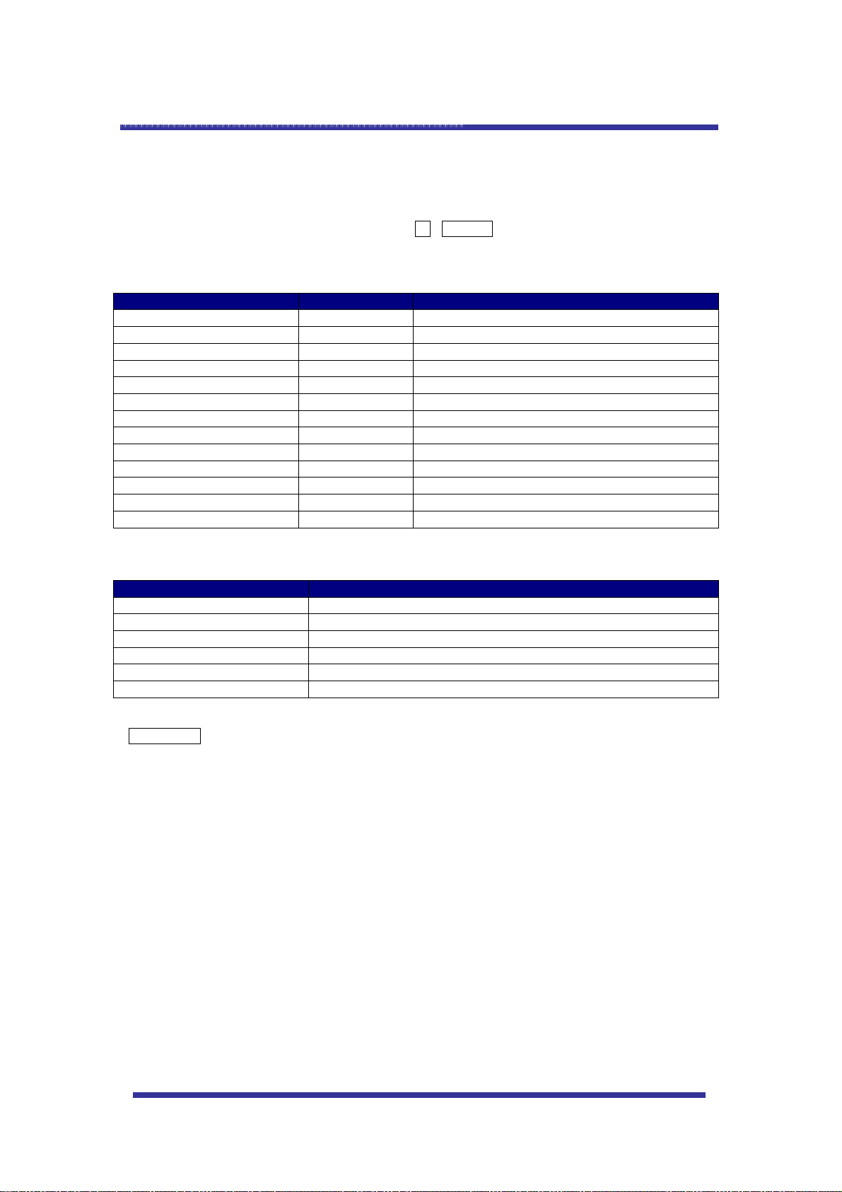
CONTENTS
Warning & Caution
What’s in the Box?
General Features
Names of Each Part
Installation
A. Connection Methods
B. Ceiling Mount Type
C. Embedded Mount Type
Quick Operating Keys
Diagnostic
OSD Menu Setting
A. OSD Menu Table
B. DOME SET
C. CAMERA SET
D. PRESET
E. AUTO SCAN
F. TOUR SET
G. PRIVACY SET
H. PATTERN SET
I. ALARM SET
J. SECTOR SET
3
3
4
5
6
7
8
9
10
11
16
18
19
20
21
22
23
24
DIP Switch Setting
A. ID Setting (DIP SW1)
B. Protocol/ Baud Rate Setting (DIP SW1-9~10)
Trouble Shooting
Specification
Dimension
25
26
27
28
29
2
Page 3
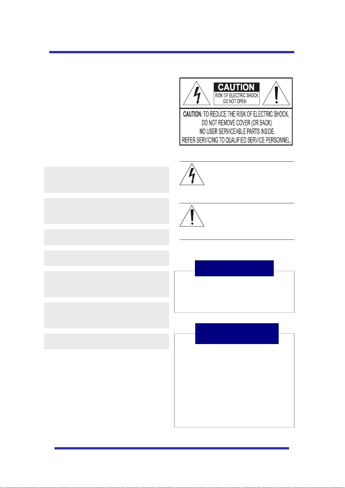
WARNING & CAUTION
If you fail to read this information and
handle the product incorrectly, serious
injury may occur.
Never install the product in area exposed to
oil or gas.
Never install the product on a ceiling that
cannot hold its weight.
Never touch the power cord with wet hands.
Clean only with a dry cloth.
Never install the product in extreme high or
low temperature.
Never drop hit strongly or vibrate the product.
Never touch the front glass of the product.
This symbol is intended to alert the user to
the presence of un-insulated “dangerous
voltage” within the product’s enclosure that
may be of sufficient magnitude to
constitute a risk of electric shock to
persons.
This symbol is intended to alert the user to
the presence of important operating and
maintenance (servicing) instructions in the
literature accompanying the appliance.
Warning
Never move Pan/Tilt by hand. It may
causes serious damage to the camera.
What’s in the Box ?
1. Camera
2. Screws ( Ø4x16 screw 5EA )
3. Terminal block (5pin 2EA)
4. Manual
5. Screw Cap (2 EA)
3
Page 4

GENERAL FEATURES
100X Zoom Mini Speed Dome
10X Optical Zoom with 10X digital zoom
±0.02° dome system accuracy
With 0.1° technical accuracy, camera provides excellent
sensitive and delicate controlling on preset mode by
adapting 1/4 micro step and twin gear system
360° Endless Rotation
10X mini speed dome is capable of endless rotation of 360
degrees
Compensation function: preset position
The function minimizes the appearance of shaky images
caused by low-frequency vibration, wind and any impact
and maintains a normal horizontal resolution and sets the
starting point of pan/tilt on preset mode by using joystick
turning one time without turn off the power of the camera.
It is useful for outdoor surveillance and traffic monitoring
applications.
Over 200°/Sec Preset Speed
The 360° full pan function moves through a maximum of
200°/sec., enabling you to quickly pinpoint the spot you
want to watch. Tilt speed provides through a maximum
200°/sec on preset.
Polarity Protection of Power (DC12V)
Filter changeable - True Day/Night
Surveillance with optimum picture is possible owing to filter
changeable Day/Night (ICR block filter) function and DSS.
Indoor / Outdoor applications
Quick Operation Keys
This camera provides quick functional keys in order to
be easily controlled by any controller or DVR.
Various Surveillance Functions
Auto Scan repeats pan and tilt between two preset
positions with different speed and dwell time.
8 Group Tour up to 8 Programmable Group tours
available and each group consists up to 60 presets with
different speed and dwell time with 16 characters.
164 Preset positions up to 164 programmable
preset positions are available with 16 characters
8 Patterns up to 8 programmable user-defined patters
are available with 16 characters and each one is
consisting 50 seconds, total 400
8 Sectors up to 8 programmable user-defined sectors
are available with 16 characters
4 Privacy Masking Zones up to 4 programmable
user-defined privacy masking zones are available with
16 characters
4 Alarm input up to 4 alarms activate with preset,
tours, patterns.
seconds.
200°/S – Manual speed
This camera provides up to 200°/sec of manual speed
and it’s adjustable from 10°/sec to 200°/sec by each
10°/sec
1/4” Sony Super HAD CCD
Equipped with Sony Super HAD CCD technology, these
cameras provide excellent sensitivity and low smear
levels.
Intelligent Pan/Tilt Controlling
Intelligent Pan/Tilt function continually decreases pan
and tilt speeds in proportion to zoom.
Aluminum case and PC cover
Aluminum body and Poly Carbonated dome cover
(IP66 Rated)
.
Password Protection
4
Page 5
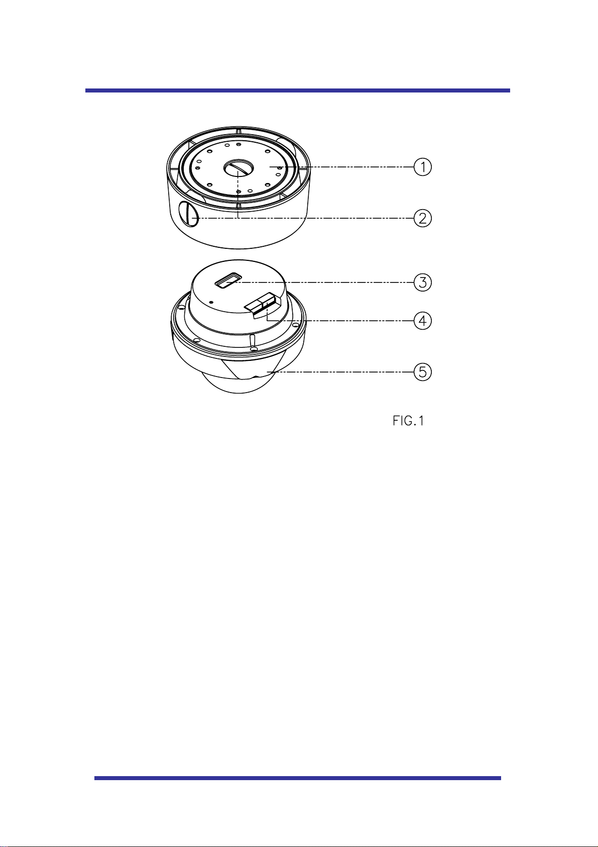
NAMES OF EACH PART
1. Surface Mount Adaptor
2. Cap Screw ( PT3/4 , 2EA )
3. Dip Switch
4. Terminal Block
5. Main body
5
Page 6
INSTALLATION
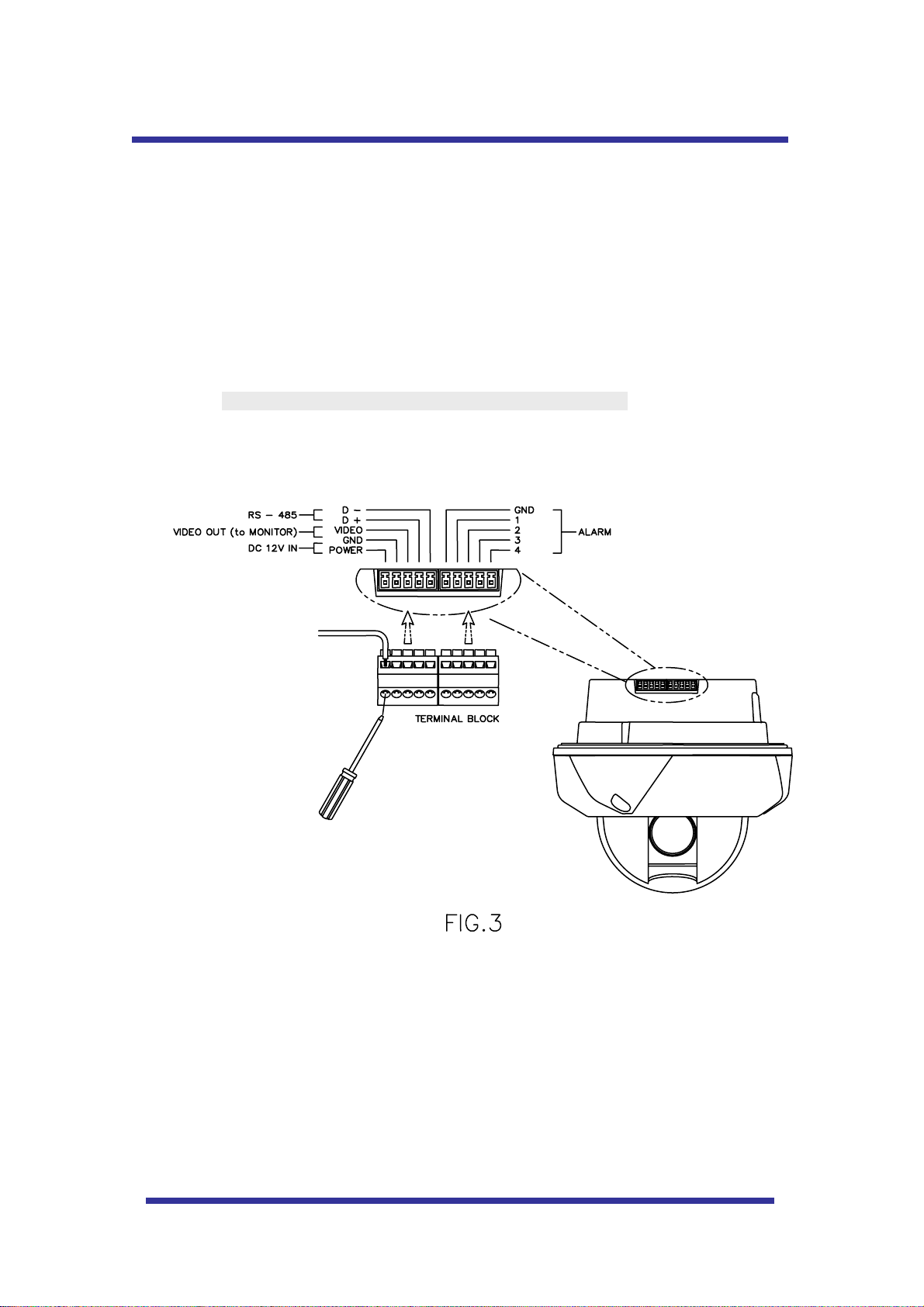
A. CONNECTION METHOD
A-1
1. Loosen the screws on the domes cover and remove it from the base.
(Screws will not come out)
2. Loosen the screws which connect the mount cover and Main base and separate the dome cover
from the main base. (Screws will not come out)
3. Connect power (12 VDC 1.5 A ) to Power and GND.
4. Connect video to Video and GND.
5. Connect communication cable to RS-485 connectors.
6. Connect alarm cable to GND like 1 and GND, 2 and GND, 3 and GND, 4 and GND.
(You can use both N.O / N.C methods.)
z Don’t screw too tightly. It can be the cause of defect.
6
Page 7
INSTALLATION
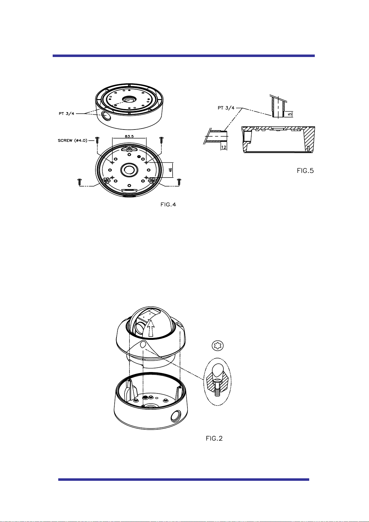
B. MOUNT
1. Attach the surface mount adaptor with 4 screws at the installation site. (FIG.4)
2. When you use pipe, please note the standard size of pipe. (FIG.5)
3. Re-assemble the domes.
7
Page 8
QUICK OPERATING KEYS
1-64 + preset and 101~200 + preset are used for preset and 65-100 + preset used for functions.
For example, to enter OSD MENU, press the button 95 +PRESET.
<Quick Operation Key Table 1, Pelco - D, P>
Number Note Function
1 ~ 64, 100~200 +Preset PRESET Executing Preset 1 ~ 64
65 + Preset PRESET STATUS Display Preset Status
66 +Preset AUTO SCAN Executing Auto Scan
67 +Preset AUTO FLIP Selectable On/Off/Auto in Auto Flip function
71~78 +Preset GROUP TOUR Executing Group Tour #1 ~ #8
81~88 +Preset PATTERN Executing Pattern #1 ~ #8
91 + Preset ZERO POSITION
92 + Preset FREEZE
93 + Preset BLC MODE Selectable On/Off in BLC function
94 + Preset D/N MODE Selectable Day/Night Mode (Auto/Day/Night Mode)
95 + Preset OSD MAIN MENU To enter OSD Main Menu
96 + Preset FOCUS ADJUST Focus adjusting
97 +Preset ALARM Selectable Enable/Disable all Alarms
<Quick Operation Keys Table 2> Use these function keys if controller has these keys>
Menu Function
Tilt Up / Down Sub menu cursor moves up / down
Pan Left / Right Enter to the sub menu or status change or decrement
Focus Near Using for Enter key when user select YES or NO
Focus Far Using for function changing keys when set coordinate
Zoom Tele Status cursor to the right
Zoom Wide Status cursor to the left
* 65 + preset : Status Report , If user presses any key, it disappears.
8
Page 9
QUICK OPERATING KEYS
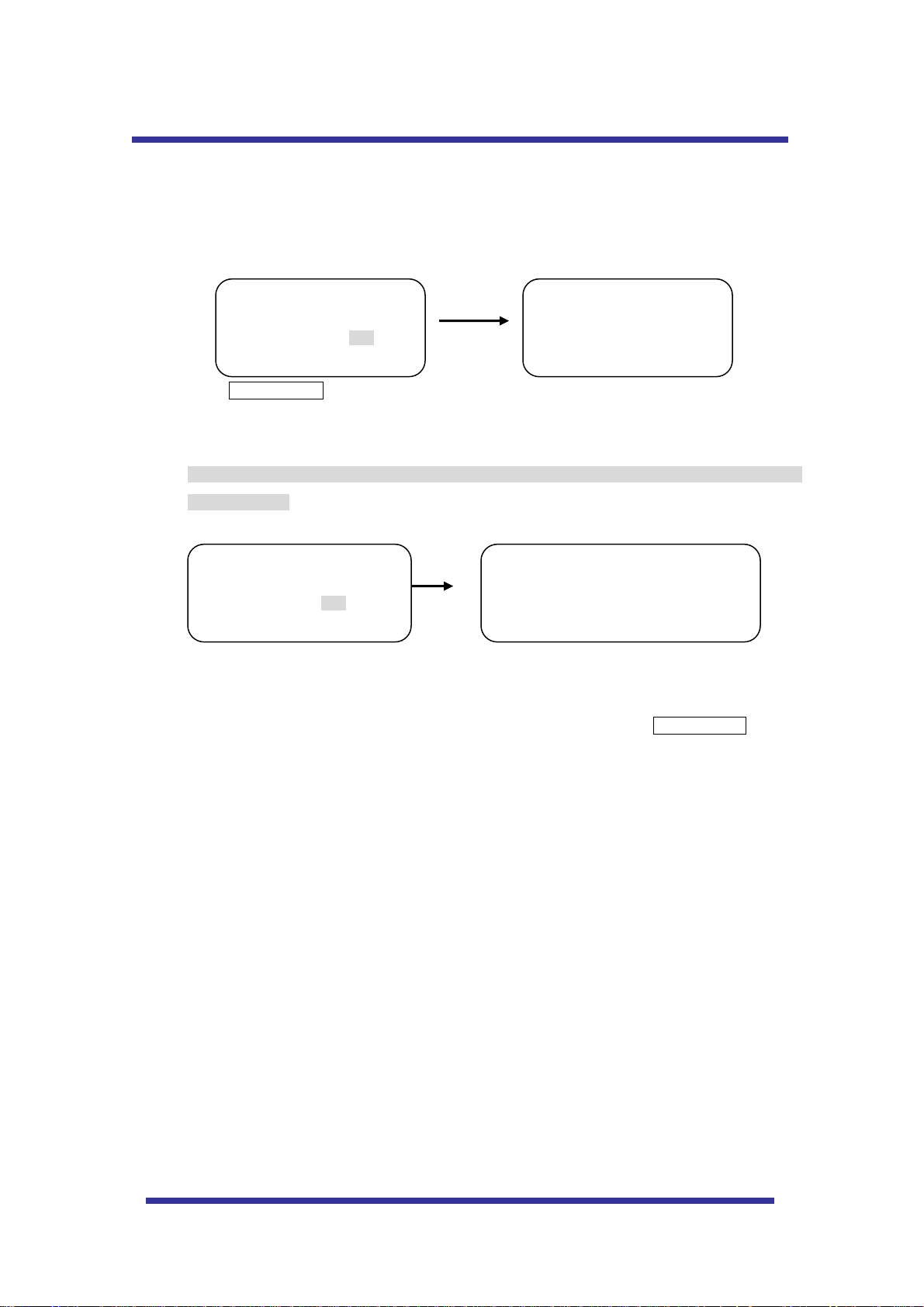
DIAGNOSTIC
When the Power is turned on a DIAGONOSTIC is operated.
The following messages are displayed on the monitor.
CAMERA ID : 001
BAUD RATE : 2400 BPS
WAITING………
PAN ORIGIN CHECK OK
TILT ORIGIN CHECK OK
TX CONNECTION TEST OK
CAMERA COMM TEST OK
A. Pan Origin Test
Zero point of Pan is founded after Panning test.
B. Tilt Origin Test
Zero point of Tilt is founded after Tilting test.
C. TX connection Test
Countdown from 60 seconds for TX Connection Test,
During the 60 seconds the camera must receive a signal from any keys of controller or DVR.
When received the correct signal, OK is displayed after TX CONNECTION TEST.
* If “Not Tested” is displayed on the monitor,
- Camera did not receive the any signal.
- Camera did receive the signal but it was not correct.
- User should check protocol, baud rate and RS-485 connection.
D. Camera Comm. Test
Communication test with the camera is automatically checked.
OK should be displayed in these four tests before installation.
If all the above Tests are OK, “EEPROM CHECKING” and “EEPROM OK” is displayed and the camera is
ready to operate.
9
Page 10
OSD MENU SETTING
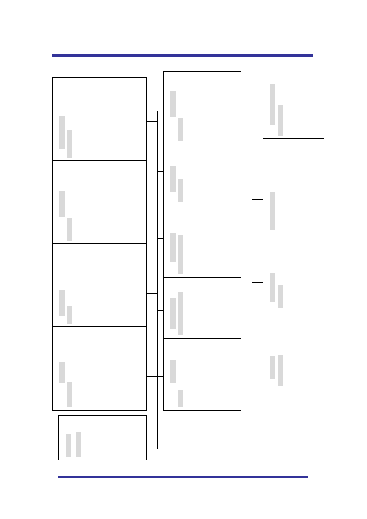
A. OSD MENU TABLE
AUTO SCAN SET
START ANGLE : XXX.X.XX.X
PRESET SET
PRESET NO: 001
CAMERA SET
FLICKER : OFF/ON
END ANGLE : XXX.X.XX.X
DIRECTION : CW
ENDLESS : OFF/ON
SPEED : QUICK
DWELL TIME : 03
PRESET ID: PRESET01□□□□□□□□□
PAN:XXX.X.XX.X TILT:XXX.X.XX.X
SAVE
EXIT
MIRROR : OFF/ON
D ZOOM : OFF/ON
WB MODE : AWB MODE
PIC FLIP : OFF/ON
BLC : OFF/ON
SAVE AND EXIT
EXIT
D/N MODE : AUTO
DSS MODE : OFF/ON
EXIT
SECTOR SET
SECTOR NO : 01
SECTOR ID : SECTOR01□□□
SECTOR START: XXX.X.XX.X
ALARM SET
ALARM NO. : 01
ALARM INPUT : OFF
ALARM ACT : 01
PATTERN SET
PATT NO. : 01
PATT TITLE PATTERN01□□□
DATA FILL : 100%
PRIVACY SET
PRIVACY NO. : 01
DISPLAY
ACTION
SECTOR END : XXX.X.XX.X
SAVE
EXIT
SAVE
EXIT
SAVE
EXIT
SAVE
EXIT
[INITIALIZATION]
[TOUR CLEAR]
[PRESET CLEAR]
[SECTOR CLEAR]
[PRIVACY CLEAR]
[PATTERN CLEAR]
[LOAD OPTIMIZED DEFAULT
[SYSTEM STATUS]
PROTOCOL : PELCO D,P
BAUD RATE: 2400BPS
FIRMWARE VER.:2.00
UPGRADED DATE: 06.28,06
CAMERA MODULE: SDM100
[PREVIOUS PAGE]
OSD DISPLAY
CAMERA ID: OFF/ON
PRESET ID: OFF/ON
SECTOR ID: OFF ON
COORDINATE:ON/OFF
[PREVIOUS PAGE]
DOME SET
CAMERA ID : CAM1□□□□□□□□□□□□
RECOVER : OFF
MAIN MENU
DOME SETUP
SPEED : FAST
MANUAL SPEED : 100°/S
AUTO FLIP : OFF
ZOOM
CAMERA SET
AUTO SCAN
TOUR
ALARM : DISABLE
LANGUAGE : ENGLISH
PRAVACY
PATTERN
[NEXT PAGE]
SAVE AND EXIT
ALARM
SECTOR
EXIT
TOUR SET
NEXT PAGE
[OSD DISPLY]
[SYSTEM STATUS]
[INITIALIZATION]
[PREVIOUS PAGE]
TOUR NO. : 01
TOUR TITLE : TOUR01□□□□□□
TOUR STEP : 01
PRESET NO : 01
DWELL TIME : 10
SPEED : 200°/S
SAVE AND EXIT
EXIT
10
Page 11
OSD MENU SETTING
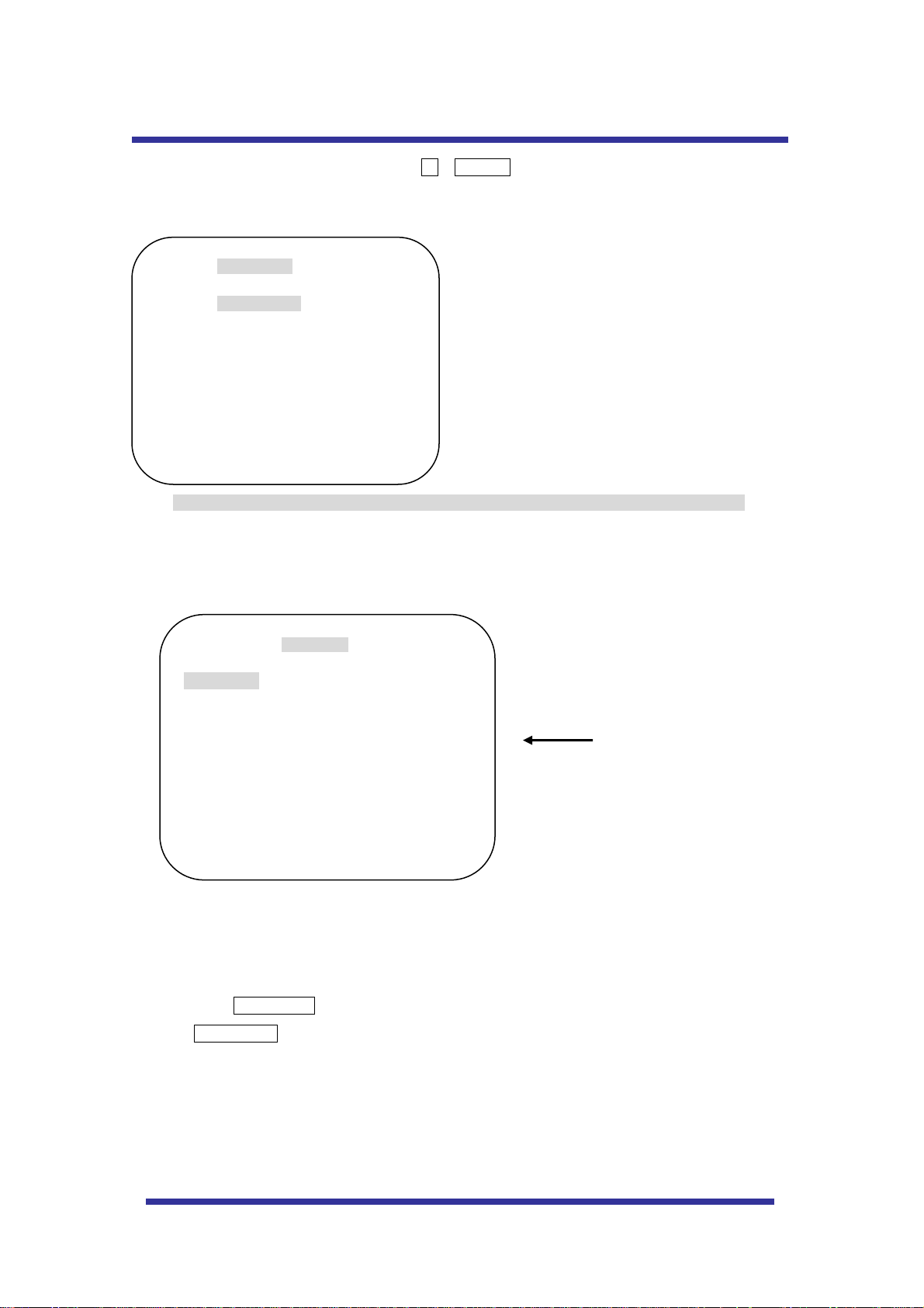
To enter the OSD Menu, press the button 95 + PRESET.
MAIN MENU
DOME SETUP
CAMERA SET
AUTO SCAN
TOUR
PRAVACY
PATTERN
ALARM
SECTOR
EXIT
* Use the joystick “up - down” to move the position and “left - right” to make selection
B. Dome Setup
To enter the Dome setup, move the joystick right to move the cursor.
DOME SET
CAMERA ID : CAM1□□□□□□□□□□□□
RECOVER : OFF
MANUAL SPEED : 100°/S
AUTO FLIP : OFF
ZOOM SPEED : FAST
ALARM : DISABLE
LANGUAGE : ENGLISH
[NEXT PAGE]
SAVE AND EXIT
EXIT
DEFAULT SETTING
B-1. DOME SET - CAMERA ID
To set camera ID, select up to 16 characters using Joystick left or right.
Press ZOOM TELE button to move to the next character from left to right direction and
ZOOM WIDE button to move to the next character from right to left direction
(Space displays when appears)
11
Page 12

OSD MENU SETTING
B-2. DOME SET - RECOVER
This feature allows the dome to work from the last setting before you use the dome manually
(Auto scan, group tour, pattern or sectors) , after the set time, even power shut down and it turns
on again. Recovery time can be programmed from 15 second to 90 seconds. The default
setting is OFF.
B-3. DOME SET - MANUAL SPEED
Manual Speed of Pan/Tilt is selectable from 10°/sec up to 200°/sec. The default setting is
100°/sec
B-4. DOME SET - AUTO FLIP
Auto Flip is available and the default setting is OFF. Move joystick “right or left” to select ON or
OFF. The default setting is OFF. This function can be recalled by pushing 67+ preset button.
B-5. DOME SET – ZOOM SPEED
Zoom speeds are selectable FAST or SLOW mode. Move joystick to the right direction for
selecting FAST or SLOW. The default setting is FAST.
B-6. DOME SET – ALARM
All alarms are available when set to the ENABLE Mode. Move joystick in the right or left direction
to select ENABLE/DISABLE. The default setting is DISABLE. This function can be recalled by
pushing 97 + preset button.
B-7. DOME SET - LANGUAGE
Multiple languages are selectable here. Move the joystick to the right or left direction to select a
language. The default setting is ENGLISH.
B-8. DOME SET – [NEXT PAGE]
DOME SET
SYSTEM LOCK: : OFF
[PASS WORD]
[OSD DISPLAY]
[SYSTEM STATUS]
[INITIALIZATION]
[PREVIOUS PAGE]
DEFAULT SETTING
B-8-1. DOME SET – [NEXT PAGE] – SYSTEM LOCK
Password protection maintains memorized data. It cannot be adjusted by anybody without the
correct password. In order to enter [PASSWORD] page, system lock status is must set as ON.
Move joystick to right or left direction to select ON. The default setting is OFF.
12
Page 13

OSD MENU SETTING
B-8-2. DOME SET – [NEXT PAGE] – [PASSWORD]
To enter this page to set a password, move the joystick to the right direction. The password must be
set by preset number from 001 to 255 (Default 99)
A. OSD MAIN MENU TABLE (PAGE 11) The default setting is BLANK.
ENTER PASSWORD
BY ENTERING PRESET CODE
PASSWORD ***
CONFIRM ***
Press any number from 001~255 with the preset button on password blank and again to confirm.
Then “CONFIRMED” is displayed on the monitor and the menu will go back to the previous page
automatically.
ENTER PASSWORD
BY ENTERING PRESET CODE
PASSWORD ***
CONFIRM ***CONFIRMED
ENTER PASSWORD
BY ENTERING PRESET CODE
PASSWORD ***
CONFIRM ***CANCELLED
<CONFIRMED> <CANCELLED>
If the user presses the wrong preset number between PASSWORD and CONFIRM, “CANCELLED”
is displayed on the monitor and if user fails 3 times, the menu will return to the previous page
automatically * After setting a Password, an operator must press memorize password in order to
enter OSD MAIN MENU, or to change the data which is memorized originally.
* An operator must remember the password for the operation. Manufacturer doesn’t provide a
memorized password.
B-8-3. DOME SET – [NEXT PAGE] – [OSD DISPLAY]
OSD ID is displayed if set ON here. Move the joystick to the right or left direction in order to select
OFF/ON when the cursor is located each item.
13
Page 14

OSD MENU SETTING
OSD DISPLAY
CAMERA ID : OFF
PRESET ID : OFF
SECTOR ID : OFF
COORDINATE : ON
[PREVIOUS PAGE]
B-8-4. DOME SET – [NEXT PAGE] – [SYSTEM ST ATUS]
This page shows the information of this camera.
PROTOCOL : PELCO D, P
BAUD RATE : 2400 BPS
FIRMWARE VER. : 2.00
UPGRADED DATE : 06.07,22
CAMERA MODULE : SDM100
[PREVIOUS PAGE]
SYSTEM STATUS
DEFAULT SETTING
DEFAULT SETTING
- Protocol and baud rate are shown according to the dip switch setting
(Refer to page 29, 30 and 31)
- Firmware version and upgraded date will be changed if upgraded.
B-8-5. DOME SET – [NEXT PAGE] – [INITIALIZATION]
To clear all memorized data for tour, preset, sector, privacy or pattern, move joystick to the right
direction when the cursor is on [INITIALIZATION]
[TOUR CLEAR]
[PRESET CLEAR]
[SECTOR CLEAR]
[PRIVACY CLEAR]
[PATTERN CLEAR]
[LOAD OPTIMIZED DEFAULT]
[PREVIOUS PAGE]
INITIALIZATION
14
Page 15
OSD MENU SETTING
- To clear memorized data, move joystick to the right direction when cursor is on each
item.
TOUR CLEAR
ARE YOU SURE? YES NO
Press FOCUS NEAR button when the cursor is at YES in order to clear memorized data. Then
each item such as tour, preset, sector and so on is displayed on the monitor about 2~3 seconds.
After this process, the menu is returned to the previous page.
* [PRESET CLEAR], [SECTOR CLEAR], [PRIVACY CLEAR], [PATTERN CLEAR] are same as
[TOUR CLEAR].
TOUR CLEAR
LOAD OPTIMIZED DEFAULT
ARE YOU SURE? YES NO
- To clear all data and return to factory defaults, move the joystick to the right when the cursor is at
[LOAD OPTIMIZED DEFAULT] to enter the above page.
- Move the joystick to the right or left direction in order to select YES, press FOCUS NEAR button.
- Then “ALL DATA INITIALIZING” is displayed about 5~7 seconds and then the menu is returned to
the previous page automatically.
B-9. DOME SET – [NEXT PAGE] – SAVE AND EXIT
To save the memorized data and escape this page, move the joystick to the right when
the cursor is at SAVE AND EXIT.
B-10. DOME SET – [NEXT PAGE] – EXIT
In order not to save any data and escape this page, move the joystick to the right when
ALL DATA INITIALIZING
the cursor is at EXIT
15
Page 16

OSD MENU SETTING
C. CAMERA SET
FLICKER : OFF
MIRROR : OFF
APERTURE : 10
D ZOOM : OFF
WB MODE : AWB MODE
PIC FLIP : OFF
BLC : OFF
D/N MODE : AUTO
DSS MODE : OFF
EXIT
C-1. CAMERA SET - FLICKERLESS
Flickerless feature is selected between 50Hz and 60Hz. The default setting is OFF (NTSC: 60Hz /
PAL: 50Hz). Set flicker mode ON when power source is in discord with frequency. The default
setting is OFF
C-2. CAMERA SET - MIRROR
This feature creates a mirror image. The default setting is OFF.
CAMERA SET
C-3. CAMERA SET – APERTURE
Aperture enhances picture details and sharpness by increasing the gain of the camera and
sharpening the edges in the picture. The default seeting is 10. (the aperture level is from 00 ~ 15)
C-4. CAMERA SET – D ZOOM
Move the joystick to the right in order to set as ON. The default setting is OFF.
C-5. CAMERA SET – WB MODE
White balance functions have 4 modes according to the condition of the lighting. The default setting
is AWB and it may change the mode option accoding to the lighting conditions as below.
AWB Mode – 3,200°K to 6, 000°K
z Indoor – up to 3,200°K
z Outdoor – up to 5,800°K
z ATW Mode - 2,000°K to 10, 000°K
16
Page 17

OSD MENU SETTING
C-6. CAMERA SET – PIC FLIP
Picture flip feature turns ths picture upside down. Move the joystick to the right or left direction to
select OFF/ON. The default setting is OFF.
C-7. CAMERA SET – BLC (Back Light Compensation)
The default setting is OFF and BLC modes can be OFF/ON.
OFF – Backlight compensation is not activated.
ON – Back light compensation is activated.
This function can be recalled by pushing 93 + preset button.
C-8. CAMERA SET – D/N MODE
ICR filter is changeable according to the lighting, AUTO – NIGHT MODE – DAY MODE.
The default setting is AUTO MODE. This function can be recalled by pushing 94 + preset button.
C-9. CAMERA SET – DSS MODE (DIGITAL SLOW SHUTTER)
If DSS is turned on the digital slow shutter is working. The DSS will remain open to receive some
more lighting.
The default setting is OFF.
C-10. CAMERA SET – EXIT
To escape this page, move the joystick to the right direction.
17
Page 18

OSD MENU SETTING
D. PRESET SET
To enter PRESET SET, move the joystick to the right direction.
PRESET NO :001
PRESET ID :PRESET001------PAN :XXX.XX TILT : XXX.XX
SAVE
EXIT
PRESET SET
D-1. PRESET – PRESET NO.
Up to 164 numbers of preset positions are available. Move joystick to the right or left direction to
select a preset no.
D-2. PRESET – PRESET ID
To set preset ID, select up to 16 characters using Joystick to the left or right.
Press ZOOM TELE button moves to the next character from the left to the right direction and
ZOOM WIDE button moves to the next character from the right to left direction
(Space displays when appears)
DEFAULT SETTING
D-3. PRESET – P AN: XXX.X TILT: XX.X
Press FOCUS FAR button in order to set the preset position, then use the joystick to move the
camera to the position where the memorized preset no. is needed. Then press FOCUS FAR button
again after setting a preset location.
D-4. PRESET – SAVE
Move the joystick to the right when the cursor is at SAVE and then the cursor will be located on the
Preset ID for the continuous preset No. setting.
D-5. PRESET – EXIT
To escape this page, move joystick to the right .
18
Page 19

OSD MENU SETTING
E. AUTO SCAN SET
* 66 + preset button is working as AUTO SCAN after setting.
START ANGLE : XXX.X.XX.X
END ANGLE : XXX.X.XX.X
DIRECTION : CW
ENDLES : OFF
SPEED : 10°/S
DWELL TIME : 03
SAVE AND EXIT
EXIT
E-1. AUTO SCAN – START ANGLE
To set the start angle, press FOCUS FAR button then move the joystick to the starting angle which is
AUTO SCAN SET
DEFAULT SETTING
to be memorized. Press FOCUS FAR button again is to escape.
E-2. AUTO SCAN – END ANGLE
To set end angle, press FOCUS FAR button then move the joystick to the starting angle which is to
be memorized. Press FOCUS FAR button again is to escape.
E-3. AUTO SCAN – DIRECTION
Auto Scan directions are available with two direction as CW or CCW by joystick to the right or left
direction
CW: Clock wise direction (Default)
CCW: Count Clock Wise Direction.
E-4. AUTO SCAN – ENDLESS
Auto Scan can use endless rotation, move joystick to the right direction in order to select ON.
Otherwise, the default setting is OFF.
E-5. AUTO SCAN – SPEED
User can use auto scan speed from 01°/S up to 99°/S and the default setting is 10°/S.
E-6. AUTO SCAN – DWELL TIME
To select dwell time, move joystick to the left or right direction in order to adjust dwell time. It is
possible to set from 01 second to 99 seconds and the default setting is 03 seconds.
E-7. AUTO SCAN – SAVE AND EXIT
To saving the memorized data and escape this page, move the joystick to the right when
the cursor is at SAVE AND EXIT.
E-8. AUTO SCAN – EXIT
To escape this page, move the joystick to the right .
19
Page 20

OSD MENU SETTING
F. TOUR SET
8 Programmable tours can be set and each tour is available to set up to 64 preset steps. After setting
the data to each tour group, 71~78 + preset buttons are working as group tour # 1~8
TOUR NO : 01
TOUR TITLE : TOUR01□□□□□□□□□□
TOUR STEP : 01
PRESET NO. : 01
DWELL TIME : 03
SPEED : 200°/S
SAVE
EXIT
F-1. TOUR SET – TOUR NO.
Max. 8 group tour no. set by the joystick are available.
TOUR SET
DEFAULT SETTING
F-2. TOUR SET – TOUR TITLE
To set the tour title, select up to 16 characters using Joystick to left or right.
Press ZOOM TELE button to move the next character from the left to the right and ZOOM WIDE
button to move the next character from the right to left direction (Space displays when appears)
The tour title is not displayed on the monitor, but only for the reference of user.
F-3. TOUR SET – TOUR STEP
Each tour group consists of up to 60 preset steps with different dwell time and speed. It is possible
to match any preset # for each tour step.
F-4. TOUR SET – PRESET NO.
The chosen tour step #101 ~200. It is possible to select any preset no. up to
164.
F-5. TOUR SET – DWELL TIME
Dwell time can be up to 99 seconds from 01 second. The default setting is 03 seconds.
F-6. TOUR SET – SPEED
Each tour step can be set with different tour speed up to 200°/S and it is selectable from 10°/S.
Move joystick to the right or left to select the tour speed. The default setting is 200°/S.
F-7. TOUR SET – SAVE
To save the memorized data and escape this page, move the joystick to the right when the
cursor is at SAVE
F-8. TOUR SET – EXIT
To escape this page, move the joystick to the right
20
Page 21

OSD MENU SETTING
G. PRIVACY SET
4 Privacy masking zones are available to block out areas of the scene.
PRIVACY NOMBER : 01
DISPLAY : OFF
ACTION : MOVE
SAVE
EXIT
G-1. PRIVACY SET – PRIVACY NUMBER.
Up to 4 privacy masking zones are available.
PRIVACY SET
DEFAULT SETTING
G-2. PRIVACY SET – DISPLAY.
Move joystick to the right or left direction to set ON in order to show the selectable block in the
center of the monitor. This block appears as a translucent blue square when turned ON. The
default setting is OFF.
G-3. PRIVACY SET – ACTION (MOVE / ADJUST)
To set the privacy area, press FOCUS FAR button when the MOVE MODE is showing. Then use
the joystick to the user defined area in order to set the privacy zone. Then press FOCUS FAR
button again to escape from MOVE MODE.
To adjust size of the privacy zone, move the joystick to the right or left direction when the cursor is
on ACTION. After move mode changed to ADJUST MODE, press FOCUS FAR button in order to
adjust the size of the privacy zone. The size of he privacy zone can be adjusted by using the
joystick up down or left right,. After adjusting size of the privacy zone, press FOCUS FAR button to
escape ADJUST mode.
z ADJUST: You can change the masking size by using the joystick to the left or right direction
z MOVE: You can move the privacy zone by using joystick to the left or right direction
G-4. PRIVACY SET – SAVE
After setting the privacy masking zone, to save the data, move the joystick to the right direction
when the cursor is on SAVE. After saving the data, the cursor moves to PRIVACY NO.2
automatically to prepare the next privacy masking zone.
G-5. PRIVACY SET –EXIT
To escape this page, move the joystick to the right
21
Page 22

OSD MENU SETTING
H. PATTERN SET
8 programmable patterns are available with 16 characters of title.
After setting the data to each pattern # 1~8, 81~88+ preset buttons are working as Pattern # 1~8.
PATT NO : 01
PATT TITLE: PATTERN01□□□□□□□
DATA FILL : 0%
SAVE
EXIT
H-1. PATTERN SET –PATT NO.
Up to 8 programmable user-defined patterns set by the joystick are available.
PATTERN SET
DEFAULT SETTING
H-2. PATTERN SET –PATT TITLE
To set PATTERN TITLE, select up to 16 characters using Joystick to the left or right.
Press ZOOM TELE button moves to the next character from the left to the right direction and
ZOOM WIDE button moves to the next character from the right to left direction (Space displays
when appears) Pattern title is not displayed on the monitor, but only for the reference of user.
H-3. PATTERN SET –DATA FILL
To fill the programming data, press FOCUS FAR button in order to start the data fill up. Filling data
is programmed according to the joystick movement. Press FOCUS FAR button again in order to
escape.
H-4. PATTERN SET –SAVE
To saving the memorized data, move the joystick to the right when the cursor is on SAVE. Then the
cursor moves to the PATT NO.02 in order to prepare next pattern no.
H-5. PATTERN SET –EXIT
To escape this page, move joystick to the right
22
Page 23

OSD MENU SETTING
I. ALARM SET
4 Alarm inputs are available and each alarm can activate presets, group tours or patterns.
ALARM NO : 01
ALARM INPUT: OFF
ALARM ACT : 001
SAVE
EXIT
ALARM SET
DEFAULT SETTING
I-1. ALARM SET – ALARM NO.
Up to 4 alarms are selectable by using the joystick to the right when the cursor is on ALARM NO.
I-2. ALARM SET – ALAR M INPUT
Input alarm provides two different ways - NC (Normal Close) or NO (Normal Close)
I-3. ALARM SET – ALAR M ACT
Alarm activates various surveillance modes with Preset number up to 164, Group tour up
to 8, Pattern up to 8. Move the joystick to the right or left direction to select any preset
number, group tour no. or pattern no.
I-4. ALARM SET – SAVE
After setting the alarm input parameters, to save the data, move the joystick to the right when the
cursor is on SAVE. After saving the data, the cursor moves to Alarm NO.2 automatically to prepare
the next alarm.
ALARM SET –EXIT
I-5.
To escape this page, move the joystick to the right
* Before activating an Alarm, user must set ALARM ENABLE at DOME SET – ALARM – ENABLE
(Refer to page 15)
23
Page 24

OSD MENU SETTING
J. SECTOR SET
Up to 8 programmable sectors are available with 16 characters.
This feature is useful to memorize certain locations such as a parking zone, etc.
When a camera goes through this area, it shows the letter you memorized.
SECTOR NO : 01
SECTOR ID: SECTOR01□□□□□□□□
SECTOR START: XXX.X.XX.X
SECTOR END : XXX.X.XX.X
SAVE
EXIT
J-1. SECTOR SET – SECTOR NO.
SECTOR SET
DEFAULT SETTING
Up to 8 programmable sectors set by the joystick are available.
Start Position
End Position
J-2. SECTOR SET – SECTOR ID
To set SECTOR ID, select up to 16 characters by using the Joystick to the left or right.
Press ZOOM TELE button to move to the next character from the left to the right direction and
ZOOM WIDE button to move to the next character from the right to left direction (Space displays
when appears)
J-3. SECTOR SET – SECTOR START
To set SECTOR START angle, press FOCUS FAR button then move joystick to the left or right
direction to set the position. To press FOCUS FAR button again is to escape.
J-4. SECTOR SET – SECTOR END
To set SECTOR END angle, press FOCUS FAR button then move joystick to the left or right
direction to set the position. To press FOCUS FAR button again is to escape.
J-5. SECTOR SET – SAVE
After setting the SECTOR position, to save the data, move the joystick to the right when the cursor
is on SAVE. After saving the data, the cursor moves to SECTOR NO.2 automatically to prepare the
next SECTOR.
J-6. SECTOR SET –EXIT
To escape this page, move the joystick to the right
K. EXIT
To escape the OSD Main Menu, move the joystick to the right or left direction then this
camera is ready to operate.
24
Page 25

DIP SWITCH SETTING
A-1. DIP SW SETTING
This Speed Dome camera provides up to 63 camera ID’s, adjustable using the 1st~6th Dip switch.
Open the camera case to set ID using DIP SW1.
* Factory default: Camera ID = 1, PELCO-D
A-2. ID SETTING
DIP SW ID VALUE DIP SW ID VALUE DIP SW ID VALUE
100000XXXX 1 111010XXXX 23 101101XXXX 45
010000XXXX 2 000110XXXX 24 011101XXXX 46
110000XXXX 3 100110XXXX 25 111101XXXX 47
001000XXXX 4 010110XXXX 26 100011XXXX 48
101000XXXX 5 110110XXXX 27 100011XXXX 49
011000XXXX 6 001110XXXX 28 010011XXXX 50
111000XXXX 7 101110XXXX 29 110011XXXX 51
000100XXXX 8 011110XXXX 30 001011XXXX 52
100100XXXX 9 111110XXXX 31 101011XXXX 53
010100XXXX 10 000001XXXX 32 011011XXXX 54
110100XXXX 11 100001XXXX 33 111011XXXX 55
001100XXXX 12 010001XXXX 34 000111XXXX 56
101100XXXX 13 110001XXXX 35 100111XXXX 57
011100XXXX 14 001001XXXX 36 010111XXXX 58
111100XXXX 15 101001XXXX 37 110111XXXX 59
000010XXXX 16 011001XXXX 38 001111XXXX 60
100010XXXX 17 111001XXXX 39 101111XXXX 61
010010XXXX 18 000101XXXX 40 011111XXXX 62
110010XXXX 19 100101XXXX 41 111111XXXX 63
001010XXXX
101010XXXX 21 110101XXXX 43
011010XXXX
(1-ON, 0-OFF) (1Î10)
20
22
010101XXXX
001101XXXX
42
44
Termination
Baud rate
Protocol
ID Set
25
Page 26
DIP SWITCH SETTING
A-3. PROTOCOL
7th~8th dip switches are used for Protocol Setting.
Factory Default: Pelco-D or Pelco-P ( Auto detection)
DIP SW1- 7 DIP SW1- 8
OFF OFF Pelco-D or Pelco-P
A-4. BAUD RATE SETTING
The 9th Dip Switch is used for BAUD RATE setting.
DIP SW can be changeable to 2400bps, 9600bps.
Factory Default: 2400bps.
DIP SW1 9th BAUD RATE
OFF 2400
ON 9600
.
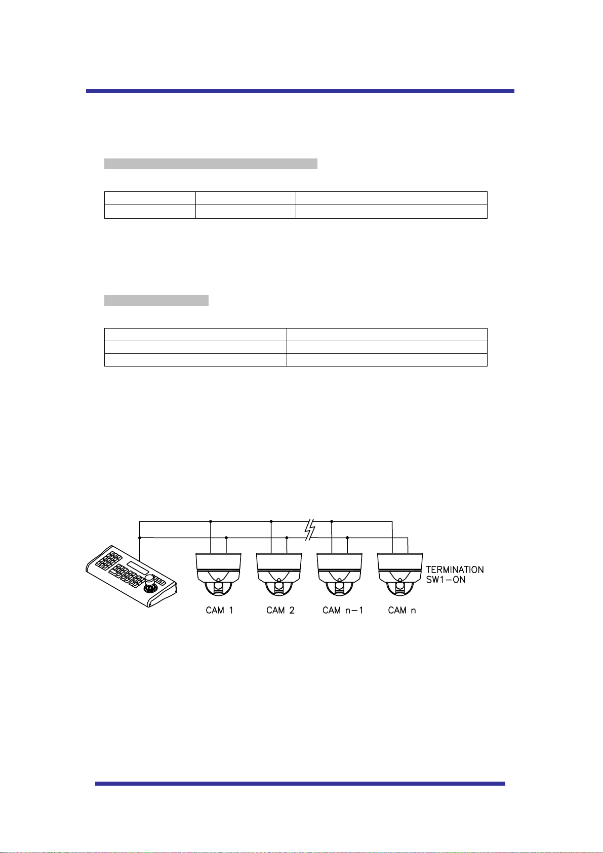
A-5. 485 TERMINATIONS
10th Dip Switch is used for 100Ω termination.
Set on 10th Dip Switch only for the last looped camera from the controller.
Even in case of only one camera, set on 10th Dip Switch of the cameras.
26
Page 27

a
TROUBLE SHOOTING
If you have trouble operating in your camera, refer to the following.
PROBLEM
Check if the power supply is 12 VDC.
Not operating
No picture
Dark screen Adjust the monitor.
Check if RS-485 communication cable is connected correctly.
Check camera ID setting.
Check the termination.
Check if all the cables are connected correctly.
Check if the monitor is adjusted correctly.
Check if video signal line is cut.
SOLUTION
Abnormal camera
Operation
Screen not clear
Check if voltage level is out of the specification.
Check the termination.
Check if there is dust on the lens.
Adjust the monitor.
If excessive light is seen on a screen, change the camer
angle or location.
Adjust the lens focus again.
27
Page 28

SPECIFICATIONS
MODEL
PAN /TILT
FUNCTIONS
POWER
OTHERS
CAMERA
MODULE
Pan Rotation Angle 360˚ Endless
Pan Speed
Tilt Rotation Angle 0˚ ~ 90˚
Tilt Speed
System Accuracy 0.02˚
Presets
Group Tour
Auto scan Programmable Auto scan
Pattern 8 Programmable Patterns (total 400 seconds)
Privacy Zone 4 privacy zones
Sector 8 selectable Sectors with 16 characters
Password Protection Yes
Alarm Input 4 alarms OFF/NC/NO (with various programmable states)
Alarm Actions Activate preset, Group scanning or Patterns
Auto Flip ON / OFF
OSD Menu Multiple Languages on screen
Communication RS-485
Protocol Pelco D/P
Power Consumption 9W Max
Power Supply 12VDC 750mA
Construction Die-cast , Anti-vandal dome cover
Dimensions 167.0φ (D) * 167.0mm(H)
Weight 1.5 kg
Motor Type Stepper Motor
Micro Steps 1/4 Step
Storage Temperature -40F to +140F
Operating Temperature -14F to +120F
Certifications CE, FCC
Image Sensor 1/4" Sony Super HAD CCD
Total
Image
Pixels
Number Of
Effective
Pixels
Horizontal resolution More Than 500TV Lines
Lens
Day & Night (ICR) Auto/ Day/ Night
Min. Shooting Distance 0.35m(Wide)/0.8m(Tele)
Digital Slow Shutter 2/4/8/16/24/32/64/128/ OFF
Min.
illumination
Luminance S/N Ratio More than 50dB
Video Output VBS:1.0Vp-p/75 Ohm
BLC ON / OFF
Flickerless
WHITE BALANCE AWB/ATW/INDOOR/ OUTDOOR
Manual 10˚ ~ 200˚/sec
Preset Max 200˚ /sec
Manual 10˚ ~ 200˚/sec
Preset Max 200˚ /sec
NTSC 811(H) * 508(V) 410K
PAL 795(H) * 596(V) 470K
NTSC 768(H) * 494(V) 380K
PAL 752(H) * 582(V) 440K
Optical
Digital 10x (100x with optical)
Normal
mode
Night
mode
NTSC ON / OFF (1/100)
PAL ON / OFF (1/120)
HTSD10X
164 positions with a 16-character label available for each position
with different speed steps
Max. 8 Programmable group tours (each one consisting of up to 60 preset steps
with different steps)
10x Optical Zoom
(F=3.8 to 38mm)
0.7Lux (50IRE)
0.02Lux (ICR On)
28
Page 29
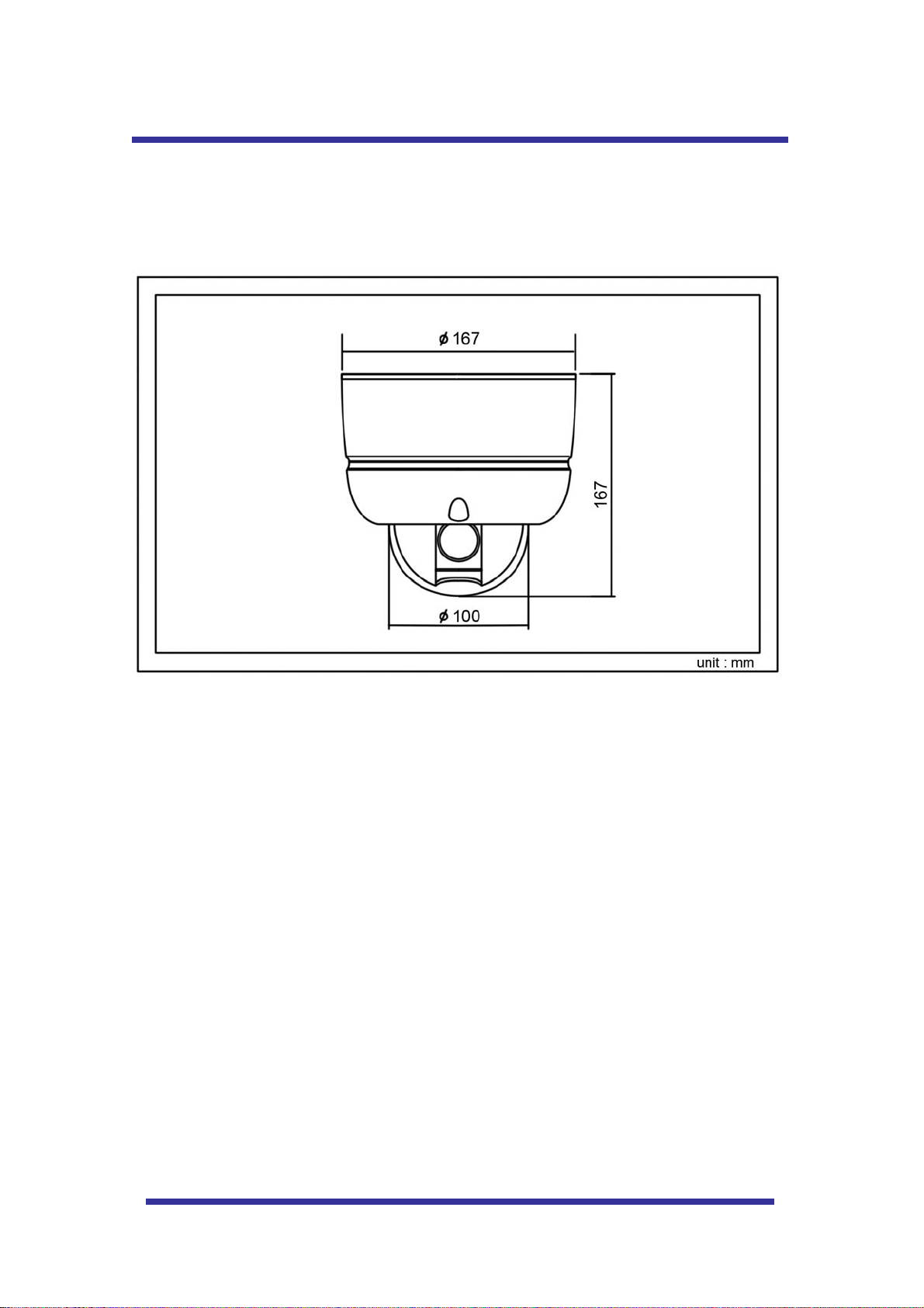
DIMENSIONS
29
Page 30

MEMO
30
Page 31
31
Page 32

Speco Technologies is constantly developing product improvements.
We reserve the right to modify product design and specifications without notice
and without incurring any obligation.
Rev.100125
32
 Loading...