

Page 1

DVR-PC8/16 Series
User Manual
Includes setup, usage, and troubleshooting information for your DVR
©2007 SPECO TECHNOLOGIES
All rights reserved under the copyright laws.
First Edition MAY. 1
P.O.Box 726, 200 New Highway, Amityville, NY 11701-0726, United States of America
Customer Service: TEL : 631. 957. 8700 FAX : 631. 957. 9142
Important: Read all the installation instructions carefully before you plug your DVR into a wall socket.
st
, 2007.
Page 2

2
Warning
Electric Safety
To reduce risk of fire or electrical shock,
Do not expose this product to rain or any moisture.
Caution
Install the battery correctly to avoid risk of an explosion.
Align the battery properly and use only the same type of batteries
as recommended by manufacturer
Dispose of used batteries according to the manufacturer’s instructions.
Page 3

3
Cautions
Read all of the instructions and safety information before you plug your DVR into a wall socket.
Signs of Caution and Warning
Warning: This sign indicates that the user could die or wounded seriously if not used or installed properly.
Caution: This sign indicates that the user could be wounded or could expect property damage if not used
How to handle lithium battery
Warning
1. Change the battery after disconnecting the power plug of the product.
2. Connect the polarity of the lithium properly while changing.
3. Change with the same type of battery recommended by the product manufacturer.
4. Follow the instruction from battery manufacturer to change the battery.
It is important that safety instructions marked on the product and in the documentation are followed.※
Important Safeguards
Warning
1. Use the power cord that came with your DVR or recommended by the supplier.
This may cause fire.
2. Do not dismantle or assemble the product.
This may cause malfunction or fire.
3. Do not touch the product with wet hands.
This may become a reason for malfunction or fire.
4. Inquire from the place of purchase if the need for installation in distinct place arises.
Delinquent installation may be the reason for malfunction, electric shock or fire.
5. Ground applies to video products equipped with a 3-wire grounding type plug having a third (grounding) pin.
This plug only fits into a grounding-type power outlet.
If grounding is not done, this may cause break down or electric shock.
6. Ground connection must not touch gas pipe, water pipe or telephone line.
If grounding is not done properly, this may cause electric shock.
7. Prevent metallic foreign substance from going inside the product.
This may become a reason for malfunction or electric shock.
8. Prevent water from entering inside electrical parts.
Clean with a dry tower otherwise this may become a reason for malfunction or electric shock.
Caution
1. Do not drop or give shock to the product.
It may become a reason for malfunction.
2. The air inhaler of the front panel and air outlet of the back panel must not be blocked while installing.
The internal temperature of the product would be more than what is allowed and it may become a reason for malfunction
or would generate heat.
or installed properly.
Page 4

4
3. Do not touch the product or the power plug, when there is thunder.
It may become a reason for electric shock.
4. Do not install the product near or on top of heating system.
The internal temperature of the product would be more than what is allowed and it may become a reason for malfunction
or would generate heat.
5. Do not install the product on inclined or unstable location and where vibration could be committed.
It may become a reason for malfunction.
Power Management
Warning
1. Do not connect on the middle of power plug or use extension cord.
It may generate heat or cause fire.
2. Do not touch the power cord with wet hands.
It may become a reason for electric shock.
3. Prevent wetting the power plug by humidity.
It may generate heat or cause fire. The power cord is not waterproof.
4. Disconnect the power plug from the socket if you are not using the product for a long time.
It may become a reason for short-circuit or electric shock.
Caution
1. Do not disconnect the power plug by pulling it out.
To turn off the power, click the power button from the front panel.
When the system stop abnormally the power button might not work. In that case, press the power button for at least 4
seconds to turn off your DVR.
2. Do not cut off the power artificially, It may give shock or vibration while the hard disk is activating.
It may become a reason for hard disk failure or loss of data.
Page 5

5
Table of Contents
1. SYSTEM STRUCTURE ............................................................................................................................................................... 6
1.1 DVR-PC8/16 SERIES.................................................................................................................................................................... 6
2. SYSTEM CONFIGURATION..................................................................................................................................................... 7
2.1 DVR-PC8/16 SERIES FRONT PANEL ............................................................................................................................................ 7
2.2 DVR-PC8 SERIES BACK PANEL................................................................................................................................................... 8
2.3 DVR-PC16 SERIES BACK PANEL................................................................................................................................................. 8
3. INSTALLATION............................................................................................................................................................................9
3.1 DVR-PC8 SERIES INSTALLATION................................................................................................................................................. 9
3.2 DVR-PC16 SERIES INSTALLATION............................................................................................................................................. 11
4. BASIC OPERATION.................................................................................................................................................................. 12
4.1 POWER CONNECTION ................................................................................................................................................................. 12
4.2 START PROGRAM ........................................................................................................................................................................ 12
4.3 TO START RECORDING................................................................................................................................................................ 13
4.4 SEARCH RECORDED IMAGE........................................................................................................................................................ 15
5. SCREEN LAYOUT...................................................................................................................................................................... 16
5.1 MAIN SCREEN............................................................................................................................................................................. 16
5.2 VIEWER....................................................................................................................................................................................... 23
5.3 SEARCH TOOLS........................................................................................................................................................................... 29
6. SETTING CUSTOMIZED FUNCTIONS................................................................................................................................. 40
6.1 CAMERA SETTING....................................................................................................................................................................... 40
6.2 NETWORK................................................................................................................................................................................... 43
6.3 SENSOR/CONTROL...................................................................................................................................................................... 46
6.4 PTZ............................................................................................................................................................................................. 50
6.5 COLOR ........................................................................................................................................................................................ 55
6.6 DISPLAY...................................................................................................................................................................................... 56
6.7 FPS/RESOLUTION....................................................................................................................................................................... 61
6.8 SCHEDULE .................................................................................................................................................................................. 62
6.9 SYSTEM....................................................................................................................................................................................... 65
6.10 DIGITAL DETERRENT.............................................................................................................................................................. 68
7. INSTANT PLAYBACK...............................................................................................................................................................69
7.1 VCR MODE ................................................................................................................................................................................ 69
7.2 VCR PLAYBACK AND RECORD MODE ....................................................................................................................................... 71
7.3 VCR RECORD MODE.................................................................................................................................................................. 75
7.4 VCR PLAYBACK MODE.............................................................................................................................................................. 76
8. APPENDIX................................................................................................................................................................................... 77
8.1 PIN ASSIGNMENT OF ALARM PORT ............................................................................................................................................ 77
8.2 TCP/IP PORT SETTING METHOD USING THE FIREWALL............................................................................................................. 78
Page 6
6
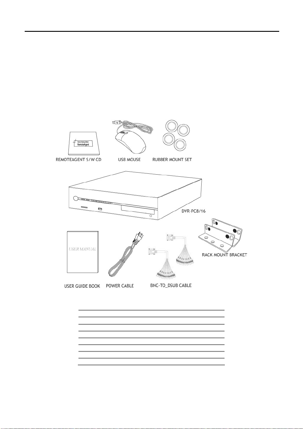
1. SYSTEM STRUCTURE
Before going any further, be sure that you have received the following items with your DVR. Components may vary
according to your model and local area.
Your DVR-PC8/16 Series DVR includes the following components. Carefully inspect each component to make sure
nothing is missing or damaged. If any of these items are missing or damaged, notify your dealer immediately. Keep
packing utilities for moving or storage purposes afterwards.
1.1 DVR-PC8/16 Series
Qty Contents
1
1 RemoteAgent CD
1 Power Cord
1 Rubber Mount
1 Mouse
2 8CH BNC-to-D-sub Cable (Select by Max Channel Number)
2 Rack Mount Bracket
User Manual
Page 7
7
2. System Configuration
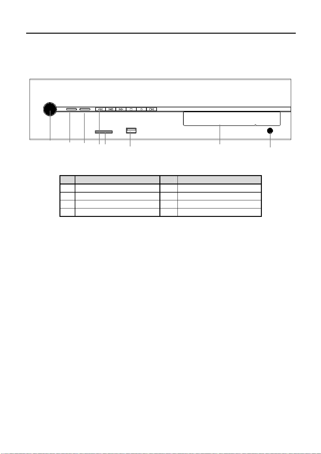
2.1 DVR-PC8/16 Series Front Panel
1 2 3 4 5 6 7 8
No. Functions No. Functions
1 Power Button & Power LED 5 SD/MMC Port
2 HDD LED 6 USB Port
3 Network LED 7 CD-RW / DVD-RW (Option)
4 Instant Playback 8 Eject Button
2.1.1. Power Button
To turn your DVR, press the power button shortly (1 second).
2.1.2. HDD LED
Shows data is either being read or written in HDD.
2.1.3. Network LED
This LED is lit when a network client(RemoteAgent) is connected to the system.
2.1.4. Instant Playback
Quick action tools for playing and recording data through various storage media.
2.1.5. SD/MMC Port
Data can be saved with either a SD or MMC card.
2.1.6. USB Port
This internal USB port is used to connect the USB to the system. USB port is composed in back panel of the system also.
2.1.7. CD-RW / DVD-RW (Option)
It is possible to mount CD-RW / DVD-RW as backup or removable HDD as data storage.
2.1.8. Eject Button
Open and eject CD-RW/DVD-RW
DVR-PC8/16
Page 8
8
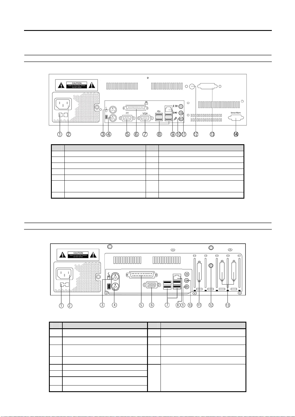
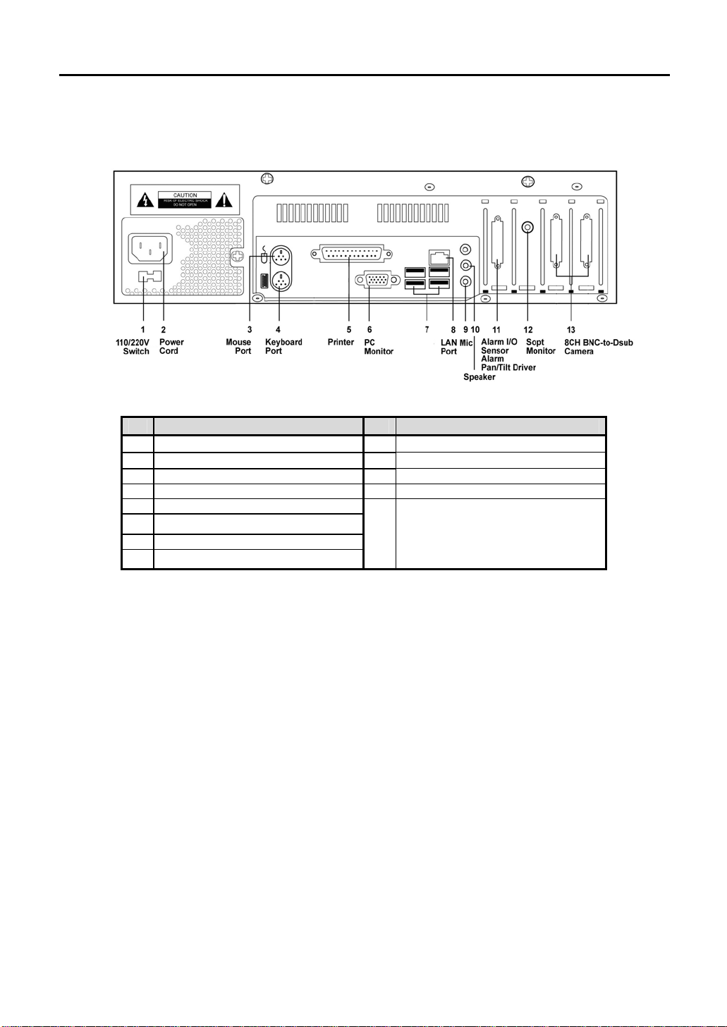
2.2 DVR-PC8 Series Back Panel
Note Composition may differ according to system model.
No. Functions No. Functions
1 Power Selection Switch 8 USB Ports
2 Power Connection Circuit 9 LAN Port
3 Mouse Port 10 MIC
4 Keyboard Port 11 Speaker Output
5 PTZ Controller Port 12 Spot Monitor Output (BNC Jack)
6 Printer Port 13
7 PC Monitor Output 14 Sensor / Alarm Connection
2.3 DVR-PC16 Series Back Panel
Note Composition differs according to system model.
Image Input/D-Sub
DVR-PC8: 8CH x 1EA
No. Functions No. Functions
1 Power Selection Switch
2 Power Connection Circuit 10 Speaker Output
3 Mouse Port 11
4 Keyboard Port 12 Spot Monitor Output (RCA Jack)
5 Printer Port
6 PC Monitor Output (VGA)
7 USB Ports
8 LAN Port
13
9
Alarm Input/Output Port/
DVR-PC16: 8CH x 2EA
MIC
PTZ Controller Port
Image Input / D-Sub
Page 9
9
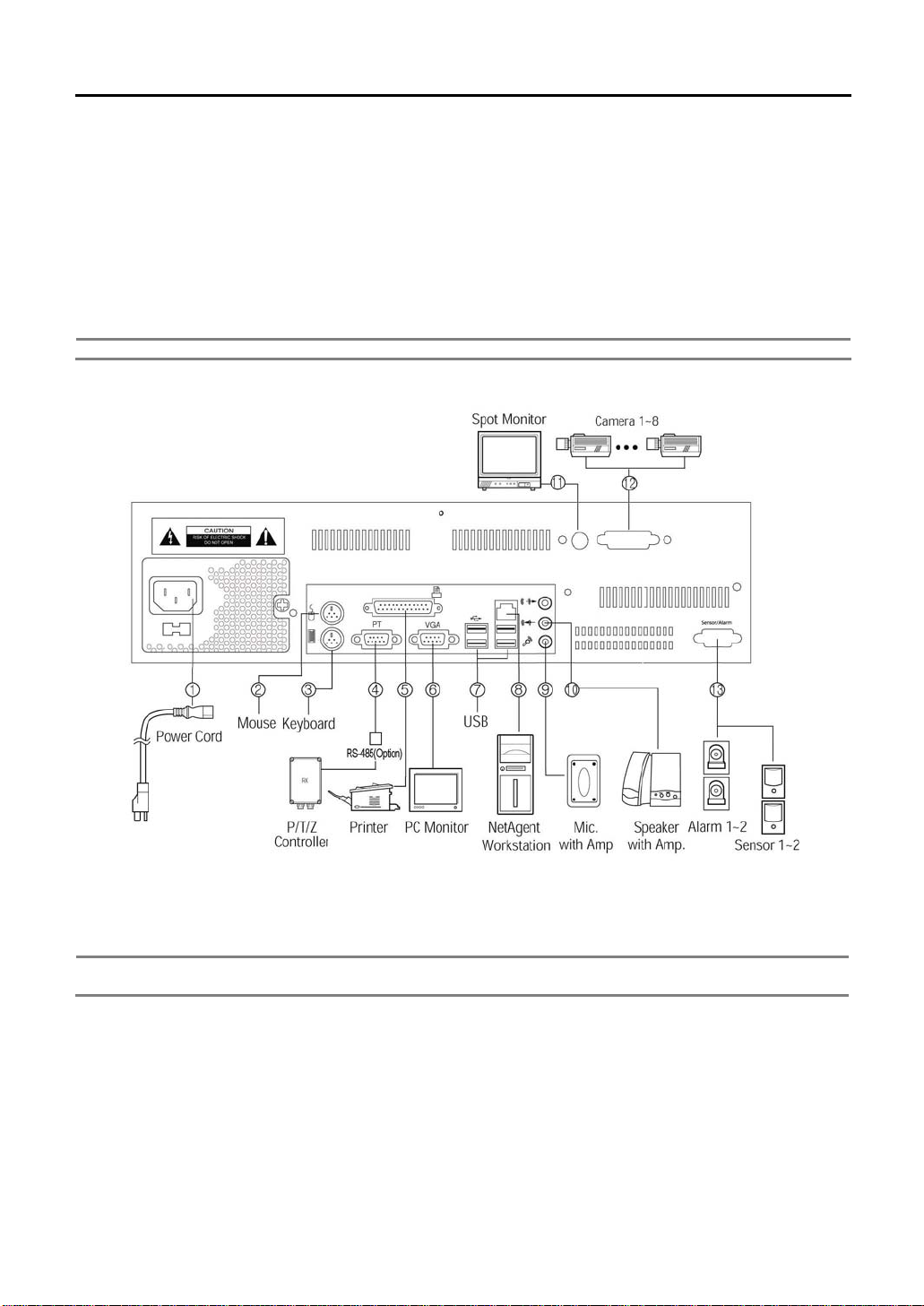
3. INSTALLATION
3.1 DVR-PC8 Series Installation
This section describes how to connect peripheral devices to DVR-PC8. Connect the peripheral devices by following
instruction as below.
(The connections might vary according to the components of product model and the chosen specifications of the user)
Install DVR-PC8 on flat surface, and use rubber mount if needed. Install on the rack in case of using 19 inch, and leave
2.5~3U(1U=1.75 inch or 4.45 cm) space for spare room.
Note Install in well-ventilated places for system heat prevention.
3.1.1. Power Connection Circuit
Connect the enclosed power cord into plug.
Note Before connecting the power, convert the power switch, AC110V ~ 120V ->115, AC220V~240V->230,
depending on the power voltage on the power socket.
3.1.2. Mouse Port
Connect PS/2 or USB type mouse to control your DVR
3.1.3. Keyboard Port
User can connect a keyboard if required. (Option)
3.1.4. PTZ Port
Connect RS-485 cables to PTZ port to control using PTZ controllers.
3.1.5. Printer Port
To print the searched image with best quality, high quality color printer and exclusive paper are recommended for use.
To install printer driver, refer to “Viewer->Other Setting->Add Printer”.
Page 10

10
3.1.6. PC Monitor Output
Connect PC monitor to view the image output. DVR-PC8 series supports both PC monitor and Spot monitor. When the
analogue monitor is connected to RCA Jack, the part of analogue image is always outputted except for the various user
interface shown in the PC monitor. The screen mode of the spot monitor output is always full screen, and is controlled
independently with the PC monitor.
3.1.7. USB Ports
Connect exterior CD-RW with USB interface. Only approved USB CD-RW models by manufacturers can be used.
3.1.8. LAN Port
For remote monitoring, connect the network to LAN (Local Area Network), Internet, or exclusive line of TCP/IP basis. IP
address should be fixed, and dynamic IP address allocated from DHCP cannot be used.
3.1.9. MIC
Input voice is synchronized to channel 1. When the voice signal is in line level, connect to line In jack above the MIC Input
jack.
3.1.10. Speaker Output
The output signal is line level. To expand the output signal, there is a need for an amplifier.
3.1.11. Spot Monitor Output
When the analogue monitor is connected to BNC Jack, the part of analogue image is always outputted except for the
OSD. The screen mode of the spot monitor output is always full screen, and is controlled independently with the PC
monitor.
3.1.12. Image Input
Image input has analogue composite signal and can be set to NTSC or PAL, according to the requirement of the user
during product order. Be sure to match the type of camera to be corresponding with the system. To get good quality
image, check the power of the whole system and the safety of the ground construction. Also, adjust the lighting and focus
iris of the camera properly.
3.1.13. Sensor Input / Alarm Output Port
To use sensor input and alarm output, alarm I/O Terminal (Option) would be needed. Connect cable of terminal to alarm
output port, and then each sensor and wire of alarm devices to the corresponding terminal.
Note A sensor alarm is activated by a relay or switch. It can be connected to either N/O (Normal open) or N/C
(Normal Close) type and the user has to set the sensor accordingly. The contact closure time of the switch or
relay must be greater than 0.5 sec.
Page 11
11
3.2 DVR-PC16 Series Installation
USB
Ports
No. Functions No. Functions
1 Power Selection Switch
9
MIC Input
2 Power Connection Circuit 10 Speaker Output
3 Mouse Port 11 Alarm Input/Output Port/PTZ Port
4 Keyboard Port 12 Spot Monitor Output (RCA Jack)
5 Printer Port
6 PC Monitor Output (VGA)
7 USB Ports
13
Video Input / D-Sub
DVR-PC1: 8CH x 2EA
8 LAN Port
Page 12
12
4. Basic Operation
4.1 Power Connection
Check the connection of the peripheral devices of the system and connect the power. When the power cord is connected,
The system’s program will start.
To end the program, wait until the booting is completed and press the power button on the front panel.
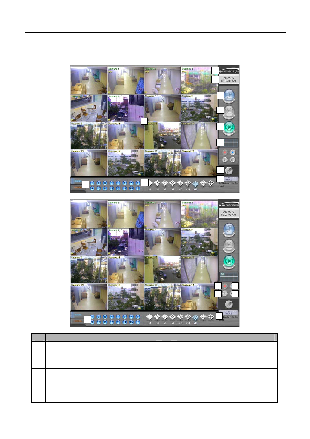
4.2 Start Program
2
4.2.1. Login
To use any of the menu, login as a user login. Press the [Tools] button on the main screen and menu will appear. On the
menu, press [Login] button to login as a user.
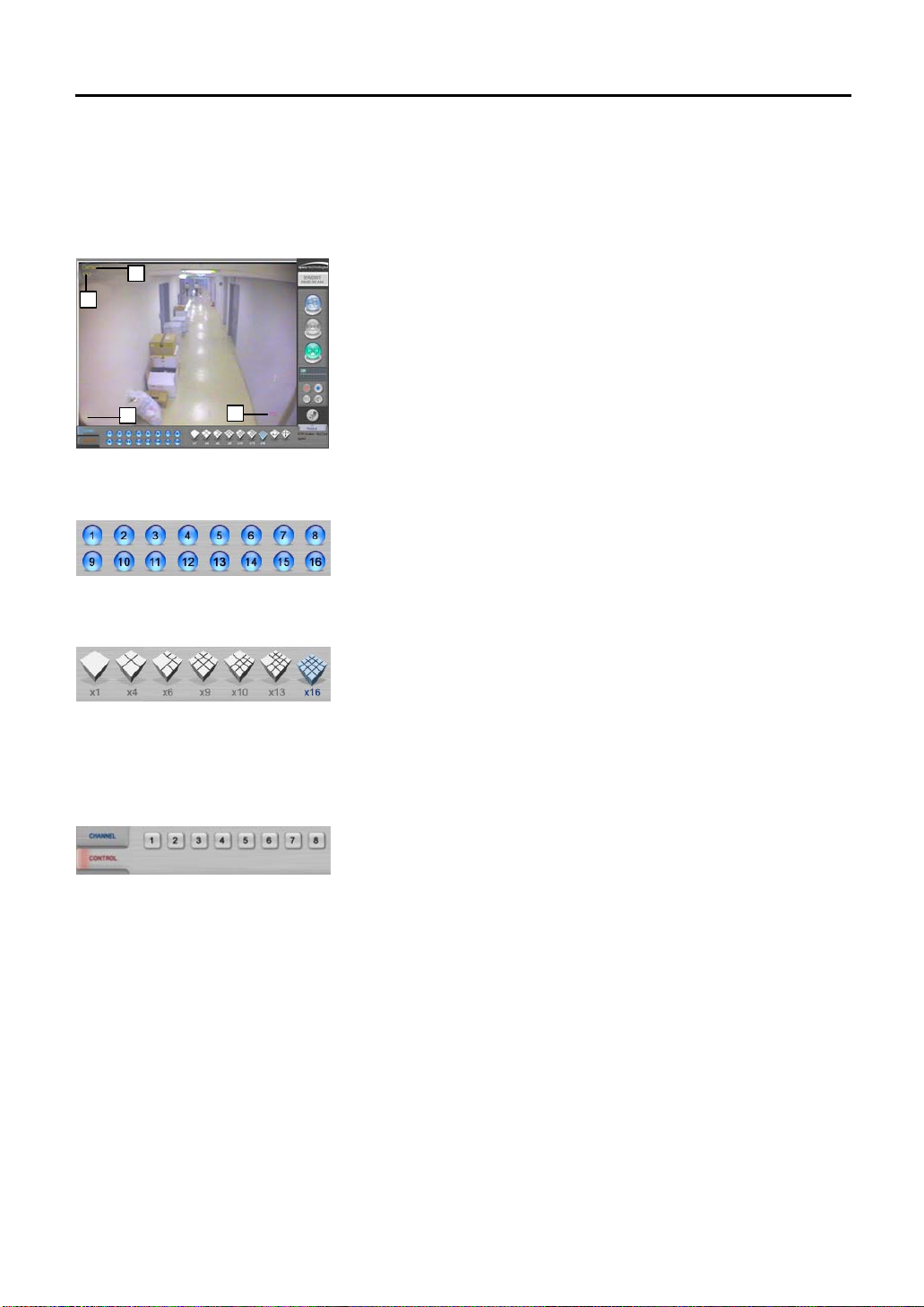
4.2.2. To see Channel Image
Each number will be corresponding with the connected camera. Press each number to see if the channel image can be
seen properly. When the channel number is pressed, only the image of the camera can be seen.
4.2.3. Split Screen Mode
According to the user environment, the current display screen can be seen in several screens or by only one screen.
When the user presses each button, the screen will change to 1, 4, 6, 9,10,13,16 split screens. Press the [Display
Division
sequence from the Settings. When [Full Screen Mode
Double click on the full screen and it will change back to main screen with the menu.
] button and the screen will automatically alternate from group split mode. Refer to the time setting for screen
] is pressed, the image screen will be shown without the menu.
3
1
Page 13
13
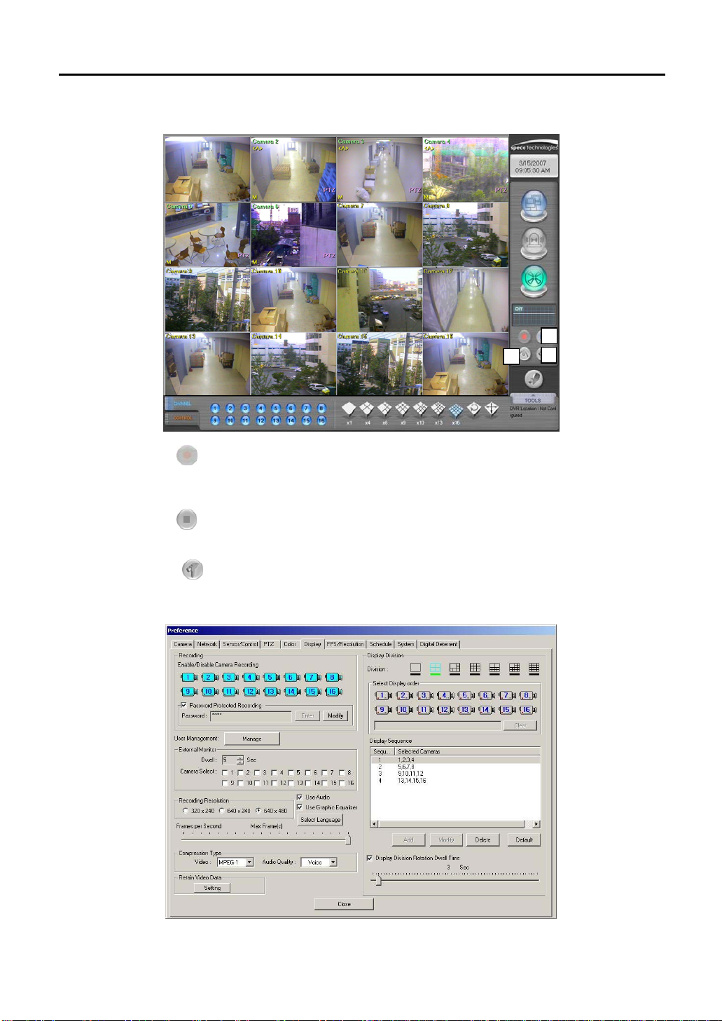
4.3 To Start Recording
2
3
1
4.3.1. Start Recording [
When the power is connected to the system, recording will start automatically after 3secs. But if recording does not start,
press the [Start Recording] button.
4.3.2. Stop Recording [
Click [Stop Recording] button if recording is not required.
4.3.3. Recording Setup [
1) Basically, all the cameras connected will be recorded. Set the image-recording environment according to user environment.
Set the recording camera from [Preference]→[Display].
]
]
]
Page 14
14
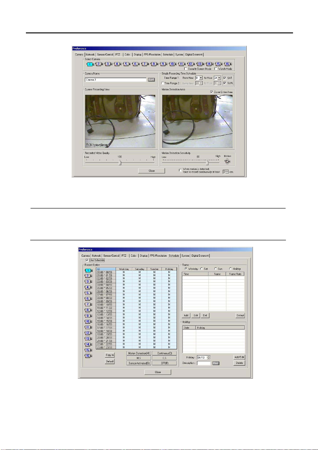
2) Set the simple recording time schedule from the [Camera] tap. If the time schedule is not set, the recording will be
24hours.
3) Set the motion detection area and tick off [Cover Entire Area] to record the camera images only when there is
motion on the selected area. When [Cover Entire Area] is selected, the whole image is active
Note 1. Click left mouse button: Creating one area box.
2. Click left mouse button and drag : Creating area box followed by drag movement.
3. Double click left mouse button : Creating all selected box area.
4. Click right mouse button : Deselect one selected box.
5. Double click right mouse button : Deselect all selected area.
4) To set the recording mode per hour of each day and channel, go to [Preference]→[Schedule]. Recording has to be
stopped in the main menu by pressing the [Stop Recording] button to set the recording schedule. Select camera
number, time and recording mode. Each recording mode will be displayed on the left bottom of each channel
screen on the main screen. For more detail explanation of [Schedule], refer to [Preference→Schedule].
Page 15
15
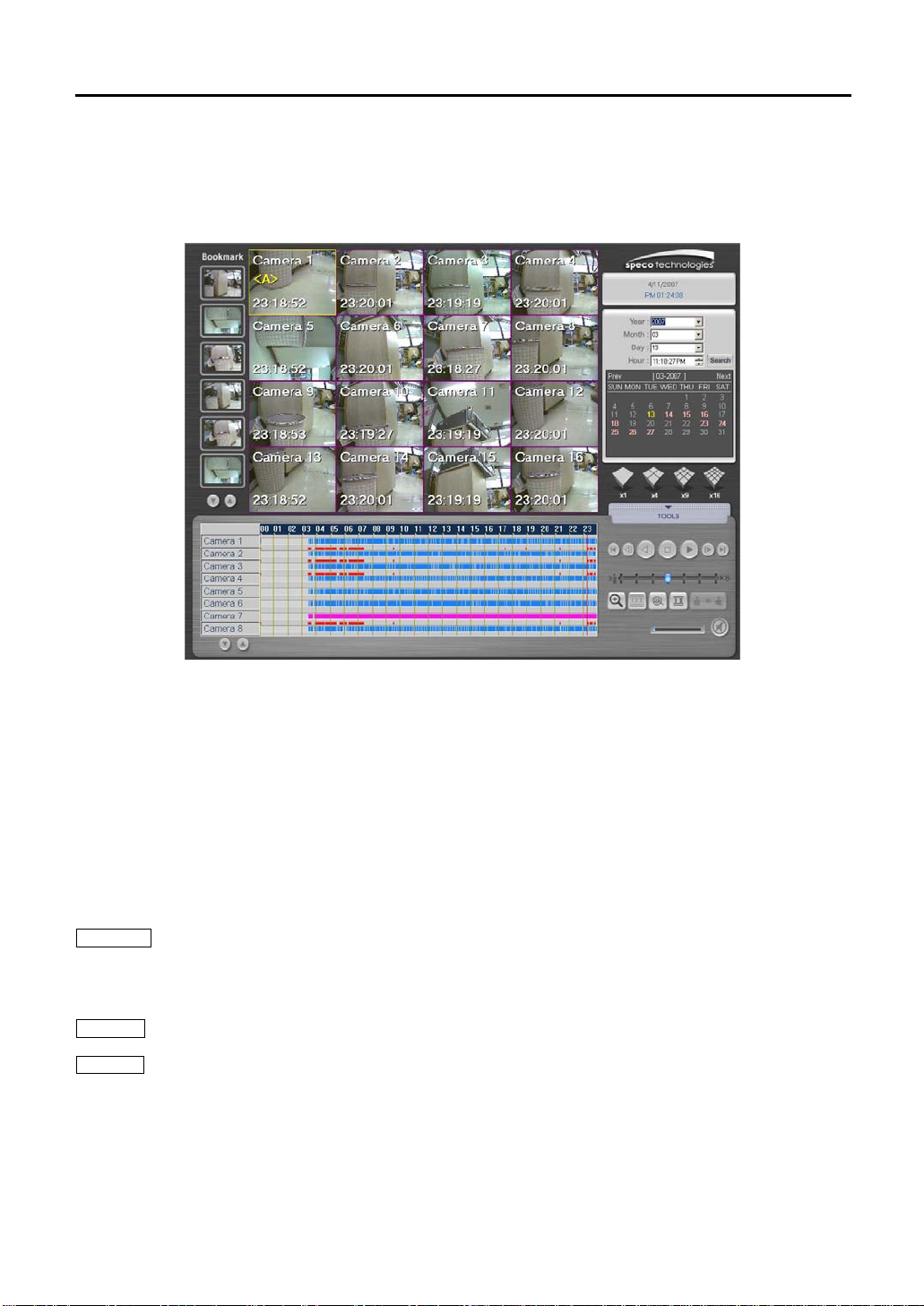
4.4 Search Recorded Image
Press the [Viewer] button on the main screen, enter a password and a confirm password and then a screen layout as
shown below will appear.
Recorded images can be played back easily by date, time and camera.
4.4.1. Search recorded image by Date
1) Select the year/ month/ day/ time from upper right category of the screen layout.
2) Date can be selected from the calendar without selecting each category. The date with recording will be indicated by
a pink color. The present date is in yellow color.
3) When the date is selected, the recorded images of the chosen date will be shown on the screen. If there is no
recording in that date, images from the nearest date will be shown.
4) To see the searched image, press (▶) button. Move speed increase bar to adjust the playback speed.
4.4.2. Search recorded image by Time
1) Image of the searched date can be searched on an hourly basis.
2) The time with recorded images will be indicated in pink color.
Following is the explanations for the graph color shown on the time graph.
Black Color : There is password on the recorded image file. Enter setting password on the DVR. After entering the
password, press the [OK] button to call up the recorded image. Refer to [Preference]→[Display] →
[Password Protected Recording] category for password setting. Be careful not to forget the password or
else the image cannot be playback.
Blue Color : Recorded image files with motion detection settings.
Pink Color : Recorded image files with continuous recording settings.
Page 16
16
5. Screen Layout
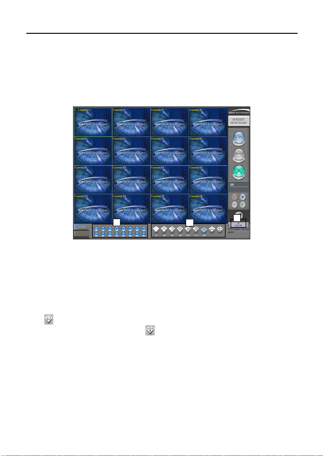
5.1 Main Screen
5
6
7
8
1
9
10
15
11
13
16
12
14
2
3
4
No. Name No. Name
1 Current Recording Screen 10 Audio Input Indicator
2 Camera Channel 11 Start Recording
3 Split Screen Mode 12 Stop Recording
4 Control (Alarm Output) 13 Search Recorded Image (Viewer)
5 System Information 14 Settings
6 Date / Time 15 PTZ Settings
7 Remote Connection / Transmission Indicator 16 Tools
8 Sensor Event Indicator 17 DVR Location
9 Recording Status Indicator
17
Page 17
17
5.1.1. Current Recording Screen
Show the images of the connected cameras. Each channel number of the connected camera and channel name set by
the user will be indicated. According to the screen status (security screen mode, watch mode), the image will appear and
a mark (M / C / M, S / C, S / S / F/ P, S) will be on the right bottom of each channel image. Refer to “Preference” for
channel name and recording settings. To enter each channel name, press the [Setup] button from the main screen and
go to [Camera]→[Camera Name] to enter the necessary content. Refer to the explanation for [Preference]→[Camera] tap.
1
2
Following is the OSD indicted on the screen.
1) Camera location: Camera 1
2) Audio connection: <A>
3) Recording Mode: M / C / M, S / C, S / S / F / P, S
4) PTZ Driver Connection: PTZ
3
5.1.2. Camera Channel
5.1.3. Split Screen Button
5.1.4. Control (Alarm Output)
4
Switch fast and conveniently between several channels to view images from
each camera. When you click Number 2 button, images from camera 2 can
be seen.
Split the current recording screen to display 1, 4, 9, 10, 13, 16 screen mode.
Cameras displayed on 4 or more split-screen modes can be instantly
enlarged for detailed inspection when left button of the mouse is clicked on
the desired camera. Double click the left button of the mouse while in
enlarged screen mode and previous split-screen modes will be displayed
The alarm output connected to the DVR can be forcefully activated. Press
the button and the sensor connected to the number will be activated. When
a sensor is detected, the number with sensor activation will be indicated.
Refer to [Preference]→[Sensor/Control] section for reference.
Page 18
18
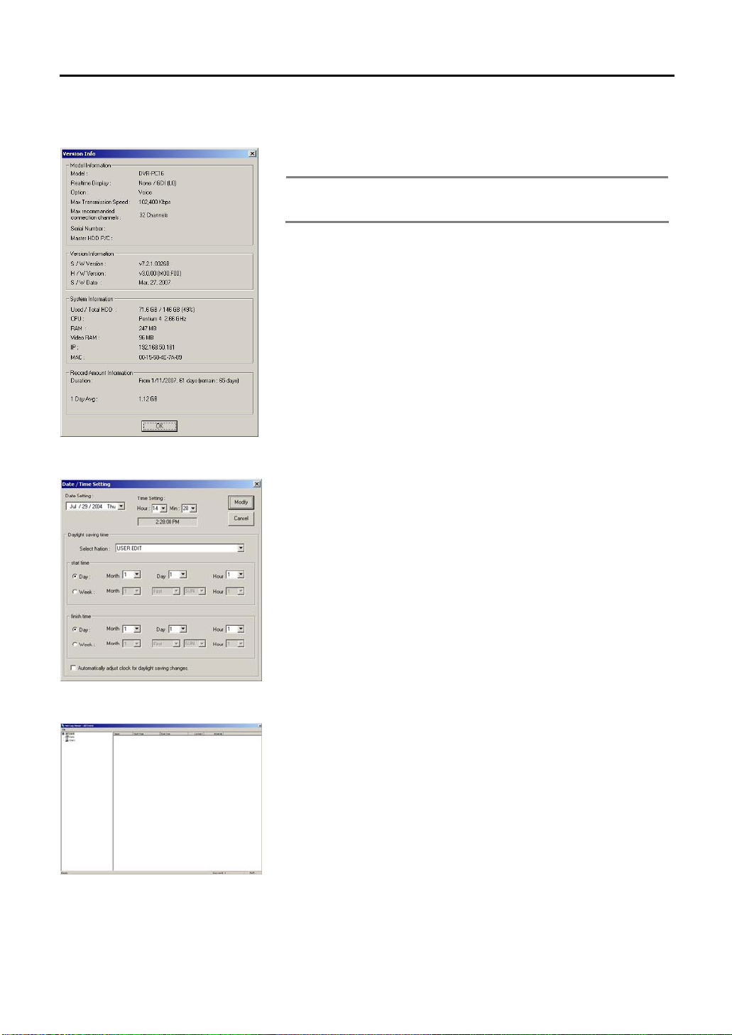
5.1.5. System Info
Click the logo on the main screen to view the general information of the system.
Double click the Speco Technologies logo “e” on the main screen to view the
general information of the DVR.
Note The contents may differ depending on the product purchased.
The S/W, H/W versions may differ depending on the product
model and the user settings.
The S/N (Serial Number) of the version information is used when the
administrator’s password is lost. Check the Serial Number when the product is
purchased. Inquire more information from the buyer or dealer if the S/N is not
in the General Info.
5.1.6. Date / Time
5.1.7. Remote Connection / Transmission Status
To change the date and time, click on the figures that show date or time on
the DVR main screen and then enter proper password.
Date / Time Setting window will appear when the password is correctly
entered. Choose “USER EDIT” in “Select Nation” category, and leave,
“Automatically adjust clock for daylight saving changes” unselected.
Make the changes on the date and time then press [Modify] button. DVR
stops recording automatically when date/time setting has been changed. Click
[Start Recording] button to start recording the images.
Transmission status indicator flashes while connecting with remote
surveillance Agent Series to indicate that it is presently transmitting.
Shows information of the connected user when the corresponding button is
clicked while the Agent Series is connected.
When the system is not connected, double click the indicator to view full
connection history, the Net Log Viewer.
Page 19
19
5.1.8. Sensor Event Indicator
The indicator flashes when the alarm sensor is operating.
Note Double click the sensor indicator with the left mouse button to
start the Log Viewer. The log viewer shows the list of occurred
events by date and type of the event.
This information can be printed or sent in files that can be
displayed in Microsoft excel.
5.1.9. Recording Status Indicator
The tape icon flashes to show the recording status and when it does not flash, it has been deactivated to show that it is not
recording.
Note When all channels are in “Watch Mode,” they are not recording.
5.1.10. Audio Input Indicator
When the audio is being recorded, its status will be shown in graphical display.
5.1.11. Start Recording
Recording of all the cameras installed will be done according to the user settings.
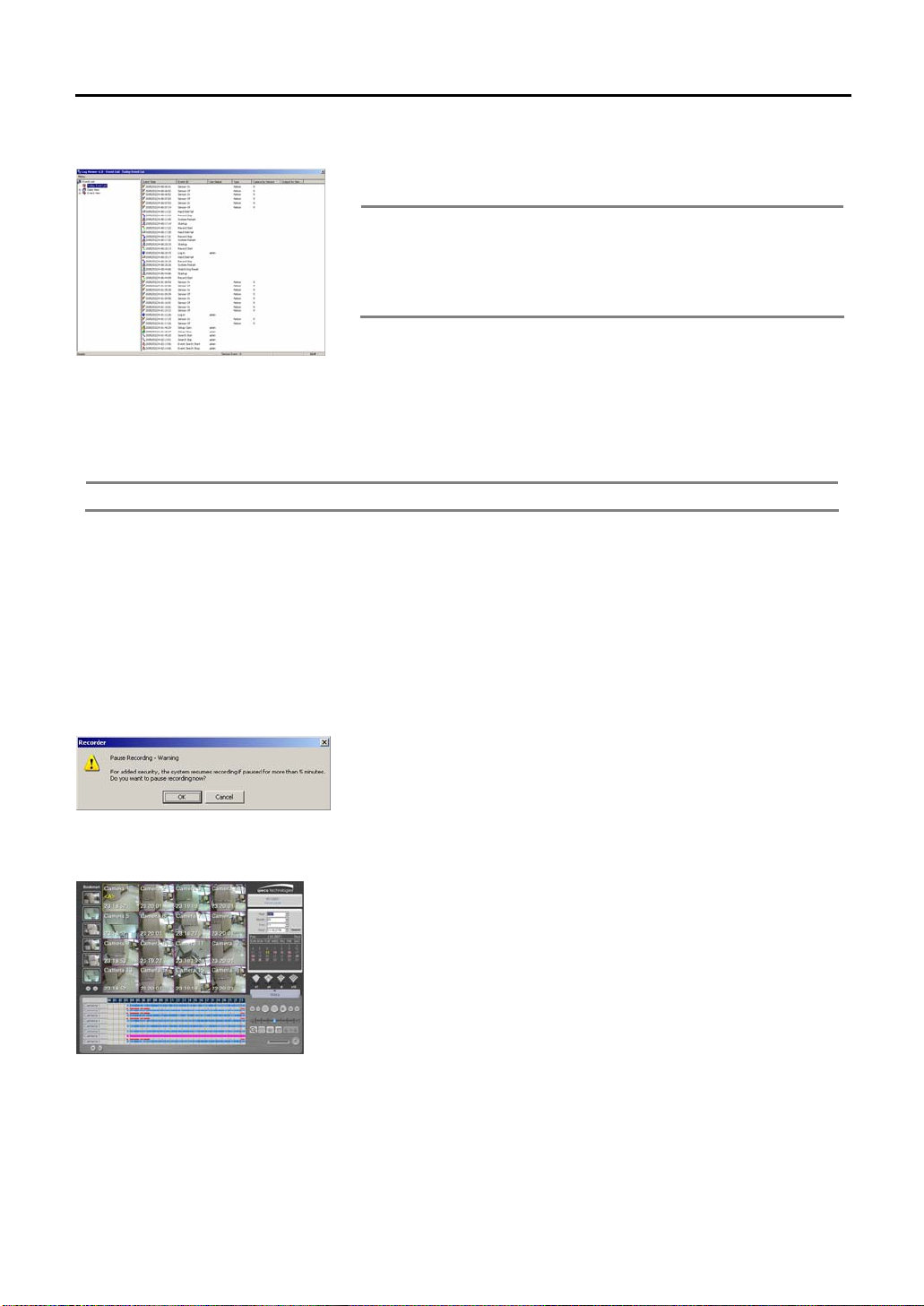
5.1.12. Stop Recording
5.1.13. Search Recorded Image (Viewer)
Stop recording of all the cameras. Click [Stop recording] button and a warning
message will appear. When the recording does not start for more than 5
minutes, the recording will start again automatically.
Start the Viewer to search recorded images.
(Refer to Using Viewer section for detail instructions)
Page 20
20
5.1.14. Preference (Settings)
Selection screen will appear for setting recording section, image quality,
desired recording time, motion sensitivity and etc. Refer to “Setting
Customized Functions” section for detail explanations.
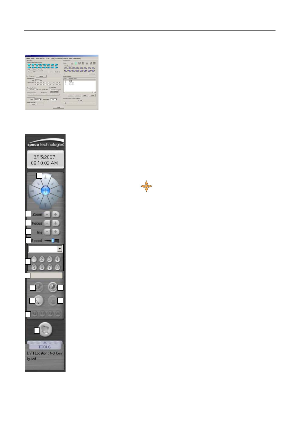
5.1.15. PTZ Setting
1
2
3
4
5
6
7
8
10
9
11
12
13
When the camera controller setting is incorrect or if it’s not installed, it will not
activate. The controller enables users to control the Pan/Tilt, Zoom In/Out,
screen adjustment functions of the camera.
Refer to “Settings”
This function can be only used on the channel screen with [PTZ] indicated on
the main screen. When PTZ panel appears on the right side of the main
screen, the “
Press the left of the mouse and it will change to arrows. Move the mouse to
move the PTZ in the desired direction. PTZ Speed becomes faster while
mouse moves far away from the center of the screen and becomes slower if
the mouse comes near by center of the screen. You may control the Zoom
In/Out using scroll button of the mouse.
The following are the explanations for each button of the camera controller.
1) Pan/Tilt
Camera with installed P/T controller will move in each direction while the
button is pressed down (The Pan controls the right left direction of the camera
and Tilt moves the camera pointer). The movement stops when the pointer is
not pressed.
2) Zoom (In/Out)
The size of the image will be enlarged(+) or reduced(-) while the button is
pressed down.
3) Focus (Near/Far)
Objects on the screen will be focused(near and far) while the buttons are
pressed down
4) Iris (Open/Close)
IRIS Open(+)/IRIS Close(-)
5) Speed
Adjust the speed of the P/T/Z
6) Preset
Displays the Preset recall buttons. (Refer to ‘Camera Control’ for the method
of saving the preset settings.
→“PTZ” tap for settings of each function.
virtual joystick” appears on the selected channel screen.
Page 21
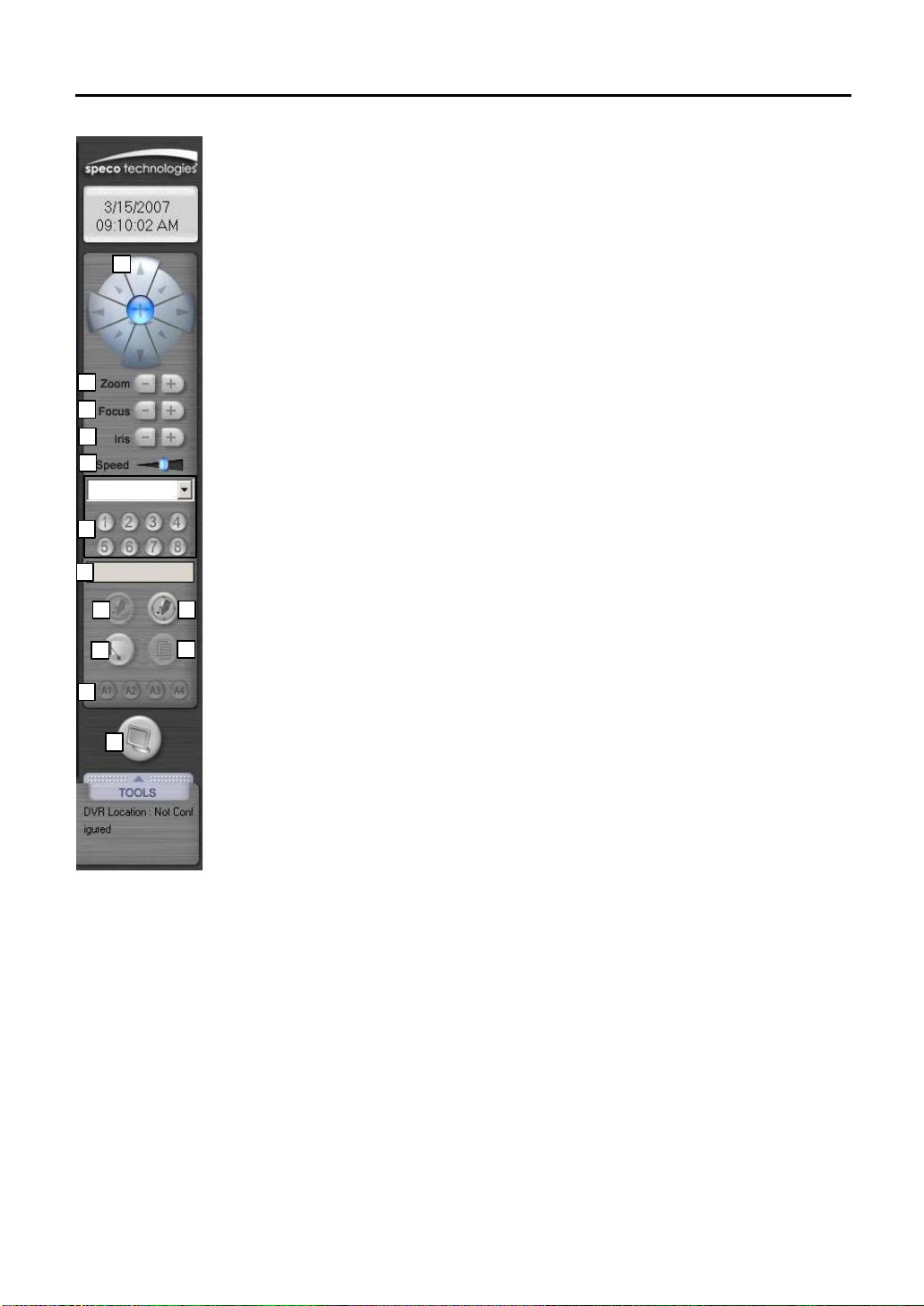
21
1
2
3
4
5
6
7
8
9
7) Preset Name
Preset Location Name of the preset number set will be indicated.
8) Auto
Move the camera image automatically. This function is limited according to the
installed PTZ driver.
9) Tour
Move according to the route of the preset location set.
This function is limited according to the PTZ driver set.
10) Wiper
Activate the wiper installed on the camera.
This function is limited according to the PTZ driver set.
11) Menu
It is a function supported on the PTZ driver and this is used when there is
other setting function.
This function is limited according to the PTZ driver set.
12) Aux1-4
The user uses this to set other extra functions that can be installed within the
PTZ driver’s limit. This function is limited according to the PTZ driver set.
13) Close
Return to the main screen after closing the PTZ panel of the main screen.
12
10
11
13
Page 22
22
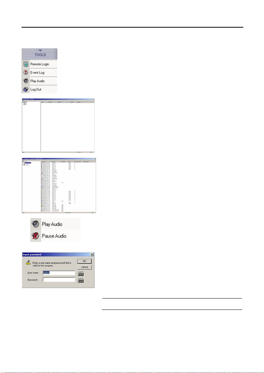
5.1.16. Tools
Press the Tools button and a menu to adjust the picture quality of the screen,
remote connection and sensor activating log file and also Log In/Log out will
appear.
Remote login
The remote transmission indicator flashes while it is connected to the Agent
Series, remote surveillance program.
It is the same screen that appears when [Network] button of the main screen
is pressed.
Event Log
Sensor Indicator flashes when sensor is activated on the connected system.
It is the same screen that appears when [Sensor Indicator] of the main screen
is pressed.
Play Audio
On/Off function for Live Audio out put.
Log In / Log Out
To use the program, login user. Press the [Log In] button to login by user.
When [Log In] button is pressed, a window will appear for the user to input
password. The system will not have any password when it is started for the
first time. Press [OK] button and login. The user can set the user name and the
password after doing this.
To prevent other users from using the program, the login user should log out
and log in again when the menu buttons are required to be used again.
→user password
Set the password for Login. Refer to “Setup
Note
setting”.
Page 23
23
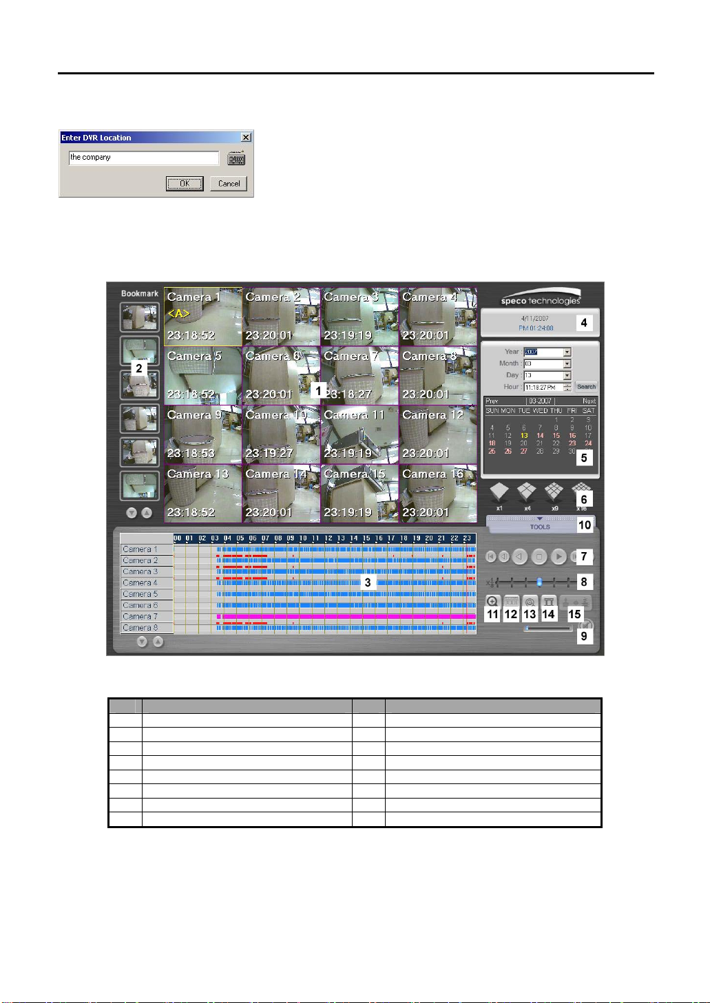
5.1.17. DVR Location
Enter the installed DVR location. Will be indicated on the main screen after it
is entered. Press the keyboard button to enter the letters.
5.2 Viewer
NO. Name NO. Name
1 Current Searched Screen 9 Adjust Audio for Playback
2 Bookmark 10 Tools
3 Time Position Indication Bar 11 Screen Zoom In/Out
4 Indicating Date / Time 12 Panorama
5 Search Calendar 13 Search Sensor Event
6 Select Split Screen 14 Adjust Picture Quality
7 Playback 15 Deinterlace Button
8 Adjust Playback Speed
Page 24
24
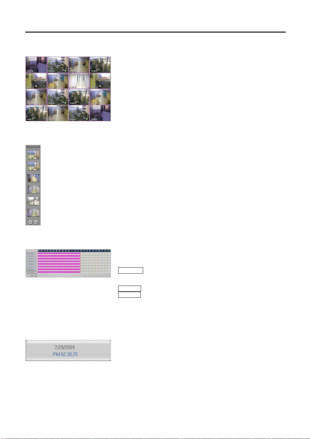
5.2.1. Searched Screen
Displays the images that match the search criteria. Up to maximum of 16
channels can be displayed simultaneously. Change the screen to 1-channel
and click [Replay] button to see real-time images while quick search you have
seen on TV.
OSD indicated on the screen is as below.
1. Camera Name: Camera 1-16
2. Audio Connection: <A>
3. Recording Time: 00:00:00 (Hr: Min: Sec)
5.2.2. Bookmark
Function to save the images temporarily while the user searches the images.
Drag the desired image for backup and bring it to the empty column to save
the image temporarily. To save more images, press the arrow button below to
move to other screens
To see the saved image, drag the mouse or double click the searched image
to see it in 1 screen mode.
5.2.3. Time Position Indication Bar
5.2.4. Indicating Date / Time
The recorded images will be shown as time graph. The user can search the
time of the image easily from the searched date. Use the mouse to move the
vertical red bar from the graph. The time is indicated for 24hours.
Black Color : The recorded image file has password. Enter the password
set on the DVR. Enter the password and press [OK] button to recall the
recorded images.
Blue Color : Recorded image file with motion detection.
Pink Color : Recorded image file with continuous recording settings.
Click the bar on 0~24 hr from the upper part of the graph and the time can be
searched in more detail.
Indicates the present date and time. The date and time shown here is set from
the DVR. Incase the date and time is incorrect, set the time from the DVR
system’s main screen. Time setting changes cannot be set from the viewer.
Page 25

25
5.2.5. Search Calendar
Select the date to search the recorded images.
Press arrow button from each category to select the date.
Select Yr/Month/Day/Time and press [Search] button.
Also, click the below calendar to search the date.
The date with recorded images will be indicated in pink color and the present
date will be indicated in yellow color.
The date without recorded images cannot be selected.
Press [Prev] and [Next] and the calendar will move to previous and next
month.
The recorded images will appear on the searched screen.
5.2.6. Select Split Screen
5.2.7. Playback
2 3 4 5 6 7
1
5.2.8. Adjust Playback Speed
Split the current recording screen to display 1,4,9,16 cameras simultaneously.
When the number of the split screen mode is more than the actual number of
cameras connected to the system, the vacant screen displays the Speco logo.
See an image in detail (1-screen mode)
A particular 4-split screen mode can be instantly enlarged to 1-screen mode
for detail inspection by clicking the left side of the mouse twice.
Click image number 3 with the left of the mouse and it will change to single
screen. Click the left of the mouse twice and the image will return back to split
screen mode.
Press the button and the searched recorded images can be seen with the
audio.
The following is the function for each button.
1. Move to the exact recorded starting point of the corresponding recorded
time range.
2. Playback backwards by one frame
3. Playback backwards
4. Pause
5. Playback
6. Playback forwards by one frame.
7. Move to 59mins 59secs of the corresponding recording range.
Adjust the slide bar to control the playback speed of the recorded image.
(Supported speed: 1/8~8X) When there is audio recorded, it can be adjusted
together with the playback speed.
Page 26

26
5.2.9. Adjust Audio Playback
Adjust the audio volume for audio playback. If the volume cannot be adjusted,
check the device administrator after ending the program.
Click the Speaker button if the audio is not required and press it again to allow
for audio playback.
The recorded audio can be heard for a screen, 1X mode. That is to hear the
recorded audio, select a screen from 1~4 channels and playback the audio by
1X.
When audio is being recorded, the surveillance screen and searched screen
will indicate “<A>” on the upper part of the screen to show that Audio had been
activated. For DVR-PC8/16 Series, the audio recorded can be corresponding
with camera channel no. 1.
Recoded audio playback is being executed at selected 1X mode of 1~9 split
modes. It means that you should select channel from 1~9 screen with “<A>”
and play it in 1X mode.
5.2.10. Tools
Press the [Tools] button and the menu will appear.
Refer to “Search Tools” part for detail explanations of each menu.
Smart Search
The hour range of recorded images can be searched by seconds,
according to the particular motion area selected by the user. It can be
searched easily by each date, hour.
(Advances Post Processing)
APP
Use Image Post Processing for a still image, among the recorded images
to get higher picture quality. Thus, it can be saved or print out as JPG or
BMP state with higher picture quality using several filters.
Media Backup
Recorded images can be back-up by CD or DVD.
Still Image / Minutes Backup
Recorded image can be saved by file (bmp /jpg /dsf /mpeg format).
Print
Print out the searched image by connected printer.
Configure
Window will appear to add the printer and to select searched option,
USB Eject
Functions enable to safely remove when USB is connected.
Exit Search
End the searched screen and go back to the main screen.
Page 27

27
5.2.11. Zoom In/Out
After clicking the button, select the screen for zoom in/out. Click the left button
of the mouse and the screen will enlarge. The screen will diminish when the
right side is clicked. The users can Zoom In/Out using wheel mouse if
installed.
5.2.12. Panorama
5.2.13. Sensor Event
This function enables the user to see the selected image by splitting the
images by second. First, click [Panorama Function] and select the screen to
replay in detail. Next, click [Replay] button and the screen will show as
recording screen split by per second.
Select recording image when sensor event arises. First, select recorded
image button to call up recorded image before using this function.
To search sensor event,
1. Click [Sensor Event] button and execute the Sensor Event category.
2. Date of sensor event category and camera images where the sensor
event occurred, will appear in the screen.
3. Select the desired sensor event list and click [Search] button or left button
of the mouse twice to see the images where the sensor events have
arises.
4. Select the date of sensor event list by clicking [Previous Date] or [Next
Date.
Page 28

28
5.2.14. Adjust Picture Quality
Click Image Adjust button to adjust the searched screen. Select each
functions and it can be seen directly in the searched screen.
1. Grayscale: Make the screen black and white.
2. Equalize Contrast: Equalize the brightness and darkness.
3. Lowpass Filter: Delete high frequency of signal.
4. Highpass Filter: Delete low frequency of image signal.
5. Edge Enhanced Filter: Make the edge clearer.
6. Noise Reduction Filter: Eliminate noise.
7. Brightness: Adjust brightness of the screen.
8. Contrast: Adjust contrast of the screen.
Click [Initialize] button and the image effect set by the user will be cancelled
and return to default.
5.2.15. Deinterlace
Removes feathering, which appears in motion detected area recorded in 640
480 in playback. Display method, Odd Field/Even Field/Full Frame, converts in
order when this button is pressed. Default is Full Frame (640
feathering is caused at this state. However, by selecting Odd/Even, resolution
changes to 640
feathering.
×240, where vertical resolution is reduced in half, removes
×480), and
×
Page 29

29
5.3 Search Tools
5.3.1. SmartSearch
How to Use SmartSearch
1. Select the channel desired to search in the Viewer to 1-channel mode.
2. Press the SmartSearch button.
3. The system will require a password if the file you searched for contains a password.
4. Set the time you require. The image for time that you search for will appear if you press the [Go to Start Position]
button.
5. Click either [Search Next Movement] or [Search All] after selection.
6. Time for images after search result information appear in the result list.
7. You can see the first picture on the playback screen when you select the time zone.
8. Use the buttons in the “Search Result” to view the results.
9. Click [Close] button to finish the SmartSearch.
SmartSearch consists of below layouts.
No. Functions No. Functions
1 Search / Play-back Window 5 Search Option
2 Currently Searched Date and Time 6 Search Condition Settings
3 Channel Information 7 Search Result Play-back
4 Search Area Section 8 Search Result / Search Result List
Page 30

30
5.3.1.1. Play-back Window
The green color represents selected area. You can design searching areas
with below buttons to catch up the areas where motion was detected.
This playback window is to play recorded images. You can select either
“Search All” or “Search Next Movement” to playback record motion pictures.
When playback by selecting from search result list, shows the selected
categories.
5.3.1.2. Currently Searched Date and Time
Show the camera channel information for the recorded images.
5.3.1.3. Channel Information
Show the camera channel information for the recorded images.
5.3.1.4. Search Area Section
Square
You can freely select searching area in square shape.
Block
You can design the searching area on pixel basis. (16X16 pixel)
Move
You can edit the size and position of the selected area.
Delete
You can cancel the selected area.
5.3.1.5. Search Option
View Search Process
When you select “View Search process”, you can see all the images while
searching in the playback window. It may take longer search time. Without the
selection, the windows will playback the recorded images by motion detection
only.
Zoom
You can zoom in and out the played images, or playback the recorded images
in either zoom in or zoom out mode.
Sensitiveness
You can set motion sensitiveness from 1 through 100. The larger the number
you select, the more sensitive the system will be with a small amount of
motion. Normally, put the setting to 100.
Page 31

31
5.3.1.6. Search
To start, you can select the starting time. When you select the [File Begin] list,
it will search for recorded saved file at present regardless the set up time. To
view the beginning of an image before searching, set the start time and press
[Go to start] button. Then, the image will appear.
End Time
Select the image files by part. Selecting [File end], the system will search the
entire file regardless of present time.
Go to Start
Click [Go to start] button after selecting the time you want in order to preview
images in search.
Quick Search
You can speed up the searching speed. When the searching speed is
increased, the sensitiveness goes down. This is helpful when you search
images, which have been recorded with high frame rate.
Search Next Movement
It will stop searching when it finds the right images through search condition.
Then, it will keep searching when you select [Search Next Movement].
Do not use this function without checking the “View Search Process” option.
Search All
You can select the beginning through the last part of the file, which has been
recorded.
Stop Search
You can stop while searching.
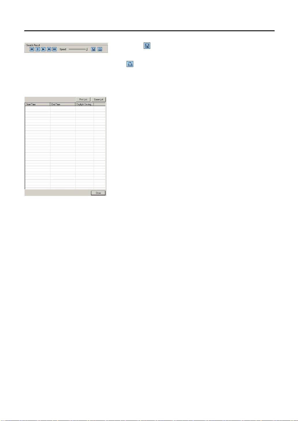
5.3.1.7. Search Result Play-back
You can playback the required image among the searched result list.
Go to Start Position [
The file will move to the beginning screen of the images, which is being
playback.
Pause [
The image being playback will pause.
Playback [
The selected file will playback. You can control the playback’s speed.
Fast Forward Search [
The selected file can be fast playback.
Go to Last Position [
The file being playback will move to the last screen.
Playback Speed [
Control the playback speed by moving the slide bar.
]
]
]
]
]
]
Page 32
32
]
]
5.3.1.8. Search List
Save Screen [
Save the image on the playback screen as BMP or JPG file.
Print [
Print the image of the playback screen by the printer.
Search List
Shows search result lists.
Erase List
Erase all the search results.
Search Result List
When there is a movement from the set up domain, you can add it to the list.
From the list, press the [Playback] button so that the screen window will
playback.
Close
Close the SmartSearch.
Page 33
33
5.3.2. APP
The Basic Method to Use the APP
1. Select the channel desired to process in APP in the Viewer to 1-channel mode.
2. [APP] button is activated when moving to previous hour range by pressing [Search Previous Hour] button in the
Viewer.
3. Click the [APP] button.
4. It will ask for file password when the required file has a password.
5. Use the scroll bar to move to the time of images, which needs revising and select the revised images from the
“Preview” window.
6. Set the value of the applicable filter by clicking [Option] Button.
7. Among the [Processing Modules] category, click the applicable filter button and the revised image will appear in
[Post-processes] window.
8. When the revised image is not of satisfaction, click the [Reset] button first before applying other filter.
9. When the images had finished revising, save or print by JPG or BMP file. The image used in the “Post-processed”
window will be saved or printed.
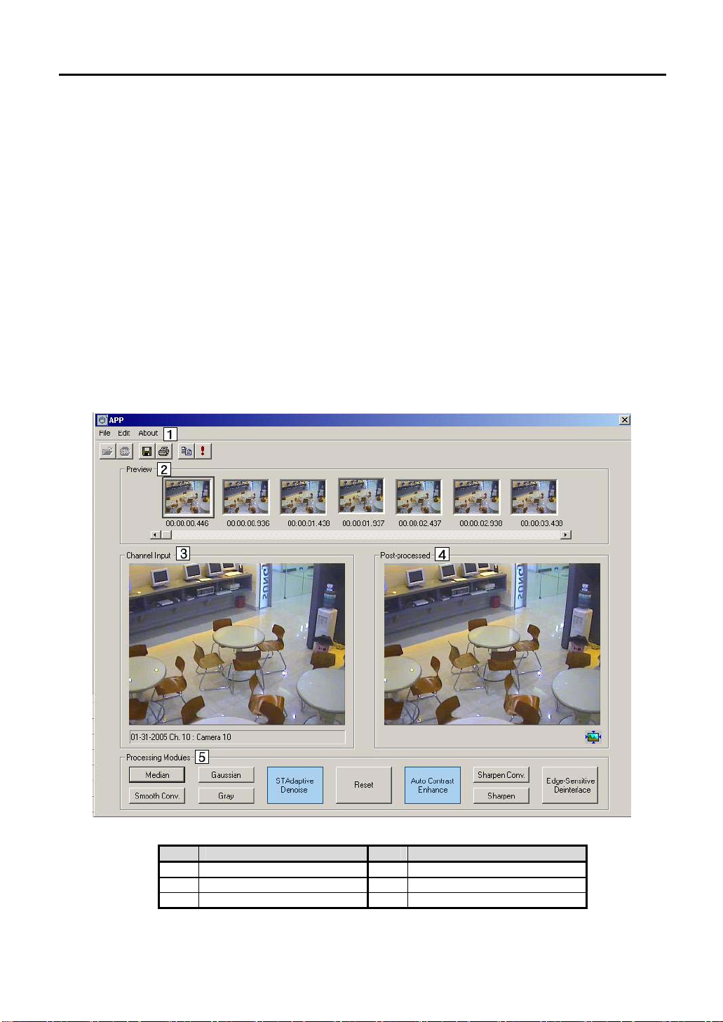
APP Screen Layout
The screen layout of APP is as shown below.
No. Functions No. Functions
1 Menu 4 Post-processed
2 Preview 5 Processing Modules
3 Channel-Input
Page 34
34
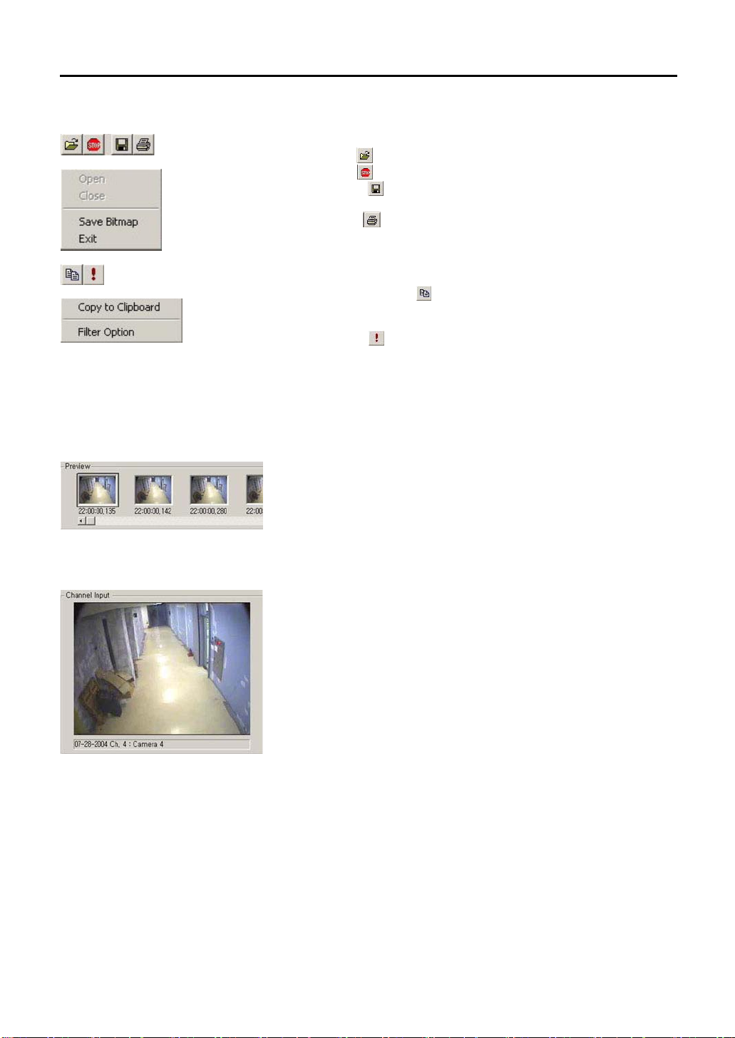
5.3.2.1. Menu
5.3.2.2. Preview
5.3.2.3. Channel Input
File
1. Open File (
2. Close File (
3. Save Image (
window as JPG or BMP file.
4. Print Image (
window.
5. Close: End APP program.
Edit
1. Copy in the Clipboard (
“Post-processed” window to clipboard. In other Picture editing program,
use “paste.”
2. Filter Option (
“Processing Modules” category)
Information
The information for APP program can be seen.
The 7 images can be previewed. Search the location with the scroll bar and
the pictures will be updated automatically. Click the revisable image among
the 7 images. Then, it will appear in [Channel Input] window and
[Post-processed] window by 320 x 240. The numbers shown under each
image of the Preview window is the image information.
It is the original image of the chosen image, which is shown in the Preview
window.
File Information
Show the file information such as date, channel, and title for the file that is
open.
): Used to open up the file. (Deactivated)
): Close the file that is open. (Deactivated)
): Save the images appeared in the “Post-processed”
): Print out the image appeared in the “Post-processed”
): Copy the image shown in the
): Set the option value of various filter. (for details, refer to
Page 35
35
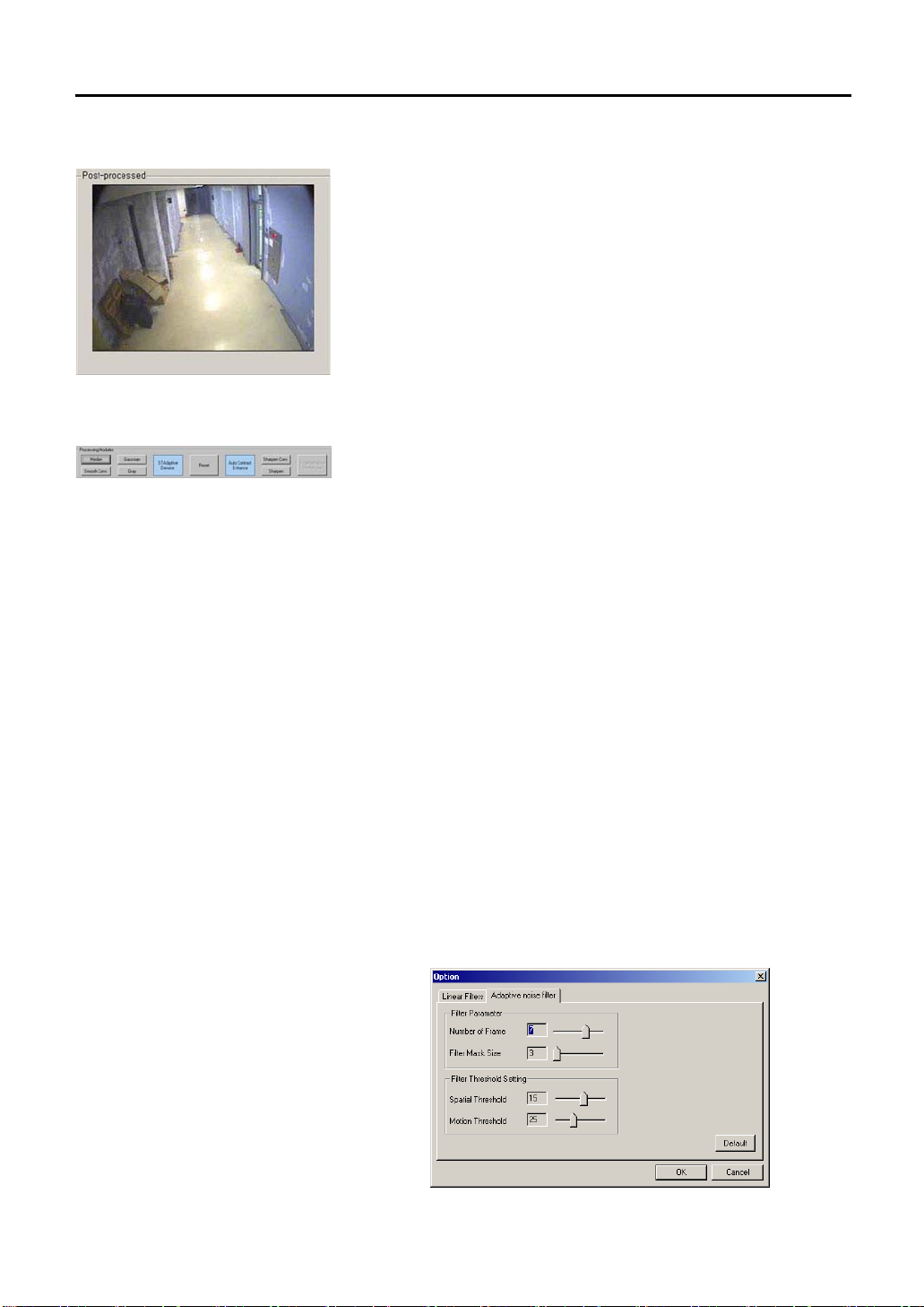
5.3.2.4. Post-processed
Shows revised image. The image gets updated whenever the filter is opened.
5.3.2.5. Processing Modules
These are filters to revise the image. They are used to revise the image to get
a neater image.
Reset
This is to reset the revised image to the original image. The effect of the
applied filter will be gone when the Reset button is pressed.
STAdaptive Denoise
It is a filter to improve the chosen image by using the forward and backward
images. Its advantage is, it decreases the bluntness that appears in the dark
images.
The filter is applied by the following four categories.
1. Number of frame: The picture quality becomes stable and cleaner by
increasing it. But the best effect is shown when the value is lower for
brighter environment and higher for darker environment.
2. Filter Mask size: The picture quality becomes stable and cleaner by
increasing it. But in whole, the image can be less clear.
3. Spatial Threshold: The picture quality becomes stable and cleaner by
increasing it. But the detail part of the image will not be easy to
differentiate.
4. Motion Threshold: The picture quality becomes stable and cleaner by
increasing it. Input low value for the times in bright environment and high
value for the times in dark or without movement as an after image can
develop for the movements appearing.
Below is the example picture after applying [STAdaptive Denoise].
Page 36

36
Note Various filters can be applied together.
Example,
Auto Contrast Enhance
Increase the color and light intensity of the screen automatically to increase
the screen’s resolution.
Sharpen Convolution
Increase the resolution by effective to use on images with non-clear objects.
The disadvantage is that the picture decreases when it is used excessively.
As the setting value increase, the object differentiation will be easier but the
picture quality will not be good.
Sharpen
Improve the resolution of the image by emphasizing the object’s boundary
line. It has a disadvantage of lowering the picture quality as Sharpen
Convolution function does. As the setting value increase, the object
differentiation will be easier but the quality will not be better.
Edge-Sensitive Deinterlace
It is a function to enlarge the recorded image of 640x240 mode to 640x480
mode. This enlarging method is different from the existing mode. The
boundary line is preserved while enlarging so the picture quality is maintained
while the size is enlarged. If the image is recorded 640X480, contour of the
image can be deviated. This phenomenon appears frequently when the fast
motion is recorded. By using this filter in 640x480, deviated contour of the
image is fixed.
Median
It is efficient to remove specks/spots or noise in the image. Use the setting
value appropriately as the image looks as if it had been drawn with water
paint when the setting value is higher.
Smooth Convolution
It is efficient to eliminate noise. It gives more natural feeling Median. But the
disadvantage is that, the image will be hazy when the value is too high.
Gaussian
It eliminates the noise in whole. It is similar to Smoothing Convolution but
relatively more natural than Smoothing Convolution. The noise eliminating
effect is bigger as the setting value increase.
Gray
Change the image to black color.
Real Image View
When viewing the recorded data which recorded by 640x480, there comes
icon at the bottom of right side. You can see the original size of
recorded data by clicking this icon.
① [STAdaptive Denoise]→② [Auto Contrast Enhance]→③ [Sharpen], better picture quality can be get
from the revised image.
※ [Edge-Sensitive Deinterlace] filter and [STAdaptive Denoise] filter can not be applied together.
Furthermore apply these two filters first before applying other filters when there is a need to apply other
filters together with these two filters. When these two filters are applied later, they will be applied to the original
image and the filters applied previously will be canceled.
Page 37
37
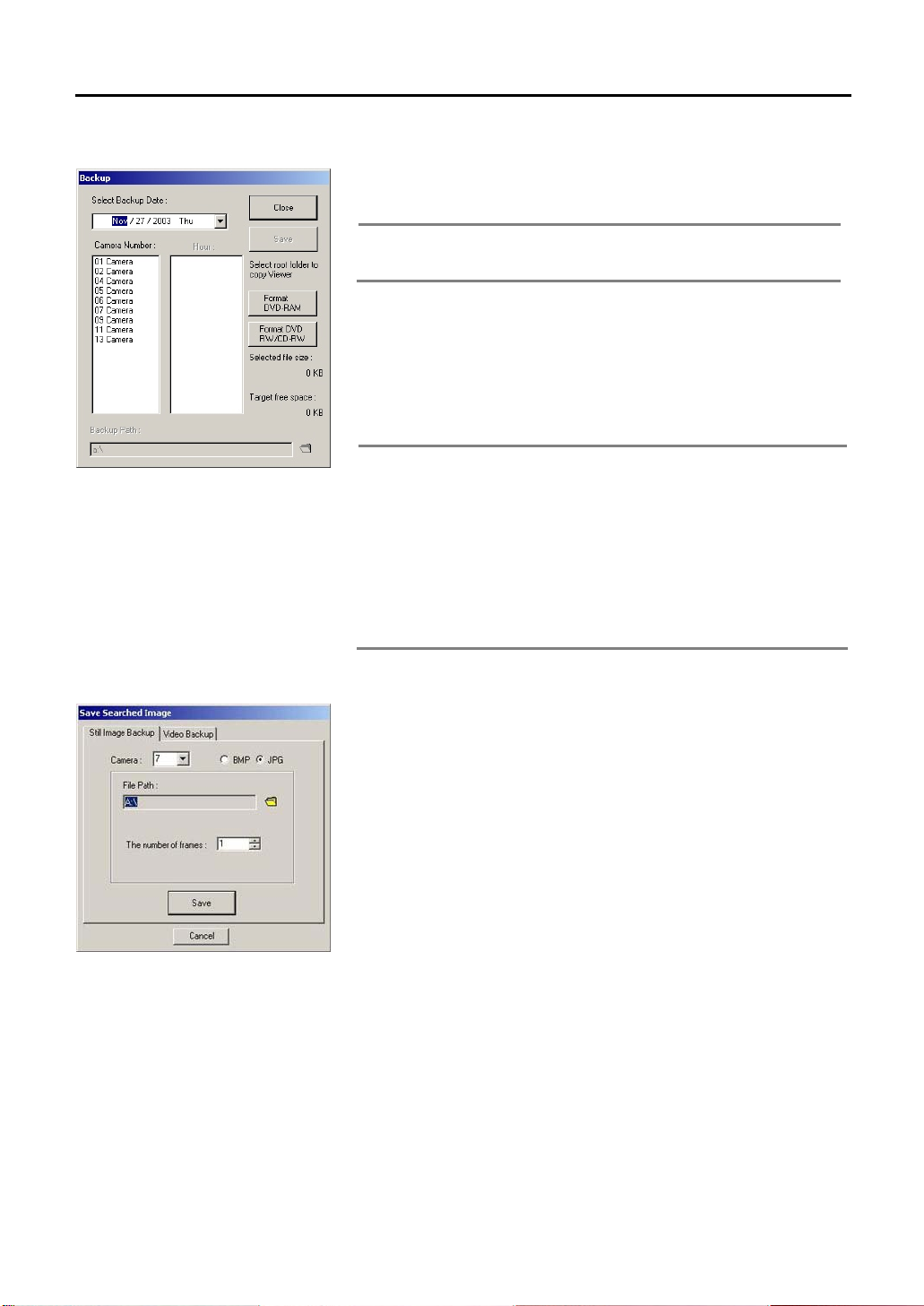
5.3.3. Backup
Select the time and save the image in the backup device. These files can be
called up in the normal PC (window based).
Note Backup device supported by the viewer are CD-RW and
DVD-RW, and USB for the interface. To add additional backup
device, inquire from the buyer or dealer.
To backup the recorded file,
1. Click the ‘CD backup’ button in the main screen of the viewer. A box will
appear to set desired date, camera number, time and backup path.
2. Select the desired date, camera, and time in order.
3. Set the backup path by clicking the [Folder] button.
4. Save the recorded file by clicking [Save].
Select several cameras or time ranges at the same time and the
Note
color of the background will change and they will be selected.
Press once more on the time ranges and the selection will be
disabled.
The saved images recorded by “Backup” can be recalled on
normal PC (Window series), with the corresponding media
installed.
If it is backup to a CD by DSF file, the Viewer to see the DSF file
will be exported also. Run the backup viewer in a PC and the
5.3.4. Save Searched Image
Still Image Backup
Save and store images continuously from the current search screen in JPEG/
BMP format on Dumbdrive , CD-R or DVD. The BMP format has better picture
quality but has bigger capacity than JPG. The user can choose one of the two
formats to save.
To save the searched screen in images,
1. Search recording image.
2. Click [Pause] button to replay the saved screen.
3. Click [Still Image Backup].
4. Image box will appear to set Still Image Backup path.
5. Select camera number of the screen to save.
6. Select the saving method (BMP/JPG).
7. To indicate the save path, click the [Folder] button.
8. Click [Save] button to save the image.
saved file can be viewed.
Page 38
38
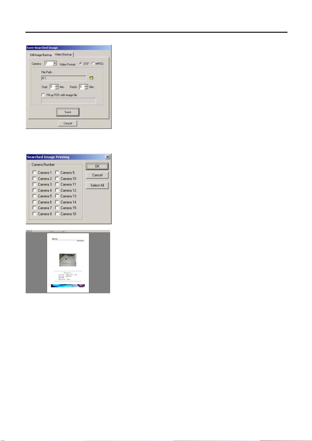
5.3.5. Printing
Video Backup
To save image by Partial Image Backup,
1. Search recording image to save.
2. Click [Pause] button after searching recorded image.
3. Select Partial Image Backup tap.
4. Select the camera number of the screen to save.
5. Choose a saving method (DSF, MPEG).
6. Select the path to save the file. You can save data by selecting FDD,
removable disk, external disk drive or flash memory.
7. Select the time to save.
8. To save in the FDD, select “Fill up FDD with image file”. When the image
is more than the disk capacity, save them on several disk.
When the setting is finished, click [Save] button.
To print the searched screen,
1. Check whether the printer is connected and the power is on.
2. Select the camera number of the image to print.
3. Check the print image in the print preview.
4. Click [Print] button. Or click [Close] button when printing is not required.
5. Press [Select All] button to print out the image of the entire channel. The
entire connected channel will be selected at once.
Page 39

39
5.3.6. Configure
Add Printer
Click [Add Printer] button to install new printer.
1. Click [Add Printer] button to use the [Add Printer Wizard] to add the new
printer.
2. Select printer location. Select local printer when the printer is directly
connected to the DVR.
3. Select the manufacturer and model from the menu. If your printer came
with an installation disk, click [Have Disk].
4. Follow the instructions on the screen. After the printer is installed, print
out a test page to confirm the proper set up of the printer.
5. After completing the installation to add printer, go to DVR setting and
click the [System Backup] on the upgrade tap for Backup.
Search Option
Select “CD Search” to search backup images on the CD. Only used when the
Viewer is started from other computer after CD backup from the DVR.
Page 40
40
6. Setting Customized Functions
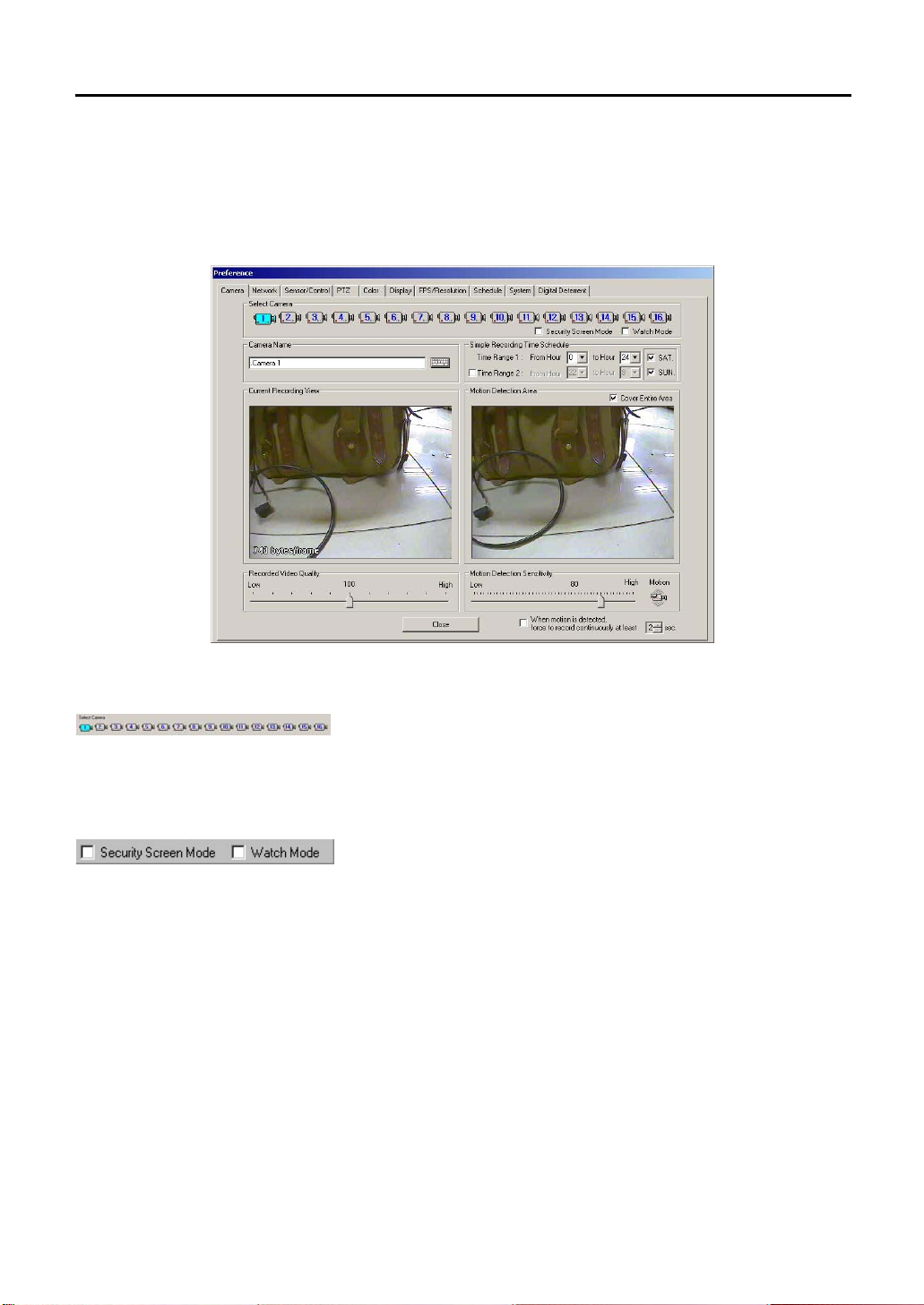
Press the [Setup] button on the system’s main screen and various functions for the system can be set on the Preference
Window comprised with 9 tabs.
6.1 Camera Setting
6.1.1. Selecting Camera
Select a camera for desired time, motion detection range, image quality,
resolution, motion sensitivity, etc.
6.1.2. Select Security Screen/Watch Mode
Security Screen Mode
When the Security Screen Mode is checked, the selected camera displays
Speco Technologies logo on the screen, and the channel title displays
“Security Mode” to show that Security Screen Mode is operating.
Watch Mode
When the Watch Mode is checked, the system will not record any images.
Page 41

41
6.1.3. Camera Location
Enter installing location of the selected camera. Click on the keyboard icon to
display virtual keyboard screen. Click the virtual keyboard screen with the
mouse to input camera location.
6.1.4. Simple Recording Time Schedule
6.1.5. Current Recording View
Input dot (.) in front of the title. Then, the channel number of the title will not be
seen in the main screen.
For example, input “.B/D Side” is input; the screen will appear as “B/D Side” in
the screen. When only “B/D Side” is input, the screen will appear as “1. B/D
Side”.
Time Range 1
Select the recording time of images from the selected camera.
For example, select from 0 to 24 hour and the recording will resume
continuously for 24 hours. When 0 to 12 hour is selected, the images record
for the first 12 hours and stop recording for the next 12 hours.
Whenever the installed sensor detects any motion, recording resumes will
even during the off-recording time.
(Refer to “Recording Schedule” for more detailed information)
Time Range 2
To select another recording time other than the recording time selected in
Recording Time 1, checkmark the box in front of Recording Time 2 to select
the time.
For example, when the Recording Time 1 is selected from 9 to 18 hour and
when the second recording time frame from of 20 to 24 hours is desired,
checkmark on the Recording Time 2 and chooses between 20 to 24 hours
time frame.
Weekend Recording Function
Select Saturday and/or Sunday to record.
When recording is not required on either Saturday and/or Sunday, turn off
appropriate checkmark.
For example, to record on Saturday and not on Sunday, set up as following
picture.
Recordings of images from connected CCTV cameras are displayed on the
current recording view.
The [**bytes/frame] shown on the left bottom of the picture is the file size of a
frame (1 screen page). With this file size, the user can roughly calculate no.
Of hours that can be recorded into the hard disk.
Page 42

42
6.1.6. Motion Detection Area
Motion detection area can be selected on the motion detection area screen
after the checkmark on the “All Ranges” selection is turned off.
1. Click the left mouse once: One field box is created.
2. Click left mouse and drag: Field box is created following the direction of
the drag.
3. Click the left mouse twice: The whole area in the chosen box is created.
4. Click the right mouse once: Disable one of the selected boxes.
5. Click the right mouse twice: Disable the entire selected box.
When the selection is made, any movements in the selected range will be
recorded.
Note Recording is not supported if you don’t configure the motion
detection area after disable “All Ranges” setting.
Cover Entries Area
When all ranges are selected, any motion detected in the entire screen is
6.1.7. Recorded Video Quality
6.1.8. Motion Detection Sensitivity
6.1.9. Motion Recording
recorded. The all ranges are set as default.
Use the slide bar to control the setting value for clearer recording image.
(Recommended recording picture quality: 100)
Motion sensitivity of the images can be adjusted by using the slide selection
bar. We recommend users to record smaller movements with higher
sensitivity level. (Default: 80)
Continuous recording [
DVR is always in continuous recording.
When the camera shape button (
recorded whether there is change in the image or not. Thus, if it is on, the
Motion Detection Sensitivity will not be used.
When motion is detected, Recording will be proceeded in the period of given
time set up
]
) is pressed, the images will be
Page 43

43
6.2 Network
In this section, the selections for the Internet, user ID and other options are selected to transmit images using Agent
Series remote distance surveillance system.
6.2.1. Enable Network
Network Setting
Click the [Edit] button and the Internet settings screen will appear. Input
required information as requested.
Dynamic IP
IP Address might be changed under ‘automatic IP’ environment.
This function helps to connect DVR by unchangeable MAC Address using
additionally installed Dynamic IP Server which is independent from IP change.
Fixed IP Address is required In case of Dynamic IP Server.
DVR automatically allocate IP and sends this IP and MAC Address
periodically to the Dynamic IP Server. Agent connects to DVR through
dynamic IP Server using MAC Address.
Select ‘Use DyIP’ box and click ‘Edit’ Button to call up ‘DyIP server IP
(211.202.3.176)’ setting window.
Network Adapter
Select the present network card attached.
IP Address
Input the IP address used in network setting. Select “Obtain an IP address
automatically” and it will be automatically allocated in the OS. When the OP
address is automatically allocated in the OS, the DVR cannot be connected to
the RemoteAgent.
Select “Specify an IP address” and an IP address will be selected
automatically. Click the keyboard, which is beside the box to input the OP
address. Then, input the address in the virtual keyboard that appears.
Gateway
Input gateway address when it is needed.
Page 44

44
DNS
Input DNS setting when it is needed.
Press [OK] button after completing all the settings to apply.
6.2.2. Remote Connection Time Limit
Connection Time Limit
Select “Connection Time Limit” to limit the connection time with Agent Series.
The time limit can be set up to maximum of 120 minutes. For example, to
connect and transmit images through Agent Series for only 30 minutes, select
“Connection Time Limit” and set 30 minutes. When 30 minutes have been
passed, the Agent automatically disables connection.
Auto Disconnect on no activity after
To stop the transmission within the pre-selected time limit when there is no
response due to transmission errors, select “Auto Disconnect on no activity
after” and select the desired time limit. The maximum time limit can be set up
to 20 minutes.
6.2.3. Additional Network Options
6.2.4. Setup of Port Range
Bandwidth Limit
Select this category to limit network transmission speed. The user can
temporarily select bandwidth. Number displays current bandwidth setting.
Remote Overlay Control
Control the live images in RemoteAgent remote controller. Detailed
information settings cannot be used in DVR while controlling the live images
in the RemoteAgent.
Allow Time Synchronization
The RemoteAgent remote controller sets the time of the DVR to be same with
it. The DVR can use the remote notification category to set the time in the
RemoteAgent. So, the RemoteAgent must be registered in the remote
notification category to have the same time with the DVR. The RemoteAgent
transmits the time of the RemoteAgent to the DVR in intervals.
Time Synchronization
Synchronize DVR time with RemoteAgent. If there is RemoteAgent which
designed to be Time Server in same network, it synchronizes time of DVR
once in a day(AM 03:00).
TCP and UDP number can be changed between “1028-60000”. The basic set
up uses Default. It is necessary to reboot after changes
Page 45

45
6.2.5. Remote Event Notification
Allow notification of events to RemoteAgent. DVR can notify to RemoteAgent
even though it is not connected.
6.2.6. Transmission Time Limit
Note Following events are notified to the RemoteAgent.
Add
IP input box will appear when [Add] button is pressed.
When the keyboard appears in the screen, enter additional IP address.
Click the [OK] button and it is added to remote notification category.
DVR only notifies the Event to the RemoteAgent, which is in the Remote
Notification category. Add RemoteAgent IP to Remote Notification category to
observe the DVR with RemoteAgent. Maximum of 10 can be added in the
category.
Delete
Select the desired user name on the list and click [Delete] button to delete the
user name.
To limit the image transmission time after sensor activates.
If the image is not transmitted within the set time, the transmission will be
stopped automatically.
1. During sensor event (notifies event or connects channel)
2. Stop/start recording
3. Abnormal camera input
4. Turn off or Shutdown(Power Off)
5. Rebooting by any other reasons
To get notification, the RemoteAgent must be under
operation.
Page 46

46
6.3 Sensor/Control
In the preference tap, set connecting camera to the Sensor and set the sensor for External Output with various other
output.
6.3.1. Enable Sensors and Controls
6.3.2. Sensor Time
Select this function to use the sensors and controls.
Select desired sensor operating time. The default time is set as 0 to 24 hour.
To use this category, turn off “Recording Schedule
→Use Schedule”.
Page 47

47
6.3.3. Select Sensor
6.3.4. Sensor Type
6.3.5. Sensor Recording Time
6.3.6. Use No.4 sensor for Auto Shutdown
Select sensor for setting.
Cameras Associated with Selected Sensor
Select the camera to be associated to the installed sensor. Multiple cameras
can be connected to a single sensor. Activate sensor by clicking the desired
sensor with the mouse. Then, select the camera number for the connecting
sensor.
PTZ Preset
To set the Preset location of the camera, assign the number at the bottom of
the camera.
External Output connected to each Sensor
When sensors detect any motion and are connected to a pre-selected alarm,
the alarm can be automatically triggered. When there is intrusion, the sensor
will be detected and the alarm output port will automatically halt. Select sensor
and camera. Then, select the alarm output port to use. The connected alarm
output port in the P series will be shown as activating and the chosen alarm
output port will change to red color.
.
Select the type of sensors to be preset on alarm from the N/C (Normal Close)
or N/O (Normal Open). Only one type can be selected.
Sets the preset duration for recording time when a sensor is triggered.
Maximum recording time is 5 minutes. When the preset recording time is up,
the recording of images detected by sensors halt and the system returns to
the previous recording mode until the sensor is triggered.
In case the power supply fails, the Auto-Shutdown functions and the system
shut down safely. The user can set up when the use the Auto-Shutdown (UPS
battery backup time) during the discontinuous of power supply. Inquire from
the place of purchase for the UPS used.
For example, when the UPS battery is set for 1 minute, the system shut down
safely after power supply excess 1 minute.
Page 48

48
6.3.7. Recording Mode
When you want to record only the images on sensor-detected camera in full
frame speed instead of the current recording images at the standard frame
rate while the sensor is activated, choose “Optimize Frames Per Second”.
When you want to record both current images and all images on
sensor-detected camera, choose “Normal”.
Note Optimize Frames Per Second:
Records with the maximum speed of product system, without
regard to the present record setting
Note “Motion Sensor” may not be supported depending on the
product.
6.3.8. Sensor Etc
Display mode freezes after sensor
When a sensor corresponding to a selected camera detects any motion, the
system automatically display the images from the camera for the duration of
the preset “Display Mode Freeze after sensor,” regardless of the display mode
selected. When the recording time is up, users can manually select either to
keep sensor display mode or return to the original display mode. Click on the
current recording screen when you want to return to original display mode.
Sound Use
Users can manually select this function to use sound when Check sensor
activates.
Motion Sensor
When the motion sensor is selected, alarm will trigger when the motion is
detected.
Select the sensor and the camera of the image desire to detect when using
the “Motion Sensor”.
Users can manually select the use of relay function.
To Continuous Recording
When continuous recording is selected, it will continuously record while
motion sensor is activating.
After motion sensor stops, recording mode will be changed to previous menu.
Page 49

49
6.3.9. Video loss Detection
Video loss Detection
Select this category and the screen title will appear as “Video loss” when the
camera cable is disconnected or cut. The alarm time will follow Sensor
Recording Time.
Recording Failure Alarm
Turn on sensor output Number 7 (located second to the end) from internal
system while the recording activity is normal at the system. This function turns
off the Relay when a problem occurs or the recording stops.
Use the External Output No.2
Configure this function when there is Video loss.
Recording Failure Alarm
Reboots the system after warning alarm if the DVR fails to record.
Use the External output No.1
When System is recording it turns on Relay No.15. This function turns off the
relay if there is any problem with record.
When user manually stops the recording, the alarm doesn’t activate.
No.15 Relay can’t be used with other functions while using it as an External
output.
Note Numbers can be changed by the number of camera channels.
Page 50

50
6.4 PTZ
This setting tap is for camera control.
Note The manual may differ because the control functions vary between the manufacturers or by the products used.
The manual provides the standard model.
6.4.1. Use PTZ
6.4.2. Select Camera
6.4.3. Enable PTZ
6.4.4. PTZ Protocol
Select this category to use the camera controller for Pan (left right) / Tilt (up
down). To activate the installed PTZ, select this category and the camera
controller will be prepared automatically. This category is not selected in
default.
Select the desired camera to control. Several cameras can be selected for a
controller. Selected camera will change to blue. Click once more and the
selection will be disabling
Click on this check box to enable PTZ functions.
Click the down arrow button and PTZ protocol list will appear
Page 51
51
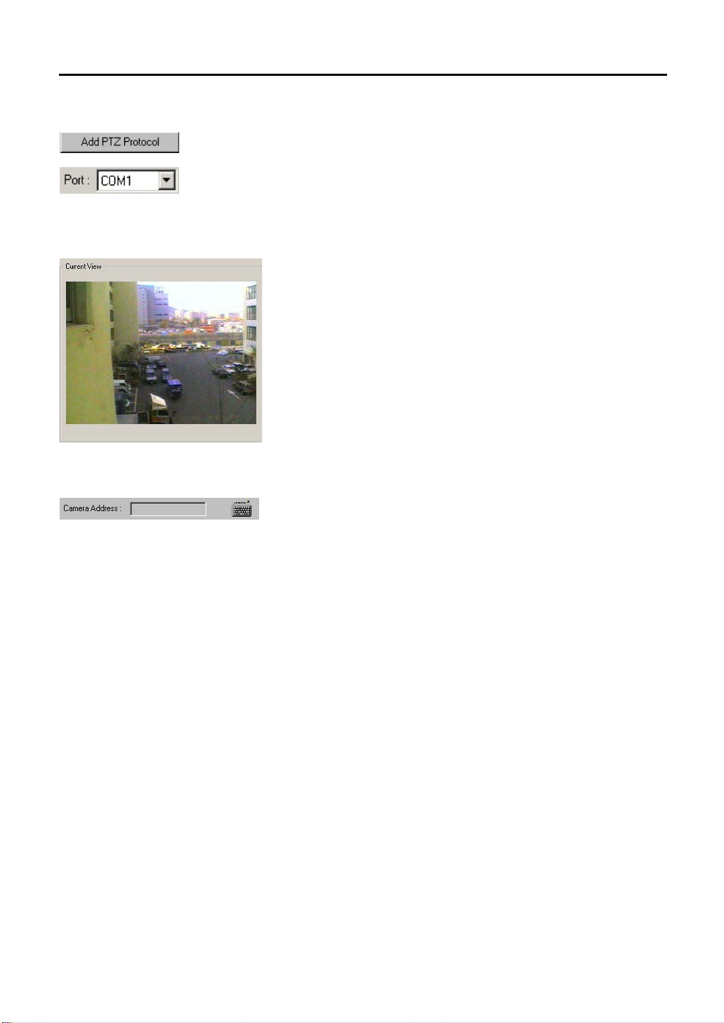
6.4.5. Add PTZ Protocol
6.4.6. Current View
To install new camera protocol, select “Add PTZ Protocol”
Port
Select the port to install PTZ protocol. Selectable port appears when arrow
button is pressed.
Show the current viewing screen of the chosen camera. See this screen to
control the location of selected camera.
6.4.7. Camera Address
Click on the keyboard to input the suitable controller number according to the
controller type. Maximum of 255 numbers can be set for controller number.
The controller number in the actual controller should correspond with the
selected camera number.
To operate camera control functions,
1. Set the type of camera protocol.
2. Select the desired camera to control.
3. Select Enable PTZ.
4. Input the Camera Address using the keyboard icon.
5. Control the camera location by using Pan/Tilt buttons.
Page 52
52
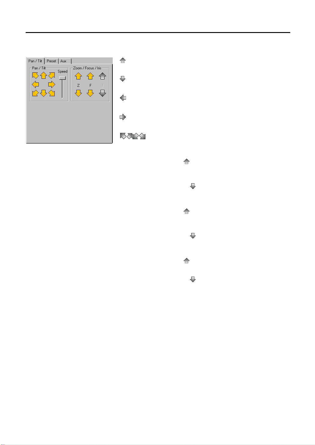
6.4.8. Pan/Tilt
: Click on the up arrow button to Tilt the camera in upward direction until
the desired angle is reached.
: Click on the down arrow button to Tilt the camera in downward direction
until the desired angle is reached.
: Click on the left button to Pan the camera left until the desired position is
reached.
: Click on the right button to Pan the camera right until the desired position
is reached.
: Click on the diagonal arrow buttons to move the camera to each
position.
Zoom In
Click on the up arrow button (
screen. When the image is enlarged to an ideal size, release the button.
Zoom Out
Click on the down arrow button (
the screen. When the image is reduced to an ideal size, release the button.
Focus Near
Click on the up arrow button (
from the preset camera position.
Focus Far
Click on the down arrow button (
point from the preset camera position.
Iris Open
Click on the up arrow button (
Iris Close
Click on the down arrow button (
) to gradually enlarge the size of image on the
) to gradually reduce the size of image on
) to focus in the image in the closest point
) to focus out on the image in the furthest
) to open the iris.
) to close the iris.
Page 53

53
6.4.9. Preset
Automatically moves the camera to a preset position. The preset position is
the combined settings of pan, tilt, zoom and focus
Set
Set current camera position in memory.
Move
Move the camera to the currently selected camera position.
Location
Enter the installed location of current camera.
To input camera position in memory,
1. Use the Pan/Tilt functions to control the camera position.
2. Select the desired number from preset position menu for mew setting.
3. Auto Preset Button by pressing [Set] button.
4. Input the present location by pressing [Location] button.
To use preset camera location,
1. Select the location to move in preset position.
2. Move to the location by pressing Preset [Move] button or by clicking the
item of the selected category with the left mouse.
Scan
Rotate the currently memorized camera location in PAN sequence.
6.4.10. Exterior Equipment
The exterior equipment icon will not appear when the function is not supported
by protocol
Camera Power
The camera power can be turned on or off by checking/un-checking Camera
Power.
Aux
When any of the accessories are installed to a camera (such as siren),
choose the number corresponding to the accessory used and enter the
desired preset operating time. Then, click on the Aux. Icon. The selected
accessory will operate for the duration of entered preset time and
automatically shut off when the preset operating time expires.
Registered Accessory Information
Register or modify information on each currently installed accessory. Click on
the accessory’s number to view registered information on the accessory.
Page 54
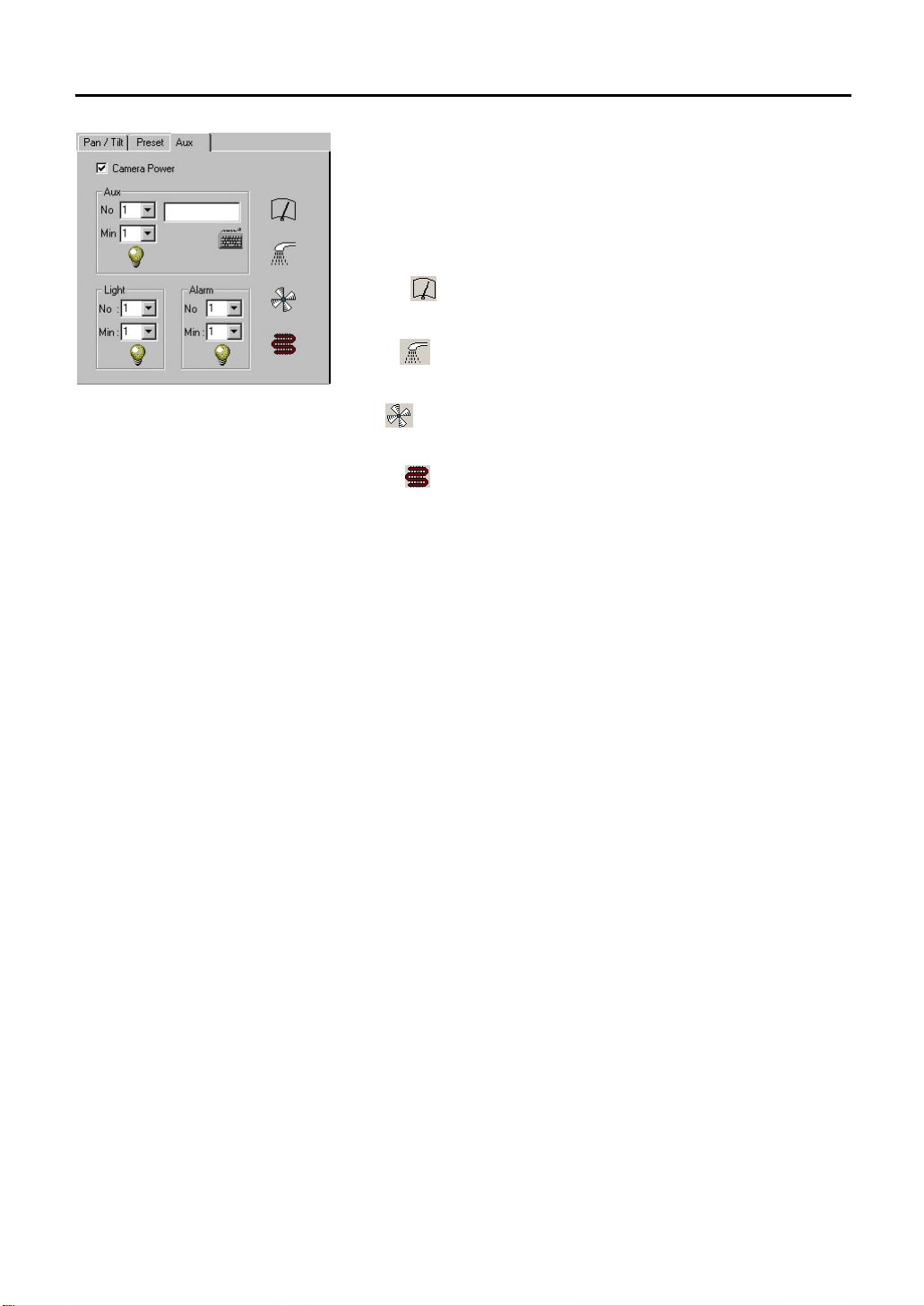
54
Light
The exterior light will be kept on for the duration of entered preset time and
automatically shut off when the preset operating time expires.
Alarm
The alarm will be kept on duration of entered preset time and automatically
shut off when the preset operating time expires.
Wiper [
To operate an installed wiper, press on the Wiper icon.
Pump [
To operate an installed pump, press on the Pump icon.
Fan [
To operate an installed fan, press on the Fan icon.
Heater [
To operate an installed heater, press on the Heater icon.
]
]
]
]
Page 55

55
6.5 Color
Video Input Signal Adjustment allow users to individually adjust camera’s color brightness, contrast, Chroma U, Chroma V,
and Hue for the adjustments.
6.5.1. Select Camera
6.5.2. Current Viewing Screen
Displays the screen of the selected camera.
6.5.3. Camera Color Setting
Selected camera icon will highlight blue.
Setting value is from –100 to +100.
Brightness
Adjust Brightness of the currently selected camera.
Contrast
Adjust Contrast of the currently selected camera.
Chroma U
Adjust Chroma U of the currently selected camera.
Chroma V
Adjust Chroma V of the currently selected camera.
Hue
Adjust the Hue of the currently selected camera.
Default
Return the currently selected camera’s color tone to default settings.
Page 56
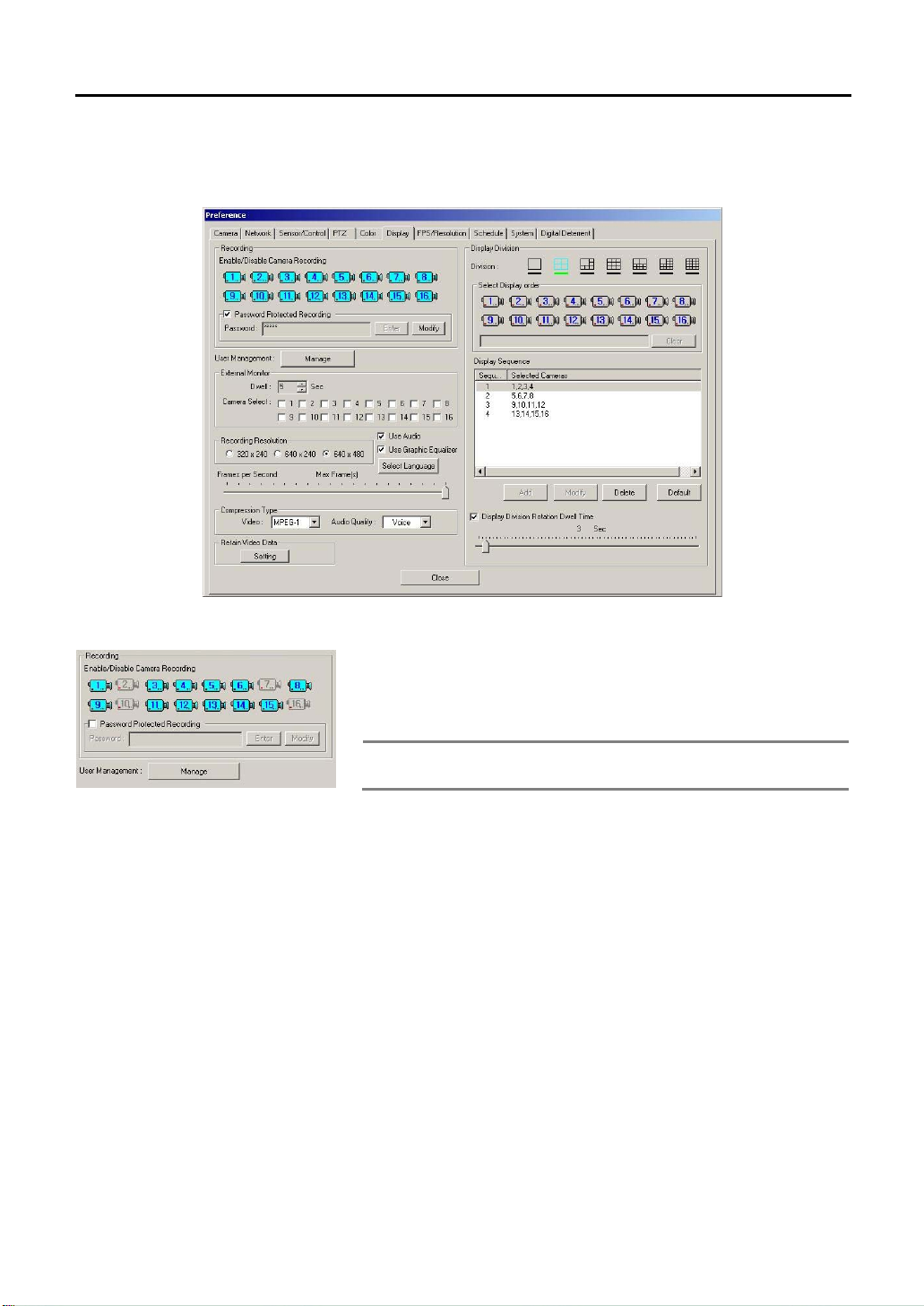
56
6.6 Display
Setting for each recording channel, sequence and password is done in this menu.
6.6.1. Recording
Enable/Disable Camera Recording
Not all the installed cameras can record. Only the selected cameras can
record images.
Note The installed cameras that are either not connected to the system
Password Protected Recording
Save password on recorded image. The user can encode password while
opening up the recorded image. The encoded password has to be inputted in
the Agent Series to view the recorded image.
or without power are shown grayed out.
Page 57
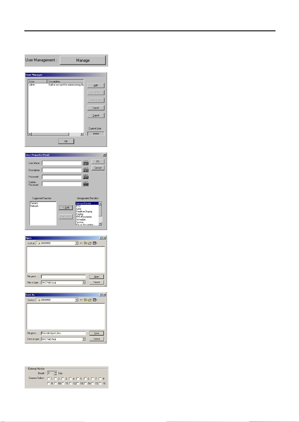
57
6.6.2. User Management
Set up the login and password when logging into the main menu. By clicking
[Manage] button, window to set up the user name and password appears.
The system users can be managed by selecting [User Management] button.
The administrator (admin) set as default can add, edit, remove other users or
give authority to functions to each user.
Add
1. User Name: Enter user name.
2. Description: Enter necessary descriptions of the user.
3. Password: Enter user password.
4. Confirm Password: Confirm the password once again for check up.
5. Supported Function: To give authority, select the function in
“Unsupported Function” presses the [Add] button to add into the
“Supported Functions”.
6. Unsupported Function: Limiting the user from using particular functions.
The user cannot use the functions, which are in the unsupported function
column.
Remove
Select a user to delete and click [Remove] button. The “Admin” cannot be
removed.
6.6.3. External Monitor
Import
Call up the user category which is made up of UserList.dul file.
Export
Call up the user category which is made up of UserList.dul file.
Use this when you want to use additional TV monitor other than PC Monitor.
On TV monitor It automatically changes the channel of vision which is
connected to camera.
Page 58

58
6.6.4. Recording Resolution
6.6.5. Audio/Graphic Equalizer/Select Language.
Shows the present recording resolution size set among “320
240”, “640×480” mode. To adjust the recording resolution, stop recording
first.
Use Audio
User can On/Off the audio recording.
Use Graphic Equalizer
×240”, “640×
6.6.6. Frames Per Second
6.6.7. Compression Type
6.6.8. Data Keeping Data
User can Enable/Disable the Main Equalizer (
Select Language
User can select the language they prefer. System will be rebooted if user
changed the language setting. It supports 12 languages.
Set the recording frame rate per second by using the slide bar.
This function becomes ‘disabled’ while selecting ‘FPS/Resolution’ settings for
each cameras.
Video Compression
User can select compression type (MPEG-1 or MPEG-4). Select MPEG-4 to
decrease data size and improve image quality, but frame rate is reduced half
of MPEG-1. For example, selecting MPEG-4 in 120fps system allows
recording in 60fps.
Audio Compression
User can select Voice, AM, FM Audio quality.
This function might not be supported depends on system features.
User can select image storage period by each channel. The box for channel
selection appears when [Setting] button is pressed. Select the storage period
by each channel. To select all channels, select [All Channel], and then set the
period. To select different time period for different channels, select storage
period by pressing arrow button next to the number. By selecting storage
period to 1 day, it will be applied the following day.
).
Page 59

59
6.6.9. Display Division
Select a screen mode from 1, 4, 9, 10, 13, 16-split mode.
Camera Sequence Selection
Select the order of display cameras. The orders are different according to a
recording screen mode selected.
To select 4-Split Screen Mode
Select 4-screen split mode, decide the sequence to show the camera group.
For example, 8 cameras are installed and in 4-screen mode, the cameras are
grouped as 1, 2, 3, 4, 5, 6, 7, 8 as the second group.
Select camera 1 and the cameras in the group will be selected. After deciding
the sequence of 2 groups, the time will change to the time set in “Alternation
Mode Time.”
Clear
Cancel the selected order of cameras to be displayed. By using the [Clear]
button, a selected order with an error can be easily deleted.
Display Sequence
When selecting the display order, click [Add] button to see the selected
display order schedule on the current recording screen.
Add
The currently selected display order is added to the “Display Order”. When
added to the schedule, the order can be modified.
Modify
To change the display order selected, select the order in the display order
schedule to modify the order.
Delete
Delete unnecessary schedule. All the schedules cannot be deleted and at
least one schedule category has to be in the list.
Default
Return to the default setting.
Page 60

60
6.6.10. Automatic Alternation Mode
Select “Display Division Rotation Dwell Time” and select alternation time by
sliding the selection bar. Automatic alternation mode displays images from
each camera in rotation according to the selected options on the current
recording screen.
For example, to set Automatic Alternation Mode when 4 cameras from 1 to 4
have been installed,
1. Select a desired split-screen mode from the recording display mode
(choose 1-screen mode).
2. Select the camera sequence of the 4 cameras. Set the cameras into 4
sets like 1
camera 1 will change in color.
3. Click [Add] button.
4. Secondly, select camera number 2.
5. Click [Add] button.
6. Thirdly, select camera number 3.
7. Click [Add] button.
8. As the method above, set the camera number 4 and add in the “Display
Sequence”.
9. Select “Display Division Rotation Dwell Time”.
10. Set the alternation time to 3 seconds by using the slide bar.
11. Click [Close] button to close the Setup box.
Now, the DVR current recording screen mode will change to a 1-screen mode.
The first set of camera “1” is displayed on the screen followed by the next set
of camera “2” in 3 seconds. The third set camera “3” is respectively displayed
in 3-seconds intervals. Lastly, the fourth set camera “4” after 3 seconds. This
shows that the 4 sets of 4 cameras are displayed on the current recording
screens at a 3 seconds interval.
→2→3→4. First, select camera 1 with the mouse. Then, the
Page 61

61
6.7 FPS/Resolution
Adjust the frame for each channel of the DVR with this menu. (On the DVR-PC8/16 Series, recording frame setting can
be adjusted but it does not support resolution setting per camera.)
6.7.1. FPS and Resolution Setting per Camera
To use this setting, the recording should be stopped.
FPS Setting per Camera
The setting cannot be higher than the total recording frame setting value of
the all the cameras.
Ex) In case the model used is of 240fps and 1~8 channels are set as 20fps
each, the total setting value for 9~16 channels cannot be over than
240-(20X8)=80fps.
6.7.2. System Recording Performance
Move the slide bar of each camera to set the frames. The maximum recording
frame rate per camera is 30fps. In case the frames do not go up after certain
value; it means the maximum frame has already been exceeded. The
maximum frames of the system differ according to the selected recording
mode. (Refer to Recording Setting)
6.7.3. Display Max
This feature allows the system to maintain to the speed for monitoring possible
to capture in DVR-PC8/16 series, which the Recording speed and monitoring
speed are same. User can view the best quality image when this feature is
selected since the recording speed is set low even though monitoring speed is
supported to max.
For example, in case of using DVR-PC8/16, monitoring speed is maintained to
max frame not depending on the recording setting frame number in regards to
max frame by each display resolutions. Even though recording speed by
channel is set as 1 frame in 320x240, monitoring speed will be max speed of
120fps when [Display MAX] is selected. This feature is can be used in setting
method of frame number by channel
Page 62

62
6.8 Schedule
In this menu, the recorded method per camera can be selected and a schedule may be created for each camera on an
hourly basis. To use this category, [Stop Recording] button on the main screen had to be pressed to stop the recordings.
6.8.1. Use Schedule
Stop the recording by pressing [Stop Recording] in the main frame to change
the setting value. Check “Use Schedule” and then click [Start Recording].
Current setting status is applied. Saved set point is restored when recording is
stopped.
Record Option
To set up each of the camera and time,
1. Select camera number to set recording mode. The selected camera will
change in color and the list to set will appear.
2. Set each time and day for recording schedule. To add schedule, choose
the days and times by dragging the mouse.
Copy
Copy the preset selected schedule (all the list in the category) to preset
channel. Check camera number box to copy. Select “All” when all the
channels are required.
Default
Set all the days of schedule in the chosen channel to default. (Default: Motion
Detection (M))
Select the standard of recording for the corresponding time range.
There are six modes to activate the recording modes.
Page 63

63
6.8.2. Frame
Motion Detection(M):
Records only when there is movement. Refer to setting value to see motion
sensitivity when there is detection of movement. The sensor is not activated.
Continuous(C):
Ignores images captured by the selected camera and records all the images.
The sensor is not activated.
M, S:
Similar to Motion Detection and the sensor is activated.
C, S:
Similar to Continuous Mode and the sensor is activated.
Sensor-Activated (S):
It records when all sensor is activated.
User should select this mode to use with the [PreAlarm] function from the
“Configuration”
OFF(F):
The camera does not perform recording and surveillance functions.
Recording frame cannot be set differently according to day and time. When
recording frame schedule is not registered, the frame rate set before the
recording start will be applied.
Add
Recording frame can be set differently according to the time.
Click [Add] button and the “FPS Schedule Add” window will appear.
Record Day
Select “ALL”,”Workdays”,”Saturday”, “Sunday”, “Holiday” .
Time
Select each day and choose the time differently, accordingly. The time unit is
in hours.
FPS
To record different frame rate, click [Yes] in individual frame adjustment.
Select [No] and use the slide bar to set the frame rate to record all of them
with fixed time rate.
Press [Edit] button and a similar screen, which appears when [Add] button is
pressed will appear.
The setting method is same as what is done for the [Add] category.
→“Sensor” tab.
Page 64

64
6.8.3. Add Holiday
Edit
Adding schedule to all the frames can be accomplished but only frame
schedule can be edited for a select day.
Click [Edit] button and “FPS Schedule Add” window will appear. The setting
method is same with [Add] category.
Delete
Delete the categories of the selected list.
Default
Set the frame schedule of days the users have selected as the default.
Default: 24 hours a day is the maximum recording frame.
Add the date of the holiday the user wants. What is shown in the list is added
Holiday.
Add/Edit
1. Select a “Date”.
2. Enter the “Description”.
3. Click [Add/Edit] button
Delete
Delete the selected category of the list.
Note When to apply the schedule
It is applied while moving to other menu or closing the setting
window after setting schedule mode.
Page 65
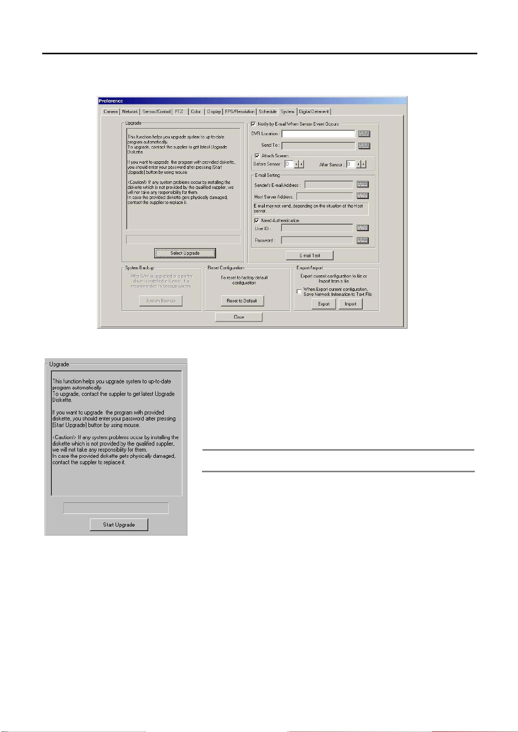
65
6.9 System
6.9.1. Upgrade
Use CD-R or USB storage device for program upgrade in the DVR.
Below is the way to install automatically.
1. Press [Start Upgrade] button.
2. Select a folder that has the programs (Disk1).
3., Insert the disk or the drive and click on the executable file.
4. When the installation is finished, the system will automatically reboot.
Note Do not forget to press the System Backup button after system
upgrade had been done.
Page 66

66
6.9.2. Notify by E-mail When Sensor Event Occurs
When this box is chosen, e-mail will be sent to the mailbox when there is
sensor event.
DVR Location
Input the name of the DVR
Send To
Input the address of the recipient. Then, the e-mail will be sent to the first
address and the e-mails from second address will be sent to BCC(Blind
Carbon Copy).
Attach Screen
Set to change the image of frame to JPG format before attaching the image.
File may not be attached and only the sensor alarm may be sent when the file
is protected with password.
Total images attached will be [Before Sensor + After Sensor + 1 (while sensor
event)].
1. Before Sensor: From the beginning of sensor alarm, set the frames for
images those are recorded previously.
2. After Sensor: From the beginning of sensor alarm, set the frames for
images those are recorded later.
3. When both “Before Sensor” and “After Sensor” items are 0, only the first
frame of the sensor activation period will be attached.
Setting E-mail
1. Address of the Sender: Input the address of the sender. Input the mail
address according to “Host Server Address”.
2. Host Server Address: Input the server address.
Require Authentication
According to the type of the server, the server will require authentication.
When the server require authentication, select “Need Authentication” box and
fill in “User ID” and “Password” category.
E-mail Test
Send e-mail for test.
Page 67
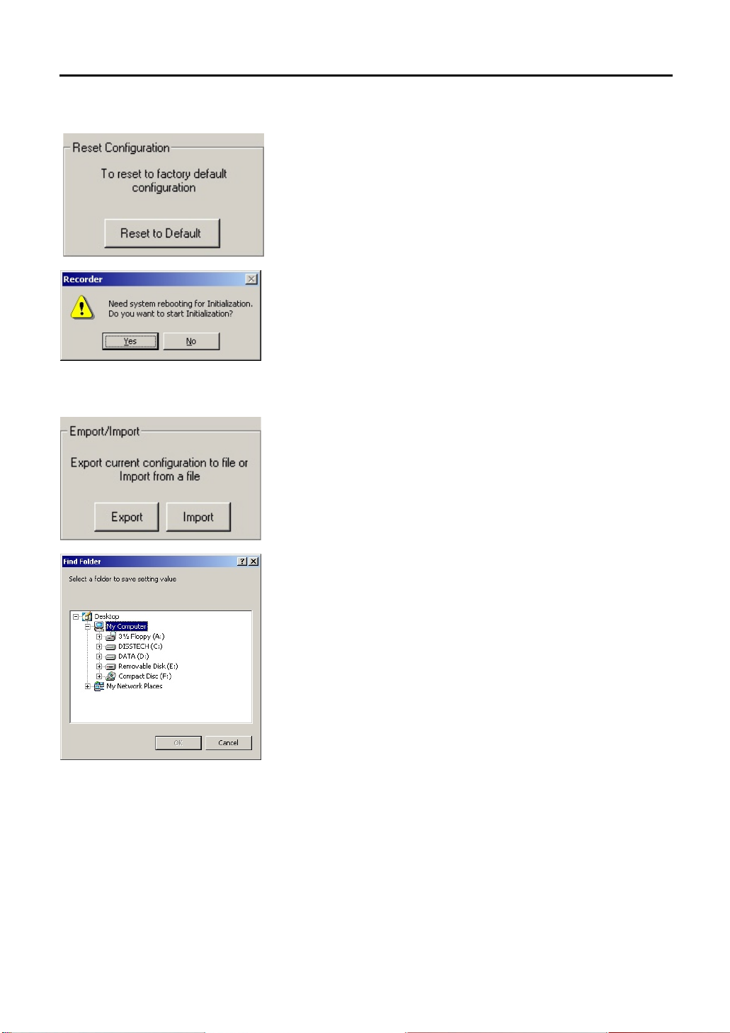
67
6.9.3. Reset Configuration
Click the [Initialization] button and all the setting will go back to default.
6.9.4. Export/Import
Export
Save setting value of the DVR to a disk.
Import
Call up the saved setting values and set the value. The system reboots while
this functions.
Page 68
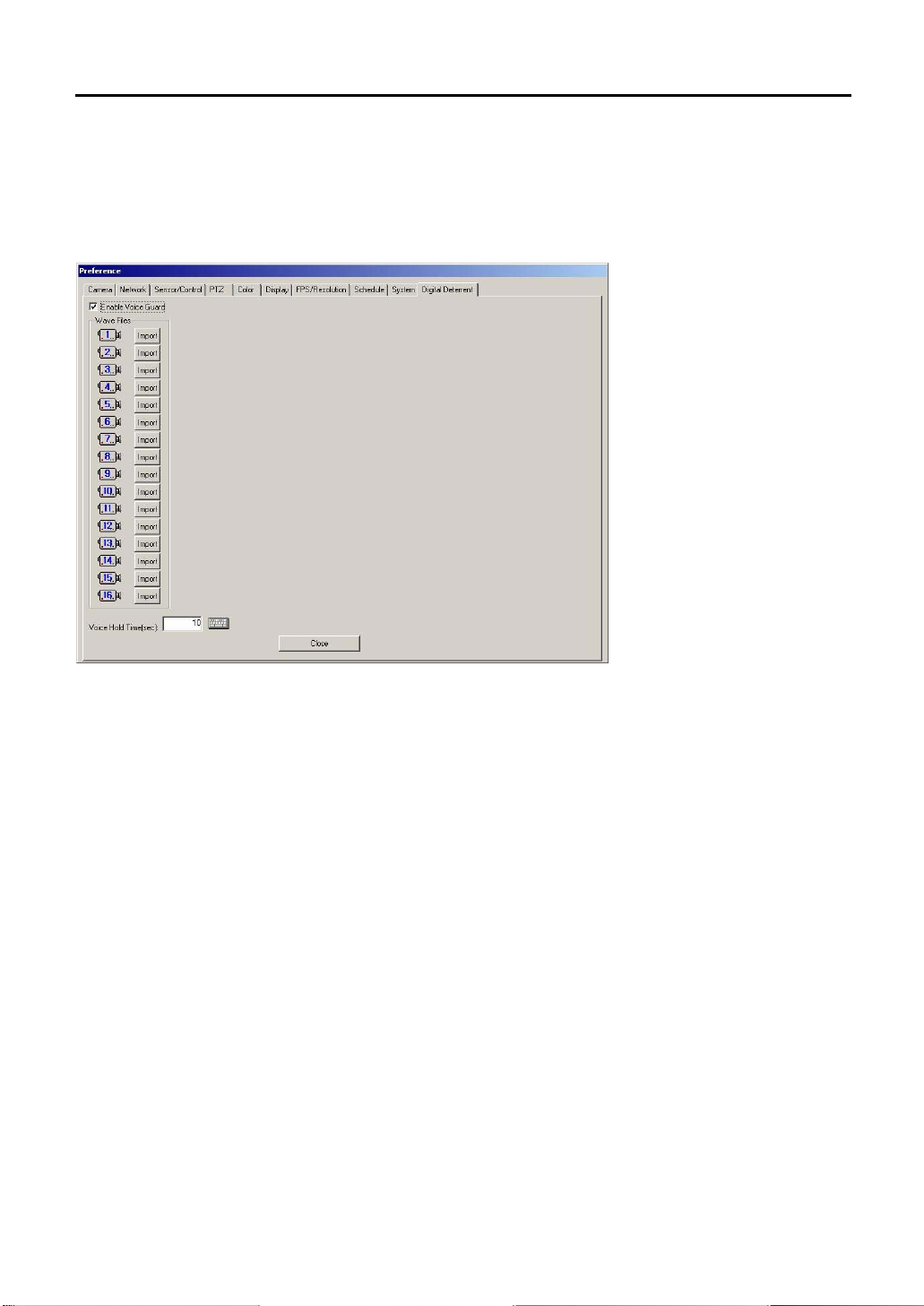
68
6.10 Digital Deterrent
You can hear sound of the stored WAV file when ‘ Enable Voice Guard’ is checked and a motion sensor is operating.
Import You can also store the WAV file of each channel separately by clicking ‘ Import’ button.
Voice Hold Tim: Upon selecting ‘ voice hold time’ , you can only hear the sound of first active camera even when
several motion sensors become active between selected time interval (in sec). When the selected time (sec) interval
lapses, you can hear the sound of next camera.
Page 69
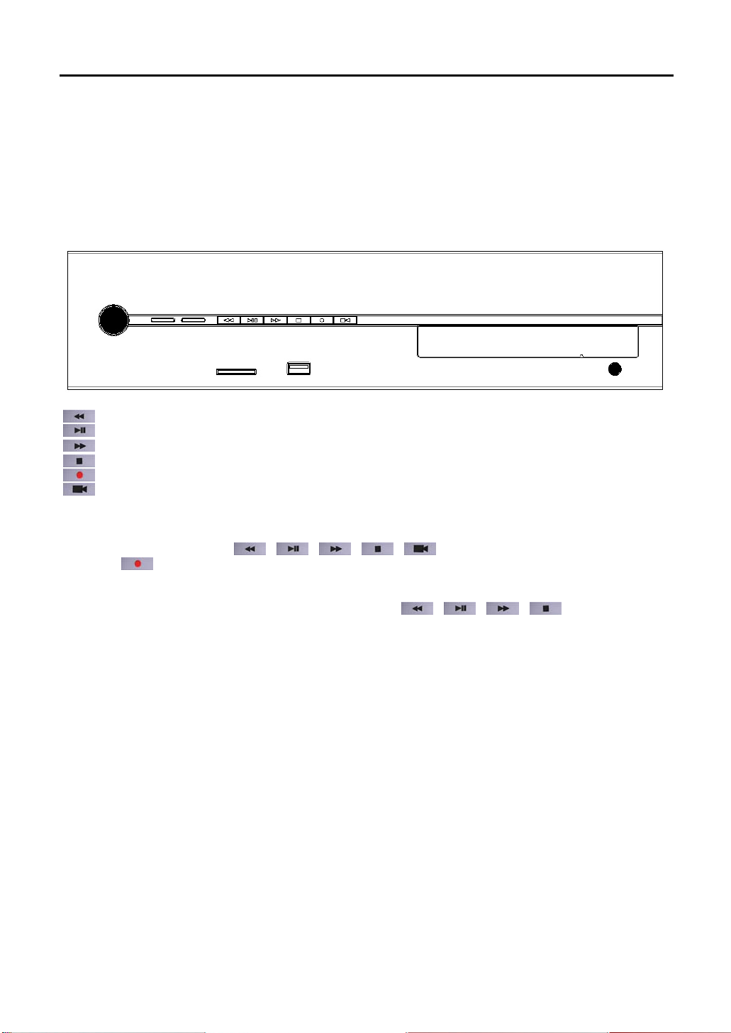
69
7. Instant Playback
This is a feature, ideal for users, who are familiar with a VCR. By using VCR buttons, you can quickly and
conveniently search and play stored video files. In addition, it provides a feature that enables (file) backup to a
preferred media (USB memory stick/ memory card/CD) while searching and playing video files. In other words,
you can simultaneously watch video images of selected record time from a selected camera, and you can record
the same images to CD, USB or memory card
.
.
] REW - Rewind
[
] P/P – Play or Pause
[
] FF – Fast Forward
[
[
] STOP - Stop
[
] REC - Record
] CAM - Camera
[
7.1 VCR Mode
At live watch view, if you press [ ][ ][ ][ ][ ] buttons, a list appears in VCR mode. If
you press [
is 1) in the live watch view while recording it to a selected media. In this case, it is on VCR Record Mode. In VCR
mode, you cannot able to use a mouse and keyboard. Play/record time starts on the hour, currently stored for the
channel. From menu, displayed in each pop-up window, each [
as [up][select][down][close].
] button, DVR plays the lowest numbered channel (ex: from number 1 to 16, the lowest number
][ ][ ][ ] button functions
Page 70
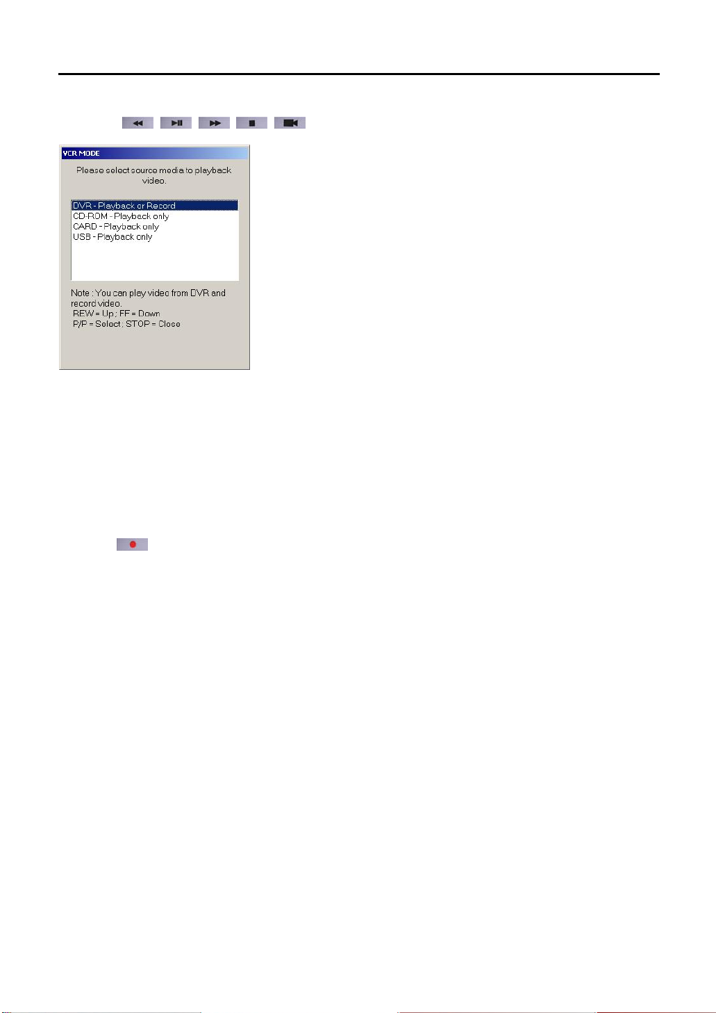
70
7.1.1. When [
][ ][ ][ ][ ] buttons are pressed.
1) DVR – Playback or Record: In “ VCR Play and Record Mode” , DVR plays back stored video files. If you
prefer, you can record currently playing video files to other media. First view being played should be the lowest
among recorded channels.
2) CD-ROM – playback only: enters “ VCR play mode” . Only when you have a video file in the CD-ROM, can
you play the CD-ROM. You can only make a playback and cannot record the video file to other storage devices
3) Card – playback only: enters “ VCR play mode” . Only when you have a video file in the memory card, can
you play the video file in the memory card. You can only make a playback and cannot record the video file to
other storage devices.
4) USB – playback only: enters “ VCR play mode. Only when you have a video file in the USB, can you play the
video file in the USB. You can only make a playback and cannot record the video file to other storage devices
7.1.2. When [
The lowest channel is played from the current live watch view while recording begins. In this case, you are in VCR
record mode.
]button are pressed.
Page 71
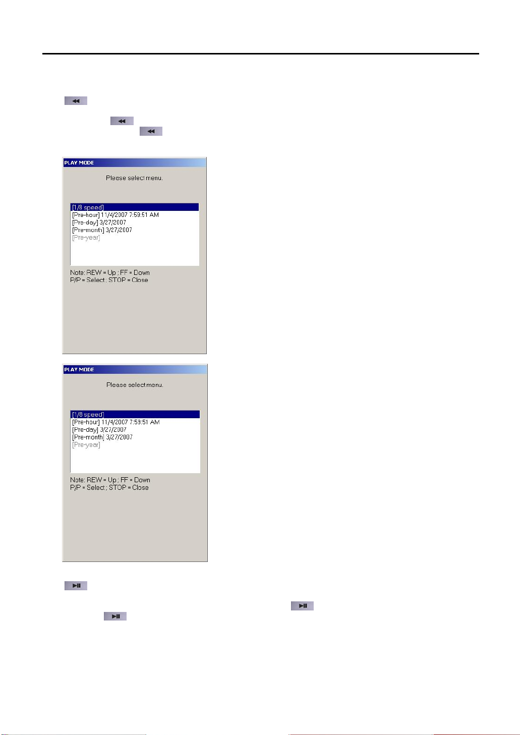
71
7.2 VCR Playback and Record Mode
7.2.1. [
] Rewind
If you press [
speed). If you press [
8x speed, you can select 1/8x speed, previous hours, previous day, previous month, previous year. After 1/8x speed
follows 1/4x, 1/2x, 1x, 2x speed.
] button in playback view, the stored files are played backward at twice the normal speed (2x
] again, it will play backward four times (4x) to eight times (8x) the normal speed. After
7.2.2. [
] Play or Pause
While the video file is being played in the playback view, press [
you press [
] button while the video is pause, the video file is played at normal speed.
] button and the video temporarily pauses. If
Page 72
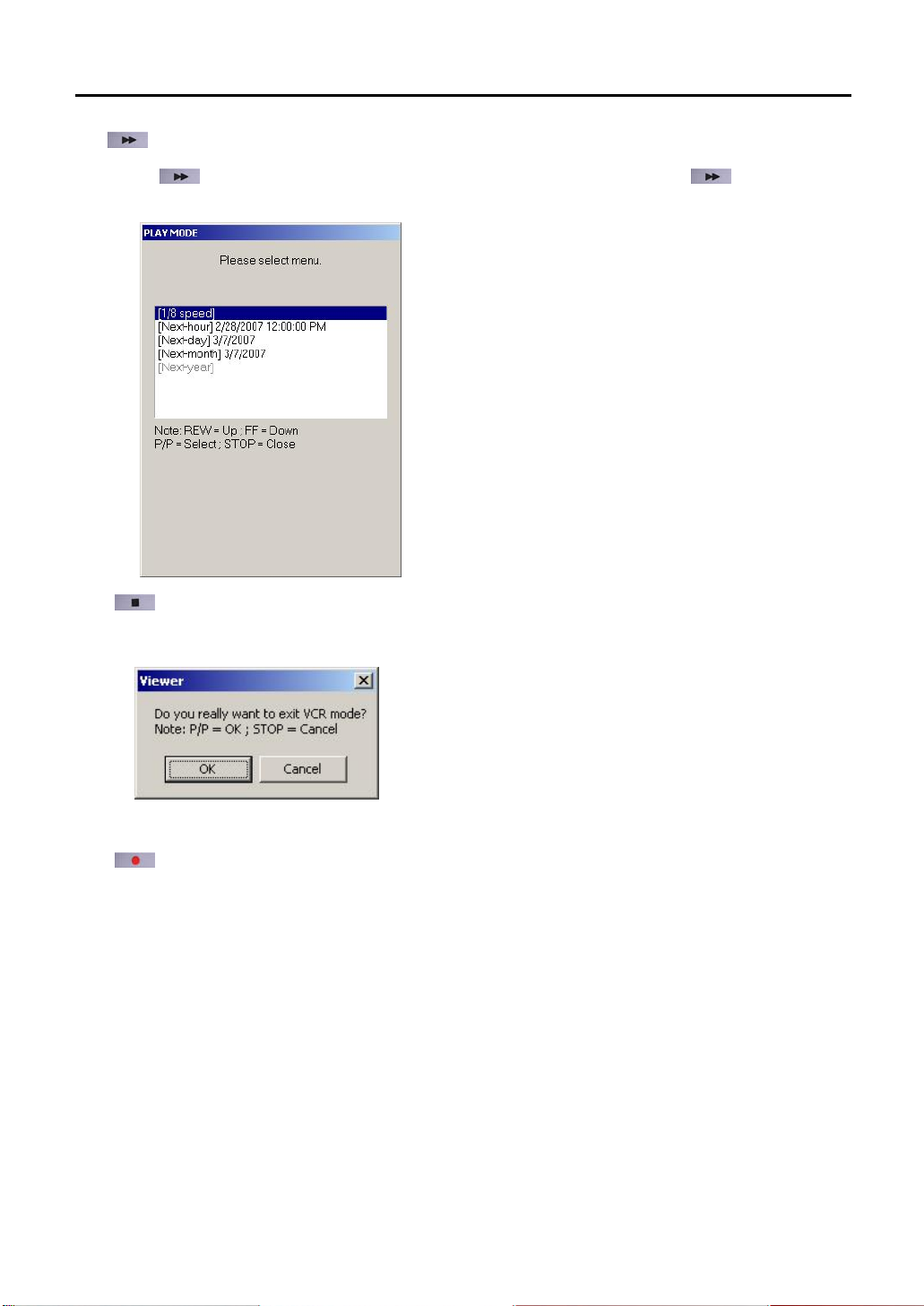
72
7.2.3. [
] Fast Forward
Press [
more, and video data is played forward at 4x, 8x speed. After 8x speed, you can select 1/8x, next hour, next day,
next month, next year. The selection AFTER 1/8x is 1/4x, 1/2x, 1x, 2x SPEED.
] button in playback view, and stored video data is played at 2x speed. Press [ ] button once
7.2.4. [
7.2.5. [
] Stop
a) In playback view, VCR mode ends.
.
b) After record starts, the record stops.
] Record
Enters VCR record mode, you can record the searched video file into any storage device: CD-ROM,
USB-Memory, Memory card)
Page 73
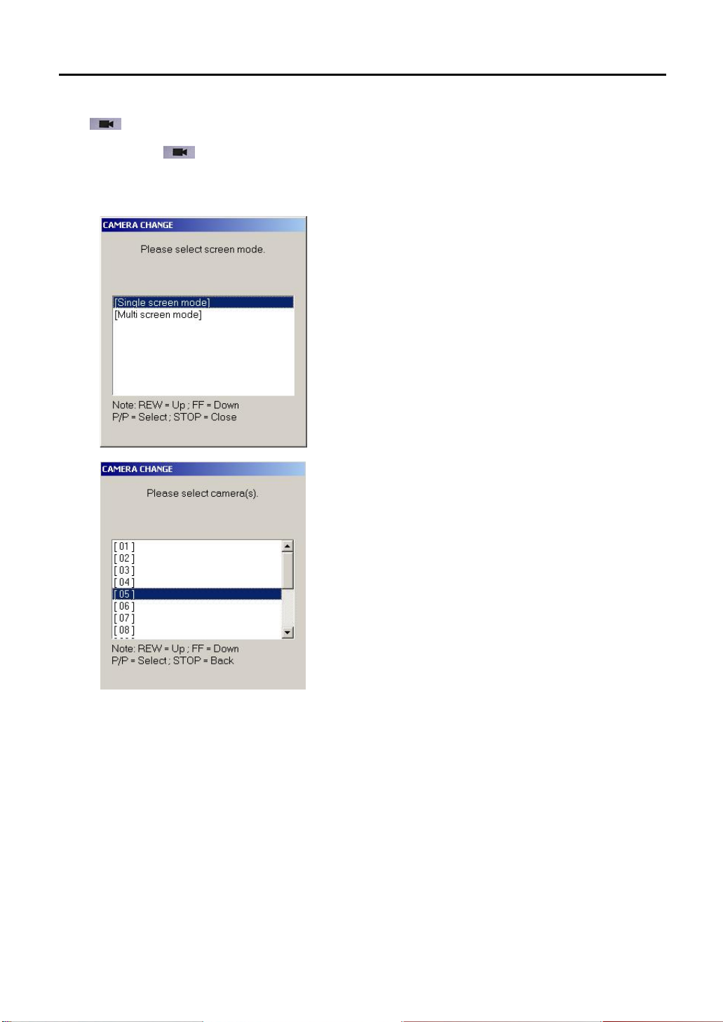
73
7.2.6. [
] Camera
If you press [
[Multi-screen mode], appears. If you select [Single screen mode], you can watch one screen, and if you select
[Multi screen mode], you can watch screens in numbers of 4, 9 and 16.
a) Select single channel
] button in playback view, a window, where you can select [Single screen mode] and
Page 74

74
b) Select multi-channels
Page 75

75
7.3 VCR Record Mode
a) When you press [
DVR. Upon selecting the desirable storage media, the recording begins.
] button, a list appears for the possible storage media you can record in current
b) When the recording begins, a “ REC” sign in red appears in top right corner of the screen.
c) If you wish to stop the recording, press a [
buttons don’ t work. Only the [
] button. During recording, [ ], [ ], [ ], [ ]
] button works.
Page 76

76
7.4 VCR Playback Mode
In VCR Play Mode, [
file directory appears for your selection. Afterward, you will need to press [
When you press [
viewer closes.
], [ ] buttons cannot be used, and you can only watch one channel. At initial play, a
] button in order to see a file directory.
] button, [OPEN FILELIST] and [EXIT VIEWR] appears. When you select [EXIT VIEWER], the
Page 77

77
8. APPENDIX
8.1 Pin Assignment of Alarm Port
Refer to the pictures for connecting the pin assignment of alarm port. (DVR-PC8 Series)
Refer to the pictures for connecting the pin assignment of alarm port. (DVR-PC16 Series)
Alarm In: 4, Alarm Out: 2
<Pin Assignment> <Pin Description>
※ -Sub connector on the rear panel is male straight type.
<Caution> D
Page 78

78
Block Diagram for Alarm Input
Block Diagram for Alarm Out
1. Sensor Input: Normal Open (N/O), Normal Close (N/C)
2. Line impedance of cables should be less than 20Ω.
1. Alarm Out: Normal Open (N/O)
2. Maximum should be under DC24V 2A.
8.2 TCP/IP Port Setting Method using the firewall.
There is a firewall between the DVR-PC8/16 Series and remote sites. Remote site computer usually uses internet or
private line to connect with the DVR-PC8/16 Series (protected by firewall equipment). According to the setting of the
firewall, it could not be connected but if the firewall equipment are set as below, the connection would be made. The
content for each port number is the usage of each port
TCP/IP
Port
(Each port number is fixed)
Note In case of using the NAT from the firewall or router equipment, no problem will occurs when external IP
1. Log-in connection: 7000
2. Transmission for live viewing: 8000, 8001
3. Transmission for remote playback: 9000, 9001
4. Connection for server diagnosis: 8002
5. Transmission for alarmed video notification: 8003
6. Time synchronization: 3000
7. (Multicast protocol port,IP = 230.255.255.255)
8. SMTP for e-mail event notification: 25
9. Two-Way Audio: 7010, 7011
Assign the Log-In port manually and the DVR will automatically assign consecutive ports for the remaining
functions listed on the left.
address is changed to internal IP address (ex. 192.168.x.x),
 Loading...