

Page 1

OPERATION / INSTALLATION MANUAL
200 New Highway, Amityville, NY 11701
www.specotech.com
!Speco Technologies is constantly developing product improvements.
We reserve the right to modify product design and specifications
without notice and without incurring any obligation. Rev. 4/28/10
Page 2
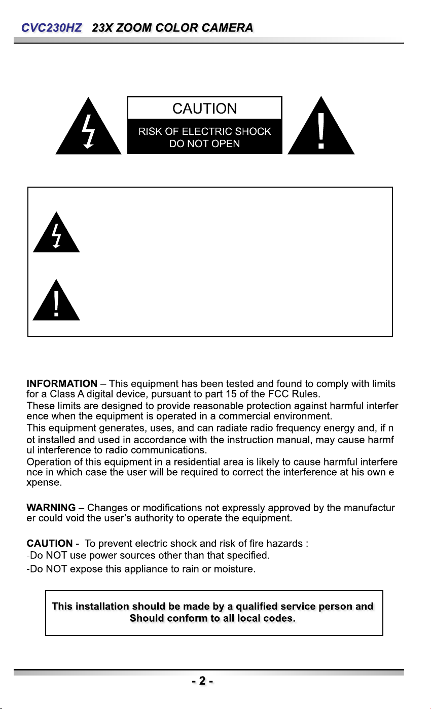
The lightning flash with an arrowhead symbol, within an
equilateral triangle is intended to alert the user to the presence
of uninsulated dangerous voltage within the product’s enclosure
the may be of sufficient to constitute a risk of electric shock to
persons.
The exclamation point within an equilateral triangle is intended
to alert the user to the presence of important operating and mai
nt e na n ce (s er v ic i ng ) i n st ru c ti o ns in t h e l it e ra t ur e
accompanying the appliance.
Page 3
Page 4
Page 5
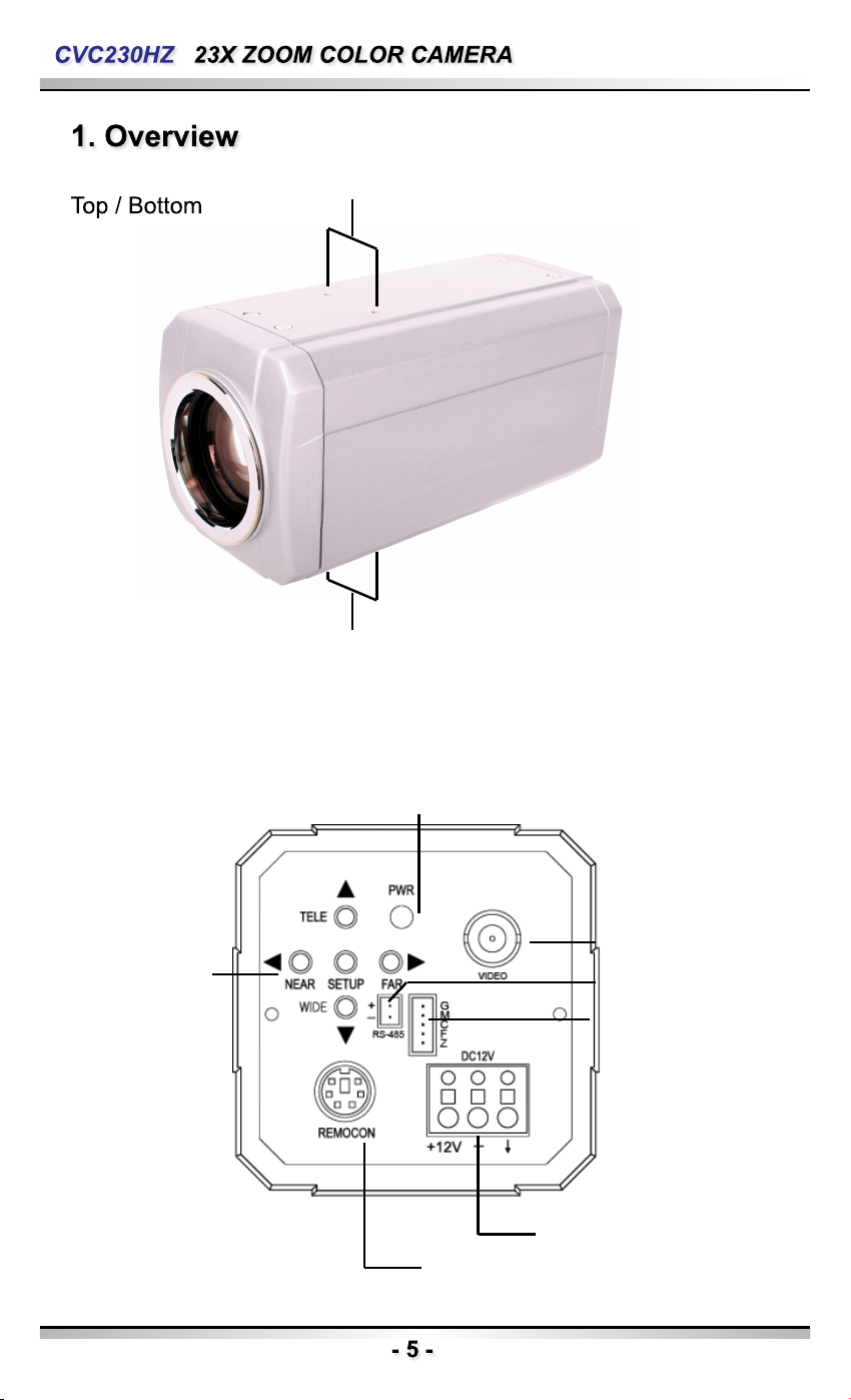
Back
1) Camera mounting screw hole
2) Camera mounting screw hole
4) Power LED
3) Key Buttons
5) Video Output Jack
6) RS-485
7) External Control
Connector
9) Power Input Terminal
8) Communication Control Connector
Page 6

1. Top Mounting Bracket Screw Hole
Used to fix tripod mounting bracket on top of the camera.
2. Tripod Mounting Hole
Used to install the camera on an optional tripod.
The tripod must be equipped with screws with specifications
shown on the right.
3. Key Buttons
Following buttons control zoom, focus, and auto focus functions.
WIDE button
TELE button
F-NEAR button
F-FAR button
AF button
: To widen the view. (ZOOM OUT)
: To close in on a far object. (ZOOM IN)
: To see a near object clearly.
: To see a far object clearly.
: To activate auto focus just once.
Pressing the ‘SET’ button locks the zoom control function of
these buttons and prompts the main setup menu.
*The zoom position is saved after 5 seconds when you set zoom function.
Main setup menu can be navigated using these buttons.
SET : To access the main setup menu.
UP (WIDE button)
Down (TELE button)
LEFT ( F-NEAR button)
RIGHT (F-FAR button)
: To Move the arrow indicator to up.
: To Move the arrow indicator to down.
: To Move the arrow indicator to left.
: To Move the arrow indicator to right.
4. Power LED
Illuminates when power is supplied.
5. Video Output Jack
Used to connect an external video monitor in jack.
6. RS-485
Includes the RS-485 communication pin
Page 7
7. External Control connector
Relaters to the motion detection output signal.
Zoom and focus functions can be controlled using external
signals.
8. Communication Control Connector
Used to connect the Remote Controller (Option).
9. Power Input Terminal
Power supply terminal
+ Connection methods may vary depending on the video equipment.
Please refer to the model specific instruction manual.
+ Connect cables with the unit powered down.
+ Set the 75Ω / Hi-Z selection switch as shown below if you have an
intermediate device.
75Ω Hi-Z 75Ω Hi-Z
Page 8
2) Connecting to Power
Each model has a different power input specification.
Please check the model type and standard power requirement before connecting to power.
+ Communication Control Connector Pin Description.
Number Name Number Name
1 Right 4 Auto Focus
2 Left 5 Down
3 Setup 6 Up
Page 9
MAIN SETUP MENU
CAM TITLE OFF ON
WHITE BALANCE ATW(OUTDOOR)
BACKLIGHT OFF
HIGH
MOTION DET OFF
FOCUS MODE
ZOOM SPEED
DISP ZOOM MAG
LENS INIT
EXPOSURE BRIGHTNESS
AGC
END
SPECIAL USER PRESET
DAY/NIGHT
COMM ADJ
RESET
EXIT
AWCSET
LOW
ZOOM TRK
D-ZOOM
ZOOM POS INIT
END
IRIS
SSNR
PRIVACY
DIS SYNC
IMAGE ADJ
MANUAL
MIDDLE
SHUTTER
SENS-UP
END
Page 10

Use the six buttons on back of the camera
Up button
SET button
LEFT button
RIGHT button
DOWN button
1. Press the SET button to access the main setup mode.
- Main setup menu is displayed on the monitor screen
MAIN SETUP
▶
CAM TITLE
WHITE BAL
BACKLIGHT
MOTION DET
FOCUS
◀┘
EXPOSURE
◀┘
SPECIAL
RESET
EXIT
◀┘
OFF
ATW
OFF
OFF
◀┘
2. Select the desired feature using the UP or DOWN button.
- Each pressing of the UP or DOWN button moves the indicator to the nest or previous
feature.
- Move the arrow indicator to the desired feature item.
MAIN SETUP
Select feature
using the UP
or DOWN button.
▶
CAM TITLE
WHITE BAL
BACKLIGHT
MOTION DET
FOCUS
EXPOSURE
SPECIAL
RESET
EXIT
◀┘
◀┘
◀┘
OFF
ATW
OFF
OFF
◀┘
Change the status
using the LEFT
or RIGHT button.
Page 11

3. Change the status of the selected feature using the LEFT or RIGHT button.
4. When completed, move the arrow indicator to ‘EXIT’ and press the SET button.
Use this feature to designate a name for the camera, which will display on the
monitor screen.
1. Press the SET Button to display the main setup menu and move the arrow indicator to
‘CAM TITLE’ using the UP or DOWN button.
2. Set ‘CAM TITLE’ to ‘ ON’ using the LEFT or RIGHT button.
MAIN SETUP
3. Press SET button.
▶
CAM TITLE SETUP
ABCDEFGHIJKLMNO
PQRSTUVWXYZabcd
e f g h i j k l m n o p q r s
Tuv w x y z 0 1 2 3 4 5 6 7
89( ) < > - / # ! ? , .
CLR POS END
CAM TITLE
WHITE BAL
BACKLIGHT
MOTION DET
FOCUS
◀┘
EXPOSURE
◀┘
SPECIAL
RESET
EXIT
◀┘
OFF
ATW
OFF
OFF
◀┘
Page 12

4. You can enter up to 20 characters.
1) Move the cursor to the character entry field using the LEFT or RIGHT button.
2) Use UP, DOWN, LEFT, and RIGHT buttons to select a desired character.
CAM TITLE SETUP
ABCDEFGHIJKLMNO
PQRSTUVWXYZabcd
e f g h i j k l m n o p q r s
Tuv w x y z 0 1 2 3 4 5 6 7
89( ) < > - / # ! ? , .
CLR POS END
3) Press the SET button to confirm selection of the blinking character. The character is
then saved, and the cursor in the entry field moves to the next position.
4) Repeat steps 1) through 3) until the desired name has been entered.
5. Select on screen position of the CAM TITLE.
1) Move the cursor to ‘POS’ and press SET button.
CAM TITLE SETUP
ABCDEFGHIJKLMNO
PQRSTUVWXYZabcd
efghijklmnopqrs
Tuv w x y z 0 1 2 3 4 5 6 7
89( ) < > - / # ! ? , .
CLR POS END
2) The CAM TITLE is displayed on the top-left of the monitor screen.
(Default position)
3) Select the position by using the 4-directional buttons, then press the SET button to confir
m
the position.
6. When completed, move the cursor to ‘END’ and press SET button.
Page 13

Your camera provides three ‘WHITE BAL’ control modes for your choosing in
Adjusting the white balance.
1. Press the SET button to access the main setup menu and move the indicator to ‘WHITE BAL’
using the UP or DOWN button.
2. Set ‘WHITE BAL’ using the LEFT or RIGHT button.
MAIN SETUP
CAM TITLE
▶
WHITE BAL
BACKLIGHT
MOTION DET
FOCUS
EXPOSURE
SPECIAL
RESET
EXIT
◀┘
◀┘
◀┘
OFF
ATW
OFF
OFF
◀┘
The three white balance control modes are as follows :
◈ ATW (Auto Tracking White Balance) :
- OUTDOOR : This mode can be used within the color temperature
range 1,800~10,500K
(Ex: fluorescent light, outdoor, sodium vapor lamp or inside tunnels)
- INDOOR : This mode can be used within the color temperature range
3,000K~10,500K
◈ AWC (Auto White balance Control) :
The white balance is automatically adjusted in a specific environment. In
order to obtain the best result, press the SET button while the camera
focuses
◈ Manual :
To fine adjust, select the Manual mode. You can increase or decrease
the red or blue factor while monitoring the difference on the screen. Set to
‘MANUAL’ mode and press the SET button. Increase or decrease the
value for red (R-Gain) and blue (B-Gain), watching the color of the picture,
and press the SET button when you obtain the best color.
Page 14

When there is a strong backlight behind the object, clear images of the
background as well as the object can still be obtained by using the BACKLIGHT
function.
1. Please position the arrow to point to ‘BACKLIGHT’ on the SETUP menu by using the UP
and DOWN buttons.
2. Please select the mode you wish to operate by pressing the LEFT or RIGHT button.
MAIN SETUP
CAM TITLE
WHITE BAL
▶
BACKLIGHT
MOTION DET
FOCUS
EXPOSURE
SPECIAL
RESET
EXIT
◀┘
◀┘
◀┘
OFF
ATW
OFF
OFF
◀┘
◈ HIGH/MIDDLE/LOW: You can adjust the sensitivity of Backlight Compensation.
◈ OFF: BACKLIGHT function does not operate.
This product has a feature that allows you to observe movement of objects in
4 different areas on the screen, and the words ‘MOTION DETECTED’ appear o
n the screen when movement is detected; hence a single individual can condu
ct supervision efficiently, The camera detects an object’s movement by sensing
disparity of outline, and level of brightness and color. The camera receives det
ection signal from MD output terminal.
MD SETUP
▶
DISP ALARM
AREA SEL
AREA MODE
TOP
BOTTOM
LEFT
RIGHT
END
OFF
AREAL
ON
IIIIIIIIIIIIIIIIII
10
IIIIIIIIIIIIIIIIII
50
IIIIIIIIIIIIIIIIII
10
IIIIIIIIIIIIIIIIII
50
Page 15

+ Please press the SETUP button.
- OFF : MOTION DETECTION mode is cancelled.
- ON : Any motion in the selected areas is observed.
+ Please press the SETUP button.
- OFF : MOTION DETECTION mode is cancelled.
- ON : Any motion in the selected areas is observed.
+ Please select the area you wish to observe from the 4 areas in AREA SEL
mode.
+ Please select ON mode for the chosen area.
+ Please adjust the size of the area to be observed by using the UP, DOWN,
LEFT or RIGHT button.
+ Please press the SETUP button to save changes and complete the setting.
MAIN SETUP
CAM TITLE
WHITE BAL
BACKLIGHT
MOTION DET
▶
FOCUS
EXPOSURE
SPECIAL
RESET
EXIT
◀┘
◀┘
◀┘
OFF
ATW
OFF
OFF
◀┘
1. Press the SET button to access the main setup menu and then position
the indicator over FOCUS using the UP or DOWN button.
2. Press the SET button.
MODE: You can select the most suitable zoom mode. Move the arrow
indicator to ‘MODE’ using UP or DOWN button.
FOCUS SETUP
▶
MODE
ZOOM TRK
ZOOM SPEED
D-ZOOM
DISP ZOOM MAG
ONE-PUSH
ON
FAST
OFF
ON
◀┘
+ AUTO: Select auto and press the SET button to confirm. Increase or decre
ase optical zoom (ZOOM) or digital zoom (D-ZOOM) positions usin
g the UP or DOWN button while verifying the changes on screen. E
nabling D-ZOOM(ON) means that digital zoom will activate once op
tical zoom ends. Focus is automatically adjusted with moving zoom.
Page 16

+ ONE PUSH: Focus is automatically adjusted just once, after zoom position is
changed. Select ‘ONE PUSH’ and press the SET button to conf
irm. Increase or decrease optical zoom (ZOOM) or digital zoom
(D-ZOOM) positions using the directional buttons while verifying
the changes on screen. Press the SET button once desired ima
ge quality is obtained.
+ MANUAL: Select ‘MANUAL’ and press the SET button to confirm. Increase
or decrease optical zoom (ZOOM) or digital zoom (D-ZOOM) p
ositions using the directional buttons while verifying the changes
on screen. Press the SET button once desired image quality is
obtained. Focus can be manually adjusted, independent of movi
ng zoom.
ZOOM TRK: You can select to use ‘ZOOM TRK’. Move the arrow indicator to
‘ZOOM TRK’ using UP or DOWN button. Set ‘ZOOM TRK’ to on
using LEFT or RIGHT button.
FOCUS SETUP
MODE
▶
ZOOM TRK
ZOOM SPEED
D-ZOOM
DISP ZOOM MAG
ONE-PUSH
ON
FAST
OFF
ON
◀┘
Configure zoom tracing speed using this feature. Position the
indicator over ‘ZOOM SPEED’ using the UP or DOWN button
and then set to desired mode using the LEFT or RIGHT butto
n
MODE
ZOOM TRK
▶
ZOOM SPEED
D-ZOOM
DISP ZOOM MAG
* FAST : To move zoom fast.
FOCUS SETUP
ONE-PUSH
ON
FAST
OFF
ON
* SLOW : To move zoom slowly.
◀┘
Page 17

D-ZOOM : Configure magnification limit from x2~x10 using this feature. Po
sition the indicator over ‘D-ZOOM’ using the UP or DOWN butto
n. Set ‘D-ZOOM’ to ‘ON’ and press the SET button to confirm.
FOCUS SETUP
MODE
ZOOM TRK
ZOOM SPEED
▶
D-ZOOM
DISP ZOOM MAG
ONE-PUSH
ON
FAST
ON
ON
◀┘
Set ‘ZOOM LIMIT’ to the desired level using the LEFT or RIGHT button.
DISP ZOOM MAG: Use this feature to display the current zoom magnification
level on screen. Position the indicator over ‘DISP ZOOM
MAG’ using the UP or DOWN button. Then set to ON usin
g the LEFT or RIGHT button.
FOCUS SETUP
MODE
ZOOM TRK
ZOOM SPEED
D-ZOOM
DISP ZOOM MAG
▶
ZOOM POS INIT
LENS INIT
END
ONE-PUSH
ON
FAST
OFF
ON
OFF
ON
◀┘
ZOOM POS INIT: Moves to the controlled ZOOM position when the power t
urned on and is a function of the initial ZOOM position co
ntrol
FOCUS SETUP
MODE
ZOOM TRK
ZOOM SPEED
D-ZOOM
DISP ZOOM MAG
ZOOM POS INIT
▶
LENS INIT
END
ONE-PUSH
ON
FAST
OFF
ON
ON
ON
◀┘
Page 18

LENS INIT: Use this feature to initialize the lens. Position the indicator over L
ENS INIT. Using the UP or Down button. Press the SET button to
confirm.
FOCUS SETUP
MODE
ZOOM TRK
ZOOM SPEED
D-ZOOM
DISP ZOOM MAG
ZOOM POS INIT
▶
LENS INIT
END
ONE-PUSH
ON
FAST
OFF
ON
OFF
ON
◀┘
END: To revert to the main setup menu.
EXPOSURE SETUP
BRIGHTNESS
▶
IRIS
SHUTTER
AGC
SSNR
SENS-UP
END
50 …………
AUTO
--MIDDLE
MIDDLE
◀┘
AUTO
1. Press the SET button to access the main setup menu and then position
the indicator over ‘EXPOSURE’ using the UP or DOWN button.
2. Press the SET button to confirm.
BRIGHTNESS: Use this feature to adjust image brightness. Position the in
dicator over ‘BRIGHTNESS’ using the UP or DOWN button
. Then increase or decrease brightness level using the LEF
T or RIGHT button while verifying the changes on screen.
Set END once desired level is obtained.
EXPOSURE SETUP
BRIGHTNESS
▶
IRIS
SHUTTER
AGC
SSNR
SENS-UP
END
50 …………
AUTO
--MIDDLE
MIDDLE
◀┘
AUTO
Page 19

IRIS: Set ‘IRIS’ to ‘AUTO’ or ‘MANUAL’. Position the indicator over ‘IRIS’ us
ing the UP or DOWN button and then select the desired iris mode usi
ng the LEFT or RIGHT button.
EXPOSURE SETUP
BRIGHTNESS
IRIS
▶
SHUTTER
AGC
50 …………
AUTO
--MIDDLE
- AUTO : The iris is automatically activated upon illumination.
- MANUAL : Manual iris configuration. Set ‘IRIS’ to ‘MANUAL’ using
the LEFT or RIGHT button and then press the SET button.
Increase or decrease iris level using the LEFT or RIGHT
button while verifying the changes on screen.
SHUTTER: Control image brightness by adjusting shutter speed.
1. Position the indicator over ‘SHUTTER’ using the UP or DOWN button.
Then select the desired shutter mode (A.FLK, ESC, MANUAL) using
the LEFT or RIGHT button
EXPOSURE SETUP
BRIGHTNESS
IRIS
▶
SHUTTER
AGC
50 …………
AUTO
--MIDDLE
- A.FLK (NTSC: 1/100, PAL: 1/120): Flicker-free mode
- ESC: Automatic shutter speed setting (optimal)
- MANUAL: Manual shutter speed setting
2. If you choose ‘MANUAL’, select the optimal shutter speed.
In MANUAL mode, the optimal shutter speed needs to be designated.
Select from 1/60 to 1/120,000(NTSC) or from 1/50 to 1/120,000 (PAL)
* ‘Sens-up’ mode con be configured manually (2x to 128x).
Verify changes made to the shutter speed by referencing to changes in on screen
brightness.
3. Press the SET button to complete.
Page 20

AGC (Auto Gain Control) : For brighter images.
1. Position the indicator over ‘AGC’ using the UP or DOWN button.
2. Set ‘AGC’ to the desired mode using the LEFT or RIGHT button.
- HIGH
- MIDDLE
- LOW
- OFF
: Wide range gain value adjustment
: Middle range gain value adjustment
: Narrow range gain value adjustment
: Disabled
EXPOSURE SETUP
BRIGHTNESS
IRIS
SHUTTER
▶
AGC
SSNR
SENS-UP
END
50 …………
AUTO
--MIDDLE
MIDDLE
◀┘
AUTO
SSNR (Super Noise Reduction) : On screen noise reduction.
1. Position the indicator over ‘SSNR’ using the UP or DOWN button.
2. Set ‘SSNR’ to the desired mode using the LEFT or RIGHT button.
- LOW
- MIDDLE
- HIGH
- OFF
: Low noise reduction
: Medium noise reduction
: High noise reduction
: Disabled
EXPOSURE SETUP
BRIGHTNESS
IRIS
SHUTTER
AGC
▶
SSNR
SENS-UP
END
50 …………
AUTO
--MIDDLE
MIDDLE
◀┘
AUTO
Page 21

SENS-UP : This feature ensures clear images at night or under low lighting
conditions.
1. Position the indicator over ‘SENS-UP’ using the UP or DOWN button.
2. Set ‘SENS-UP’ to the desired mode using the LEFT or RIGHT button.
- AUTO
- OFF
: Select this mode for use in night time or under low lighting
conditions.
: Disabled
EXPOSURE SETUP
BRIGHTNESS
IRIS
SHUTTER
AGC
SSNR
SENS-UP
END
50 …………
AUTO
--MIDDLE
MIDDLE
◀┘
AUTO ▶
SPECIAL SETUP
USER PRESET
▶
PRIVACY
DAY/NIGHT
DIS
SYNC
COMM ADJ
IMAGE ADJ
END
◀┘
◀┘
OFF
OFF
COLOR
OFF
INT
◀┘
1. Press the SET button to access the main setup menu and then position
the indicator over ‘SPECIAL’ using the UP or DOWN button.
2. Press the SET button to confirm.
Page 22

USER PRESET:
Preset user-Designated configurations using this feature. Position the indi
cator over ‘USER PRESET’ using the UP or DOWN button and then set to
‘ON’ using the LEFT or RIGHT button. Press the SET button to confirm.
SPECIAL SETUP
USER PRESET
▶
PRIVACY
DAY/NIGHT
DIS
SYNC
COMM ADJ
IMAGE ADJ
END
◀┘
◀┘
OFF
OFF
COLOR
OFF
INT
◀┘
- PRESET NO : Up to eight different preset configurations are supported.
USER PRESET SETUP
PRESET NO.
▶
PRESET MODE
PRESET SAVE
PRESET CLEAR
END
PRESET DEFINED
NO. 1
NO
- PRESET MODE : Configure initial settings under FOCUS, EXPOSURE, etc.
USER PRESET MODE SETUP
FOCUS
◀┘
EXPOSURE
ETC
END
◀┘
◀┘
PRESET DEFINED
Page 23

- PRESET SAVE : Save configured preset.
USER PRESET SETUP
PRESET NO.
PRESET MODE
▶
PRESET SAVE
PRESET CLEAR
END
PRESET DEFINED
NO. 1
NO
- PRESET CLEAR : Clear configured preset.
USER PRESET SETUP
PRESET NO.
PRESET MODE
PRESET SAVE
PRESET CLEAR
▶
END
PRESET DEFINED
NO. 1
NO
- END : Revert to the SPECIAL SETUP menu.
USER PRESET SETUP
PRESET NO.
PRESET MODE
PRESET SAVE
PRESET CLEAR
▶
END
PRESET DEFINED
NO. 1
NO
PRIVACY : Mask privacy area using this feature. The mask area expand /
contract upon the zoom position.
SPECIAL SETUP
USER PRESET
PRIVACY
▶
DAY/NIGHT
DIS
OFF
OFF
COLOR
OFF
◀┘
Page 24

- GROUP SEL
: Choose up to eight groups. Each group can consist of
four mask areas.
- MASK COLOR
- AREA SEL
- AREA MODE
- TOP
- BOTTOM
- LEFT
- RIGHT
: Adjust desired mask color level.
: Configure eight mask areas.
: Mask area display.
: To move the mask area up.
: To move the mask area down.
: To move the mask area left.
: To move the mask area right.
DAY/NIGHT : Select from COLOR, BW or AUTO modes.
SPECIAL SETUP
- COLOR
- B/W
- AUTO
USER PRESET
PRIVACY
▶
DAY/NIGHT
DIS
SYNC
COMM ADJ
IMAGE ADJ
END
◀┘
◀┘
: Color mode.
: BW mode.
: The camera automatically detects lighting conditions and
OFF
OFF
COLOR
OFF
INT
◀┘
selects the mode accordingly.
DIS : The DIS mode can compensate for vibration of the camera.
SPECIAL SETUP
USER PRESET
PRIVACY
DAY/NIGHT
DIS
▶
SYNC
COMM ADJ
IMAGE ADJ
END
◀┘
◀┘
OFF
OFF
COLOR
OFF
INT
◀┘
Page 25

SYNC :
Two synchronization modes are presented,
INTERNAL and EXTERNAL LINE-LOCK.
EXTERNAL LINE-LOCK mode is not available at the moment.
Needed to be upgraded.
SPECIAL SETUP
USER PRESET
PRIVACY
DAY/NIGHT
DIS
SYNC
▶
COMM ADJ
IMAGE ADJ
END
- INT
: Internal synchronization.
- LL
: External line-lock synchronization.
◀┘
◀┘
OFF
OFF
COLOR
OFF
INT
It is not available at the moment.
COMM ADJ :
Use this feature to select communication protocol
(refer to p.46~p.51 for details).
Position the indicator over ‘COMMUNICATION’ using the UP
or DOWN button.
- CAM ID : Assign an ID number to the camera (1 to 255)
Identification number zero is used for Remote controller setup.
◀┘
- DISP CAM ID : Displays camera ID on top left
corner of the screen.
- BAUD RATE : Configure baud rate from 2400 /
4800 / 9600 / 19200 / 38400 /
57600 bps.
- UART MODE : Configure parity bit to NON, EVEN,
or ODD, Data bit is set to 8bit, and
stop bit to 1bit. Set the UART
MODE to EVEN if using the
Remote Controller.
- UART MODE :Used to transfer a packet.
- END
COMMUNICATION SETUP
CAM ID
DISP CAM ID
BAUD RATE
UART MODE
▶
RET PKT
1
ON
9600
8 – N – 1
DISABLE
Page 26

IMAGE ADJ :
Includes image quality or special function factors.
IMAGE SETUP
- FREEZE
- H-REV
- V-REV
- SHARPNESS
PREEZE
H-REV
V-REV
SHARPNESS
COLOR
▶
END
: Use this feature to freeze capture an image.
: Use this feature to horizontally inverse the screen.
: Use this feature to vertically inverse the screen.
: Increasing this value sharpens object edges. Too high of a setting,
ON
OFF
OFF
ON
◀┘
50 llllllllllllllllllllllllllllll
however, produces noise and may obscure the image.
- COLOR
: Adjusting this value affects the chroma level only; the burst level is
unaffected.
END : Evert back to the USER PRESET menu.
To reset your camera to factory default condition.
◀┘
To finish setup menu.
Page 27

MODEL CVC652HZ 23X COLOR ZOOM CAMERA
Signal Format NTSC PAL
Scanning System 2 : 1 Interlace
Pick-Up Device 1/4” Color Sony™ Super-HAD CCD
Total Pixels Number 811 (H) x 508 (V) 795 (H) x 596 (V)
Picture Element 768 (H) x 494 (V) 752 (H) x 582 (V)
S/N Ratio 50dB (AGC Off, Weight On)
Horizontal Resolution Color : 550TV Lines, B/W : 600TV Lines
Lens 23X Zoom, f=3.84 to 88.4mm
Min. Focus Distance 1000mm
D. Zoom OFF/ON (Limit 10X)
Angle field of view
H : Appr. 58.0˚ (Wide) to 2.22˚ (Tele)
V : Appr. 44.8˚ (Wide) to 1.68˚ (Tele)
0.6 Lux (50 IRs) F1.6
Minimum Illumination
0.1 Lux (B/W)
0.004 Lux (Sense-up mode)
Digital Zoom Ration ON / OFF (Limit 10x)
Sync Scanning System 2:1 Interlace
Sync Synchronization Internal
Frequency
Horizontal:15,734KHz /
Vertical : 59.94Hz
Horizontal:15,625KHz /
Vertical : 50.00Hz
OSD (On Screen Display) OSD On / Off
Camera Title ON/OFF (Displayed 20 characters)
Camera ID 255 ID Selectable
Video Output CVBS : 1.0Vp.p / 75Ω
Camera Control RS-485 (2400,4800,9600,19200,38400,57600bps)
Day & Night Auto/Color/ B/W (ICR type)
Page 28

MODEL CVC652HZ 23X COLOR ZOOM CAMERA
Gain Control Low, Middle, High, OFF Selectable
White Balance
Electronic shutter speed
ATW (INDOOR (3,000~10500K),OUTDOOR
(1,800~10,500K)) / AWC / MANUAL
Auto/Manual
(X128 ~ 1/60sec. ~
1/120,000 sec.)
Sense-up Limit
is selectable
Auto/Manual
(X128 ~ 1/50sec.
~ 1/120,000 sec.)
Sense-up Limit
is selectable
OSD Built-in
Motion Detection ON/OFF (Built-in alarm output connector)
SSNR Low / Middle / High / Off Selectable (Noise Control)
Focus Auto / Manual / One Push
Zoom Movement Speed 5.2 Sec : Wide to Tele 5.4 Sec : Wide to Tele
Lens Initialize Built-in
Preset 8-Positions
DIS ON/OFF
On/Off
Privacy Function
(32 Zones, 8 Groups /
4 Programmable Zones per Screen)
FLIP LEFT / RIGHT, UP / DOWN
FREEZE ON/OFF
IRIS Control Auto / Manual
Operation Temperature /
Humidity
-10 ~ 50°C / 30% to 90% RH
Supplied Voltage DC12V ±10% , Max 5W
Power Consumption Max. 4.8W (500mA)
Option Remote Controller (RS-485 type)
 Loading...