

Page 1

INSTRUCTION
MANUAL
SPECO 960H WDR Series
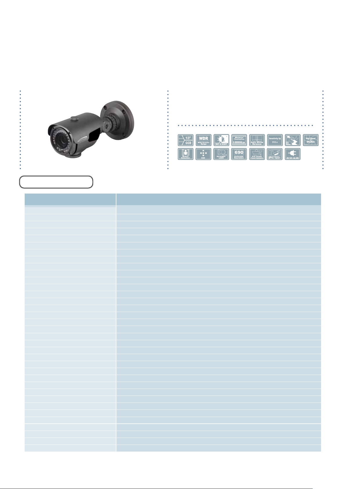
WDRB10H
(Outdoor IR Bullet Camera)
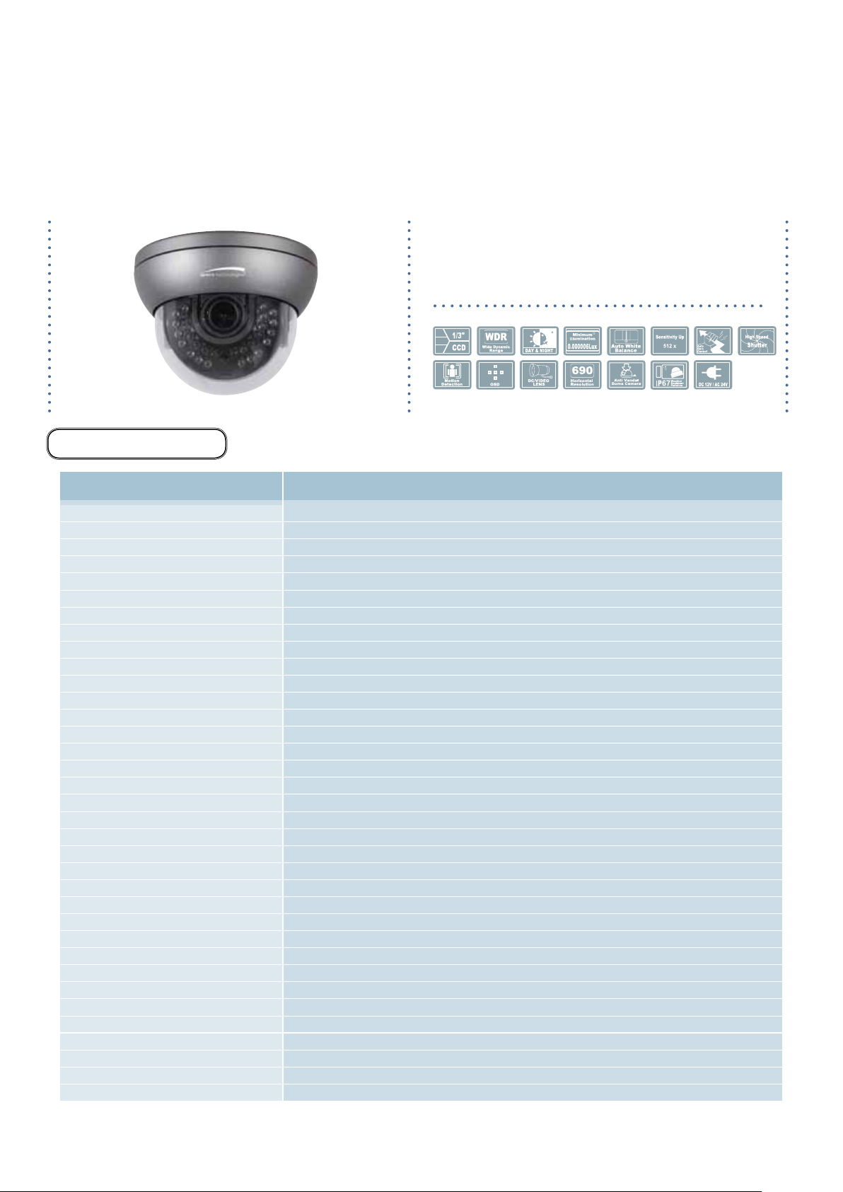
WDRD10H
(Outdoor IR Dome Camera)
WDRD20H
(Indoor IR Dome Camera)
WDRB11H
(Outdoor Bullet Camera with mount plate)
WDRD11H
(Outdoor Dome Camera)
WDRD21H
(Indoor Wall & Ceiling Mount Dome Camera)
WDRD21HW
(Indoor Wall & Ceiling Mount Dome Camera)
Speco Technologies is constantly developing product improvements.
We reserve the right to modify product design and specifications without notice and without incurring any obligation. Rev. 12/01/2013
Page 2

Precautions
◑
Contents ...................................................... 1
◑
Precautions ................................................. 2, 3
◑
Safety Instructions ...................................... 4
◑
Package Contents ....................................... 5
◑
Camera Installation ..................................... 6-15
◑
Specications .............................................. 16-21
◑
Camera Dimension ..................................... 22-24
◑
Features ...................................................... 25
◑
OSD Menu Details ...................................... 26-56
◑
Trouble Shooting ......................................... 57
- 1 -
Page 3
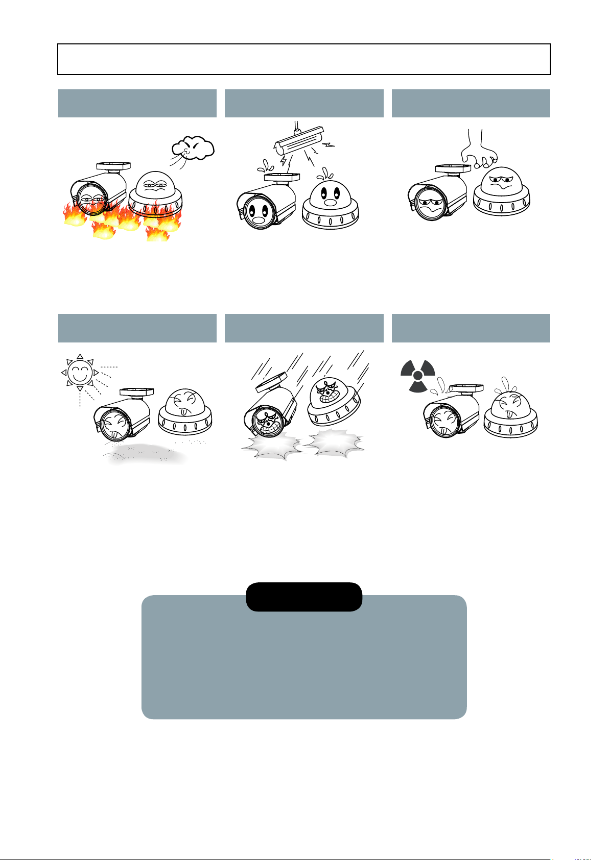
Precautions
Do not install the camera in
extreme temperature conditions.
Only use the camera under conditions
where temperatures are between
-10°C and +50°C. Be especially careful to
provide ventilation when operating under
high temperatures.
Never keep the camera pointed
directly at strong light.
Do not install the camera under
unstable lighting conditions.
Severe lighting change or flicker can
cause the camera to work improperly.
Do not drop the camera or subject
it to physical shocks.
Do not touch the front lens of the
camera.
This is one of the most important parts of
the camera. Be careful not to leave
fingerprints on the lens cover.
Do not expose the camera to
radioactivity.
It can cause malfunctions to occur. If exposed to radioactivity the CCD
Housing damage can compromise
weatherproof ratings.
will fail.
NOTE
* If the camera is exposed to spotlight or object reflecting strong light,
smear or blooming may occur.
* please check that the power satisfies the normal specification before
connecting the camera.
- 2 -
Page 4
CAUTION
CAUTION
RISK OF ELECTRIC SHOCK
DO NOT OPEN
CAUTION:TO REDUCE THE RISK OF ELECTRIC SHOCK
DO NOT REMOVE COVER(OR BACK).
NO USER-SERVICEABLE PARTS INSIDE.
REFER SERVICING TO QUALIFIED SERVICE PERSONNEL.
ISO14001
CAUTION
RISK OF ELECTRIC SHOCK
DO NOT OPEN
CAUTION:TO REDUCE THE RISK OF ELECTRIC SHOCK
DO NOT REMOVE COVER(OR BACK).
NO USER-SERVICEABLE PARTS INSIDE.
REFER SERVICING TO QUALIFIED SERVICE PERSONNEL.
ISO14001
RISK OF ELECTRIC SHOCK
DO NOT OPEN
CAUTION:TO REDUCE THE RISK OF ELECTRIC SHOCK
DO NOT REMOVE COVER(OR BACK).
NO USER-SERVICEABLE PARTS INSIDE.
REFER SERVICING TO QUALIFIED SERVICE PERSONNEL.
ISO14001
The lightning flash with an arrowhead symbol, within an equilateral
triangle is intended to alert the user to the presence of uninsulated
dangerous voltage within the product's enclosure that may be of
sufficient magnitude to constitute a risk of electric shock to persons.
The exclamation point within an equilateral triangle is intended to alert
the user to the presence of important operating and maintenance
(servicing) instructions in the literature accompanying the appliance.
In USA and Canada, Use Class 2 Power Supply Only
INFORMATION - This equipment has been tested and found to comply with
limits for a Class A digital device, pursuant to part 15 of the FCC Rules & CE Rules.
These limits are designed to provide reasonable protection against harmful
interference when the equipment is operated in a commercial environment.
This equipment generates, uses, and can radiate radio frequency energy and, if
not installed and used in accordance with the instruction manual, may cause
harmful interference to radio communications.
Operation of this equipment in a residential area is likely to cause harmful
interference in which case the user will be required to correct the interference at
their own expense.
WARNING - Changes or modifications not expressly approved by the
manufacturer could void the user’s authority to operate the equipment.
CAUTION : To prevent electric shock and risk of fire hazards:
☞Do NOT use power sources other than those specified.
- 3 -
Page 5

Safety Instructions
Precautions for use
◑
This camera should be installed by qualied personnel only
◑
There are no user serviceable parts inside
◑
Do not disassemble this camera other than to make initial adjustments
◑
Use a UL approved regulated 24 volt AC or 12 volt DC power supply
◑
Use appropriate low voltage power cable to prevent re or electrical shock
◑
Please insure that your installation area can support the weight of the camera
Please handle this camera carefully :
◑
Do not use a strong or abrasive detergent when cleaning the camera
◑
Do not install near cooling or heating device
- 4 -
Page 6

Package Contents
Please make sure that the following items are included in the Package:
1) WDRB10H
• 1 Video Test Connector, Power Jack
• 1 Focus Adjustment
• 1 Bracket Base
• 1 Wrench
• Set Screw
- 4 Tapping Screws 4x25
- 4 Hexagon Socket Screws M5x10
2) WDRD10H
• 1 Video Test Connector, Power Jack
• 1 Chameleon Cover
• 1 Wrench
• Set Screw
- 3 Tapping Screws 4x40
- 1 Hexagon Socket Screw M4x8
3) WDRD20H
• 1 Video Test Connector, Power Jack
• 1 Chameleon Cover
• Set Screw
- 3 Tapping Screws 4x25
4) WDRB11H
• 1 Video Test Connector, Power Jack
• 1 Bracket Base
• 2 Wrenches
• Set Screw
- 4 Tapping Screws 4x25
- 4 Hexagon Socket Screws 5x10
5) WDRD11H
• 1 Video Test Connector, Power Jack
• 1 Chameleon Cover
• 1 Wrench
• Set Screw
- 3 Tapping Screws 4x40
- 1 Hexagon Socket Screw M4x8
6) WDRD21H
• 1 Video Test Connector, Power Jack
• 2 Screws
- 2 Tapping Screws 4x20
7) WDRD21HW
• 1 Video Test Connector, Power Jack
• 2 Screws
- 2 Tapping Screws 4x20
- 5 -
Page 7
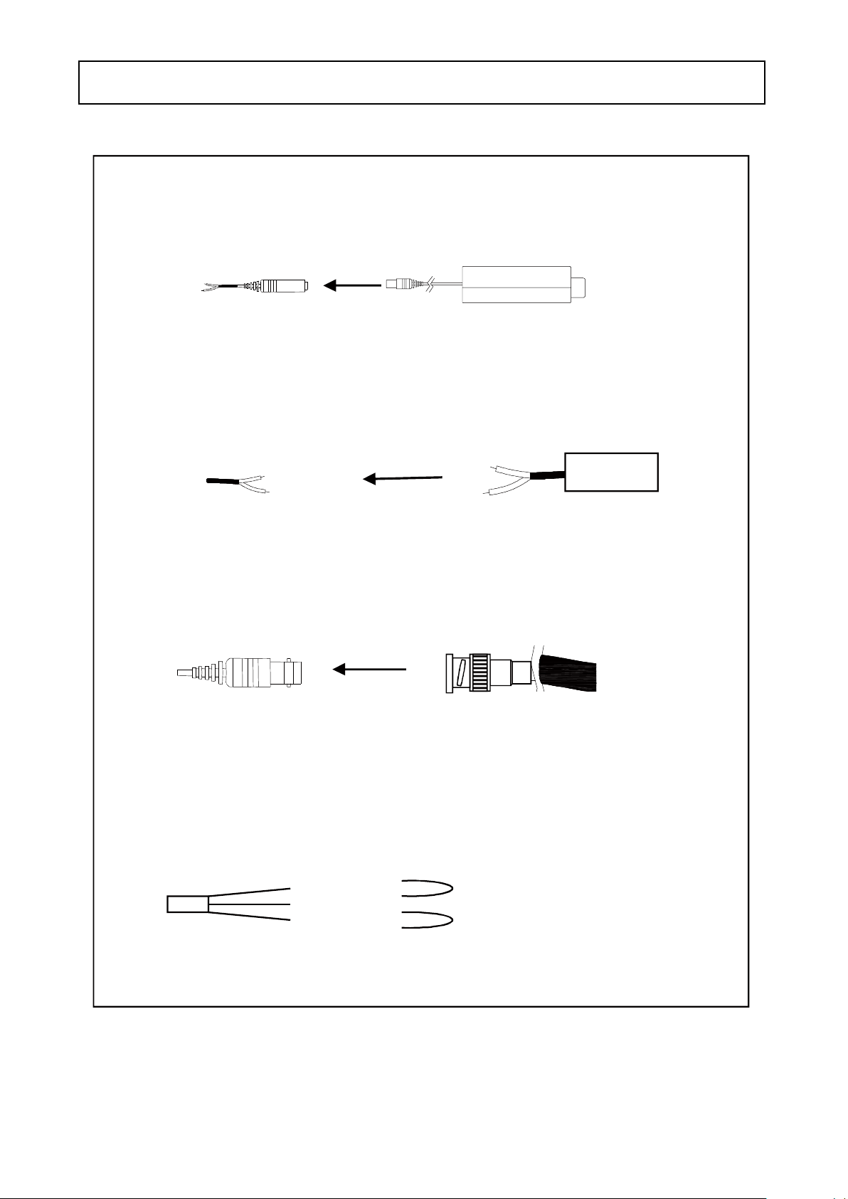
CAMERA INSTALLATION
jvuulj{Gwv~lyGjhislG
XUG~oluG|zpunGXYG}vs{zGkjGOGG\WWGhPG
YUG~oluG|zpunGY[G}vs{zGhjGO[WG}GhP
ZUGjvuulj{G}pklvGjhislG
Tjvuulj{GiujGjhislG{vG{olGiujGqhjrUG
[UGjvuulj{GhGGOyGP
TjGORGSGjvtPGGwGGGOTUGjvtPGG
uGGGlGhGkGGtG
kGG˄vu˅GGGU
kjGXY}GwGz
wGpGaylk
jGaGORP
ishjraOTP
ylkORP
wGz
hjGY[}
R
T
jvtG
hGvG
wGhGkG
uGhGk
- 6 -
Page 8
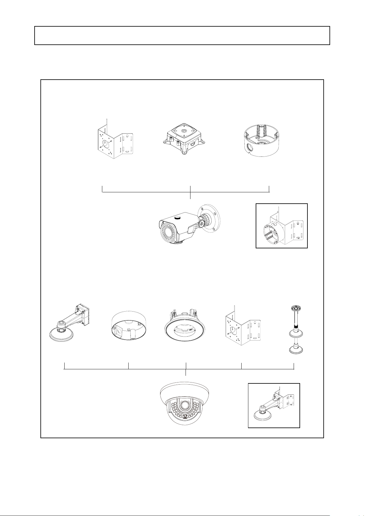
Compatibility
1) WDRB10H
CAMERA INSTALLATION
INTCM INTJBS CVCJBB
2) WDRD10H / WDRD20H
CVCJBD INTPMDFM INTCMINTWM
- 7 -
Page 9
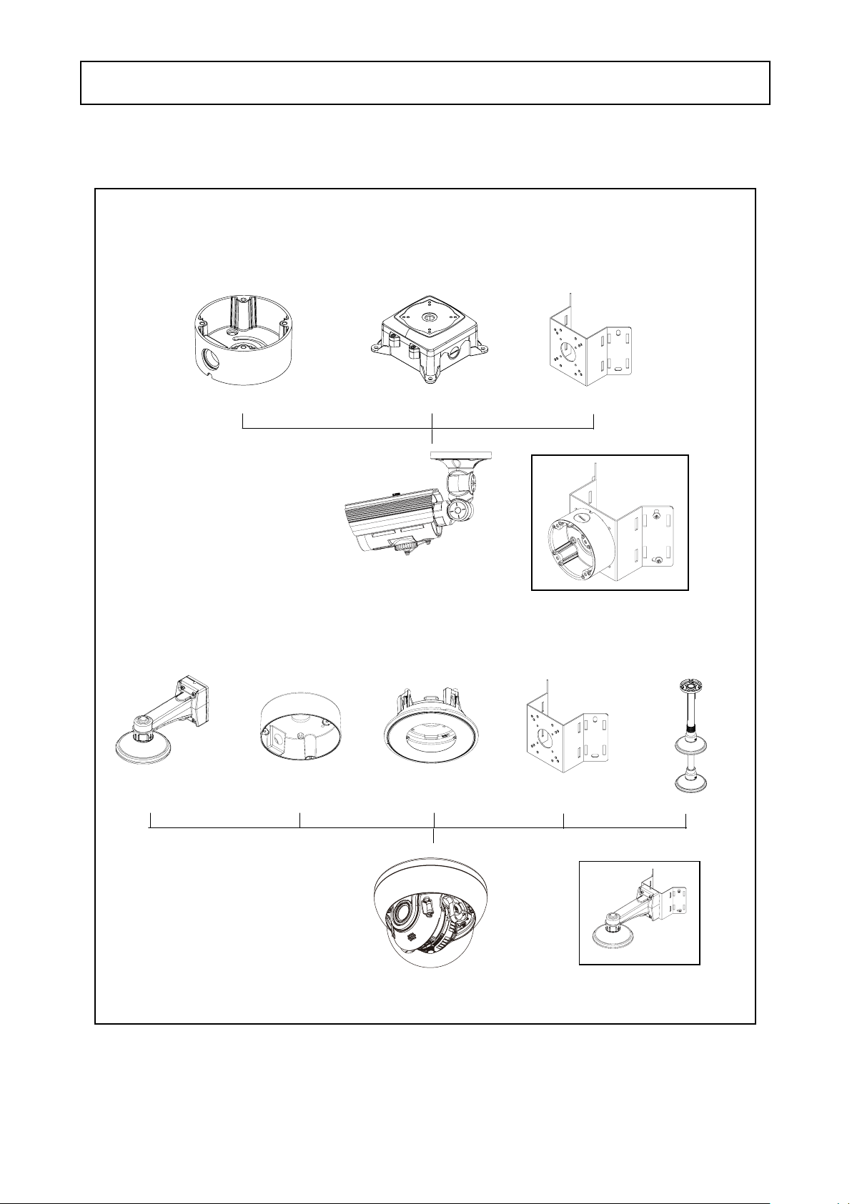
Compatibility
3) WDRB11H
CAMERA INSTALLATION
CVCJBB INTJBS INTCM
4) WDRD11H
CVCJBD INTPMDFM INTCMINTWM
- 8 -
Page 10
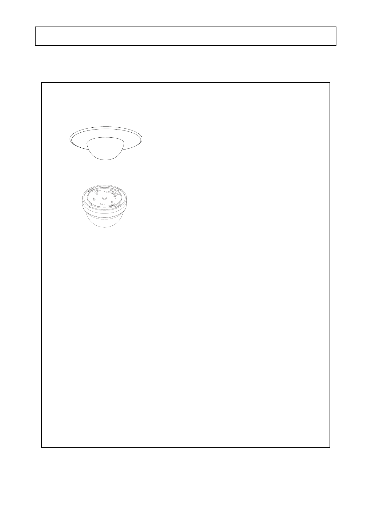
Compatibility
5) WDRD21H / WDRD21HW
DFM
CAMERA INSTALLATION
- 9 -
Page 11
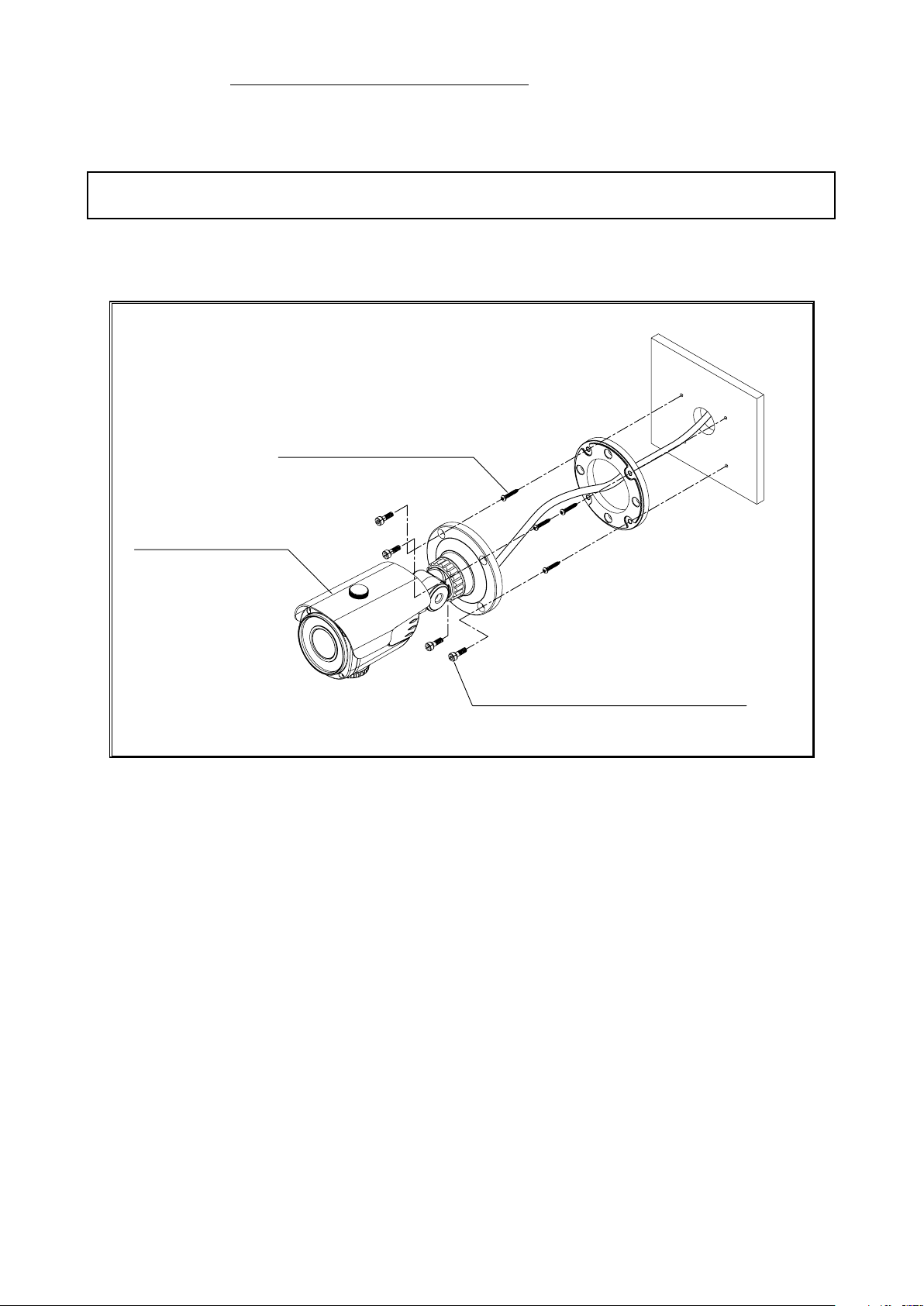
TAPPING SCREW 4X25, 4EA
HEXAGON SOCKET SCREW M5X10, 4EA
CAMERA ASSEMBLY
CAUTION : The installation instructions in this manual are for use by qualified service
personnel only. To reduce the risk of electric shock, do not perform any servicing other
than that contained in the operating instructions unless you are qualified to do so.
1. WDRB10H
CAMERA INSTALLATION
- 10 -
Page 12
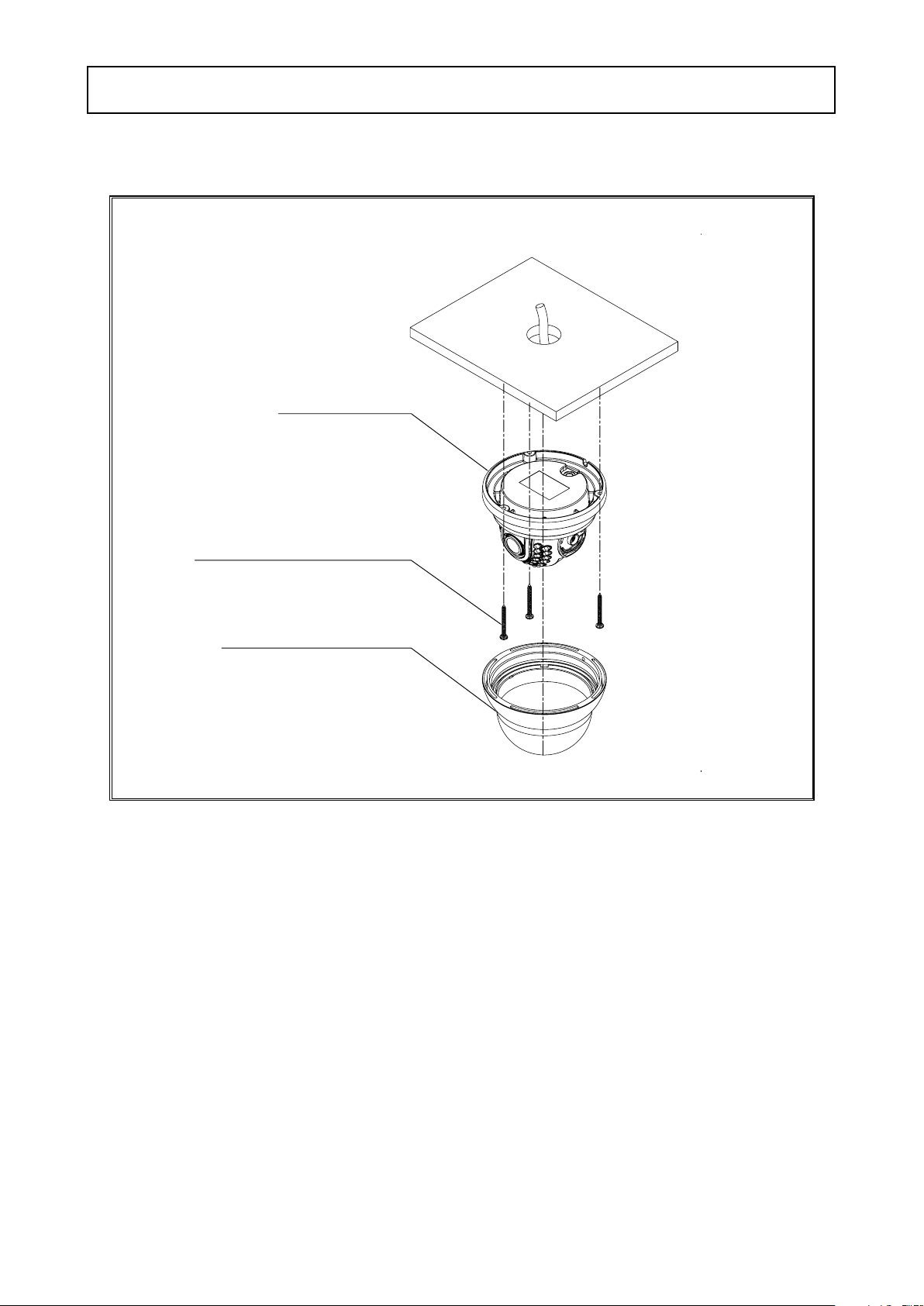
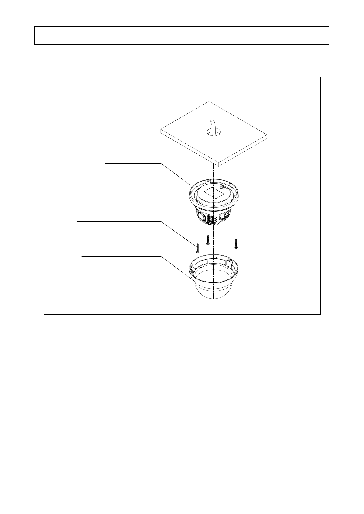
2. WDRD10H
BASE ASSEMBLY
TAPPING SCREW 4X25, 3EA
DOME COVER ASSEMBLY
CAMERA INSTALLATION
- 11 -
Page 13
3. WDRD20H
TAPPING SCREW 4X25, 3EA
DOME COVER ASSEMBLY
BASE ASSEMBLY
CAMERA INSTALLATION
- 12 -
Page 14
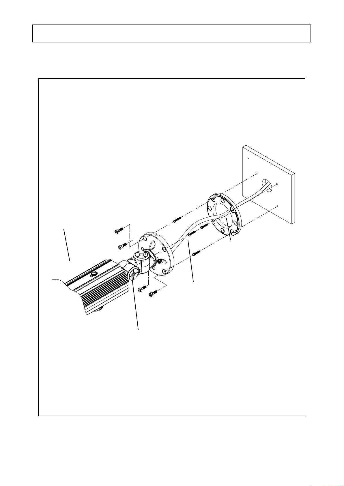
4. WDRB11H
CAMERA INSTALLATION
CAMERA ASSEMBLY
BASE ADAPTOR BRACKET
TAPPING SCREW 4X25, 4EA
HEXAGON SOCKET SCREW M5X10, 4EA
- 13 -
Page 15
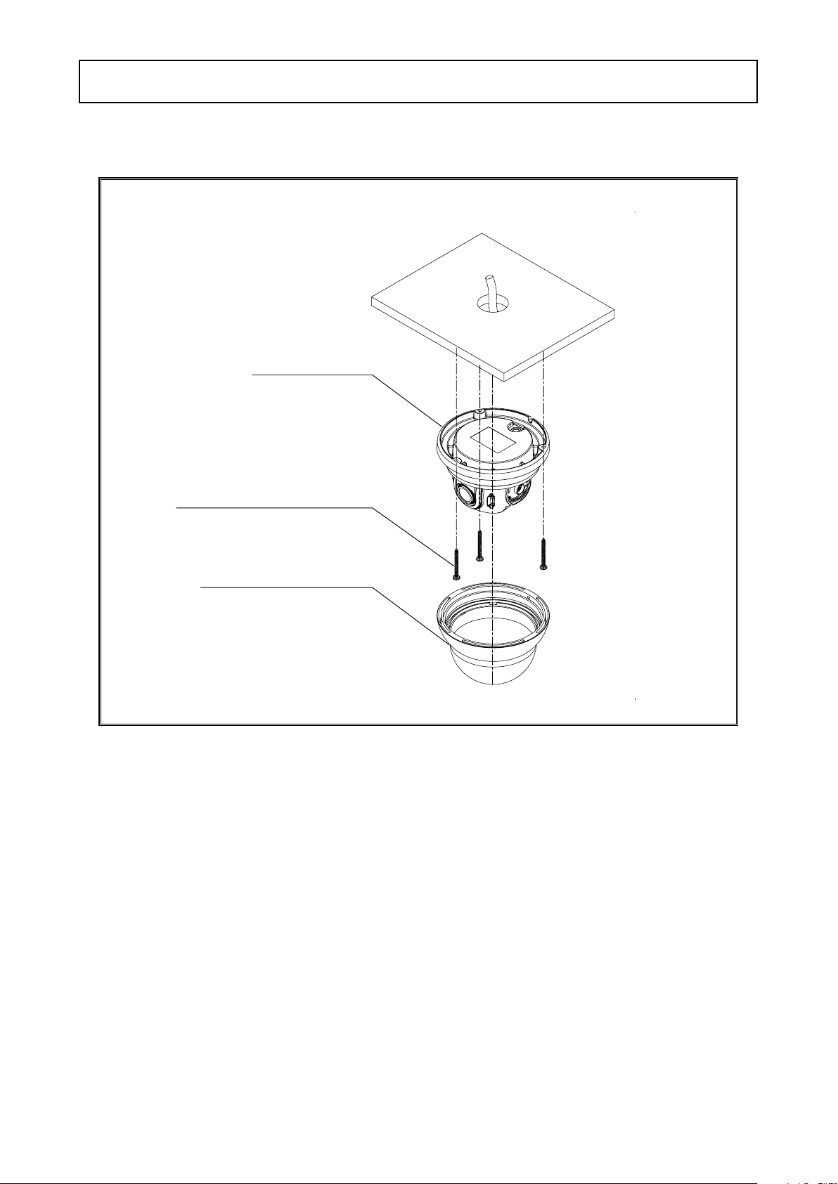
5. WDRD11H
BASE ASSEMBLY
TAPPING SCREW 4X25, 3EA
DOME COVER ASSEMBLY
CAMERA INSTALLATION
- 14 -
Page 16
CAMERA INSTALLATION
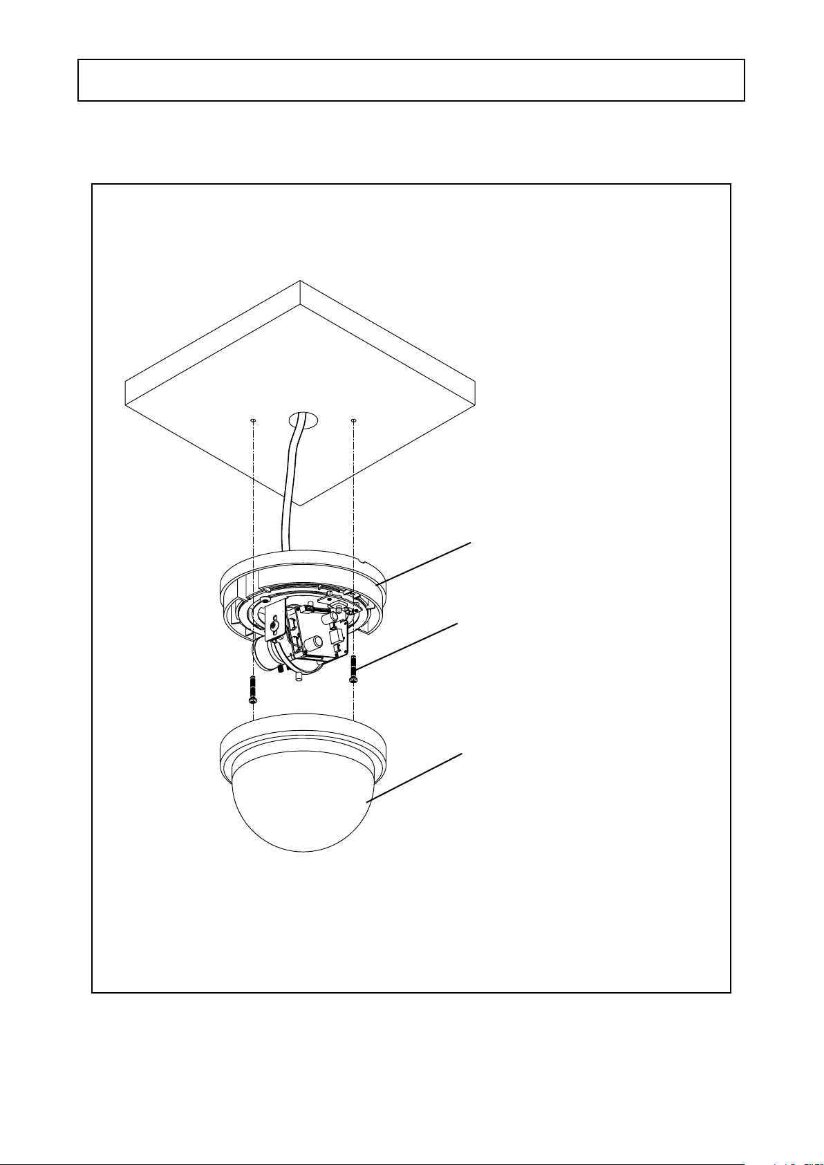
6. WDRD21H / WDRD21HW
BASE ASSEMBLY
TAPPING SCREW 4X20, 2EA
DOME COVER ASSEMBLY
- 15 -
Page 17
Speco Technologies
(Outdoor IR Bullet Camera)
DC Auto Iris Varifocal Lens 2.8-12mm
SPECIFICATIONS
WDRB10H
■
MODEL
Image Sensor
TV System
Total Pixels
Effective Pixels
Scanning System
Synchronization
O.S.D
BLC / HLC
Horizontal Resolution
S/N (Y Signal)
Minimum Illumination
White Balance
Electronic Shutter Speed
Slow Shutter (Sense-Up)
Gain Control
2D.3DNR
WDR
Motion Detection
Privacy
Mirror
Sharpness
Day/Night switch
IR OPT (SMART- IR, ATR WD-EX)
Digital E-ZOOM
DIS
DEFECT ADJ
Communication
Language
Power
Power Consumption
Lens
Storage Temperature
Operating Temperature
Dimension
Weight
WDRB10H
1/3'' SONY HAD CCD 960H (DUAL SCAN)
NTSC
1,028(H) x 508(V)
976(H) x 494(V)
2:1 Interlace
Internal
Available
ON/OFF
700 TV Lines
52dB (AGC off, Weight on)
0.000006LUX(IR LED ON)
ATW(1,800K ~ 10,500K) / PUSH / USER1 / USER2 / ANTI CR / MANUAL / PUSH LOCK
AUTO / (1/60SEC~ 1/100,000SEC)
AUTO(x2~ x512)
Level Adjustable (MAX 42dB)
OFF, LOW, MIDLOW, MID, MIDHIGH, HIGH (2D+3D)
OFF / ON (CONTRAST: LOW, MIDLOW, MID, MIDHIGH, HIGH)
ON/OFF (4 Zone)
ON/OFF (15 Zone)
OFF , V-FLIP, H-FLIP, HV-FLIP
0 ~15 Level Adjustable
COLOR, AUTO_(EXT ON/OFF)
SMART- IR(AUTO, CENTER Adjustable) , ATR WD-EX ON/OFF
0 ~ 255 Level Adjustable (x1 ~ x16) PAN / TILT
ON/OFF
Auto: 64 Points
Coaxial
ENGLISH,JAPANESE,DEUTSCH,FRENCH, RUSSIAN, PORTUGUESE, SPANISH
Dual Voltage
IR LED ON:700mA Max
DC Auto Iris Varifocal Lens (2.8-12mm)
-4ºF ~ 140ºF RH 95% Max
-4ºF ~ 140ºF RH 95% Max
3.94"(W) * 3.94"(H) * 8.27"(D)
3.09 Ibs
- 16 -
Page 18
Speco Technologies
(Outdoor IR Dome Camera)
DC Auto Iris Varifocal Lens 2.8-12mm
SPECIFICATIONS
WDRD10H
■
MODEL
Image Sensor
TV System
Total Pixels
Effective Pixels
Scanning System
Synchronization
O.S.D
BLC / HLC
Horizontal Resolution
S/N (Y Signal)
Minimum Illumination
White Balance
Electronic Shutter Speed
Slow Shutter (Sense-Up)
Gain Control
2D.3DNR
WDR
Motion Detection
Privacy
Mirror
Sharpness
Day/Night switch
IR OPT (SMART- IR, ATR WD-EX)
Digital E-ZOOM
DIS
DEFECT ADJ
Communication
Language
Power
Power Consumption
Lens
Storage Temperature
Operating Temperature
Dimension
Weight
WDRD10H
1/3'' SONY HAD CCD 960H (DUAL SCAN)
NTSC
1,028(H) x 508(V)
976(H) x 494(V)
2:1 Interlace
Internal
Available
ON/OFF
700 TV Lines
52dB (AGC off, Weight on)
0.000006LUX(IR LED ON)
ATW(1,800K ~ 10,500K) / PUSH / USER1 / USER2 / ANTI CR / MANUAL / PUSH LOCK
AUTO / (1/60SEC~ 1/100,000SEC)
AUTO(x2~ x512)
Level Adjustable (MAX 42dB)
OFF, LOW, MIDLOW, MID, MIDHIGH, HIGH (2D+3D)
OFF / ON (CONTRAST: LOW, MIDLOW, MID, MIDHIGH, HIGH)
ON/OFF (4 Zone)
ON/OFF (15 Zone)
OFF , V-FLIP, H-FLIP, HV-FLIP
0 ~15 Level Adjustable
COLOR, AUTO_(EXT ON/OFF)
SMART- IR(AUTO, CENTER Adjustable) , ATR WD-EX ON/OFF
0 ~ 255 Level Adjustable (x1 ~ x16) PAN / TILT
ON/OFF
Auto: 64 Points
Coaxial
ENGLISH,JAPANESE,DEUTSCH,FRENCH, RUSSIAN, PORTUGUESE, SPANISH
Dual Voltage
IR LED ON:500mA Max
DC Auto Iris Varifocal Lens (2.8-12mm)
-4ºF ~ 140ºF RH 95% Max
-4ºF ~ 140ºF RH 95% Max
5.12"(Dia) * 3.94"(H)
1.98 Ibs
- 17 -
Page 19

Speco Technologies
(Indoor IR Dome Camera)
DC Auto Iris Varifocal Lens 2.8-12mm
SPECIFICATIONS
WDRD20H
■
MODEL
Image Sensor
TV System
Total Pixels
Effective Pixels
Scanning System
Synchronization
O.S.D
BLC / HLC
Horizontal Resolution
S/N (Y Signal)
Minimum Illumination
White Balance
Electronic Shutter Speed
Slow Shutter (Sense-Up)
Gain Control
2D.3DNR
WDR
Motion Detection
Privacy
Mirror
Sharpness
Day/Night switch
IR OPT (SMART- IR, ATR WD-EX)
Digital E-ZOOM
DIS
DEFECT ADJ
Communication
Language
Power
Power Consumption
Lens
Storage Temperature
Operating Temperature
Dimension
Weight
WDRD20H
1/3'' SONY HAD CCD 960H (DUAL SCAN)
NTSC
1,028(H) x 508(V)
976(H) x 494(V)
2:1 Interlace
Internal
Available
ON/OFF
700 TV Lines
52dB (AGC off, Weight on)
0.000006LUX(IR LED ON)
ATW(1,800K ~ 10,500K) / PUSH / USER1 / USER2 / ANTI CR / MANUAL / PUSH LOCK
AUTO / (1/60SEC~ 1/100,000SEC)
AUTO(x2~ x512)
Level Adjustable (MAX 42dB)
OFF, LOW, MIDLOW, MID, MIDHIGH, HIGH (2D+3D)
OFF / ON (CONTRAST: LOW, MIDLOW, MID, MIDHIGH, HIGH)
ON/OFF (4 Zone)
ON/OFF (15 Zone)
OFF , V-FLIP, H-FLIP, HV-FLIP
0 ~15 Level Adjustable
COLOR, AUTO_(EXT ON/OFF)
SMART- IR(AUTO, CENTER Adjustable) , ATR WD-EX ON/OFF
0 ~ 255 Level Adjustable (x1 ~ x16) PAN / TILT
ON/OFF
Auto: 64 Points
Coaxial
ENGLISH,JAPANESE,DEUTSCH,FRENCH, RUSSIAN, PORTUGUESE, SPANISH
Dual Voltage
IR LED ON:500mA Max
DC Auto Iris Varifocal Lens (2.8-12mm)
-4ºF ~ 140ºF RH 95% Max
-4ºF ~ 140ºF RH 95% Max
5.12"(Dia) * 3.94"(H)
1.32 Ibs
- 18 -
Page 20

Speco Technologies
(Weatherproof Bullet Camera with mount plate)
DC Auto Iris Varifocal Lens 2.8-12mm
WDRB11H
■
SPECIFICATIONS
MODEL
Image Sensor
TV System
Total Pixels
Effective Pixels
Scanning System
Synchronization
O.S.D
BLC / HLC
Horizontal Resolution
S/N (Y Signal)
Minimum Illumination
White Balance
Electronic Shutter Speed
Slow Shutter (Sense-Up)
Gain Control
2D.3DNR
WDR
Motion Detection
Privacy
Mirror
Sharpness
Day/Night switch
IR OPT (SMART- IR, ATR WD-EX)
Digital E-ZOOM
DIS
DEFECT ADJ
Communication
Language
Power
Power Consumption
Lens
Storage Temperature
Operating Temperature
Dimension
Weight
WDRB11H
1/3'' SONY HAD CCD 960H (DUAL SCAN)
NTSC
1,028(H) x 508(V)
976(H) x 494(V)
2:1 Interlace
Internal
Available
ON/OFF
700 TV Lines
52dB (AGC off, Weight on)
0.000006LUX
ATW(1,800K ~ 10,500K) / PUSH / USER1 / USER2 / ANTI CR / MANUAL / PUSH LOCK
AUTO / (1/60SEC~ 1/100,000SEC)
AUTO(x2~ x512)
Level Adjustable (MAX 42dB)
OFF, LOW, MIDLOW, MID, MIDHIGH, HIGH (2D+3D)
OFF / ON (CONTRAST: LOW, MIDLOW, MID, MIDHIGH, HIGH)
ON/OFF (4 Zone)
ON/OFF (15 Zone)
OFF , V-FLIP, H-FLIP, HV-FLIP
0 ~15 Level Adjustable
COLOR, AUTO_(EXT ON/OFF)
SMART- IR(AUTO, CENTER Adjustable) , ATR WD-EX ON/OFF
0 ~ 255 Level Adjustable (x1 ~ x16) PAN / TILT
ON/OFF
Auto: 64 Points
Coaxial
ENGLISH,JAPANESE,DEUTSCH,FRENCH, RUSSIAN, PORTUGUESE, SPANISH
Dual Voltage
DC 12V 400mA / AC24V 170mA
DC Auto Iris Varifocal Lens (2.8-12mm)
-4ºF ~ 140ºF RH 95% Max
-4ºF ~ 140ºF RH 95% Max
3.46"(W) * 4.01"(H) * 11.02"(D)
3 lbs
- 19 -
Page 21

Speco Technologies
(Weatherproof Dome Camera with Chameleon™ Cover)
DC Auto Iris Varifocal Lens 2.8-12mm
WDRD11H
■
SPECIFICATIONS
MODEL
Image Sensor
TV System
Total Pixels
Effective Pixels
Scanning System
Synchronization
O.S.D
BLC / HLC
Horizontal Resolution
S/N (Y Signal)
Minimum Illumination
White Balance
Electronic Shutter Speed
Slow Shutter (Sense-Up)
Gain Control
2D.3DNR
WDR
Motion Detection
Privacy
Mirror
Sharpness
Day/Night switch
IR OPT (SMART- IR, ATR WD-EX)
Digital E-ZOOM
DIS
DEFECT ADJ
Communication
Language
Power
Power Consumption
Lens
Storage Temperature
Operating Temperature
Dimension
Weight
WDRD11H
1/3'' SONY HAD CCD 960H (DUAL SCAN)
NTSC
1,028(H) x 508(V)
976(H) x 494(V)
2:1 Interlace
Internal
Available
ON/OFF
700 TV Lines
52dB (AGC off, Weight on)
0.000006LUX
ATW(1,800K ~ 10,500K) / PUSH / USER1 / USER2 / ANTI CR / MANUAL / PUSH LOCK
AUTO / (1/60SEC~ 1/100,000SEC)
AUTO(x2~ x512)
Level Adjustable (MAX 42dB)
OFF, LOW, MIDLOW, MID, MIDHIGH, HIGH (2D+3D)
OFF / ON (CONTRAST: LOW, MIDLOW, MID, MIDHIGH, HIGH)
ON/OFF (4 Zone)
ON/OFF (15 Zone)
OFF , V-FLIP, H-FLIP, HV-FLIP
0 ~15 Level Adjustable
COLOR, AUTO_(EXT ON/OFF)
SMART- IR(AUTO, CENTER Adjustable) , ATR WD-EX ON/OFF
0 ~ 255 Level Adjustable (x1 ~ x16) PAN / TILT
ON/OFF
Auto: 64 Points
Coaxial
ENGLISH,JAPANESE,DEUTSCH,FRENCH, RUSSIAN, PORTUGUESE, SPANISH
Dual Voltage
DC 12V 400mA / AC24V 170mA
DC Auto Iris Varifocal Lens (2.8-12mm)
-4ºF ~ 140ºF RH 95% Max
-4ºF ~ 140ºF RH 95% Max
5.12"(Dia) * 3.94"(H)
1.98 lbs
- 20 -
Page 22

Speco Technologies
(Indoor Wall & Ceiling Mount Dome Camera)
DC Auto Iris Varifocal Lens 2.8-12mm
WDRD21H
■
SPECIFICATIONS
MODEL
Image Sensor
TV System
Total Pixels
Effective Pixels
Scanning System
Synchronization
O.S.D
BLC / HLC
Horizontal Resolution
S/N (Y Signal)
Minimum Illumination
White Balance
Electronic Shutter Speed
Slow Shutter (Sense-Up)
Gain Control
2D.3DNR
WDR
Motion Detection
Privacy
Mirror
Sharpness
Day/Night switch
IR OPT (SMART- IR, ATR WD-EX)
Digital E-ZOOM
DIS
DEFECT ADJ
Communication
Language
Power
Power Consumption
Lens
Storage Temperature
Operating Temperature
Dimension
Weight
WDRD21H
1/3'' SONY HAD CCD 960H (DUAL SCAN)
NTSC
1,028(H) x 508(V)
976(H) x 494(V)
2:1 Interlace
Internal
Available
ON/OFF
700 TV Lines
52dB (AGC off, Weight on)
0.000006LUX
ATW(1,800K ~ 10,500K) / PUSH / USER1 / USER2 / ANTI CR / MANUAL / PUSH LOCK
AUTO / (1/60SEC~ 1/100,000SEC)
AUTO(x2~ x512)
Level Adjustable (MAX 42dB)
OFF, LOW, MIDLOW, MID, MIDHIGH, HIGH (2D+3D)
OFF / ON (CONTRAST: LOW, MIDLOW, MID, MIDHIGH, HIGH)
ON/OFF (4 Zone)
ON/OFF (15 Zone)
OFF , V-FLIP, H-FLIP, HV-FLIP
0 ~15 Level Adjustable
COLOR, AUTO_(EXT ON/OFF)
SMART- IR(AUTO, CENTER Adjustable) , ATR WD-EX ON/OFF
0 ~ 255 Level Adjustable (x1 ~ x16) PAN / TILT
ON/OFF
Auto: 64 Points
Coaxial
ENGLISH,JAPANESE,DEUTSCH,FRENCH, RUSSIAN, PORTUGUESE, SPANISH
Dual Voltage
DC 12V 250mA
DC Auto Iris Varifocal Lens (2.8-12mm)
-4ºF ~ 140ºF RH 95% Max
-4ºF ~ 140ºF RH 95% Max
5.51"(Dia) * 4.09"(H)
1.54 lbs
- 21 -
Page 23

Speco Technologies
(Indoor Wall & Ceiling Mount Dome Camera)
DC Auto Iris Varifocal Lens 2.8-12mm
WDRD21HW
■
SPECIFICATIONS
MODEL
Image Sensor
TV System
Total Pixels
Effective Pixels
Scanning System
Synchronization
O.S.D
BLC / HLC
Horizontal Resolution
S/N (Y Signal)
Minimum Illumination
White Balance
Electronic Shutter Speed
Slow Shutter (Sense-Up)
Gain Control
2D.3DNR
WDR
Motion Detection
Privacy
Mirror
Sharpness
Day/Night switch
IR OPT (SMART- IR, ATR WD-EX)
Digital E-ZOOM
DIS
DEFECT ADJ
Communication
Language
Power
Power Consumption
Lens
Storage Temperature
Operating Temperature
Dimension
Weight
WDRD21HW
1/3'' SONY HAD CCD 960H (DUAL SCAN)
NTSC
1,028(H) x 508(V)
976(H) x 494(V)
2:1 Interlace
Internal
Available
ON/OFF
700 TV Lines
52dB (AGC off, Weight on)
0.000006LUX
ATW(1,800K ~ 10,500K) / PUSH / USER1 / USER2 / ANTI CR / MANUAL / PUSH LOCK
AUTO / (1/60SEC~ 1/100,000SEC)
AUTO(x2~ x512)
Level Adjustable (MAX 42dB)
OFF, LOW, MIDLOW, MID, MIDHIGH, HIGH (2D+3D)
OFF / ON (CONTRAST: LOW, MIDLOW, MID, MIDHIGH, HIGH)
ON/OFF (4 Zone)
ON/OFF (15 Zone)
OFF , V-FLIP, H-FLIP, HV-FLIP
0 ~15 Level Adjustable
COLOR, AUTO_(EXT ON/OFF)
SMART- IR(AUTO, CENTER Adjustable) , ATR WD-EX ON/OFF
0 ~ 255 Level Adjustable (x1 ~ x16) PAN / TILT
ON/OFF
Auto: 64 Points
Coaxial
ENGLISH,JAPANESE,DEUTSCH,FRENCH, RUSSIAN, PORTUGUESE, SPANISH
Dual Voltage
DC 12V 250mA
DC Auto Iris Varifocal Lens (2.8-12mm)
-4ºF ~ 140ºF RH 95% Max
-4ºF ~ 140ºF RH 95% Max
5.51"(Dia) * 4.09"(H)
1.54 lbs
- 22 -
Page 24

1) WDRB10H
3.94”dia
CAMERA DIMENSION
8.27”
4.72”
3.94”dia
2) WDRD10H
3.94”dia
4.49”
5.12”dia
1.61”
5.12”dia
- 23 -
Page 25

3) WDRD20H
CAMERA DIMENSION
3.94”dia
4) WDRB11H
3.46”
5.12”dia
3.94”
1.61”
5.12”dia
11.02”
5.90”
4.01”
3.11”
3.89” dia
5.03”
10.51”
- 24 -
Page 26

5) WDRD11H
CAMERA DIMENSION
3.94”dia
6) WDRD21H / WDRD21HW
5.51” dia
5.12”dia
3.94”
1.61”
5.12”dia
5.51” dia
1.25”
4.60” dia
4.09”
- 25 -
Page 27

FEATURES
2D.3DNR Filtering Method of Newly Advanced DNR Function
Newly developed 2D filtering enhances Digital Noise reduction at low light levels. 2D
Filtering of the Video Signal Optimises the Signal to Noise ratio.
High Resolution
The combination of a Sony Super HAD CCD image sensor and DNR DSP provides an
excellent resolution of 700 TV lines.
Wide Dynamic Range
WDR is a powerful and ultra advanced technology that captures cleaner and superior
high resolution pictures even where the images appear dark because there is a strong
back light present.
High Spotlight BLC Function
Users Can Adjust and Select the Special Required Area to Observe the Target Object
Under the Strong Spots of Light Exist.
Illumination
With an Incredibly minimum illumination of 0.01Lux, the sensor can capture good
images even in extremely low light conditions. Noise is significantly reduced by the
ultra advanced DNR (Digital Noise Reduction) technology.
Additional Functions
OSD - On Screen Display menu with multi-Language support.
Privacy Masking -15 zones, Motion - 4 zones.
- 26 -
Page 28

Menu Set Up (SPECO TECH 1/3)
Menu items can be selected by using the OSD buttons of the camera
1. Press the Set Up button.
* The Set Up menu will be displayed on the monitor.
SPECO TECH 1/3
LENS
SHUTTER/AGC
PICT ADJUST
WHITE BAL
WDR
2D.3DNR
NEXT
EXIT
AUTO
AUTO
ANTI CR
SAVE ALL
2. Move and select the required function using the Up and Down button.
* Move the arrow indicator Up or Down to select the desired feature by pressing
the Up or Down button.
SPECO TECH 1/3
LENS
SHUTTER/AGC
PICT ADJUST
WHITE BAL
WDR
2D.3DNR
NEXT
EXIT
AUTO
AUTO
ANTI CR
SAVE ALL
- 27 -
Page 29

3. Change menu settings using the Left or Right button.
* Available values or Status are displayed by pressing the Left or Right buttons.
Press the button until desired value / status is displayed.
4. After Changing the setting move the arrow indicator to EXIT and press the
SET button to EXIT.
NOTE
* Move to the available submenu by moving arrow to desired feature.
Lens
This function is used to set the mechanical iris of the lens.
1. Move the arrow indicator to Lens using the Up and Down buttons on the Set Up menu screen.
2. Select the mechanical iris type by pressing the left or right button between Manual and Auto.
SPECO TECH 1/3
LENS
SHUTTER/AGC
PICT ADJUST
WHITE BAL
WDR
2D.3DNR
NEXT
EXIT
AUTO
AUTO
ANTI CR
SAVE ALL
- 28 -
Page 30

AUTO IRIS
TYPE
MODE
SPEED
MODE
RETURN
3. Set DC or Video by selecting type on the Auto Iris screen.
4. Press the RETURN to return to the SETUP menu.
DC
AUTO
075
OUTDOOR
Shutter/AGC
This function is used to select Automatic or Manual shutter speed control.
1. On the Set Up menu screen select SHUTTER/AGC by using the Up or Down button.
2. Select the desired shutter mode by pressing the Left or Right button.
SPECO TECH 1/3
LENS
SHUTTER/AGC
PICT ADJUST
WHITE BAL
WDR
2D.3DNR
NEXT
EXIT
AUTO
AUTO
ANTI CR
SAVE ALL
- 29 -
Page 31

AUTO SETUP
HIGH LUMINANCE
MODE
BRIGHTNESS
LOW LUMINANCE
MODE
BRIGHTNESS
RETURN
SHUT+AUTO IRIS
126
AGC->SLOW1
-----
HIGH LUMINANCE
* MODE : Shutter is fixed at 1/60, 1/50 and average brightness maintains
* BRIGHTNESS : Adjust the brightness level 0~255 by pressing the left or the right button.
LOW LUMINANCE
* MODE
- OFF : AGC and SLOW(SENSE-UP) OFF
- AGC : AGC ON and SLOW(SENSE-UP) OFF.
Enter the LOW LUMINANCE SETUP and adjust GAIN level by pressing the left or the right button.
- SLOW(SENS-UP) : SLOW(SENSE-UP) ON and AGC OFF.
Enter the LOW LUMINANCE SETUP and adjust SLOW(SENSE-UP) level by pressing the left or the right
button.
- AGC->SLOW1(SENS-UP) : AGC and SLOW(SENSE-UP) ON.
When over the selected AGC MAX level, SLOW(SENSE-UP) turns on.
- AGC->SLOW2(SENS-UP) : AGC and SLOW(SENSE-UP) ON.
When over the selected AGCMIN level, SLOW(SENSE-UP) turns on.
- SLOW(SENS-UP)->AGC : AGC and SLOW(SENSE-UP) ON.
When over the selected SLOW(SENSE-UP) level, AGC turns on.
* BRIGHTNESS : Adjust the bright level x0.25 , x0.5 , x0.75 , x1.0 by pressing the left or the right button.
* RETURN : Move previous page.
- 30 -
Page 32

NOTE
* AGC (Auto Gain Control)
A higher gain increases brightness but also increases noise.
MANUAL SETUP
MODE
SHUT
AGC
RETURN
SHUT
1/60(S)
6(DB)
* SHUTTER : Adjust the shutter level 1/60, FLK, 1/100, 1/250, 1/500, 1/1000,1/2000, 1/4000, 1/10000 (S)
adjust the red color GAIN by pressing the left or the right button.
* Adjust the AGC level 6, 12, 18, 24, 30, 36, 42, 44.8, (DB) by pressing the left or the right button.
* RETURN : Move previous page.
- 31 -
Page 33

PICT Adjust
Move the cursor to PICT ADJUST press the SET button.
SPECO TECH 1/3
LENS
SHUTTER/AGC
PICT ADJUST
WHITE BAL
WDR
2D.3DNR
NEXT
EXIT
PICT ADJUST
MIRROR
CONTRAST
SHARPNESS
HUE
R-GAIN
B-GAIN
RETURN
AUTO
AUTO
ANTI CR
SAVE ALL
OFF
039
008
050
158
158
* MIRROR : Select Off, Flip Vertical, Flip Horizon, Flip Horizon and Vertical by pressing the left or the right
button.
* CONTRAST : Adjust the contrast level 0~063 by pressing the left or the right button.
* SHARPNESS : Adjust the sharpness level 0~015 by pressing the left or the right button.
* HUE : Adjust the color level 0~100 - RED, GREEN, BLUE, YELLOW, CYAN, MAGENTA
* R-GAIN : Adjust the red color GAIN 0~255 by pressing the left or the right button.
- 32 -
Page 34

* B-GAIN : Adjust the blue color GAIN 0~255 by pressing the left or the right button.
* RETURN : Move previous page.
White Balance
This function is used to set the white balance operation mode.
1. Move the arrow indicator to WHITE BAL on the SETUP menu screen using the Up and Down button.
2. Select the desired mode by using the Left or Right button.
SPECO TECH 1/3
LENS
SHUTTER/AGC
PICT ADJUST
WHITE BAL
WDR
2D.3DNR
NEXT
EXIT
ATW SETUP
SPEED
DELAY CNT
ATW FRAME
AUTO
AUTO
ANTI CR
SAVE ALL
005
005
x1.5
ENVIRONMENT
RETURN
INDOOR
- 33 -
Page 35

* ATW : Auto tracking white, normal environment setting under fluorescent lamp or outdoors.
- SPEED : Select the start point of auto tracking speed and time by pressing the left or the right button.
- DELAY CNT : Select the start point of Auto tracking speed and time by pressing the left or the right button.
- ATW FRAME : Set up the frame megnification by pressing the left or the right button.
- ENVIRONMENT : It improves color temperature chase accuracy in accordance with environmental set-up.
Select the environment by pressing the left or the right button.
- RETURN : Select return to save the changes in the ATW menu and return to the SETUP menu.
* PUSH : Regardless of subject condition, adjust white balance. Always control locking mode with full-in
frame, white color as set point.
* USER1 WB: The gain values for the outdoor fixed mode are used as the adjustment items of USER1 on the
internal OSD menu.
* USER2 WB: The gain values for the fluorescent light fixed mode are used as the adjustment items of
USER2 on the internal OSD menu.
* ANTI CR : COLOR rolling control
* MANUAL WB: The B and R gain values for manual WB are set on this screen.
- LEVEL UP : Induce change to high color temperature side.
- LEVEL DOWN : Induce change to low color temperature side.
* PRESET : Reset the adjusted color temperature side.
* PUSH LOCK : To get the most suitable status at current lighting environment, push the SET button while
camera focuses on a white plain paper.
- 34 -
Page 36

WDR(Wide Dynamic Range)
* WDR : The wide dynamic range (WDR) function of a camera is intended to provide clear images even
under back light circumstances where intensity of illumination can vary excessively, namely when there are
both very bright and very dark areas simultaneously in the field of view of the camera.
SPECO TECH 1/3
LENS
SHUTTER/AGC
PICT ADJUST
WHITE BAL
WDR
2D.3DNR
NEXT
EXIT
WDR SETUP
MODE
CONTRAST
RETURN
AUTO
AUTO
ANTI CR
SAVE ALL
ON
MIDHIGH
* MODE : Adjust WDR function ON or OFF.
* CONTRAST : Increase bright illuminance and dark illuminance level over average value and then control
the contrast. Select the LOW, MIDLOW, MID, MIDHIGH, HIGH by pressing the left or the right button.
* RETURN : Move previous page.
- 35 -
Page 37

WDR OFF WDR ON
2D.3DNR
2DNR function does Y,C filtering and decrease noise.
The level of 3DNR noise removal mode is getting higher, noise removal effect will be good, but ghost effect
may be shown up. Select OFF, LOW , MIDLOW , MID , MIDHIGH , HIGH by pressing the left or the right
button.
SPECO TECH 1/3
LENS
SHUTTER/AGC
PICT ADJUST
WHITE BAL
WDR
2D.3DNR
NEXT
EXIT
AUTO
AUTO
ANTI CR
SAVE ALL
- 36 -
Page 38

NEXT
Move to next page.(SETUP MENU 2/3)
EXIT
Press the SET button in the EXIT menu to save the current settings and exit the SETUP menu.
SAVE ALL
This function is used to save the various settings of the internal OSD menu in the EEPROM together.
SAVE ALL is always displayed on the bottom line of the top menu. Its display position cannot be changed.
- 37 -
Page 39

Menu Set Up (SPECO TECH 2/3)
Menu items can be selected by using the OSD buttons of the camera
1. Press the Set Up button.
* The Set Up menu will be displayed on the monitor.
SPECO TECH 2/3
HLC/BLC
DAY/NIGHT
EZOOM
DIS
PRIVACY
MOTION DET
AUTO
OFF
OFF
BACK
EXIT
NEXT
SAVE ALL
2. Move and select the required function using the Up and Down button.
* Move the arrow indicator Up or Down to select the desired feature by pressing
the Up or Down button.
SPECO TECH 2/3
HLC/BLC
DAY/NIGHT
EZOOM
DIS
PRIVACY
MOTION DET
AUTO
OFF
OFF
BACK
EXIT
NEXT
SAVE ALL
- 38 -
Page 40

3. Change menu settings using the Left or Right button.
* Available values or Status are displayed by pressing the Left or Right buttons.
Press the button until desired value / status is displayed.
4. After Changing the setting, move the arrow indicator to EXIT and press the
SET button to EXIT.
NOTE
* Move to the available submenu by moving arrow to desired feature.
HLC/BLC
This function is used to set the mechanical iris of the lens.
1. Move the arrow indicator to Lens using the Up and Down buttons on the Set Up menu screen.
2. Select the mechanical iris type by pressing the left or right button between Manual and Auto.
SPECO TECH 2/3
HLC/BLC
DAY/NIGHT
EZOOM
DIS
PRIVACY
MOTION DET
BACK
EXIT
AUTO
OFF
OFF
NEXT
SAVE ALL
- 39 -
Page 41

HLC/BLC
HLC
CLIP LEVEL
SCALE
BLC
RETURN
OFF
000
010
-----
* HLC : HLC, control and mask process for a strong light source. Select OFF, ON , AUTO by pressing the
left or the right button.
* CLIP LEVEL : Adjust the Brightness mask level by pressing the left or the right button.
* SCALE : Adjust the Brightness signal control level by pressing the left or the right button.
* BLC : Turn off or on the Back light compensation
* RETURN : Move previous page.
DAY/NIGHT
Picture can be displayed in either color of black and white.
1. Select DAY/NIGHT using the Up or Down button on the SETUP menu screen.
2. Select the desired mode using the Left and Right buttons.
SPECO TECH 2/3
HLC/BLC
DAY/NIGHT
EZOOM
DIS
PRIVACY
MOTION DET
BACK
EXIT
AUTO
OFF
OFF
NEXT
SAVE ALL
- 40 -
Page 42

DAY&NIGHT SETUP
BURST
DELAY CNT
DAY->NIGHT
NIGHT->DAY
IR OPT
EXTON
RETURN
OFF
003
000
000
OFF
ON
* BURST : Adjust color signal ON/OFF in night(B/W) mode.
* DELAY CNT : Adjust the DELAY time level 0~255 for day&night switch by pressing the left or the right
button.
* DAY→NIGHT : Adjust the DAY→NIGHT switch level 0~255 by pressing the left or the right button.
* NIGHT→DAY : Adjust the NIGHT→DAY switch level 0~255 by pressing the left or the right button.
* IR OPT : If you select AUTO, SMART IR function will be applied to the whole field.
IR OPTIMIZER
SMART IR
LEVEL
ATR WD-EX
RETURN
SMART IR AREA
TOP
BOTTOM
LEFT
RIGHT
RETURN
CENTER
015
ON
046
079
085
150
- 41 -
Page 43

→ AUTO: The mode will automatically switches to COLOR in normal condition and switches to BW mode
when ambient illumination is low.
Press the SET button to set the switching time or D→N(AGC), N→D(AGC) in AUTO mode.
- SMART IR : adjust the division field level by pressing the left or the right button.
TOP : 000~114 Level adjustable
BOTTOM : 000~122 Level adjustable
LEFT :000~223 Level adjustable
RIGHT : 000~239 Level adjustable
SMART IR ONSMART IR OFF
- LEVEL : Strength control level by pressing the left or the right button.
- ATR WD-EX : ATR WD-EX works only in B/W mode. (IR LED linkage)
- RETURN : Move previous page.
* EXTON : When outside signal input is worked, DAY&NIGHT is interlocked.
EXTON
DELAY CNT
POLARITY
RETURN
ACTIVE HIGH
003
- 42 -
Page 44

- DELAY CNT : Adjust the DELAY time level 0~255 for day&night switch by pressing the left or the
right button.
- POLARITY : HIGH , LOW select the active high or low of outside input signal reversal
- RETURN : Move previous page.
EZOOM
SPECO TECH 2/3
HLC/BLC
DAY/NIGHT
EZOOM
DIS
PRIVACY
MOTION DET
AUTO
OFF
OFF
- MAG : (x1 ~ x16) Digital Zoom
BACK
EXIT
EZOOM SETUP
MAG
PAN
TILT
RETURN
NEXT
SAVE ALL
512
256
000
- PAN : Left and right control level 0~1023
- TILT : Up and down control level 0~511
- RETURN : Move previous page.
- 43 -
Page 45

DIS(Digital Image Stabilizer)
Image stabilization
SPECO TECH 2/3
HLC/BLC
DAY/NIGHT
EZOOM
DIS
PRIVACY
MOTION DET
AUTO
OFF
OFF
BACK
EXIT
NEXT
SAVE ALL
PRIVACY
Hide an area you want to hide on the screen.
When the PRIVACY menu screen is displayed, press the Up and Down buttons to set to PRIVACY.
SPECO TECH 2/3
HLC/BLC
DAY/NIGHT
EZOOM
DIS
PRIVACY
MOTION DET
AUTO
OFF
OFF
BACK
EXIT
NEXT
SAVE ALL
- 44 -
Page 46

PRIVACY
AREA SEL
MODE
POSITION
COLOR
TRANSP
MOSAIC
RETURN
1/15
OFF
-----
-----
-----
-----
* AREA SEL : Selects the mask frame to be adjusted.
* MODE : Adjust AREA SEL function ON or OFF.
* POSITION : PRIVACY MASK field set-up
* COLOR : Sets the colors of the mask frames.
It selects the palette values below (where m: 0-7, color setting - 1) for settings 1 to 8.
* TRANSP : Sets the transparency ratio of the mask frames.
The same transparency ratio value is set for all the mask frames.
* MOSAIC : Sets the mask frame mosaic function to ON or OFF.
OFF: Mosaic function OFF
ON: Mosaic function ON
* RETURN : Move previous page.
MOTION DETECTION
SPECO TECH 2/3
HLC/BLC
DAY/NIGHT
EZOOM
DIS
PRIVACY
MOTION DET
AUTO
OFF
OFF
BACK
EXIT
NEXT
SAVE ALL
- 45 -
Page 47

MOTION DET
DETECT SENSE
BLOCK DISP
DETECT AREA
MONITOR AREA
RETURN
* DETECT SENSE : Motion detection strength level 0~127 control
* BLOCK DISP : Controls the ON/OFF status of the motion detection block display.
* DETECT AREA : BLOCK field set-up
* MONITOR AREA : Sets whether to use the monitoring frames.
- AREA SEL 1/4 : Selects the monitoring frame be set.
111
OFF
- MODE
OFF: The monitoring frames are not used.
ON: The monitoring frames are used.
- TOP : Sets the top side of the monitoring frame selected by the AREA SEL parameter.
- BOTTOM : Sets the bottom side of the monitoring frame selected by the AREA SEL parameter.
- LEFT : Sets the left side of the monitoring frame selected by the AREA SEL parameter.
- RIGHT : Sets the right side of the monitoring frame selected by the AREA SEL parameter.
* RETURN : Move previous page.
BACK
Move to previous page. (SETUP MENU 1/3)
- 46 -
Page 48

EXIT
Press the SET button in the EXIT menu to save the current settings and exit the SETUP menu.
NEXT
Move to next page.(SETUP MENU 3/3)
SAVE ALL
This function is used to save the various settings of the internal OSD menu in the EEPROM together.
SAVE ALL is always displayed on the bottom line of the top menu. Its display position cannot be changed.
- 47 -
Page 49

Menu Set Up (SPECO TECH 3/3)
Menu items can be selected by using the OSD buttons of the camera
1. Press the Set Up button.
* The Set Up menu will be displayed on the monitor.
SPECO TECH 3/3
SYCNDAY/NIGHT
CAMERA ID
LANGUAGE
DEFECT ADJ
CAMERA RESET
BACK
EXIT
INT
OFF
ENGLISH
SAVE ALL
2. Move and select the required function using the Up and Down button.
* Move the arrow indicator Up or Down to select the desired feature by pressing
the Up or Down button.
SPECO TECH 3/3
SYCNDAY/NIGHT
CAMERA ID
LANGUAGE
DEFECT ADJ
CAMERA RESET
BACK
EXIT
INT
OFF
ENGLISH
SAVE ALL
- 48 -
Page 50

SYNC
INT (Internal Synchronisation)
SPECO TECH 3/3
SYCNDAY/NIGHT
CAMERA ID
LANGUAGE
DEFECT ADJ
CAMERA RESET
BACK
EXIT
INT
OFF
ENGLISH
SAVE ALL
CAMERA ID
To select the position where the camera ID should be displayed on the screen.
Move the cursor to POS and press the SET button.
SPECO TECH 3/3
SYCNDAY/NIGHT
CAMERA ID
LANGUAGE
DEFECT ADJ
CAMERA RESET
BACK
EXIT
INT
OFF
ENGLISH
SAVE ALL
- 49 -
Page 51

CAMERA ID SETUP
ABCDEFGHIJKLMNOPQRSTUV
WXYZ0123456789-!”#$%&’
()_’,¥:;<=>?@^*×+/
←→↑↓
RETURN
CLR POS
* A - )Each user font: A selected character is registered at the position selected by the CAMERA ID cursor
when the Enter operation input is performed from the status in which the characters have been selected
using the character selection cursor. The camera ID cursor then moves one character to the right.
* ← → ↑ ↓:The camera ID cursor moves in the direction of the arrow when the Enter operation input is
performed from the status in which ←, →, ↑ or ↓ has been selected using the character selection cursor.
* CLR:The character selected by the camera ID cursor is cleared when the Enter operation input is
performed from the status in which CLR has been selected using the character selection cursor.
* POS:The display switches to the camera ID display position setting screen when the Enter operation
input is performed from the status in which POS has been selected using the character selection cursor.
On the camera ID display position setting screen, the camera ID display position is changed in real time in
response to the left, right, up or down operation input. When the Enter operation input is performed, the
display position is entered, and the display returns to the camera ID setting screen.
- 50 -
Page 52

LANGUAGE
Selects the language in which to display the internal OSD menu.
The menus can be changed in real time in the selected language.
SPECO TECH 3/3
SYCNDAY/NIGHT
CAMERA ID
LANGUAGE
DEFECT ADJ
CAMERA RESET
BACK
EXIT
INT
OFF
ENGLISH
SAVE ALL
DEFECT ADJ
Detection ADJUSTABLE (White pixel detection and compensation mode) 64 Points compensation.
SPECO TECH 3/3
SYCNDAY/NIGHT
CAMERA ID
LANGUAGE
DEFECT ADJ
CAMERA RESET
BACK
EXIT
INT
OFF
ENGLISH
SAVE ALL
- 51 -
Page 53

DEFECT ADJ
DETTH
DETPGAIN
START
RETURN
034
002
* DETTH : In light block situation, if the brightness value of white pixel is low, more white pixel is
detected and is high, lower white pixel is detected.
* DETPGAIN : In light block situation, while white spot is being detected, gain level set-up, level is
getting higher, more white pixel is detected.
* START : When White pixel compensation is done, SUCCESS will show up on the monitor. EX) When
more 64 POINTS are detected, ERROR will show up.
* RETURN : Move previous page.
CAMERA RESET
This function initializes all the internal OSD menu settings together.
SETUP MENU 3/3
SYCNDAY/NIGHT
CAMERA ID
LANGUAGE
DEFECT ADJ
CAMERA RESET
BACK
EXIT
INT
OFF
ENGLISH
SAVE ALL
- 52 -
Page 54

EXIT
Press the SET button in the EXIT menu to save the current settings and exit the SETUP menu.
BACK
Move to previous page.(SETUP MENU 2/3)
SAVE ALL
This function is used to save the various settings of the internal OSD menu in the EEPROM together.
SAVE ALL is always displayed on the bottom line of the top menu. Its display position cannot be changed.
- 53 -
Page 55

●
Trouble Shooting
PROBLEM
Nothing appears on
the screen.
The image on the
screen is dim.
The image on the
screen is dark.
The camera is not
working properly
and the surface of
the camera is hot.
POSSIBLE CAUSE
☞
Check the power cable, power supply output and video
connection between the camera and monitor.
☞
Are the camera lens or the lens glass dirty?
Clean the lens / glass with a soft clean cloth.
☞
Adjust the monitor controls, as required.
☞
If the camera is facing a very strong light, change
the camera position.
☞
Adjust the lens focus.
☞
Adjust the contrast control of the monitor.
☞
If there is an intermediate device, correctly set the 75Ω/Hi-z.
☞
Check the camera is correctly connected to an appropriate
regulated power source.
Motion Detection
is not activated.
The color of the
picture is not correct.
The image on the
screen ickers.
The SENS-UP does
not work.
☞
Has MOTION DET been set to ON in the menu?
☞
Has MD AREA been properly dened?
☞
Check the settings in WHITE BALANCE menu.
☞
Make sure that the camera isn’t facing direct sunlight or
uorescent lighting. If necessary,change the camera position.
☞
Check that the AGC setting in the EXPOSURE menu is’t set to OFF.
☞
Check the EXPOSURE menu and make sure SHUTTER is set to------.
- 54 -
Page 56

- 55 -
Page 57

- MEMO -
- 56 -
Page 58

- MEMO -
- 57 -
Page 59

- MEMO -
- 58 -
Page 60

200 New Highway
Amityville, NY 11701
631-957-8700
1 800 645 5516
www.specotech.com
 Loading...