

Page 1

INSTRUCTION
MANUAL
SPECO 960H WDR Series
WDR705H
(Miniature Camera)
Speco Technologies is constantly developing product improvements.
We reserve the right to modify product design and specifications without notice and without incurring any obligation.
- 1 -
Rev. 12/01/2015
Page 2

Precautions
◑
Contents ...................................................... 1
◑
Precautions ................................................. 2, 3
◑
Safety Instructions ...................................... 4
◑
Package Contents ....................................... 5
◑
Camera Installation ..................................... 5
◑
Camera Dimension ..................................... 5
◑
Specications .............................................. 6
◑
Features ...................................................... 7
◑
OSD Menu Details ...................................... 8-31
◑
Trouble Shooting ......................................... 32
- 1 -
Page 3
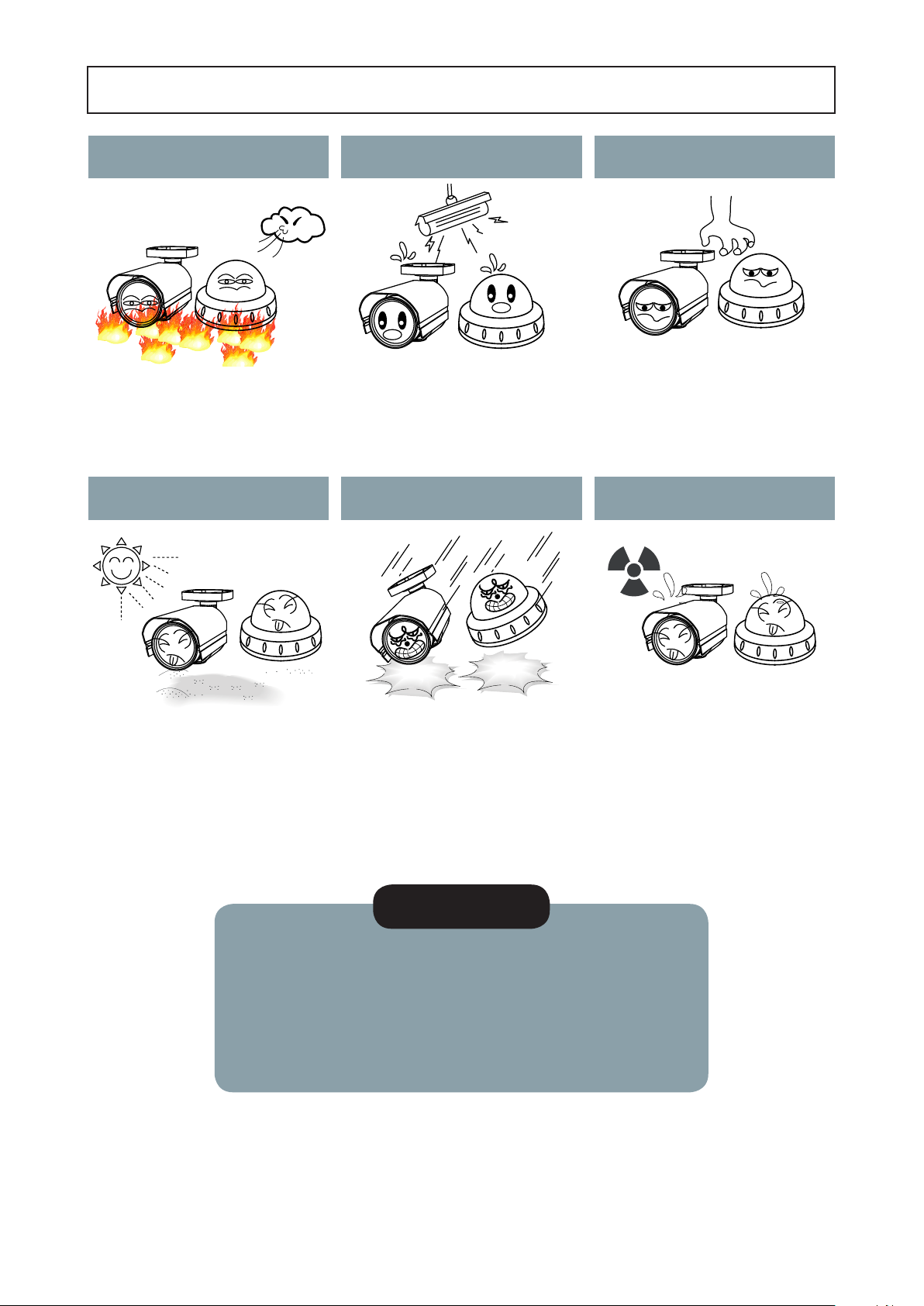
Precautions
Do not install the camera in
extreme temperature conditions.
Only use the camera under conditions
where temperatures are between
-10°C and +50°C. Be especially careful to
provide ventilation when operating under
high temperatures.
Never keep the camera pointed
directly at strong light.
Do not install the camera under
unstable lighting conditions.
Severe lighting change or flicker can
cause the camera to work improperly.
Do not drop the camera or subject
it to physical shocks.
Do not touch the front lens of the
camera.
This is one of the most important parts of
the camera. Be careful not to leave
fingerprints on the lens cover.
Do not expose the camera to
radioactivity.
It can cause malfunctions to occur.
* If the camera is exposed to spotlight or object reflecting strong light,
smear or blooming may occur.
* please check that the power satisfies the normal specification before
connecting the camera.
Housing damage can compromise
weatherproof ratings.
NOTE
If exposed to radioactivity the CCD
will fail.
- 2 -
Page 4
CAUTION
CAUTION
RISK OF ELECTRIC SHOCK
DO NOT OPEN
CAUTION:TO REDUCE THE RISK OF ELECTRIC SHOCK
DO NOT REMOVE COVER(OR BACK).
NO USER-SERVICEABLE PARTS INSIDE.
REFER SERVICING TO QUALIFIED SERVICE PERSONNEL.
ISO14001
CAUTION
RISK OF ELECTRIC SHOCK
DO NOT OPEN
CAUTION:TO REDUCE THE RISK OF ELECTRIC SHOCK
DO NOT REMOVE COVER(OR BACK).
NO USER-SERVICEABLE PARTS INSIDE.
REFER SERVICING TO QUALIFIED SERVICE PERSONNEL.
ISO14001
RISK OF ELECTRIC SHOCK
DO NOT OPEN
CAUTION:TO REDUCE THE RISK OF ELECTRIC SHOCK
DO NOT REMOVE COVER(OR BACK).
NO USER-SERVICEABLE PARTS INSIDE.
REFER SERVICING TO QUALIFIED SERVICE PERSONNEL.
ISO14001
The lightning flash with an arrowhead symbol, within an equilateral
triangle is intended to alert the user to the presence of uninsulated
dangerous voltage within the product's enclosure that may be of
sufficient magnitude to constitute a risk of electric shock to persons.
The exclamation point within an equilateral triangle is intended to alert
the user to the presence of important operating and maintenance
(servicing) instructions in the literature accompanying the appliance.
In USA and Canada, Use Class 2 Power Supply Only
INFORMATION - This equipment has been tested and found to comply with
limits for a Class A digital device, pursuant to part 15 of the FCC Rules & CE Rules.
These limits are designed to provide reasonable protection against harmful
interference when the equipment is operated in a commercial environment.
This equipment generates, uses, and can radiate radio frequency energy and, if
not installed and used in accordance with the instruction manual, may cause
harmful interference to radio communications.
Operation of this equipment in a residential area is likely to cause harmful
interference in which case the user will be required to correct the interference at
their own expense.
WARNING - Changes or modifications not expressly approved by the
manufacturer could void the user’s authority to operate the equipment.
CAUTION : To prevent electric shock and risk of fire hazards:
☞Do NOT use power sources other than those specified.
- 3 -
Page 5

Safety Instructions
Precautions for use
◑
This camera should be installed by qualied personnel only
◑
There are no user serviceable parts inside
◑
Do not disassemble this camera other than to make initial adjustments
◑
Use a UL approved regulated 24 volt AC or 12 volt DC power supply
◑
Use appropriate low voltage power cable to prevent re or electrical shock
◑
Please insure that your installation area can support the weight of the camera
Please handle this camera carefully :
◑
Do not use a strong or abrasive detergent when cleaning the camera
◑
Do not install near cooling or heating device
- 4 -
Page 6
Package Contents
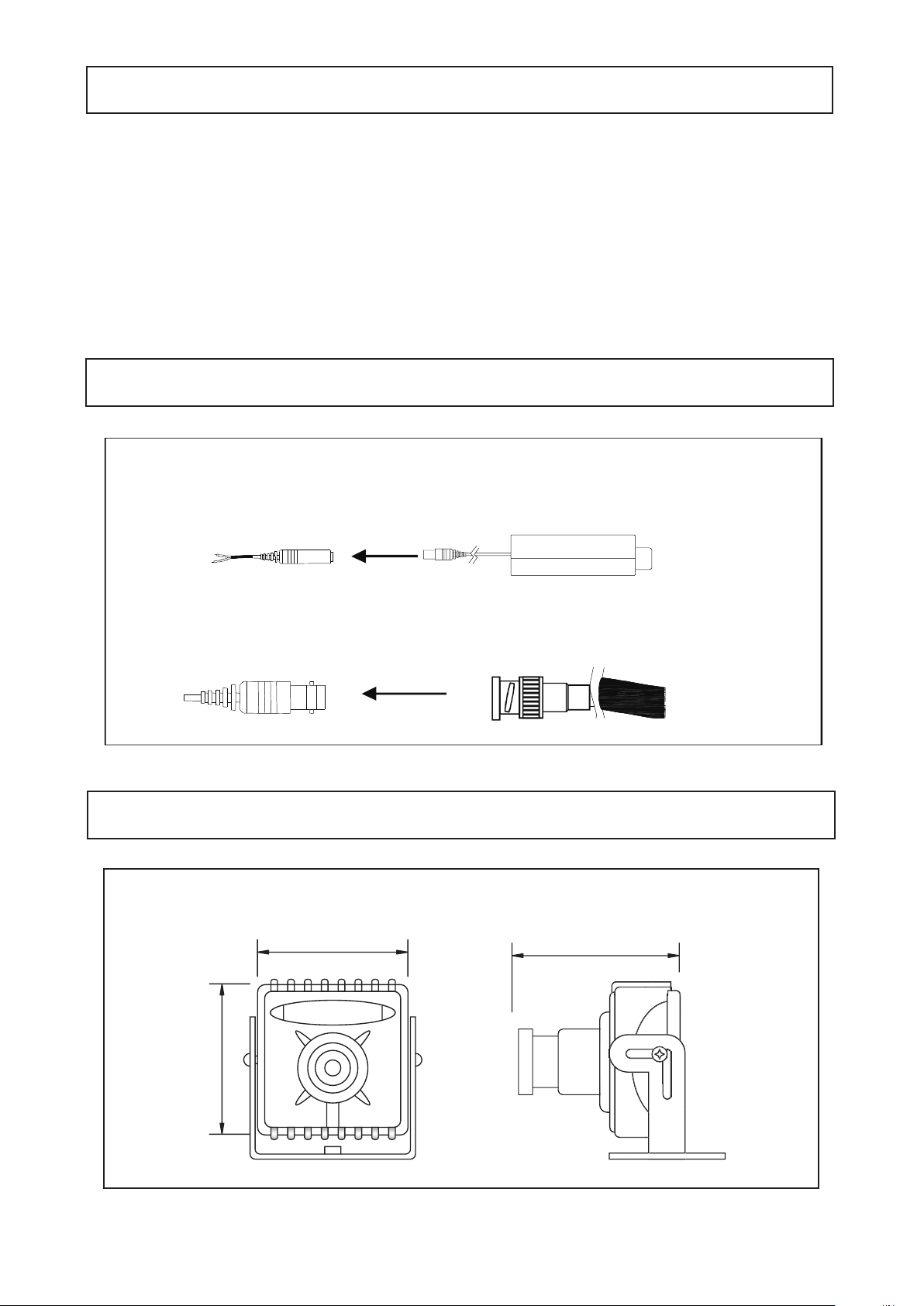
CONNECT POWER CABLE
1. WHEN USING 12 VOLTS DC (constant voltage 500 mA)
2. CONNECT VIDEO CABLE
- CONNECT BNC CABLE TO THE BNC JACK.
G
kjGXY}GwGz
wGpGaylk
jGaGORP
Please make sure that the following items are included in the Package:
WDR705H
• 1 Video Test Connector, Power Jack
• Set Screw
- 2 Tapping Screws M3x10
- 2 Machine Screws M2x3
CAMERA INSTALLATION
CAMERA DIMENSION
WDR705H
1.34”
1.34”
- 5 -
1.38”
Page 7
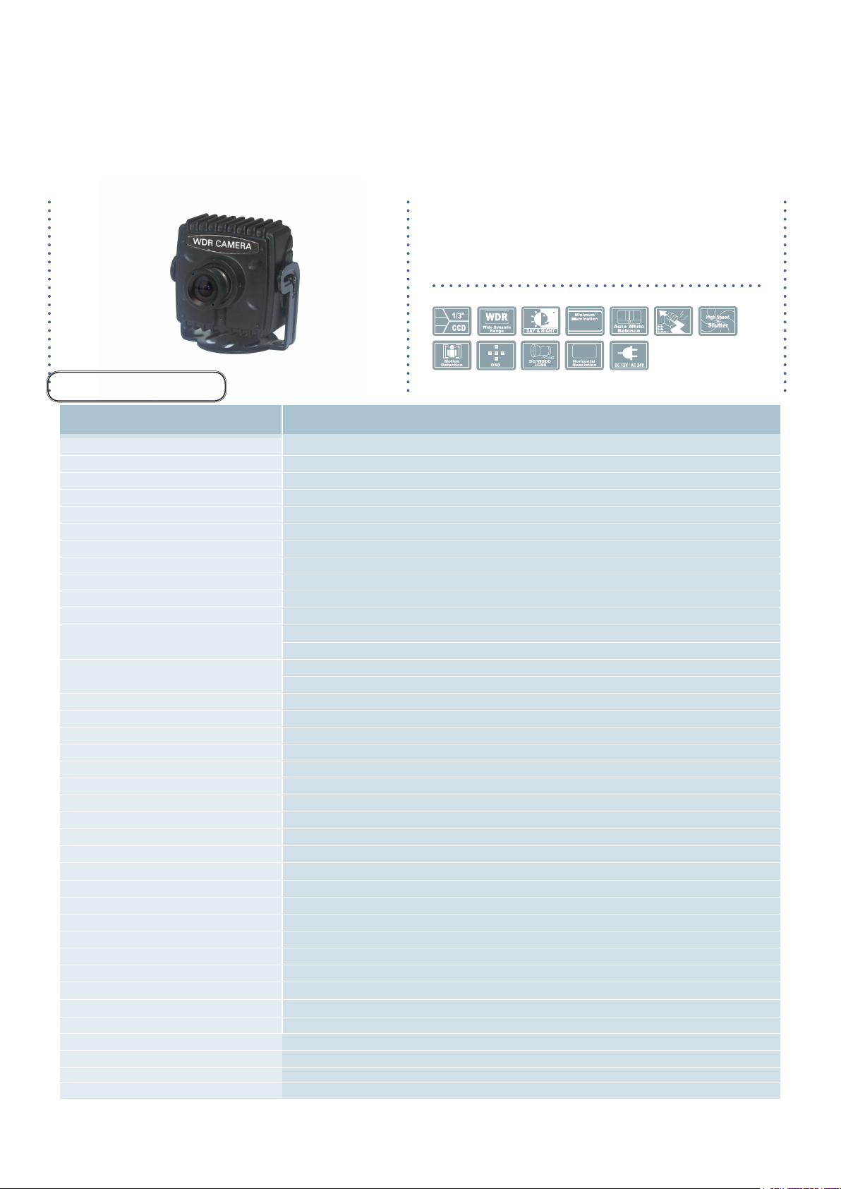
Speco Technologies
0.001Lux
700
0.001Lux
700
0.001Lux
700
(Miniature Camera)
4mm Fixed Board Lens
SPECIFICATIONS
WDR705H
■
MODEL
Image sensor
DSP / AFE
Total pixels
Effective Pixels
H. Resolution
Synchronizing system
Scanning system
Video output
Gamma Correction
S/N ratio
Minimum Illumination
Shutter/AGC
White balance
Scene Select function
2/3DNR
WDR / ATR-EX II
IR OPTIMIZER
EZOOM
DIS
PRIVACY MASK
MOTION Detection
FLIP
LCD / CRT
Camera ID
DEFOG
Flickerless
ANTI CR
Language
White pix mask
WDR / ATR-EX
Power Source
Operating Consumption
Operation Temperature / Humidity
Storage Temperature / Humidity
Dimension(mm)
Weight
WDR705H
1/3 Inch Super HAD CCD Ⅱ (ICX662, ICX663)
SONY CXD4141GG / CXD5148GG
NTSC : 1028(H) x 508(V)
NTSC : 976(H) x 494(V)
700TV Lines
Internal
NTSC : 525 Lines 2:1 Interlaced
1.0Vp-p Composite 75 Ohms
Standard γ =0.45
More than 50dB (AGC OFF)
Color: 0.1Lux (F1.2,50IRE,AGC ON); B/W:0.001Lux (F1.2,50IRE,AGC ON)
Auto : 1/50[s] 1/60[s] ~ 1/100,000[s]
Manual / Fix : 6~44.8[dB] / 2 ~ 256 FLD
1,800K ~ 10500K AUTO
ATW / PUSH / USER1 / USER2 / Manual / PUSH LOCK
FULL AUTO / INDOOR / OUTDOOR / BACKLIGHT / ITS / CUSTOM(OFF)
Adjusted to 0-6 steps
WDR / ATR-EX / OFF control
ON(AUTO, CENTER) / OFF
electronic zoom images to ON or OFF
Digital Image Stabilizer function ON/OFF selection
15 EA Privacy mask setting
4 frames Monitoring frame function / 96EA Dead band setting
Top bottom / Left right / Rotation by 180 degrees
Monitor type selection LCD / CRT
character string of up to 26 characters on 2 lines
ON / OFF
AUTO / ON / OFF
AUTO / ON / OFF
English / Spanish / Russian / Portuguese / German / French / Japanese
white pixel detection (AUTO / MANUAL / DATA CLEAR)
WDR / ATR-EX / OFF control
12VDC / 24VAC
DC 12V 160mA
-4ºF ~ +140ºF RH 95% Max
-4ºF ~ +140ºF RH 95% Max
1.34"(W) * 1.34"(H) * 1.38"(D)
0.78 lbs
- 6 -
Page 8
Scene Select
2D-DNR
Digital
R
eduction
Noise
DSP
2D-DNR
2D.3DNR
Digital
R
eduction
Noise
Resolution
Horizontal
700
DSP
2D-DNR
2D-DNR
Digital
R
eduction
Noise
Resolution
Horizontal
700
Tone Reproduction
Adaptive
ATR
DSP
2D-DNR
2D-DNR
Digital
R
eduction
Noise
Resolution
Horizontal
700
Tone Reproduction
Adaptive
ATR
Backlight
Compensation
BLC
DSP
2D-DNR
DSP
2D-DNR
2D-DNR
Digital
R
eduction
Noise
0.01 Lux
Illumination
Minimum
Resolution
Horizontal
700
Tone Reproduction
Adaptive
ATR
Backlight
Compensation
BLC
DSP
2D-DNR
OSD
Smart-IR
2D-DNR
Digital
R
eduction
Noise
0.01 Lux
Illumination
Minimum
Resolution
Horizontal
700
Tone Reproduction
Adaptive
ATR
Backlight
Compensation
BLC
DSP
2D-DNR
Smart-IR
General Features
Scene Select
Provide the best image automatically for every situation by intelligent scene analysis. Provide
the best image by automatic tuning for selected scene manually.
Digital
Noise
R
eduction
2D-DNR
2D.3DNR Filtering Method of Newly Advanced DNR Function
Newly developed 2D filtering enhances Digital Noise reduction at low light levels. 2D Filtering of
the Video Signal Optimises the Signal to Noise ratio.
700
Horizontal
Resolution
700TV Lines
The combination of a Sony Super HAD CCD image sen-sor and DNR DSP provides an excellent
resolution of 700 TV lines.
WDR
Wide Dynamic Range
WDR(Wide Dynamic Range)
WDR is a powerful and ultra advanced technology that captures cleaner and superior high
Resolution pic-tures even where images appear dark because there is a strong back light present.
BLC
Backlight
Compensation
Minimum
Illumination
0.01 Lux
OSD
High Spotlight BLC Function
High Spotlight BLC Function is Especially Effective to Read the Number Plate of the Vehicles in
the Street or Parking Lot at Night Time. Especially Users Can Adjust and Select the Special
Required Area to Observe the Target Object Under the Strong Spots of Light Exist.
Illumination
With an Incredibly Minimum Illumination of Amazing 0.01Lux can Capture Good Images Even in Extremely Low
Light Conditions and Related Noises are Significantly Reduced by the Ultra Advanced DNR
(Digital Noise Reduction)
Technology.
Additional Functions
OSD - On Screen Display menu with multi-Language support.
Privacy Masking -15 zones, Motion - 4 zones.
- 7 -
Page 9
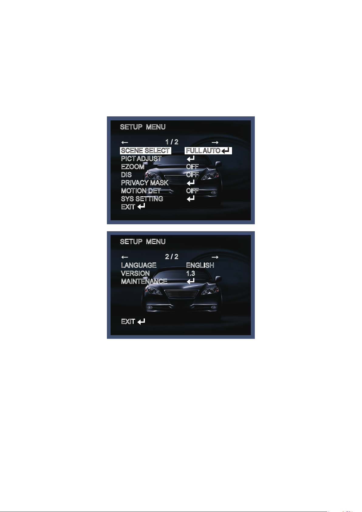
SETUP MENU
Menu items can be selected by using the OSD buttons of the camera
1. Press the Set Up button.
* The Set Up menu will be displayed on the monitor.
SETUP MENU
← 1 / 2 →
SCENE SELECT
PICT ADJUST
EZOOM
DIS
PRIVACY MASK
MOTION DET
SYS SETTING
EXIT
FULL AUTO
OFF
OFF
OFF
SETUP MENU
← 2 / 2 →
LANGUAGE
VERSION
MAINTENANCE
EXIT
ENGLISH
1.3
2. Move and select the required function using the Up and Down button.
* Move the arrow indicator Up or Down to select the desired feature by pressing
the Up or Down button.
- 8 -
Page 10
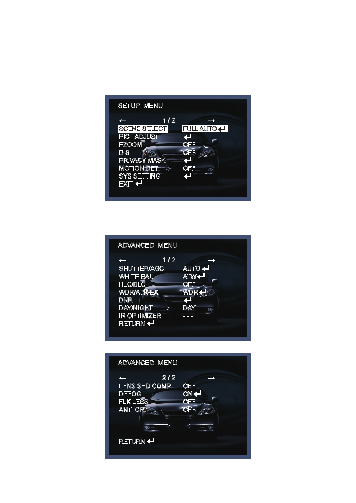
SCENE SELECT
Provide the best image automatically for every situation by intelligent scene analysis. Provide the best
image by automatic tuning for selected scene manually.
SETUP MENU
← 1 / 2 →
SCENE SELECT
PICT ADJUST
EZOOM
DIS
PRIVACY MASK
MOTION DET
SYS SETTING
EXIT
FULL AUTO
OFF
OFF
OFF
→ ADVANCED MENU
ADVANCED MENU
← 1 / 2 →
SHUTTER/AGC
WHITE BAL
HLC/BLC
WDR/ATR-EX
DNR
DAY/NIGHT
IR OPTIMIZER
RETURN
ADVANCED MENU
← 2 / 2 →
LENS SHD COMP
DEFOG
FLK LESS
ANTI CR
AUTO
ATW
OFF
WDR
DAY
- - -
OFF
ON
OFF
OFF
RETURN
- 9 -
Page 11
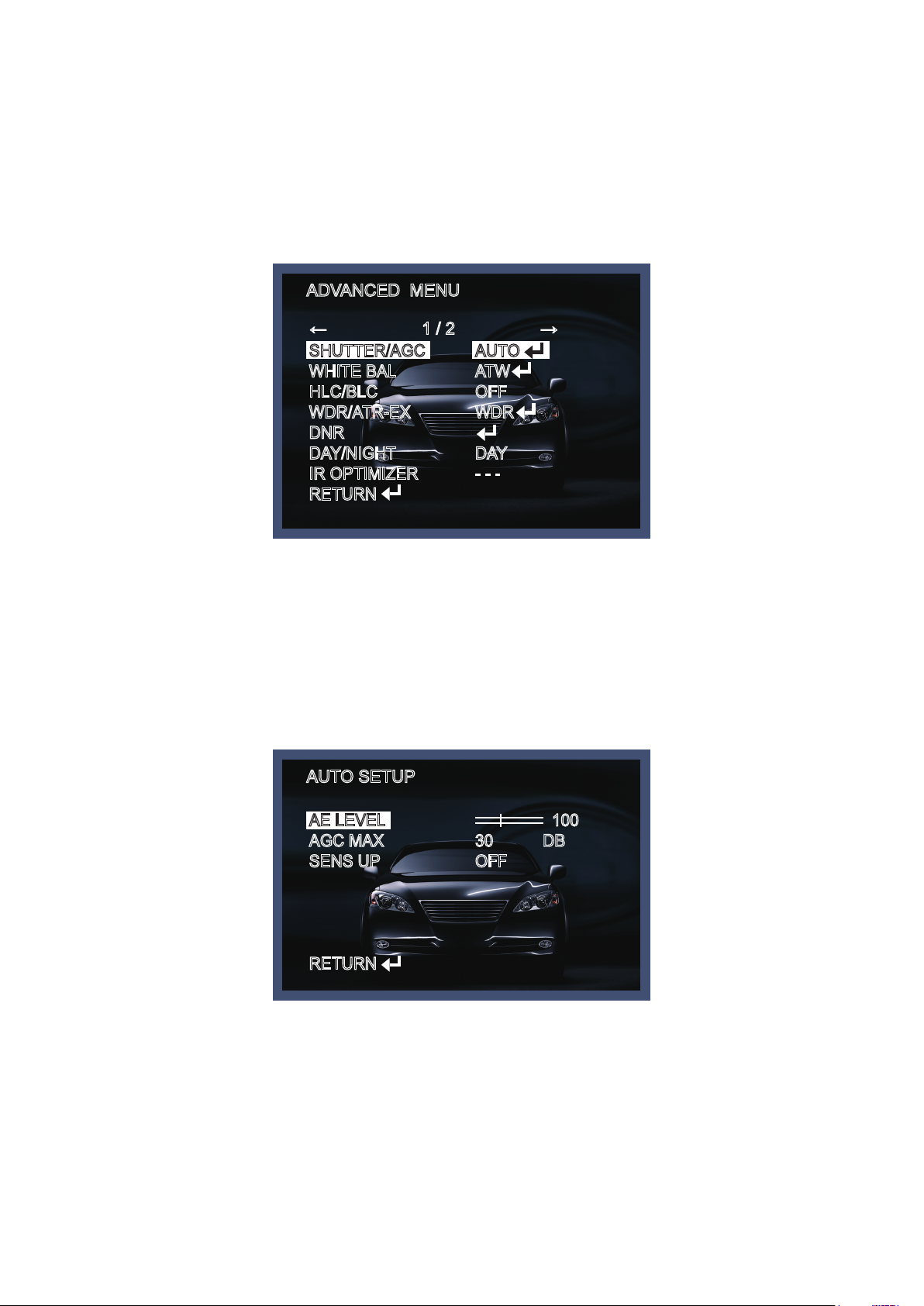
◆ SHUTTER/AGC
This function is used to select Automatic or Manual shutter speed control.
1. On the Set Up menu screen select SHUTTER/AGC by using the Up or Down button.
2. Select the desired shutter mode by pressing the Left or Right button.
ADVANCED MENU
← 1 / 2 →
SHUTTER/AGC
WHITE BAL
HLC/BLC
WDR/ATR-EX
DNR
DAY/NIGHT
IR OPTIMIZER
RETURN
AUTO
ATW
OFF
WDR
DAY
- - -
* AUTO
- AE LEVEL : Control of the brightness of bright lux.
- AGC(Auto gain control) MAX : Control of the brightness of dark lux.
- SENS UP : At night and/ or in dark condition, the sens-up will be helped to keep the clear image.
AUTO SETUP
AE LEVEL
AGC MAX
SENS UP
RETURN
100
30 DB
OFF
- 10 -
Page 12

* MANUAL
- SHUTTER : The function is used to control the light exposure.
- AGC MAX : The function is to control the brightness of dark lux.
* FIX
- SHUTTER : The function is used to control the light exposure.
- AGC : The brighter image can be displayed by adjusting AGC( Auto gain control) level.
◆ WHITE BAL
This function is used to set the white balance operation mode.
1. Move the arrow indicator to WHITE BAL on the SETUP menu screen using the Up and Down button.
2. Select the desired mode by using the Left or Right button.
ADVANCED MENU
← 1 / 2 →
SHUTTER/AGC
WHITE BAL
HLC/BLC
WDR/ATR-EX
DNR
DAY/NIGHT
IR OPTIMIZER
RETURN
ATW SETUP
SPEED
DELAY CNT
ATW FRAME
ENVIRONMENT
AUTO
ATW
OFF
WDR
DAY
- - -
127
030
128
INDOOR
RETURN
- 11 -
Page 13

* ATW : Auto tracking white, normal environment setting under fluorescent lamp or outdoors.
- SPEED : Select the start point of auto tracking speed and time by pressing the left or the right button.
- DELAY CNT : Select the start point of Auto tracking speed and time by pressing the left or the right
button.
- ATW FRAME : Set up the frame megnification by pressing the left or the right button.
- ENVIRONMENT : It improves color temperature chase accuracy in accordance with environmental
set-up. Select the environment by pressing the left or the right button.
* PUSH : Regardless of subject condition, adjust white balance. Always control locking mode with full-
in frame, white color as set point.
USER1 WB SETUP
B-GAIN
R-GAIN
RETURN
229
244
*User1, User2 : These are user defined modes the blue and red gains can be adjusted.
* MANUAL : The B and R gain values for manual WB are set on this screen.
MANUAL WB SETUP
LEVEL
41
RETURN
* PUSH LOCK : To get the most suitable status at current lighting environment, push the SET button
while camera focuses on a white plain paper.
- 12 -
Page 14

◆ HLC/BLC
ADVANCED MENU
← 1 / 2 →
SHUTTER/AGC
WHITE BAL
HLC/BLC
WDR/ATR-EX
DNR
DAY/NIGHT
IR OPTIMIZER
RETURN
HLC SETUP
AUTO
ATW
OFF
WDR
DAY
- - -
CLIP LEVEL
RETURN
00
* HLC : HLC, control and mask process for a strong light source. Select 0~255 by pressing the left or
the right button.
* BLC : Turn off or on the Back light compensation.
◆ WDR/ATR-EX
ADVANCED MENU
← 1 / 2 →
SHUTTER/AGC
WHITE BAL
HLC/BLC
WDR/ATR-EX
DNR
DAY/NIGHT
IR OPTIMIZER
RETURN
AUTO
ATW
OFF
WDR
DAY
- - -
- 13 -
Page 15

ATR-EX SETUP
CONTRAST
CLEAR FACE
RETURN
MID
MID
*ATR-EX
- CONTRAST : Increase bright illuminance and dark illuminance level over average value and then
control the contrast by selecting LOW, MID and high.
- CLEAR FACE : The function is to increase the lux when the object is in the back light.
WDR SETUP
CONTRAST
CLEAR FACE
MID
MID
RETURN
*WDR : The wide dynamic range (WDR) function of a camera is intended to provide clear images even
under back light circumstances where intensity of illumination can vary excessively, namely when there
are both very bright and very dark areas simultaneously in the field of view of the camera.
- CONTRAST : Increase bright illuminance and dark illuminance level over average value and then
control the contrast. Select the LOW, MID, HIGH by pressing the left or the right button.
- CLEAR FACE : The function is to increase the lux when the object is in the back light.
- 14 -
Page 16

◆ DNR
The level of DNR noise removal mode is getting higher, noise removal effect will be good, but ghost
effect may be shown up. Select 0~6 by pressing the left or the right button.
ADVANCED MENU
← 1 / 2 →
SHUTTER/AGC
WHITE BAL
HLC/BLC
WDR/ATR-EX
DNR
DAY/NIGHT
IR OPTIMIZER
RETURN
DNR SETUP
AUTO
ATW
OFF
WDR
DAY
- - -
LEVEL
RETURN
3
- 15 -
Page 17

◆ DAY/NIGHT
Picture can be displayed in either color of black and white.
1. Select DAY/NIGHT using the Up or Down button on the SETUP menu screen.
2. Select the desired mode using the Left and Right buttons.
ADVANCED MENU
← 1 / 2 →
SHUTTER/AGC
WHITE BAL
HLC/BLC
WDR/ATR-EX
DNR
DAY/NIGHT
IR OPTIMIZER
RETURN
AUTO
ATW
OFF
WDR
DAY
- - -
* DAY : Users can fix in DAY Mode.
* NIGHT : : Users can fix in Night Mode.
- BURST : Adjust color signal ON/OFF in night(B/W) mode.
D/N AUTO SETUP
BURST
DELAY CNT
DAY→NIGHT
NIGHT→DAY
RETURN
OFF
006
072
154
* AUTO
- BURST : Adjust color signal ON/OFF in night(B/W) mode.
- DELAY CNT(OPTION) : Sets the judgment time for transition between the Day and Night.
- DAY→NIGHT(OPTION) : Adjust the DAY→NIGHT switch level 0~255 by pressing the DAY→NIGHT
button.
- NIGHT→DAY(OPTION) : Adjust the NIGHT→DAY switch level 0~255 by pressing the NIGHT→D AY
button.
- 16 -
Page 18

◆ IR OPTIMIZER
ADVANCED MENU
← 1 / 2 →
SHUTTER/AGC
WHITE BAL
HLC/BLC
WDR/ATR-EX
DNR
DAY/NIGHT
IR OPTIMIZER
RETURN
IR OPTIMIZER SETUP
AUTO
ATW
OFF
WDR
DAY
- - -
MODE
IR AREA
LEVEL
IR LED
COLOR NIGHT
IR SHADE COMP
RETURN
AUTO
- - - -
06
DAY/NIGHT
OFF
OFF
- MODE : IR LED saturation is fixed positions or set the areas automatically.
- IR AREA : When the IR Optimizer is set in center on the mode menu, the intensity level can be
controlled by up, down, left and right.
IR AREA
TOP
BOTTOM
LEFT
RIGHT
WEIGHT
2
4
3
5
04
RETURN
- 17 -
Page 19

- LEVEL : The level of IR Optimizer can be controlled by selecting from 0 to 12.
- IR LED(OPTION) : IR LED can be select on or off.
- COLOR NIGHT : The function is to present the color in the night mode.
- IR SHADE COMP
→ PATTERN : Adjust the size of the IR LED area.
→ POSH : Adjust the IR LED area by left and right.
→ POSV : Adjust the IR LED area by Up and down.
→ LEVEL : Adjust the brightness when the IR LED is on.
IR SHADE COMP SETUP
◆ LENS SHD COMP
PATTERN
POSH
POSV
LEVEL
RETURN
ADVANCED MENU
← 2 / 2 →
LENS SHD COMP
DEFOG
FLK LESS
ANTI CR
SET2
480
246
MID
OFF
ON
OFF
OFF
RETURN
- 18 -
Page 20

LENS SHADE COMP SETUP
PATTERN
POSH
POSV
RETURN
SET1
480
246
- PATTERN : The function is to increase the brightness of outside of lens.
- POSH : Adjust the bright area by left and right .
- POSV : Adjust the bright area by up and down.
◆ DEFOG
This function helps to recognize the object in a foggy or dusty weather condition.
ADVANCED MENU
← 2 / 2 →
LENS SHD COMP
DEFOG
FLK LESS
ANTI CR
RETURN
DEFOG SETUP
LEVEL
OFF
ON
OFF
OFF
MID
RETURN
- 19 -
Page 21

◆ FLK LESS
The function is to prevent flickering automatically.
ADVANCED MENU
← 2 / 2 →
LENS SHD COMP
DEFOG
FLK LESS
ANTI CR
RETURN
FLK LESS SETUP
OFF
ON
OFF
OFF
◆ ANTI CR
COLOR rolling control.
MODE
RETURN
GAIN CNTL
- 20 -
Page 22

PICT ADJUST
Move the cursor to PICT ADJUST press the SET button.
SETUP MENU
← 1 / 2 →
SCENE SELECT
PICT ADJUST
EZOOM
DIS
PRIVACY MASK
MOTION DET
SYS SETTING
EXIT
PICT ADJUST
FULL AUTO
OFF
OFF
OFF
BRIGHTNESS
CONTRAST
SHARPNESS
HUE
COLOR GAIN
RETURN
128
32
08
064
128
◆ BRIGHTNESS
Adjust the brightness of camera from 0 to 255.
◆ CONTRAST
Adjust the contrast level 0~063 by pressing the left or the right button.
◆ SHARPNESS
Adjust the sharpness level 0~015 by pressing the left or the right button.
◆ HUE
Adjust the color level 0~127 - RED, GREEN, BLUE, YELLOW, CYAN, MAGENTA.
- 21 -
Page 23

◆ COLOR GAIN
Adjust the color tone density from 0 to 255.
EZOOM
SETUP MENU
← 1 / 2 →
SCENE SELECT
PICT ADJUST
EZOOM
DIS
PRIVACY MASK
MOTION DET
SYS SETTING
EXIT
FULL AUTO
OFF
OFF
OFF
EZOOM SETUP
MAG
PAN
TILT
RETURN
- MAG : (x1 ~ x256) Digital Zoom.
- PAN : Left and right control level 0~1023.
- TILT : Up and down control level 0~511.
000
510
256
- 22 -
Page 24

DIS
Image stabilization
SETUP MENU
← 1 / 2 →
SCENE SELECT
PICT ADJUST
EZOOM
DIS
PRIVACY MASK
MOTION DET
SYS SETTING
EXIT
FULL AUTO
OFF
OFF
OFF
PRIVACY MASK
Hide an area you want to hide on the screen.
When the PRIVACY menu screen is displayed, press the Up and Down buttons to set to PRIVACY.
SETUP MENU
← 1 / 2 →
SCENE SELECT
PICT ADJUST
EZOOM
DIS
PRIVACY MASK
MOTION DET
SYS SETTING
EXIT
FULL AUTO
OFF
OFF
OFF
- 23 -
Page 25

PRIVACY MASK SETUP
AREA SEL
DISPLAY
POSITION
COLOR
TRANSP
MOSAIC
RETURN
◆ AREA SEL
Selects the mask frame to be adjusted.
◆ DISPLAY
Display the mask frame.
◆ POSITION
1/15
OFF
- - - -
- - - -
- - - -
- - - -
PRIVACY MASK field set-up
◆ COLOR
Sets the colors of the mask frames.
It selects the palette values below (where m: 0-7, color setting - 1) for settings 1 to 8.
◆ TRANSP
Sets the transparency ratio of the mask frames.
The same transparency ratio value is set for all the mask frames.
◆ MOSAIC
Sets the mask frame mosaic function to ON or OFF.
OFF: Mosaic function OFF
ON: Mosaic function ON
- 24 -
Page 26

MOTION DETECTION
SETUP MENU
← 1 / 2 →
SCENE SELECT
PICT ADJUST
EZOOM
DIS
PRIVACY MASK
MOTION DET
SYS SETTING
EXIT
MOTION DETECTION
FULL AUTO
OFF
OFF
OFF
DETECTION SENSE
INTERVAL
BLOCK DISP
MASK AREA
MONITOR AREA
RETURN
111
000
OFF
* DETECT SENSE : Motion detection strength level 0~127 control.
* INTERVAL : Set the interval of Motion sense.
* BLOCK DISP : Controls the ON/OFF status of the motion detection block display.
* MASK AREA : Set the area from 1 to 96.
* MONITOR AREA : Sets whether to use the monitoring frames.
- AREA SEL 1/4 : Selects the monitoring frame be set.
- MODE
OFF: The monitoring frames are not used.
ON: The monitoring frames are used.
- TOP : Sets the top side of the monitoring frame selected by the AREA SEL parameter.
- BOTTOM : Sets the bottom side of the monitoring frame selected by the AREA SEL parameter.
- 25 -
Page 27

- LEFT : Sets the left side of the monitoring frame selected by the AREA SEL parameter.
- RIGHT : Sets the right side of the monitoring frame selected by the AREA SEL parameter.
MONITOR AREA
AREA SEL
AREA MODE
TOP
BOTTOM
LEFT
RIGHT
RETURN
SYSTEM SETTING
SETUP MENU
← 1 / 2 →
SCENE SELECT
PICT ADJUST
EZOOM
DIS
PRIVACY MASK
MOTION DET
SYS SETTING
EXIT
1/4
OFF
03
04
04
08
FULL AUTO
OFF
OFF
OFF
SYSTEM SETTING
LENS
FLIP
LCD/CRT
COMMUNICATION
CAMERA ID
RETURN
- 26 -
AUTO
OFF
CRT
OFF
Page 28

◆ LENS
You can select Manual or Auto mode depending on the lens type.
◆ FLIP
Select the image of up and down, left and right and reverse.
◆ LCD/CRT
Set the monitor of output
◆ COMMUNICATION(Optional)
COMMUNICATION
PROTOCOL
ADDRESS
BAUDRATE
DATABIT
PARITY
STOPBIT
RETURN
* PROTOCOL : Pelco-D
* ADDRESS : Set the protocol address.
* BAUDRATE : Set the speed of transfer.
* DATABIT : 8BIT is fixed.
* PARITY : Set the parity.
* STOPBIT : 1BIT is fixed.
PELCO-D
001
38400
8BIT
OFF
1BIT
- 27 -
Page 29

◆ CAMERA ID
To select the position where the camera ID should be displayed on the screen.
Move the cursor to POS and press the SET button.
CAMERA ID SETUP
ABCDEFGHIJKLMNOPQRSTUV
WXYZ0123456789!”#$%&’(
) _ ` ,¥ : ; <=>?@\^*↑↓←→/
CHR1 CHR2
←→↑↓ CLR POS
RETURN
* A - )Each user font: A selected character is registered at the position selected by the CAMERA ID
cursor when the Enter operation input is performed from the status in which the characters have been
selected using the character selection cursor. The camera ID cursor then moves one character to the
right.
* ← → ↑ ↓:The camera ID cursor moves in the direction of the arrow when the Enter operation input
is performed from the status in which ←, →, ↑ or ↓ has been selected using the character selection
cursor.
* CLR:The character selected by the camera ID cursor is cleared when the Enter operation input is
performed from the status in which CLR has been selected using the character selection cursor.
* POS:The display switches to the camera ID display position setting screen when the Enter operation
input is performed from the status in which POS has been selected using the character selection cursor.
On the camera ID display position setting screen, the camera ID display position is changed in real
time in response to the left, right, up or down operation input. When the Enter operation input is
performed, the display position is entered, and the display returns to the camera ID setting screen.
- 28 -
Page 30

LANGUAGE
Selects the language in which to display the internal OSD menu.
The menus can be changed in real time in the selected language.
SETUP MENU
← 2 / 2 →
LANGUAGE
VERSION
MAINTENANCE
EXIT
ENGLISH
1.3
VERSION
This number can check the specifications of the camera.
SETUP MENU
← 2 / 2 →
LANGUAGE
VERSION
MAINTENANCE
EXIT
ENGLISH
1.3
- 29 -
Page 31

MAINTENANCE
SETUP MENU
← 2 / 2 →
LANGUAGE
VERSION
MAINTENANCE
EXIT
◆ W.PIX MASK : The function is to control and compensate the white spots.
ENGLISH
1.3
MANUAL COMP
REGISTRATION
REG. POINT
CUSRSOR COLOR
BLINK
REG. NUMBER
RETURN
OFF
WHITE
OFF
3 / 64
*MANUAL
- REGISTRATION : Compensate the white spots.
- REG. POINT : Select the color of compensated white spots.
- CUSRSOR COLOR : Control the color of cursor when the white spot is compensated.
- BLINK : Control the blink of cusrsor.
- REG. NUMBER : The number of compensated white spots.
- 30 -
Page 32

* AUTO
AUTO COMP
LEVEL1
LEVEL2
AUTO
RETURN
008
255
◆ CAMERA RESET
This function initializes all the internal OSD menu settings together.
- 31 -
Page 33

●
Trouble Shooting
PROBLEM
Nothing appears on
the screen.
The image on the
screen is dim.
The image on the
screen is dark.
The camera is not
working properly
and the surface of
the camera is hot.
POSSIBLE CAUSE
☞
Check the power cable, power supply output and video
connection between the camera and monitor.
☞
Are the camera lens or the lens glass dirty?
Clean the lens / glass with a soft clean cloth.
☞
Adjust the monitor controls, as required.
☞
If the camera is facing a very strong light, change
the camera position.
☞
Adjust the lens focus.
☞
Adjust the contrast control of the monitor.
☞
If there is an intermediate device, correctly set the 75Ω/Hi-z.
☞
Check the camera is correctly connected to an appropriate
regulated power source.
Motion Detection
is not activated.
The color of the
picture is not correct.
The image on the
screen ickers.
The SENS-UP does
not work.
☞
Has MOTION DET been set to ON in the menu?
☞
Has MD AREA been properly dened?
☞
Check the settings in WHITE BALANCE menu.
☞
Make sure that the camera isn’t facing direct sunlight or
uorescent lighting. If necessary,change the camera position.
☞
Check that the AGC setting in the EXPOSURE menu is’t set to OFF.
☞
Check the EXPOSURE menu and make sure SHUTTER is set to------.
- 32 -
Page 34

- 33 -
Page 35

- MEMO -
- 34 -
Page 36

200 New Highway
Amityville, NY 11701
631-957-8700
1 800 645 5516
www.specotech.com
 Loading...