

Page 1
VLBT5W /VL BT6 W/
VLDT5W/V LDT 6M/ VLT7W
User Manual
Tha nk you fo r purch asing o ur prod uct. Sp eco Techn ologi es is con stant ly deve lopin g and
imp rovin g produ cts. We res erve th e right t o modif y produ ct desi gn and sp ecifi catio ns
wit hout no tice an d witho ut incu rring a ny obli gatio n.
Page 2

Warnings
If th e produ ct does n ot work p roper ly, plea se con tact t he dea ler or w here t he pro duct w as pur chas ed.
■
Spe co Techno logie s is not re spons ible fo r any pro blems c aused b y impro per ope ratio n or repa ir.
Kee p away fr om liqu id whil e in use.
■
■ All i nstal latio n and ope ratio n here sh ould co nform t o local e lectr ical sa fety co des.
■ Mak e sure th e power s upply v oltag e is corr ect bef ore usi ng the ca mera.
■ Do no t drop th e camer a or subj ect it to p hysic al shoc k.
■ Do no t use the d evice b eyond s pecif ied vol tage ra nge.
■ Do not place the camera in extre mely hot, cold (the oper ating temper ature shall be (-4˚F ~122˚F), dus ty or
damp locat ions, and do not expose it to high elect romagnet ic radiation .
■ To avo id hea t accu mula tion , good v enti lati on is re quir ed for o pera ting e nvir onme nt.
Intro duction
Thi s camer a serie s is the la test te chnol ogy and a dvanced circu it design, which fea tures high defin ition and
sensi tivity, low no ise and d istor tion an d suppo rts HD vi deo tra nsmis sion wi th the co mmon co axial c able,
ens uring t he requ ireme nt of the H D monit oring i n the tra ditio nal sur veill ance sy stem.
● Hig h Resol ution
Ado pt high p erfor mance s ensor, p rovid ing hig h defin ition a nd clea r image .
● Hig h Tran smiss ion Per forma nce
Rea l-tim e trans missi on with h igh spe ed and lo ng dist ance.
● Hig h Light C ompen satio n (HLC)
Mas k and com pensa tion th e high li ght are a.
● DNR
Red uce noi se from b right ness an d color s ignal .
● OSD
Acc ess the c amera s ettin gs whic h can be cl early d ispla yed thr ough th e main me nu.
● Whi te Bala nce
Adj ust the c olor te mpera ture ac cordi ng to the e nviro nment a utoma tical ly.
● ICR A uto Swi tch
The f ilter w ill fil ter inf rared l ight du ring th e dayti me and ch ange to n ormal a t nigh t to
ens ure a hig h sensi tivit y and cle ar imag e.
● AGC
Adj ust the g ain of am plifi er, enab ling th e camer a to outp ut the st andar d video s ignal i n diffe rent
lig hting c ondit ion.
● Wid e Dyna mic Ra nge (W DR)
Whe n there a re both v ery bri ght and v ery dar k areas s imult aneou sly in th e field o f view, th is fun ctio n
wil l balan ce the br ightn ess lev el and pr ovide c lear im ages.
1
Page 3
● Pri vacy Ma sking
Thi s funct ion all ows you t o block o r mask ce rtain a rea of a sc ene for p rivac y purpo se.
● Bac kligh t Compe nsati on (BLC )
Whe n the bac k of the ca pture d objec t is too mu ch brig ht, you c an set BL C for the c aptur ed obje ct to
mak e it clea rer.
● Mot ion Det ectio n
The a larm wi ll be tri ggere d when th ere are m oving o bject s captu red by th e camer a.
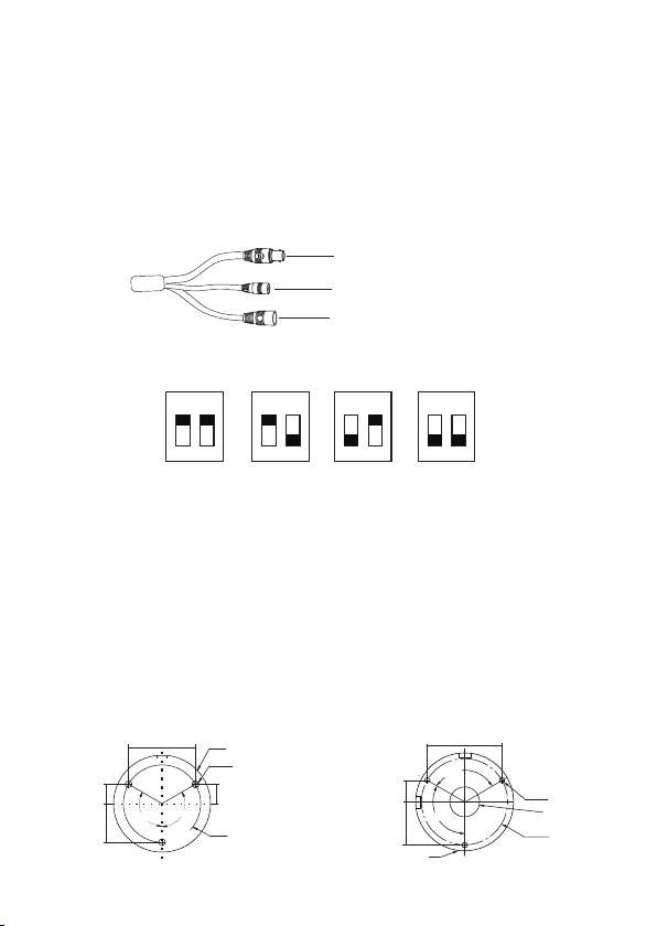
Cables
Vide o Outpu t
Vide o Switc h Cable
Pow er Cabl e
Vide o Switc h: Remo ve the c over o f the vi deo sw itch ca ble an d set th e vide o outp ut as be low.
ON ON ON O N
2 2 2 2
1 1 1 1
AH D TVI CV I
CV BS
Installation
Bef ore you s tart, p lease m ake sur e that th e wall or c eilin g is st ron g eno ugh to w ith sta nd t hre e tim es
th e wei ght of t he camera . Please install and use the camera in the dry environme nt.
You’d b etter i nstal l back th e lens co ver or lo wer dom e less th an 4 hours aft er removi ng it.
The mo unting typ es of camer as are only f or refer ence.
►Mounting for VLBT5W/VLBT6W
1. Drill the scre w holes and the cab le hole on the wall accordin g to the dr ill tem plate .
62. 5mm
120°
120°
∅82.0
VLBT6W
12.9 mm
25.5 mm
44.2 mm
120°
VLBT5W
∅64.0
∅4.5
12.9 mm
120°
∅51.0
18. 1mm
36. 1mm
2
∅4.6
∅25.1
∅72.2
Page 4
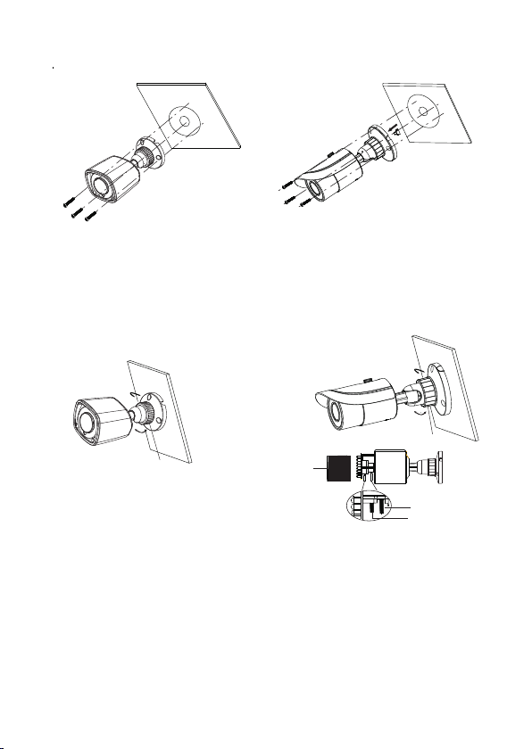
2. Rou te and conn ect the cab les .
3. Secure the mou nting base with came ra to the wall with scr ews as shown be low.
4. Bracke t adjus tment. Befor e adjus tment, previ ew the image of the camera on a monitor and then loo sen the
fixed rin g to adjust the vie w angle of the c amer a. Tighten the fixed ring aft er the adjustmen t.
5. Fo cus and z oom adj ustme nt ( If the c amera y ou get is f ixed le ns, ple ase ski p this st ep). Re move th e
len s cover a nd then a djust t he focu s and zoo m screw s to get a cl ear ima ge. Fin ally, ti ghte n thes e two
scr ews and t he lens c over.
Pan 3 60°
Pan 3 60°
Til t 90°
Til t 90°
Fix ed Ring
Len s Cov er
Fix ed Ring
Zoo m
Foc us
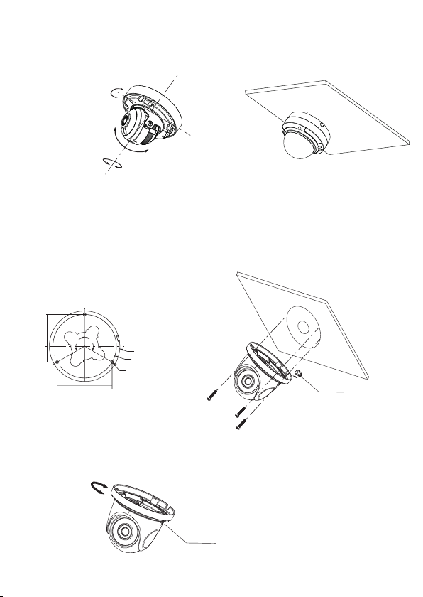
►Mounting for Dome Camera
● Mounting for VLD T6W
1. Loo sen the scr ews to open the lower d ome and th en loose n the lo ck scre w to remov e the mo unti ng bas e.
2. Att ach th e dril l temp late t o the place wh ere yo u want t o fix th e camer a and th en dri ll 4 scr ew hol es
and 1 c able h ole (i f you wa nt to ro ute the cabl es thr ough t he mou nting base ) acco rdin g to the d rill
tem plat e.
3
Page 5

88 mm
∅6
∅148
89mm
∅22
Lo ck Sc rew
Lo wer D ome
3. And th en secur e the mo untin g ba se to the c eili ng or wal l wi th the sc rews
Rou te and conn ect the cab les.
pro vide d.
Sp ong e
Mo unt ing B ase
4. Fix th e camera to t he mount ing base wi th the lock s crew.
5. Th ree- axis a djus tmen t. Bef ore ad just ment , prev iew th e imag e of the c amer a on a monitor and the n
adjus t the camer a accor ding to the figure below to get an optim um angle.
Ti lt 0° ~75 °
Ro tat ion 0 °~3 60°
Pa n 0°~ 360 °
4
Page 6

7. Ins tall the lo wer dome ba ck to the came ra with the sc rews an d r em ov e t he pr ot ec ti on
fi lm sof tl y to co mpl et e th e i nst al lat io n.
● Mounting for VLD T5W
1.
Drill the screw holes and the cable hole on the wall according to th e dril l tem plate.
2. Loose n the screw s to re move t he lo wer dome fr om the came ra.
(mm)
5
74.2
25
.
4
7
Lower Dome
3
. Rou te and co nnect t he cabl es.
4. Secure the mo unting bas e with came ra to the wal l with scre ws as shown b elow.
Rub ber Pl ug
5
Page 7
Thr ee-ax is adju stmen t. Befo re adju stmen t, prev iew the i mage of t he came ra on a mon itor an d then
5.
adj ust the c amera a ccord ing to th e figur e below t o get an op timum a ngle.
6. In stall t he lowe r dome ba ck to the c amera a nd secu re it wit h the scr ews.
Pan 0 °~3 55°
Rot ati on 0°~ 355 °
Til t 0° ~67°
● Mounting for VLT7W
1. Drill the scre w holes and the cab le hole on the wall accordin g to th e drill t empla te.
2. Ro ute and c onnec t the cab les. Th en sec ure th e came ra to th e ceil ing or w all wi th the s crew s prov ided .
48. 7mm
24. 4mm
3.
Adjust the camera to obtain an optimum angle by loosening the lock screws. Before adjustment, preview the
image of the camera on a monitor. Tighten the lock screws after you finish adjusting the view angle of the camera.
120°
84.4mm
120°
∅4.5
∅108
∅97.5
Rub ber Plu g
Loc k Scr ew
6
Page 8

Specifications
Spe cific ation s
Cam era
Ima ge Sens or
Res oluti on
Ima ge size
Vide o Outpu t
Ima ge Syst em
Ele ctron ic Shut ter
IR Di stanc e (feet )
Fra me Rate
Min . Illum inati on
Len s
Len s Mount
S/N R atio
Ing ress Pr otect ion
Fun ction s
Fun ction C ontro l
Day & Night
WDR
Dig ital NR
Glo bal Exp osure
Cen tral Ex posur e
AGC
Aut o Whi te Bala nce
BLC
Front Lig ht Compensat ion
Sha rpnes s
Sma rt IR
Def oggin g
HLC
Ima ge Sett ing
Def ect Cor recti on
Oth ers
Pow er Supp ly
Pow er Cons umpti on
Work ing En viro nmen t
Dim ensio ns (inc h)
Mod els
VLB T5W VLBT6W VLD T6M VLD T 5W VLT7W
1/2 .8" COM S
2MP
192 0×108 0
AHD /TVI/ CVI/C VBS (*c amera c omes de fault ed to HD- TVI)
PAL/N TSC
Aut o; 1/50 s~1/1 00000 s(PAL); 1/60s ~1/10 0000s ( NTSC)
32. 8~65. 6 ~98 .4
30f ps(60 Hz),2 5fps( 50Hz)
Col or:0. 001lu x@F1. 2, AGC ON; B /W: 0lux w ith IR
2.8 mm 2.8~ 12mm
M12 D 14
52d B(AGC O FF)
≥
IP6 6 IP66 IP 66&IK 10 IP66 &IK10 I P66
OSD ( UTC con trol)
ICR
Yes (12 0dB)
Yes
Yes
Yes
Yes
Yes
Yes
Yes
Yes
Yes
Yes
Yes
Yes
Aut o
DC1 2V (± 10%)
IR OF F: < 1W; IR O N : < 4W
-4 °F ~ 1 22 °F, 10 % ~ 90 % (rel ativ e humi dity )
Ф 2.7 6 6.1 4
65. 6 65.6 ~98.4 32. 8~65. 6 32. 8~65. 6
2.8 ~12mm
(mo toriz ed)
D14 M12 M12
×
Ф5. 90 4.49×Ф3. 43 8.6 2×
2.8 mm 2.8m m
Ф4. 61 3.54×
Ф3. 43 4. 25×
7
 Loading...