

Page 1
VLD1TW Manual
Page 2
Thank you for purchasing a Speco Technologies HD-TVI camera. Please
read this manual carefully for correct use of the product and keep it
for reference purposes.
►Warnings and Cautions
■ Disclaimer
■ Avoid Electric Shock
■ Avoid excessive moisture
■ Do not use camera beyond prescribed voltage range.
Page 1
■ Never attempt to disassemble the camera privately.
Speco Technologies is constantly developing and improving products.
We reserve the right to modify product design and spe cifications
without notice and without incurring any obligation.
To prevent electric shock, do not remove screws or cover.
Do not use strong or abrasive detergents when cleaning camera body.
Clean with dry cloth or mild detergent, wiping gently.
Only use recommended power supply. Ensure power input source
conforms to local voltage. Voltage outside of range could cause
damage or cause abnormal performance.
It may result in internal components being damaged.
VLD1TW
User Manual
Page 3
between -4*F and +140*F.Provide
Page 2
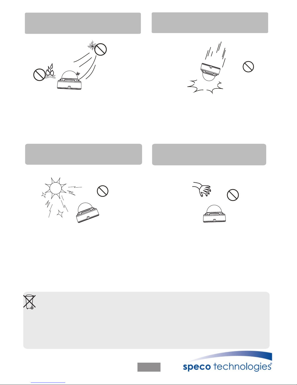
Use only under temperature conditions
good ventilation when using in high
temperature conditions.
Do not drop the camera or subject it to
physical shock.
It may cause production malfunction.
Do not aim camera at sun or extra
bright place.
Strong light will degrade image quality
and could cause damage.
Avoid touching the camera lens.
The lens is the most important component
of the camera. Be careful not to smear it
with fingerprints.
Do not place the camera in extreme hot
or cold environment.
Correct Disposal of This Product
If the camera no longer functions or can no longer be repaired, it must be disposed
of according to regulations reading electronic waste. By not disposing of electronic
items in household waste you will not only be following the law, but contributing
the protection of the environment.
Page 4

► Components and Accessories
Camera
User manual
Screwdriver
Drill Template
Adapter Plate
Screws
► Overview
Page 3
3
4
5
6
7
8
1
2
Mounting Base
1
2
3
Video Cable
Lock Screw
Power Cable
Lower Dome
4
5
6
7
8
Focus
Zoom
Lens
Page 5

► Connecting to Monitor
► Connecting to Power
Connect the adapter to the power input connector in accordance with the
camera. The recommended adapter specification for the camera is DC12V.
Page 4
Video
HD-TVI
VIDEO IN
HDMI
VGA
TVI DVR
Monitor
DC12V
Power
Page 6

Before you start, please make sure that the wall or ceiling is strong enough to
withstand three times the weight of the camera.
► Installation
*
Page 5
1. Loosen the screws to open the lower dome and then loosen the lock screw
to remove the mounting base.
2. Attach the drill template to the place where you want to fix the camera and
then drill 4 screw holes and 1 cable hole (if you want to route the cables
through the mounting base) according to the drill template.
3.
secure the mounting base to the ceiling or wall with screws.
Route the cables and connect the power cable and video cable. And then
Ceiling or Wall
Lock Screw
Lower Dome
∅6
∅148
∅22
88 mm
89mm
Page 7

* This installation should be made by a qualified service person and should
confirm to all local codes.
Page 6
5. Three-axis adjustment. Before adjustment, preview the image of the camera
on a monitor and then adjust the camera according to the figure below to get
an optimum angle.
6. Adjust the Focus and Zoom screw to get a clear image (if your camera is
prime lens,please skip this step).
Ceiling or Wall
Focus
Zoom
Rotation 0°~360°
Pan 0°~360°
Tilt 0°~75°
7. Install the lower dome back to the camera with the screws and remove
the protection film softly to complete the installation.
4. Fix the camera to the mounting base with the lock screw.
Page 8

When the arrow is pointed upward, the image will be right side up.
Lens controllers are located in Top direction of image.
Page 7
Page 9

► Features
This series of cameras adopt the latest HD-TVI technology and advanced
circuit design, feature high definition and sensitivity, low noise and
distortion and support HD video transmission with the common coaxial
cable, ensuring the requirement of the HD monitoring in the traditional
surveillance system.
● High Transmission Performance
Real-time transmission with high speed and long distance.
● ICR Auto Switch
The filter will filter infrared light during the daytime and change to
normal at night to ensure a high sensitivity and clear image.
● Color-B/W Auto Switch
The camera will display color image in daytime and become monochrome
automatically at night.
● Auto White Balance
Ad j u s t the c o lor te m p e r ature ac c o r ding to the e n v ironment
automatically.
● DNR
Reduce noise from brighteness and color signal.
● High Resolution
Adopt high performance HD-TVI sensor, providing high definition
and clear image, up to 1080P resolution.
Page 8
Page 10

Model
Image Sensor
Pixels
Signal System
Min. Illumination
Lens
IR Visible Distance
IP Rank
Video Out
Resolution
Frame Rate
ICR
DNR
S / N Ratio
Electronic Shutter
AGC
White Balance
Power
Temperature
Humidity
Dimension
VLD1TW
1 / 3 '' CMOS
1920 x 1080
PAL / NTSC
0 Lux ( LED ON )
2.8 ~ 12 mm
66 ~ 98 feet (depending on scene reflection)
IP 66
TVI 2.0 and CVBS (960H) video output
1080 P ( 1920 x 1080 )
30 fps ( 60Hz ), 25 fps ( 50Hz )
Yes
Yes
> 52 dB ( AGC OFF )
Yes
Auto White Balance
DC12V ± 10%
- 4*F ~ 104*F
10% ~ 90%
5.9'' x 4.5''
1 / 50s ~ 1 / 67500s
► Specifications
Page 9
 Loading...