

Page 1

VLB11SCSFF
550 Line Color Bullet Camera
Focus Free
Wall & Ceiling Mountable
Please read this manual thoroughly before operation and keep
it handy for further reference.
Page 2
DO NOT use power sources other than that specified._____ _
The ligh ting flas h with an arr owhead symbol, within an equilat eral triangle is
Intend ed to alert the user to the presence of un-insulated “dangerous voltage”
within the product’s enclosure that may be of sufficient magnitude to c onstitute
a risk of ele ctric sho ck to person s____ ___________________ _____________
The exclamation point within an equilateral triangle is intende d to alert the user
to the presence of important operating and maintenance (serving) instructions
in th e l ite ra tu re a cco mp an yi ng th e a pp li an ce __ __ __ __ __ __ ___ __ _
I NF OR MA T I ON -T hi s eq ui pm en t h as b ee n t es te d an d fo un d t o co mp an y w it h
l im i t s f or a c la s s a d ig i t a l d e vi ce P ur su an t t o p ar t 1 5 o f t he F CC r ul es .
T h e s e l i m i t s a re d es ig ne d t o p ro vi d e r ea so n a bl e pr ot ec ti o n a ga in st h ar mf ul
I nt er fe re n c e W he n t he e qu ip me nt s o pe ra te d i n a c om m e rc i a l e n v i r o n m e n t .
T hi s e qu ip m en t g ene ra te s, u s es , a nd Ca n R ad ia te r ad io f req ue nc y e ne rg y a nd
if no t i nst al le d a nd us e d in ac cor da nc e w it h th e i nst ruc ti on m anu al, ma y C au se
Ha rm fu l i nt er fe re nc e to ra d io co mmu ni c at io ns . O pe ra tio n o f t hi s eq uip men t i n a
r e s i d e n t i a l a r e a i s l i k e l y t o c a u s e h a r m fu l i n t e r f e r e n c e i n w h i c h
Ca se t he us er w il l b e r eq ui re d to co rre ct t he in ter fe re nc e at hi s o wn ex pen se .
WARNIN G – Chang e or modifi cation no t express ly approved by the manufacturer could void
th e u ser ’s au th or ity to op erat e t he equ ipme nt __ __ __ ___ ____ ___ ___ ___ ___ ___ ____ __
CAUTION : To prevent electric shock and risk of f ire hazards.
DO NOT expose this app liance to rain or moisture.000
This installation should be made by a qualified service person and should conform to all local codes.
RISK OF ELECTRIC SHOCK
DO NOT OPEN
CAU TIO N : TO REDUC E THE R ISK OF ELECT RIC SHO CK
D O N OT RE M O VE CO V ER ( O R BA C K) .
N O U S ER S ER VI CE A BL E PA RT S IN SI DE
R E F E R S E R V I C I N G T O Q U A L I F I E D
S ER V IC E PE R SO NN EL ._ __ _ __ __ __ __ __ _
CAUTION
WARNING & CAUTION
2
Page 3

CONTENTS
Package Contents
Precautions
Camera Installation
Features
OSD Menu Tree
OSD Menu Details
Troubleshooting
4
5
6-9
10-11
12
13-15
16-17
LED Pattern
Specifications
Dimensions
Warranty
18
19
20
21
3
Page 4

PACKAGE CONTENTS
Please make sure that the following items are included
in the package:
1 VLB11SCSFF Camera
3 Mounting Screws
1 Video test Connector
1 Wrench
Please le ave this manual with the end-user for future
reference.
4
Page 5

PRECAUTIONS
• THIS CAMERA SHOULD BE ONLY INSTALLED BY QUALIFIED
PERSONNEL
• TO PREVENT A FIRE OR ELECTRICAL HAZARD PLEASE USE
PROPER POWER CABLE
• DO NOT CLEAN THE COVER WITH AN ABRAISIVE CLEANING
MATERIAL - PLEASE USE A SOFT CLOTH OR TISSUE TO
CLEAN THE COVER
• THERE ARE NO USER-SERVICEABLE PARTS INSIDE.
PLEASE DO NOT DISASSEMBLE THIS CAMERA OTHER THAN
TO MAKE INITIAL ADJUSTMENTS
• PLEASE USE A UL APPROVED REGULATED 12 VOLT DC
POWER SUPPLY
• PLEASE USE APPROPRIATE LOW VOLTAGE POWER CABLE
TO PREVENT FIRE OR ELECTRICAL SHOCK
• PLEASE INSURE THAT YOUR INSTALLATION AREA CAN
SUPPORT THE WEIGHT OF THE CAMERA
• PLEASE HANDLE THIS CAMERA CAREFULLY:
- DON’T USE A STRONG OR ABRASIVE DETERGENT WHEN
CLEANING THE CAMERA.
- DON’T EXPOSE THE CAMERA TO DIRECT SUN
5
Page 6
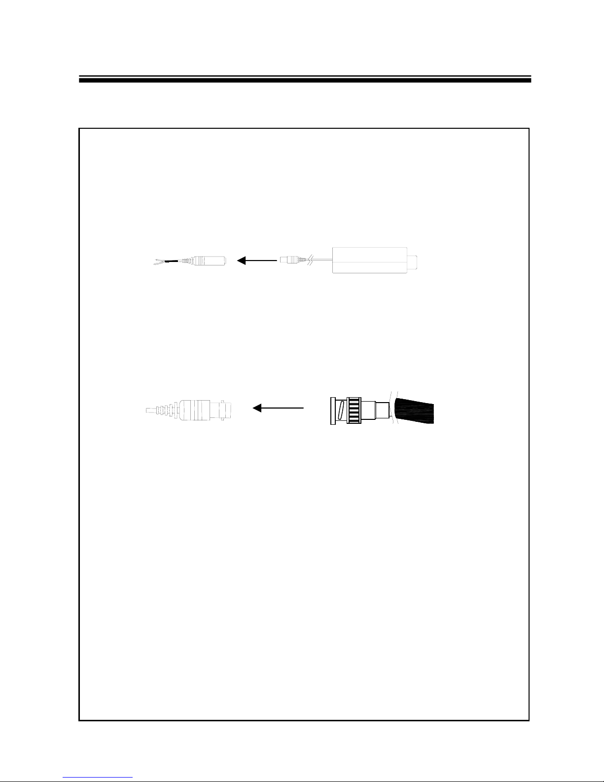
CAMERA INSTALLATION
CONNECT POWER CABLE
1. WHEN USING 12 VOLTS DC (constant voltage 500 mA)
Power Input :RED
Center : (+)
2. CONNECT VIDEO CABLE
-CONNECT BNC CABLE TO THE BNC JACK.
DC 12V Power Supply
6
Page 7
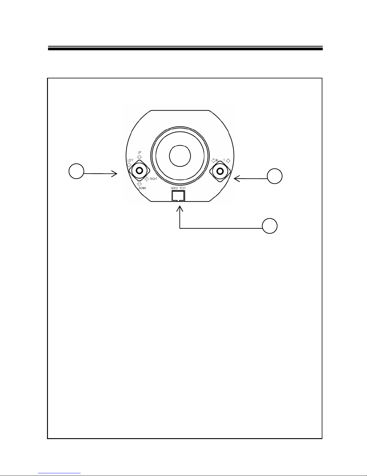
CAMERA INSTALLATION
CONTROL BOARD
2
3
1
1) Video Test Terminal
For second video output
2) OSD (On Screen Display) Joy stick
Press the Joy stick for one second until the OSD menu tree
appears on the screen. Move the Joy Stick up, down, left &
right to control the OSD functions.
3) Lens adjustment (for Zoom) Joy stick
Adjust the Joy stick left or right to control between TELE &
WIDE, Focus is automatically matched without any adjustment.
7
Page 8
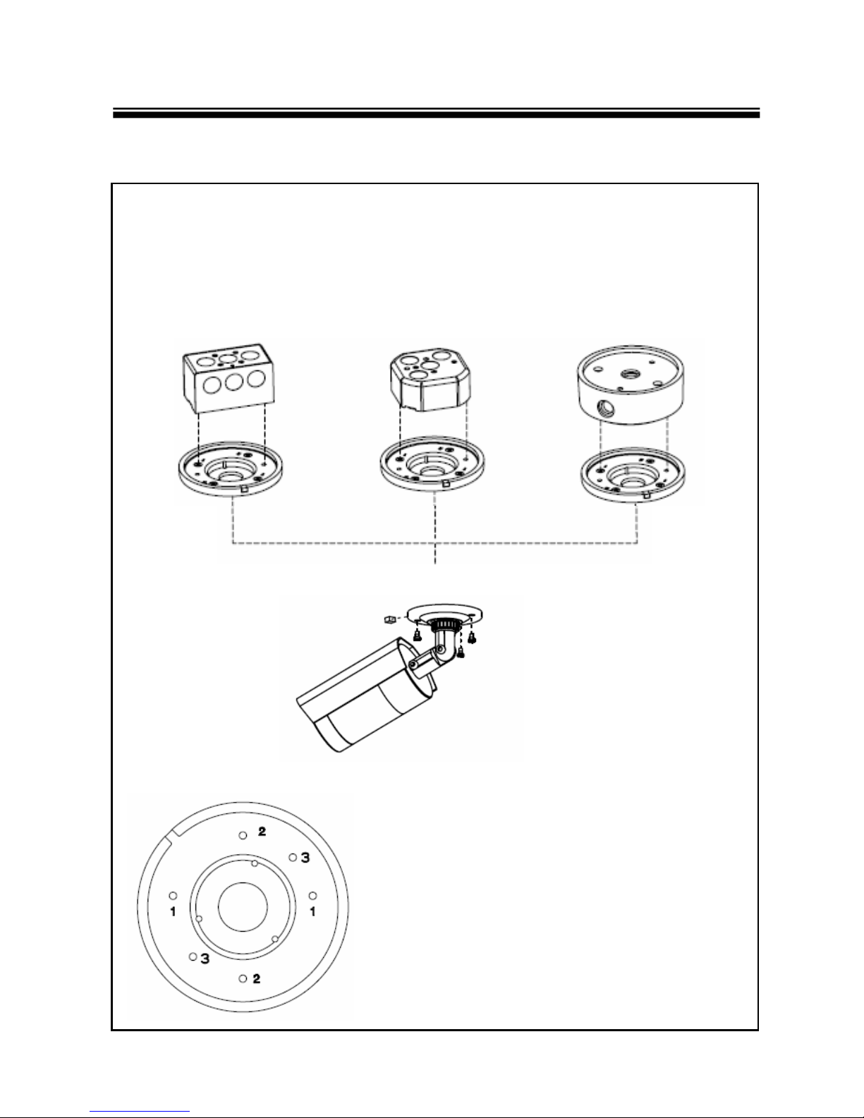
CAMERA INSTALLATION
COMPATIBILITY
CVCTPEXT“A” type Box “B” type Box
CVCTPLATE
[CVCTPLATE Hole Description]
Hole 1 : CVCTPEXT
Hole 2 : Electrical Box “B” type
Hole 3 : Electrical Box “A” type
8
Page 9

CAMERA INSTALLATION
COMPATIBILITY
BCP
( USING
7246WMT
CVCTPEXT
)
CVCTPLATE
BCP (Direct connection )
9
Page 10

FEATURES
FOCUS FREE
With 3.7~10mm FOCUS FREE Auto Iris Motorized Zoom Lens,
Focus can be automatically set up by adjusting zoom position.
No more trips back to the installation to re-focus the camera.
Reduces installation time and service calls.
High Resolution
Horizontal resolution of 550 TV lines is achieved by using a
SONY Super-HAD CCD with 410,000 pixels, and a custom DSP
yielding pictures with a high S/N ratio..
DAY/NIGHT
The camera can show color pictures in all lighting conditions.
Or you can have it automatically switch to a B/W in low light
conditions
S-WDR (Speco WDR)
This is Digital -WDR feature which enables to obtain clear and high
quality pictures even in strong backlight condition.
S-DNR (Speco DNR)
This can remove image noise efficiently showing clean images in
low light conditions.
SLC (Speco BLC)
When the image is in front of strong background lighting,
your camera allows you to get a clear image.
10
Page 11

FEATURES
HLC (High Light Compensation)
This function reverses bright spots in the picture (such as headlights).
It enables the entire system to do a better job of resolving and
displaying grayscale information such as a license plate.
FREEZE
This function freezes the current scene for detailed viewing.
PRIVACY
It also has the ability to mask up to 8 areas of the picture where
Viewing is not desired. Each zone can be independently
programmed via the OSD
OSD
All camera functions are menu driven for easy use.
MIRROR
Picture can be reversed vertically or horizontally.
D-ZOOM
Digital zooming up to 32X.
11
Page 12

OSD MENU TREE
LENS
◆ DC
EXPOSURE
◆ SHUTTER ◆ AGC ◆ SLC ◆ S-WDR ◆ RETURN
WHITE BALANCE
◆ ATW ◆ AWB ◆ AWC-SET ◆ MANUAL ◆ INDOOR ◆ OUTDOOR
DAY / NIGHT
COLOR ◆AUTO ◆EXT ◆B/W
◆
SLC
HLC
S-DNR
◆ ON ◆ OFF
SPECIAL
◆ CAM TITLE ◆ D-EFFECT ◆ MOTION ◆ PRI VACY ◆ RETURN / END
FREEZE
MIRROR
D-ZOOM
GAMMA
NEG.IMAGE
ADJUST
◆ SHARPNESS ◆ BLUE ◆ RED ◆ RETURN / END
RESET
◆ FACTORY ◆ RETURN / END
EXIT
12
Page 13

OSD MENU DETAILS
1. EXPOSURE
[OPTION : SHUTTER / AGC / SLC / S-WDR / RETURN]
- SHUTTER
1/60, FLK, 1/250, 1/500, 1/2000, 1/5000, 1/10000, 1/100000
- AGC (Low / Middle / High)
Adjusts value of AGC gain and increases the GAIN level to brighten the
picture. (noise / distortion may develop)
-SLC
* SLC : Back Light Compensation * HLC : High Light Compensation
- S-WDR (Digital Wide Dynamic Range)
To distinguish a subject in both bright and dark areas.
* INDOOR : Activate S-WDR for Indoor use.
* OUTDOOR : Activate S-WDR for Outdoor use.
2. WHITE BALANCE
[OPTIONS : ATW / AWB / AWC SET / MANUAL / INDOOR / OUTDOOR]
-ATW
Auto Tracking White Balance when the color temp in 1800°K~10500°K.
-AWB
Automatically adjust White Balance to your specific conditions.
- AWC SET
Set while pointing the camera towards a sheet of white paper.
-MANUAL
It allows you to increase or decrease the red or blue factor on screen.
- INDOOR
Select this when the color temp. is 4500°K~ 8500°K.
- OUTDOOR
Select this when the color temp. is 1800°K ~10500°K
13
Page 14

OSD MENU DETAILS
3. DAY / NIGHT
[OPTION : COLOR / BW / AUTO]
- COLOR : Full time color mode
- BW : Full time black & white mode
- AUTO: Automatically detect color or black/white
* DELAY : Set Delay time to switch Color to B/W.
* S-LEVEL : Set Start Level of luminance that you define.
* E-LEVEL : Set End Level of luminance that you define .
*** Only certified technicians should be allowed to this feature.
4. S-DNR
[OPTION : ON / OFF]
- Reduces noise/distortion on the screen.
Increasing the DNR level reduces noise but may introduce video artifacts.
DNR is deactivated if AGC is turned off.
5. SPECIAL - CAM TITLE
[OPTION : ON / OFF]
- Display a name and/or number on the monitor.
14
Page 15

OSD MENU DETAILS
6. SPECIAL – D-EFFECT
[OPTION : FREEZE / MIRROR / D-ZOOM / GAMMA / NEG.IMAGE]
- FREEZE: Freezes the current scene for detailed viewing.
- MIRROR – ROTATE, V-FLIP, MIRROR
- D-ZOOM : Digital zoom of 1 ~32X.
- GAMMA : 0.45 is fixed. Do not adjust it unless certified technician.
- NET. IMAGE : Change colors off like film.
7.SPECIAL - MOTION
[OPTION : ON / OFF]
- To transmit a alert signal when it detects motion of an object on the
screen. 4 Areas can be selectable.
8. SPECIAL - PRIVACY
[OPTION : ON / OFF]
- Mask up to 8 areas of the screen
9. ADJUST
[OPTION : SHARPNESS / BLUE / RED ]
- Adjust sharpness / RED and BLUE characteristics on the picture.
10. RESET
- Restore all factory default settings.
15
Page 16

TROUBLESHOOTING
If you have trouble operating your camera, refer to the following
Problem Solution
Nothing appears on
the screen.
The image on the
screen is dim.
The image on the
screen is dark.
The camera is not
working properly,
and
the surface of the
camera is hot.
● Check that the power cord and line connection
between the camera and monitor are correct
● Check that you have properly connected VIDEO
cable to the camera VIDEO output jack.
● Is the lens stained with dirt? Clean your lens with
soft, clean cloth.
● Set the monitor for the proper co n ditio ns.
● If the camera is exposed to too strong light
change the camera position.
● Adjust the lens’ focus.
● Adjust the contrast feature of the monitor.
● If you have an intermediate device, set the
75Ω/Hi-z properly.
● Check that you have properly connected
the camera to an appropriate power source.
MOTION DETECTION
function is not active.
● Have you set ‘MOTION DET.’ menu to off?
● Have you set ‘MD LEVEL’ to too low?
● Have you set ‘MD AREA’ properly
16
Page 17

TROUBLESHOOTING
Problem Solution
The color of the
picture is not
proper.
The image on the
screen flickers.
● Check that you have properly set the
‘ WHITE BALANCE ’ menu
● Is the camera facing to direct sunlight or fluorescent
lighting? Change the camera position.
17
Page 18

LED PATTERN
3.7-10mm FF lens
18 Mini IR LEDs (80’ Range)
18
Page 19

SPECIFICATIONS
ITEM VLB11SCSFF
Power Source 12VDC Only
Power Consumption 600mA (DC)
Image Sensor 1/3”, SONY SUPER HAD CCD, 410,000 pixels
Total Pixels 811(H) x 508(V) , 1/3”CCD
Effective Pixels 768(H) x 494(V) , 1/3”CCD
LENS TYPE
Maximum Aperture Ratio 1 : 1.3 ~2.0
Scanning System 2 : 1 Interlaced 525 Lines / 60 Fields / 30 Frames
Synchronization Internal
Video Output 1.0V [p-p] Composite, 75Ω
Resolution 550 TV Line
Gain Control AGC-L, AGC-M, AGC-H, OFF selectable
Electric Shutter Speed 1/60 ~ 1/200,000 sec
DAY / NIGHT COLOR / AUTO / BW
COLOR TEMP (White Balance) ATW / AWB / AWC-SET / MANUAL / INDOOR / OUTDOOR
Min. Illumination 0.3 LUX (F 1.2), 0.00LUX (LED ON)
S/N ( Y signal) 52dB (Weight On)
SPECO DNR ON / OFF
Focus Free Lens 3.7~10mm
Motion Detection ON / OFF (4 Programmable Zone)
On Screen Display ( O.S.D ) Built - in
PRIVACY Function ON / OFF (8 Programmable Zone)
Operational Temperature -29℃ ~ +50℃ ( - 20℉ ~122℉)
Operational Humidity 30% ~90% RH
19
Page 20

* FRONT VIEW
DIMENSIONS
* SIDE VIEW
20
Page 21

WARRANTY
21
Page 22

MEMO
Page 23

MEMO
Page 24

This manual is based on the date as shown in the right and specifications are subject
to Change without notice for quality improvement.
200 New Highway
Amityville, NY 11701
631-957-8700
www.specotech.com
VER. 090706
 Loading...