

Page 1

Aug. 2010, Rev.6
Page 2
User Guide Rev 1.0
Page 2
Contents
Notice
1. Introduction
1.1. Important Notice
2. Installation of Speco-NVR
3. Screen
3.1. Functional Buttons and Indicators
3.2. Video Display Window
3.3. Quick Control Pop-Up Menu
3.4. Summary of Buttons
4. First Connection to Live Video
5. Detailed Description
5.1. Screen Layout
5.2. IP Set Up
5.3. Hard Disk Configuration
5.4. Alarm Recording
5.5. Recording Schedule
5.6. Playback
5.7. Live Connection and Recording
5.8. Bidirectional Audio
5.9. Still Image Capture
5.10. Rotating the Video
5.11. Remote Management
5.12. Sensor and Motion Alarm Indication
5.13. Remote Relay On/Off
5.14. Video and Audio Adjustment
5.15. PTZ and Camera Control
5.16. Video crop
5.17. Digital PTZ
6. Event Log Management
6.1. Event Log Window
7. Remote Video Storage (RVS) Management
7.1. RVS Control of IP Camera or Video Server
8. Virtual System Controller
9. Screen Lock & Unlock
10. E-Map
10.1. E-Map (GUI)
10.2. Addition and Deletion of Map Image
10.3. Placing MAP ICON
10.4. Placing Camera ICON
10.5. Locking/Unlocking the locations of the ICONS
10.6. MAP and Camera Status Indication
10.7. Connection to the Camera for Live View
10.8. Event Display
10.9. Relocating the Functional Windows
Appendix
A. Recommended CPU/Graphics Card Specifications
B. HDD Space Calculation
C. Converting ICF file to AVI file
Page 3
User Guide Rev 1.0
Page 3
Notice – Must be read before you start Speco-NVR!!
• Dedicated HDD is needed for the recording of the video data.
– Add HDD solely for recording the data or make a partition on the HDD
– The HDD or the partition for the recording should not contain data other than the data recorded
by Speco-NVR.
• Avoid following conditions to prevent System Crash or Reboot
– Automatic Windows Upgrade Setting
• If you specify the time for the automatic upgrade of your windows operating system, the
automatic upgrade can cause reboot or system halt.
• Automatic upgrade of the windows operating system is not recommended.
– Multi monitor device driver for the NVIDIA video chip set can cause reboot or system halt. We
do not recommend to use video cards using NVIDIA chip sets.
• Recommended settings of the frame rate and data bit rate.
– D1 size video : set the frame rates less than 15FPS.
– CIF size video : make sure to set the summation of the bit rates from all video channels less
than 50Mbps.
Page 4

User Guide Rev 1.0
Page 4
1. Introduction
• Speco-NVR is a PC application program package targeted for use on a centralized
real time video monitoring and recording system based on network cameras, video
servers.
• Speco-NVR needs a high performance PC. It is recommended to install Speco-NVR
on a highly reliable hardware platform such as workstation. And Windows XP is
recommended for the OS.
– Speco-NVR shows the maximum stability and the performance when the PC is running no other
application programs.
– Basic screen of Speco-NVR includes up to 16 videos.
• Speco-NVR supports all network cameras supplied by Speco.
• The key features of Speco-NVR are :
– Supports up to 64 channels
– Live monitoring, Recording, Remote management of the network cameras.
– Various recording modes : Schedule, Manual, Alarm, Motion triggered
– A separate playback screen that can handle up to 16 simultaneous playback without
interrupting real time monitoring.
– Separate Event Log management
– Integrated Pan/Tilt/Zoom control.
Page 5
User Guide Rev 1.0
Page 5
1. Introduction
• The basic display screen of Speco-NVR consists of up to 16 video windows. Up to 4
basic display screens can be launched simultaneously to support up to 64 channels.
• These screens can be shown on a single large screen or can be displayed on multiple display
monitors. When using multiple monitors, make sure to install sufficient graphic card on your PC.
Page 6

User Guide Rev 1.0
Page 6
1.1. Introduction – Important Notice
• Time reference of Speco-NVR
– Speco-NVR includes the features that need time reference. Speco-NVR refers to the time set
on the PC for the operation. It is very important to keep the clock of the PC precise.
– The time which is displayed beneath each screen in white color for real time connection is the
time information sent from the network camera.
• Do not change the parameters related with network configuration while the SpecoNVR has a video connection with corresponding device.
• Do not run application programs other than Speco-NVR on the same PC.
This can cause instability and performance degradation of the Speco-NVR.
Page 7
User Guide Rev 1.0
Page 7
1.1. Introduction – for Windows Vista
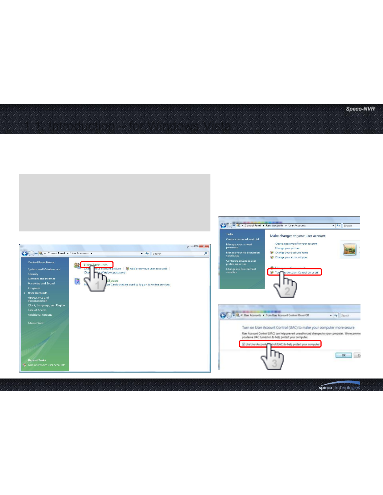
Windows Vista and Windows 7 users need to configure UAC (User Access Control) and Privilege
Level for proper recording and still video capture in Speco-NVR and Web Viewer. Follow through the
details in this document to ensure the setting.
<Windows Vista>
1. UAC (User Access Control) configuration
1) Double-click “User Accounts” in control panel
2) Double-click “Turn User Account Control on or off”
3) Uncheck “Use UAC to help protect your computer”
3
2
1
Page 8
User Guide Rev 1.0
Page 8
1.1. Introduction – for Windows Vista
<Windows Vista>
2. Privilege Level Control
1) Select “Speco-NVR” icon on the desktop
2) Click right mouse button and select “Properties”
3) Check “Privilege Level” in “Compatibility” tab
3
2
1
Page 9

User Guide Rev 1.0
Page 9
1.1. Introduction – for Windows 7
<Windows 7>
1. UAC (User Access Control) configuration
1) Double-click “User Accounts” in control panel
2) Double-click “Change User Account Control setting”
3) Set to “Never notify”
3
2
1
Page 10

User Guide Rev 1.0
Page 10
1.1. Introduction – for Windows 7
<Windows 7>
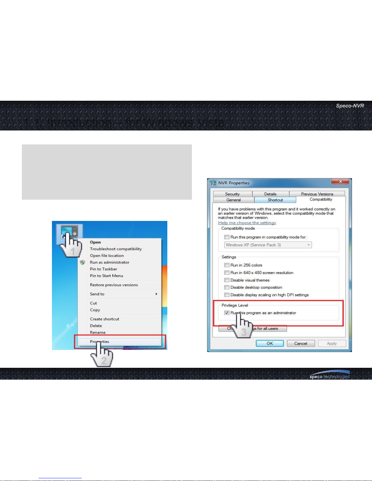
2. Privilege Level Control
1) Select “Speco-NVR” icon on the desktop
2) Click right mouse button and select “Properties”
3) Check “Privilege Level” in “Compatibility” tab
1
2
3
Page 11
User Guide Rev 1.0
Page 11
2. Installation of Speco-NVR
• Install “Speco-NVR” S/W from the material CD.
• Program installation will continue automatically and after the installation a
launcher icon will be created on your desktop.
• To play the recorded video file in Event Log Window, “icfPlayer” program will be
installed automatically upon the installation of Speco-NVR.
• For the sake of stability and improved performance, Speco-NVR is designed to
use dedicated HDDs for recording the AV data.
• Never use the HDD assigned for recording the AV data in Speco-NVR to save
other files or programs.
Speco assumes no responsibility caused by failure of observing this restriction.
Page 12

User Guide Rev 1.0
Page 12
3.1. Screen – Functional Buttons and Indicators
Clone Window
ON/OFF Button
Change Channels
Displayed
Screen
Configuration
Screen
Lock
Channel Status
Indicator
Remote Relay
On / Off
Display
Ratio Swap
Full Screen
Display
Display Unit (DU).
The smallest DU is called MDU (Minimum
display Unit). This can be called as Channel
when connection information is set up
Focus
Control
Pan / Tilt
Control
Zoom
Control
Page 13

User Guide Rev 1.0
Page 13
3.2. Screen – Functional Buttons and Indicators
Magnify Highlighted
Channel
Live Connection
Control
Manual Recording
Control
HDD Usage
Indicator
Bidirectional
Audio ON/OFF
RVS
Control
Virtual
Controller for
PTZ Camera
E-map
Centering
Move to
Preset Position
PTZ Parameter
Set-up
Move to
PTZ Home
Audio/Video
Control
Sensor and
Motion Indicators
for Each of 16
Channels
Connect to
Admin Page
Rotate Video
By 180 Degree
Still Video
Capture
Close NVR
Quad Mode Display Including
Highlighted Channel
Page 14
User Guide Rev 1.0
Page 14
3.2. Screen – Video Display Window
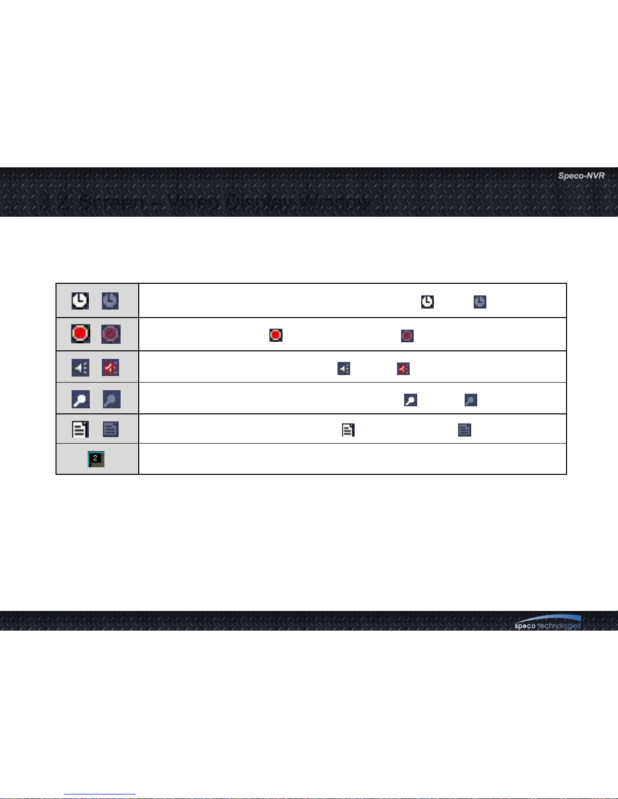
• Video display window is an area that displays video sent from the locations being monitored. The window can be
divided into 16 sub-screens called Display Unit (DU). Each DU has video display area and status indicator area.
• Channel Status Indicator
• Messages
– When there is no live connection, the message area indicates whether connection information is
programmed or not (Assigned / Not Assigned).
– When the channel is in live connection, the message area displays time and channel description. The time
displayed in the message area is the time set on the device sending the video. Remember that this time
can be different from the time set on the PC.
– The size of the video is displayed in QCIF to UXGA.
Indicates the presence of recording schedule. YES ( ), NO ( )
Recording in progress ( ) / Recording stopped( )
Indicates whether audio is enabled ( ) or Not ( ).
Indicates whether bidirectional audio is enabled ( ) or Not ( ).
Indicates the presence of new event( ) or no new event ( )
Indicates number of connected users
Page 15
User Guide Rev 1.0
Page 15
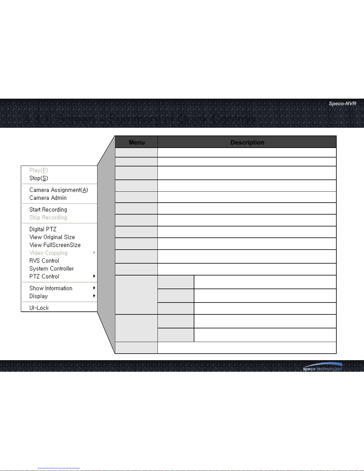
3.3. Screen - Quick Control Pop-Up Menu
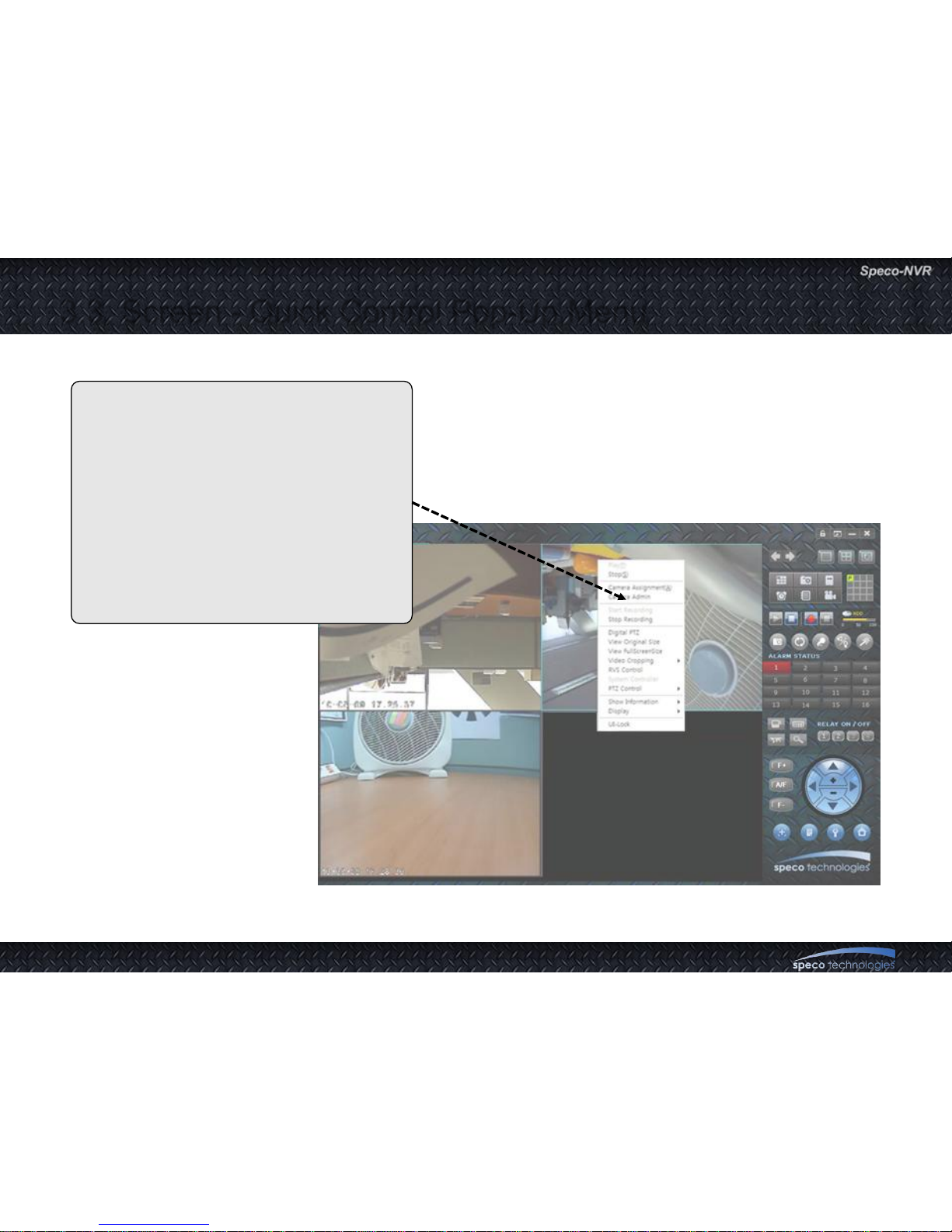
• Locate the cursor on each DU and
press right mouse button to enable
pop-up menu.
• Simple controls indicated on the right
can be initiated for each channel.
• Move the cursor to desired operation
and press left mouse button to start
the operation.
Page 16
User Guide Rev 1.0
Page 16
3.3.1. Screen – Summary of Quick Controls
Menu Description
Play Make connection with selected network camera.
Stop Disconnect selected network camera.
Camera
Assignment
Modify information of selected network camera.
Camera Admin Run Administration Tools of selected network camera.
Start Recording Start recording from selected Display Unit.
Stop Recording Stop recording of selected Display Unit.
Digital PTZ Toggle digital PTZ function in selected Display Unit.
Video Cropping Select region size of video cropping.
RVS Control Run RVS control.
System
Controller
Run virtual keyboard controller.
PTZ Control Run additional PTZ actions.
Show
Information
Session
Count
Display number of connections that connected with network
camera.
Packet Loss
Ratio
Display packet loss ratio of network connection between PC
with network camera.
Frame Rate Display average frame rate per second of network camera.
Display
Original
Ratio
Toggle the display ratio as original and fit.
Show Status
Bar
Toggle the display status bar on and off
UI-Lock Lock up NVR control interface to prevent unsecured access
Page 17
User Guide Rev 1.0
Page 17
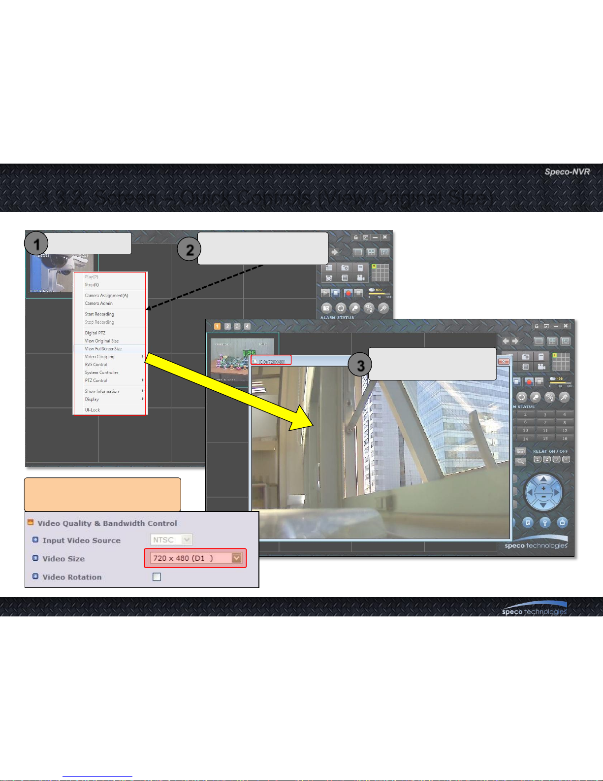
3.3.2. Screen – Quick Controls (View Original Size)
Select a channel
1
Select the View Original
Size from pop-up menu.
2
A new window will pop up
with original video size
3
The display window size follows
setting in Administration tools
Page 18
User Guide Rev 1.0
Page 18
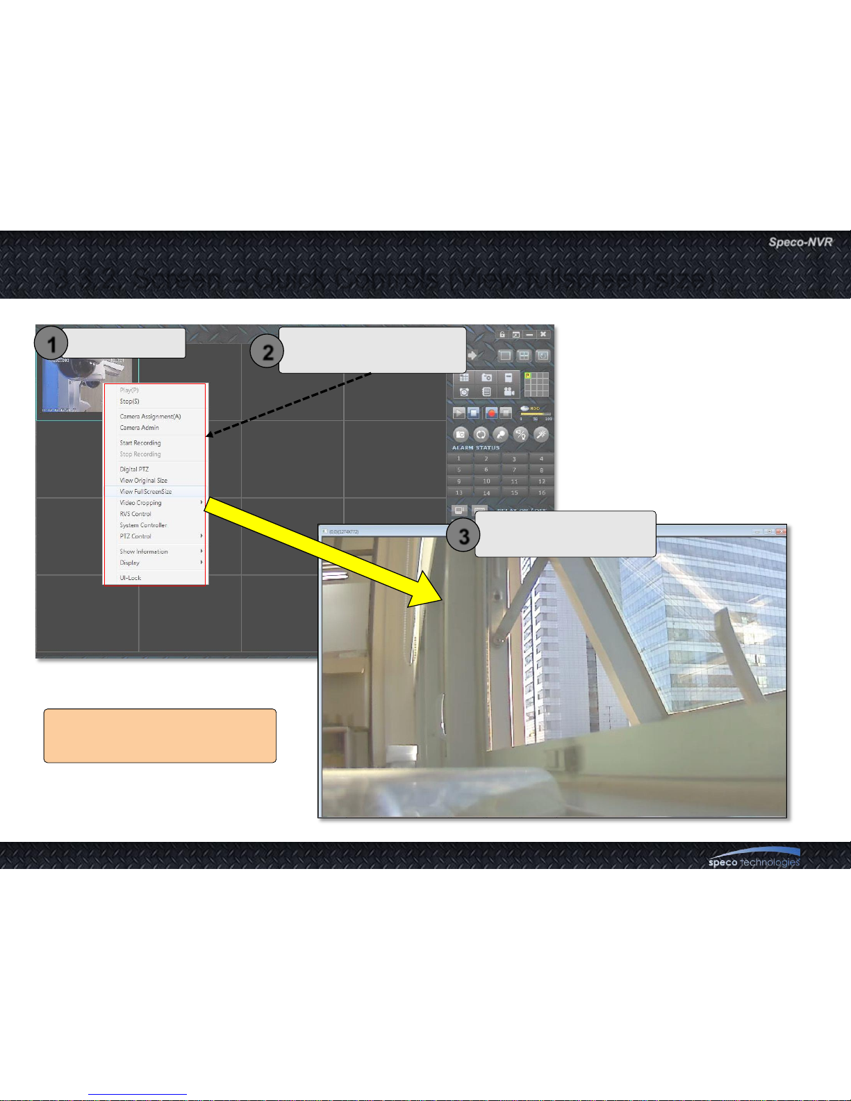
3.3.2. Screen – Quick Controls (View fullscreen size)
Select a channel
1
Select the View Fullscreen
Size from pop-up menu.
2
A new window will pop up
with fullscreen video size
3
The display window size follows
video resolution setting of screen
Page 19
User Guide Rev 1.0
Page 19
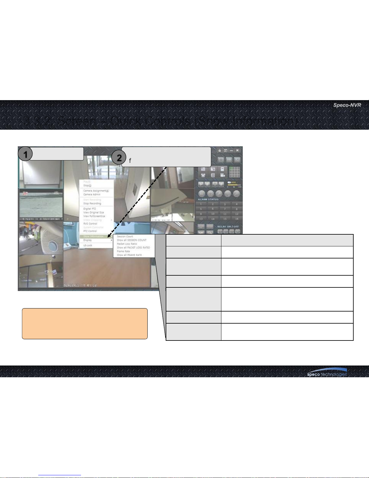
MENU Description
Session Count Display how many connection made with camera.
Show all
SESSION COUNT
Turn on „session count‟ on all channel in screen.
Packet Loss Ratio Display the ratio of network packet loss.
Show all
PACKET LOSS
RATIO
Turn on „packet loss ratio‟ on all channels in the
screen.
Frame Rate Display the average frame rate per second.
Show all
FRAME RATIO
Turn on „frame ratio‟ on all channels in the screen.
3.3.2. Screen – Quick Controls (Show Information)
Select a channel
1
Select the Show Information
from pop-up menu.
2
The feature display the informations that
related with video streaming from
connected network camera
Page 20

User Guide Rev 1.0
Page 20
MENU Desciption
Original ratio
The video image in selected DU keep original
display ratio. The video image will not fit to DU size.
Show all
ORIGINAL RATIO
Turn on „original ratio‟ on all channels in screen.
Show status bar Display status bar on bottom of DU.
Show all
STATUS BAR
Turn on „status bar‟ on all channels in screen.
3.3.2. Screen – Quick Controls (Display)
Select a channel
1
Select the Display
from pop-up menu.
2
The feature display the informations that
related with video display from connected
network camera
Page 21
User Guide Rev 1.0
Page 21
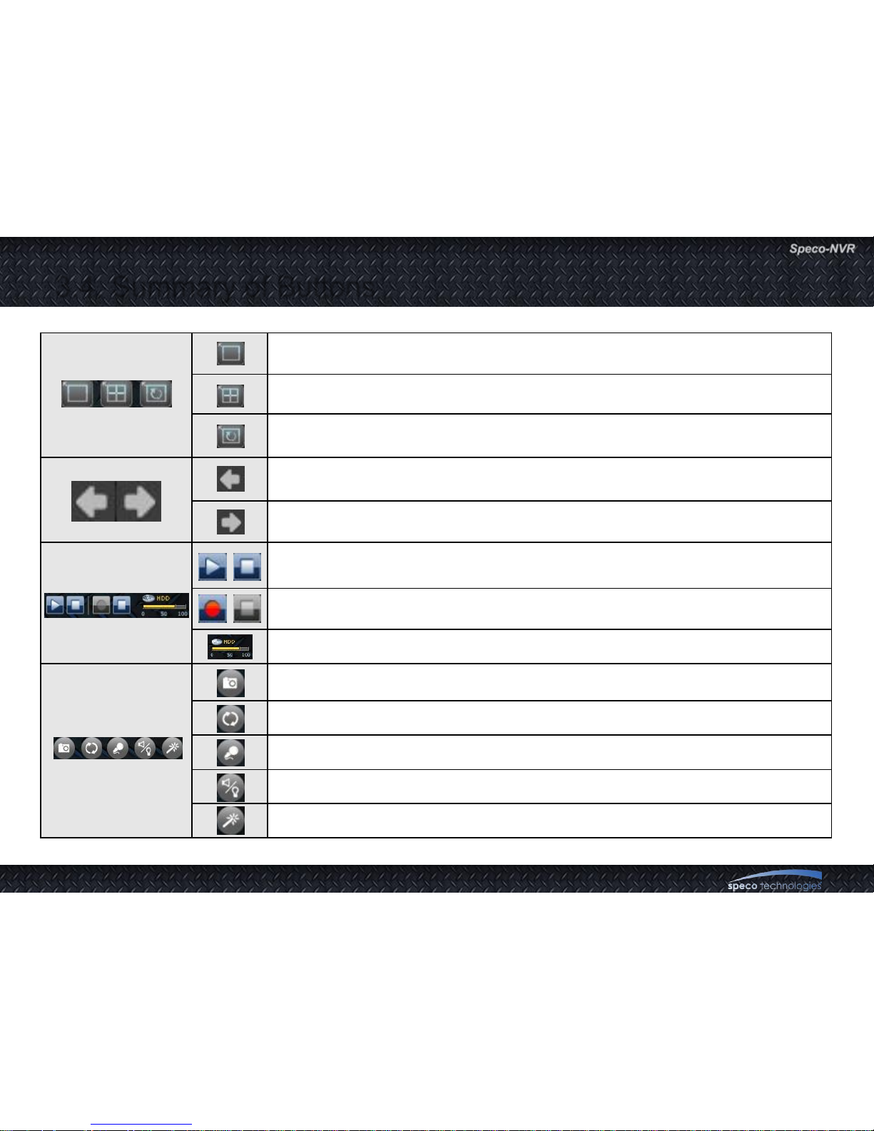
3.4. Summary of Buttons
Magnify the highlighted channel to occupy entire display area.
Display the highlighted channel and the following 3 channels in 2 x 2 mode.
Return to original screen layout.
Display former 1 or 4 channels in the display area following the settings of the display.
Display next 1 or 4 channels in the display area following the settings of the display.
Connect (and view) or disconnect to the entire channels which are configured.
Start or stop recording of A/V data from all connected channels.
Show the percentage of the HDD usage.
Capture a still video of the highlighted channel.
Flip the video of the highlighted channel.
Enable/Disable bidirectional audio communication for the highlighted channel.
A control window for the audio and video adjustment is launched.
Connect to the admin page of the highlighted channel.
Page 22
User Guide Rev 1.0
Page 22
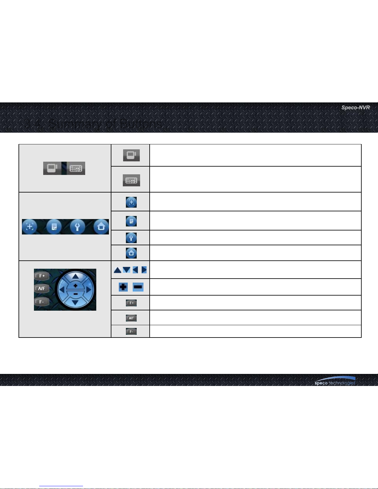
If the highlighted channel product have internal storage, a new window for
the control of the HDD is launched.
Virtual controller for controlling PTZ camera is launched. This is
applicable only for OPTZ36XI, OPTZ36XO.
When this button is activated, the camera center is moved to the point
where the mouse click is made.
Displays preset positions. If one of the list is selected, the camera moves
to selected preset position.
A new control window for setting various PTZ parameters is launched.
Move the camera to home position.
* These controls are available when
the channel is equipped with proper
PTZ features.
Move the camera to UP/DOWN/LEFT/RIGHT.
Zoom In or Zoom Out.
Move the focus to near position.
Automatic focus adjustment
Move the focus to far position.
3.4. Summary of Buttons
Page 23
User Guide Rev 1.0
Page 23
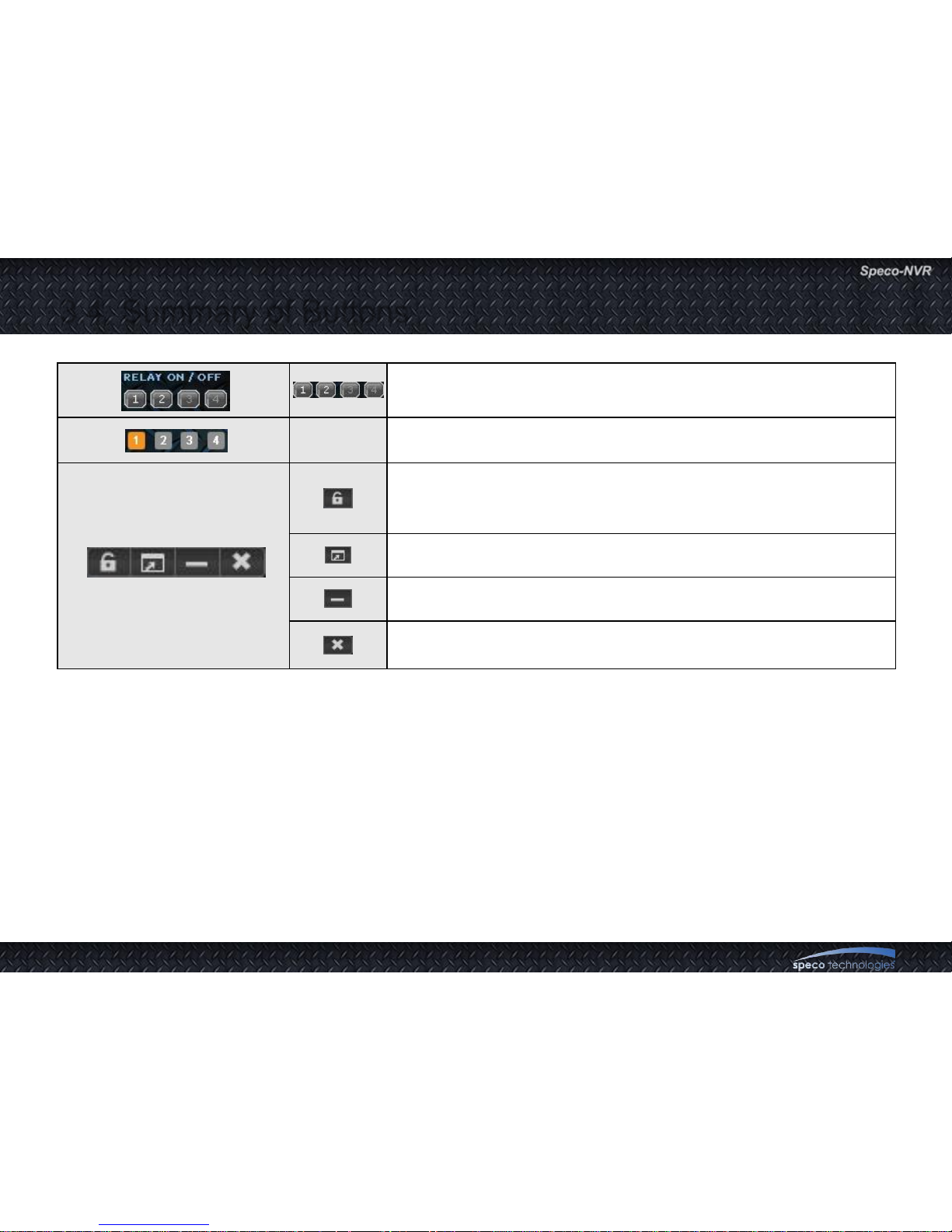
On/Off the relay of the highlighted channel. In the text area name of
the relay is shown.
On/Off control of clone windows 2,3,4.
Screen Lock. When the screen is locked all the controls except for the
display will be locked.
Enter the ID and password to unlock the screen.
Enlarge the screen to fill the monitor.
Minimize Speco-NVR.
Terminate the program. ID and password are required to terminate the
program.
3.4. Summary of Buttons
Page 24
User Guide Rev 1.0
Page 24
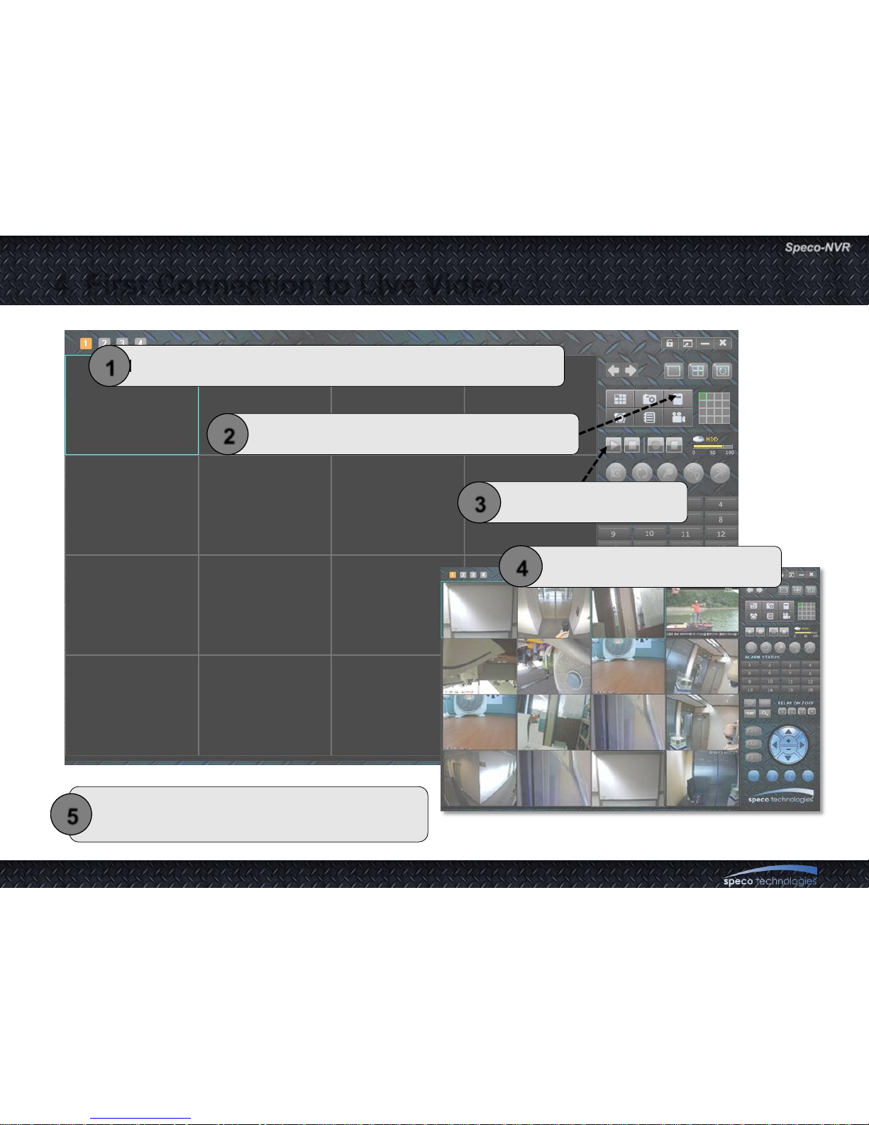
4. First Connection to Live Video
Install Speco-NVR and connect your PC to the network.
1
Set-up IP information for the connection.
2
Click on Play Button.
3
For further information, please refer to the
remaining part of the manual.
5
Example of live connection.
4
Page 25
User Guide Rev 1.0
Page 25
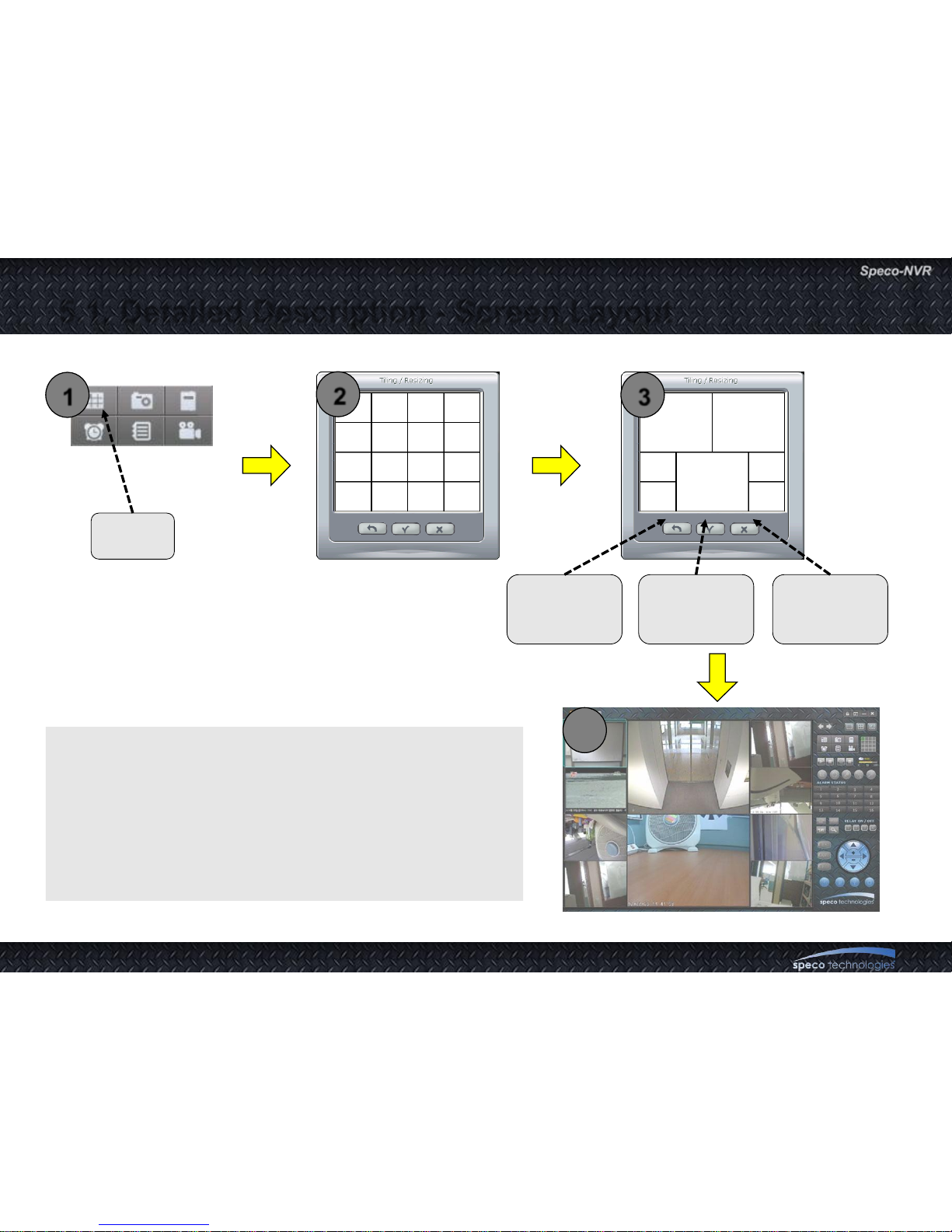
5.1. Detailed Description - Screen Layout
1. Combine adjacent MDUs from 4 x 4 screen to create larger
Display Area (DU).
2. Click on the corresponding MDU and move the cursor in
diagonal direction while the mouse button is pressed.
3. Release the mouse button when desired number of MDUs
are merged to create a new Display Unit (DU).
CLICK
Go back to
initial layout.
(4x4)
Neglect the
modification
Apply the
modification
<Example of a screen having 7 DUs>
1
2
3
4
Page 26
User Guide Rev 1.0
Page 26
5.1. Detailed Description - Screen Layout
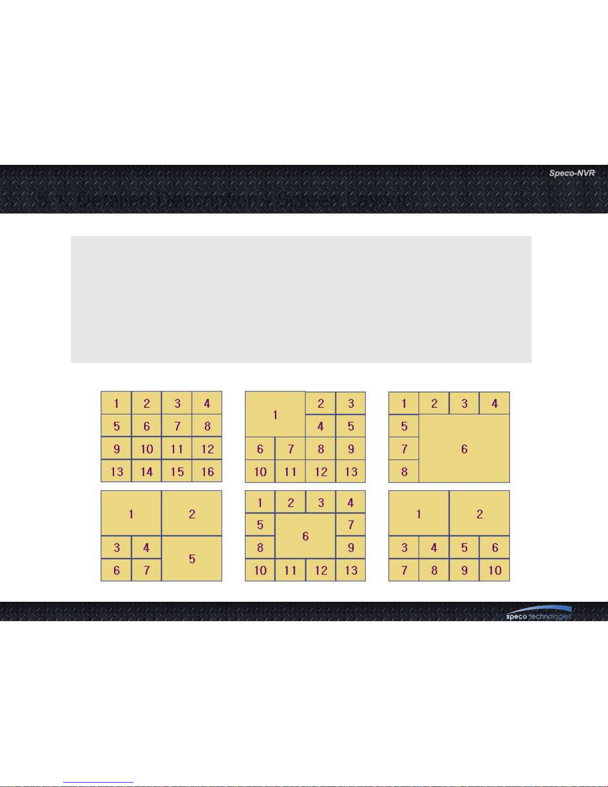
Assigning sequence numbers to the DUs.
To assign set up parameters to the DUs for the new layout, each DU is assigned with
a number following the rule below.
DU at the top of the leftmost location has number 1.
Number is increased as we move to the right and to the bottom.
Reference position for the location is the top-left corner of each DU.
Page 27
User Guide Rev 1.0
Page 27
5.2. Detailed Description – IP Set Up
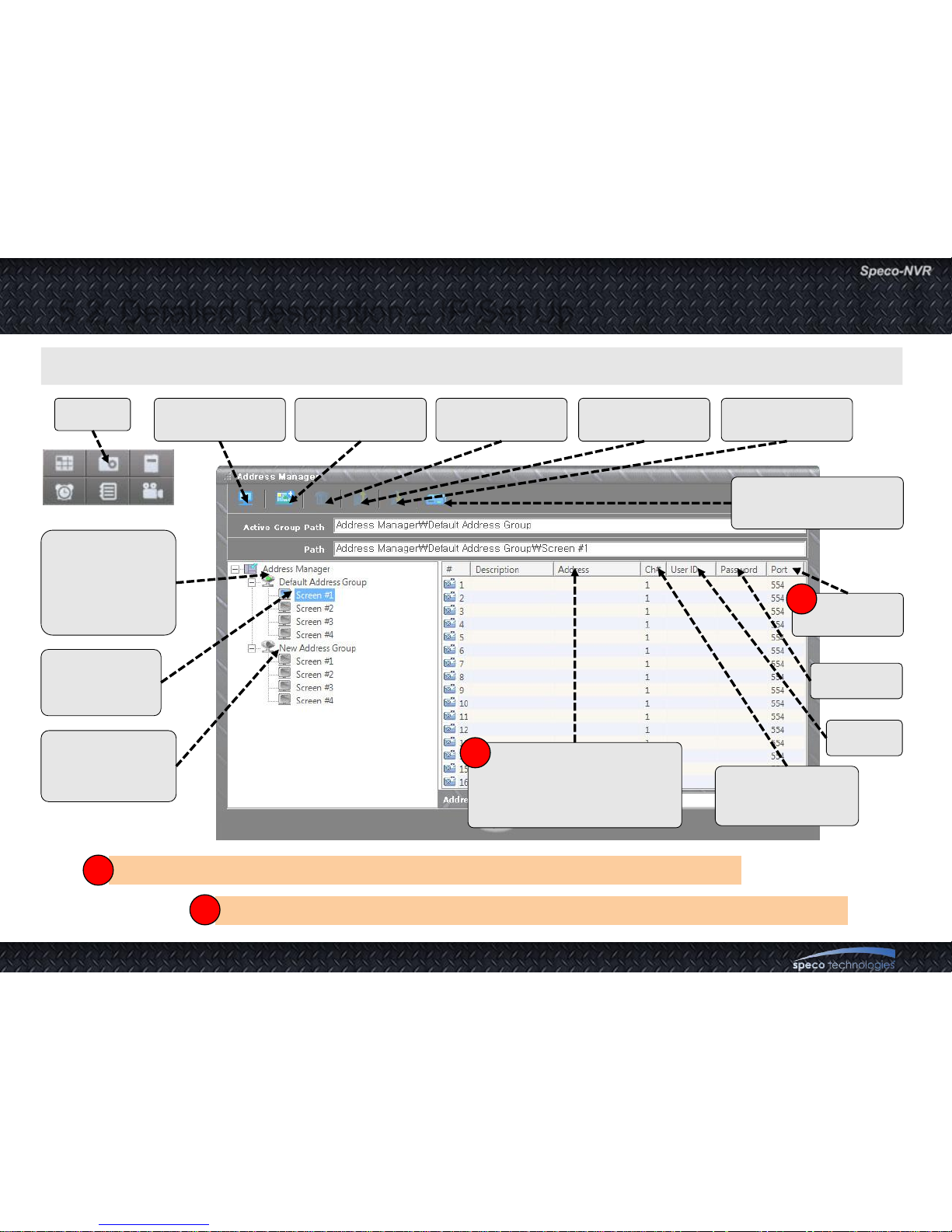
Input parameters needed for the connection.
IP can be replaced with host name when the device is registered with the DDNS server.
!
Find Active
Address Group
Create a new
Address Group
Delete selected
Address Group
Save selected
Address Group
Open Stored
Address Group
Multi-channel
product set up button
Address Group
(Address group
in Green color
is the selected
address group)
Screen within
an Address
Group
Address Group
which are not in
use presently.
IP Address (In case of
using web port other than
80, insert web port as “[IP
address:PORT NUM.]”.)
Channel Number
for multi channel
device
User ID
Password
RTSP
Port number
CLICK
!!
!
Input RTSP port number when port forwarding is enabled using IP sharing device
!!
Page 28
User Guide Rev 1.0
Page 28
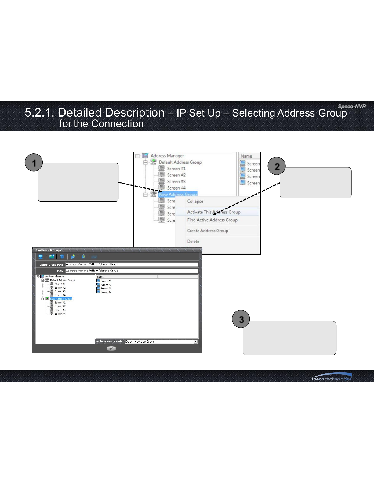
Locate the cursor on top
of the corresponding
Address Group and press
right mouse button.
Select “Activate This
Address Group” from
the Pop-up menu.
1
2
Go back to the main screen.
Stop all connection and
connect again.
3
Page 29
User Guide Rev 1.0
Page 29
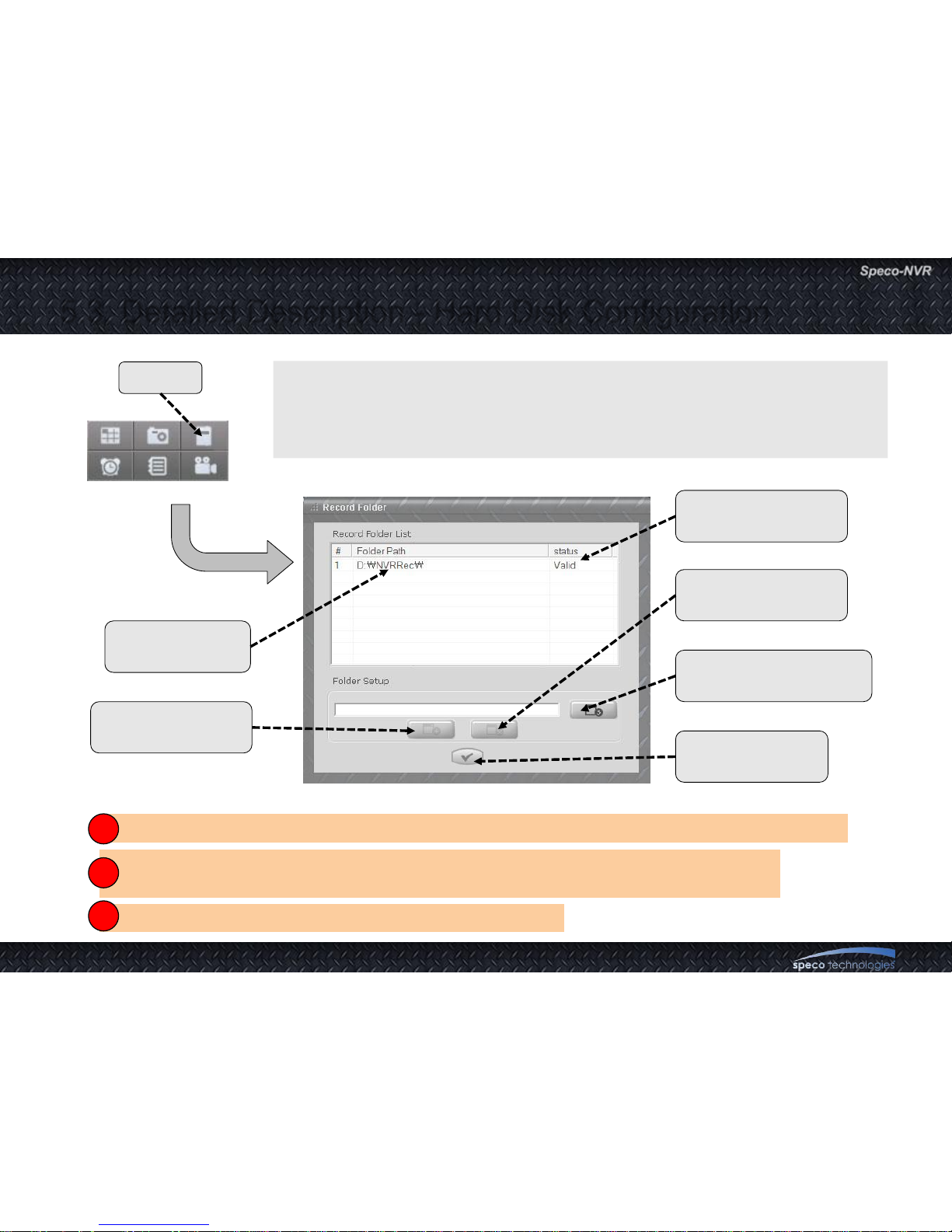
5.3. Detailed Description - Hard Disk Configuration
• Assign or de-assign HDD to store video.
• The overwriting function is enabled as default, it will work when HDDs
are full. NVR will delete records from the oldest date.
Never use the HDD assigned for recording the AV data in Speco-NVR to store other files.
Speco assumes no responsibility caused by failure of observing the restriction.
1 HDD is equivalent to one folder. And the total capacity of the HDD is assigned as the size of folder.
Do not use the HDD having OS as the HDD for recording.
!
!!
!!!
Show the list
of the HDDs
Register the
recording HDD.
Erase registered
recording HDD.
Search for or create
a recording folder.
Finish the
configuration
CLICK
Status of the
registered HDDs
Page 30
User Guide Rev 1.0
Page 30
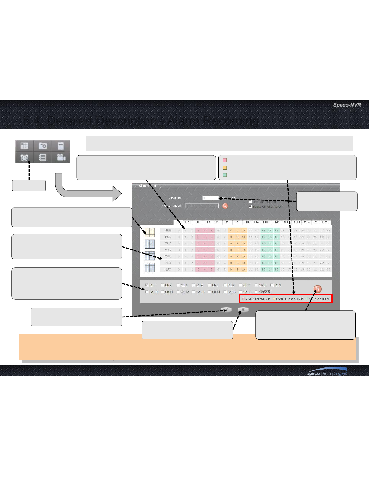
5.4. Detailed Description - Alarm Recording
Caution :
For addition or changing of the schedule, make sure to select channels before the operation. Only the changes made
after the channel selection are applied.
Set alarm schedule for each channel in 1 hour resolution.
The selection is applied for single channel.
The selection is applied for multiple channels.
The selection is applied for all channels.
Click on corresponding time to control recording.
Selected time zone is indicated as a box having
different background color.
Click on the desired screen.
Selected screen is shown in yellow color.
Place the cursor on top of a time slot.
The tool tip will show the channels
having schedules on the time slot.
Select desired channel.
You can select multiple channels.
Only the schedules entered after the
channel selection are applied.
Apply the change and return
to the previous menu.
Neglect the change and return
to the previous menu.
Erase the programmed schedule.
You must select channels before
erasing the schedule.
CLICK
Set the duration for
alarm recording.
Page 31
User Guide Rev 1.0
Page 31
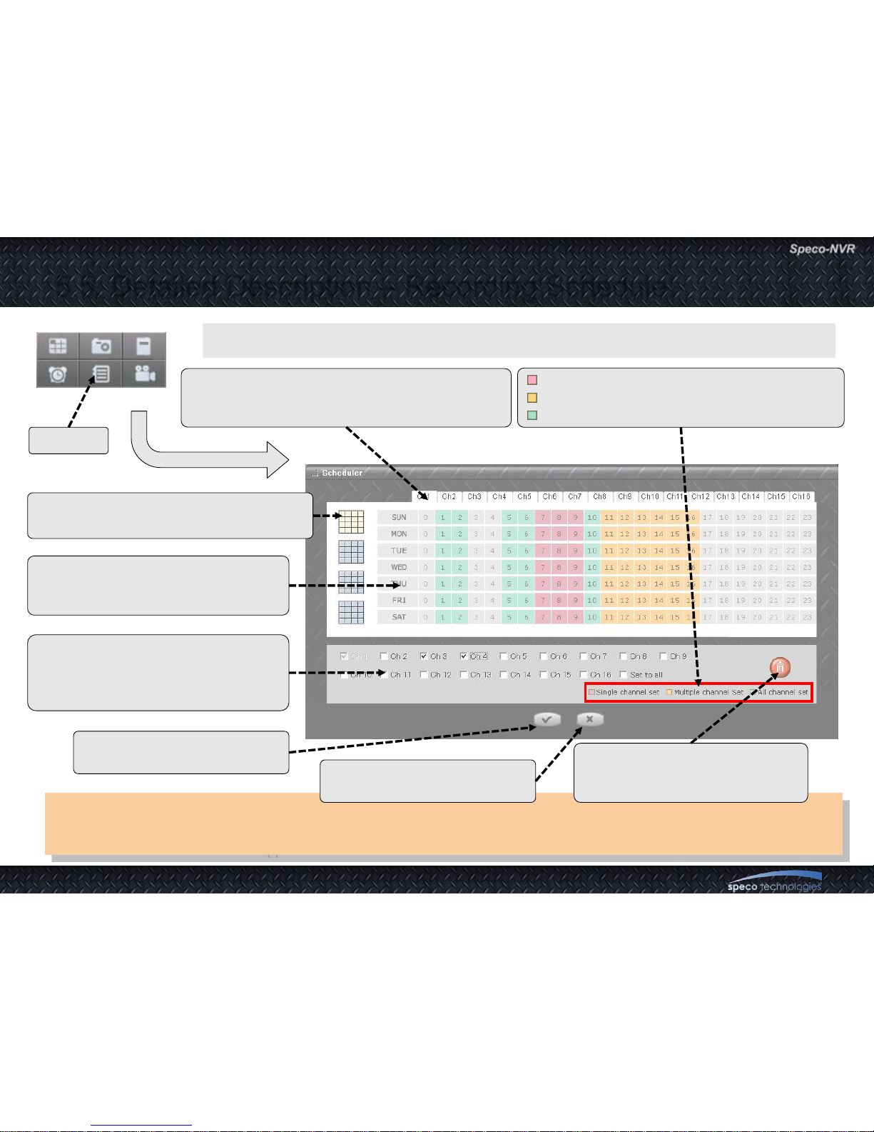
5.5. Detailed Description – Recording Schedule
Caution :
For addition or changing of the schedule, make sure to select channels before the operation. Only the changes made
after the channel selection are applied.
Set recording schedule for each channel in 1 hour resolution.
The selection is applied for single channel.
The selection is applied for multiple channels.
The selection is applied for all channels.
Click on corresponding time to control recording.
Selected time zone is indicated as a box having
different background color.
Click on the desired screen.
Selected screen is shown in yellow color.
Place the cursor on top of a time slot.
The tool tip will show the channels
having schedules on the time slot.
Select desired channel.
You can select multiple channels.
Only the schedules entered after the
channel selection are applied.
Apply the change and return
to the previous menu.
Neglect the change and return
to the previous menu.
Erase the programmed schedule.
You must select channels before
erasing the schedule.
CLICK
Page 32
User Guide Rev 1.0
Page 32
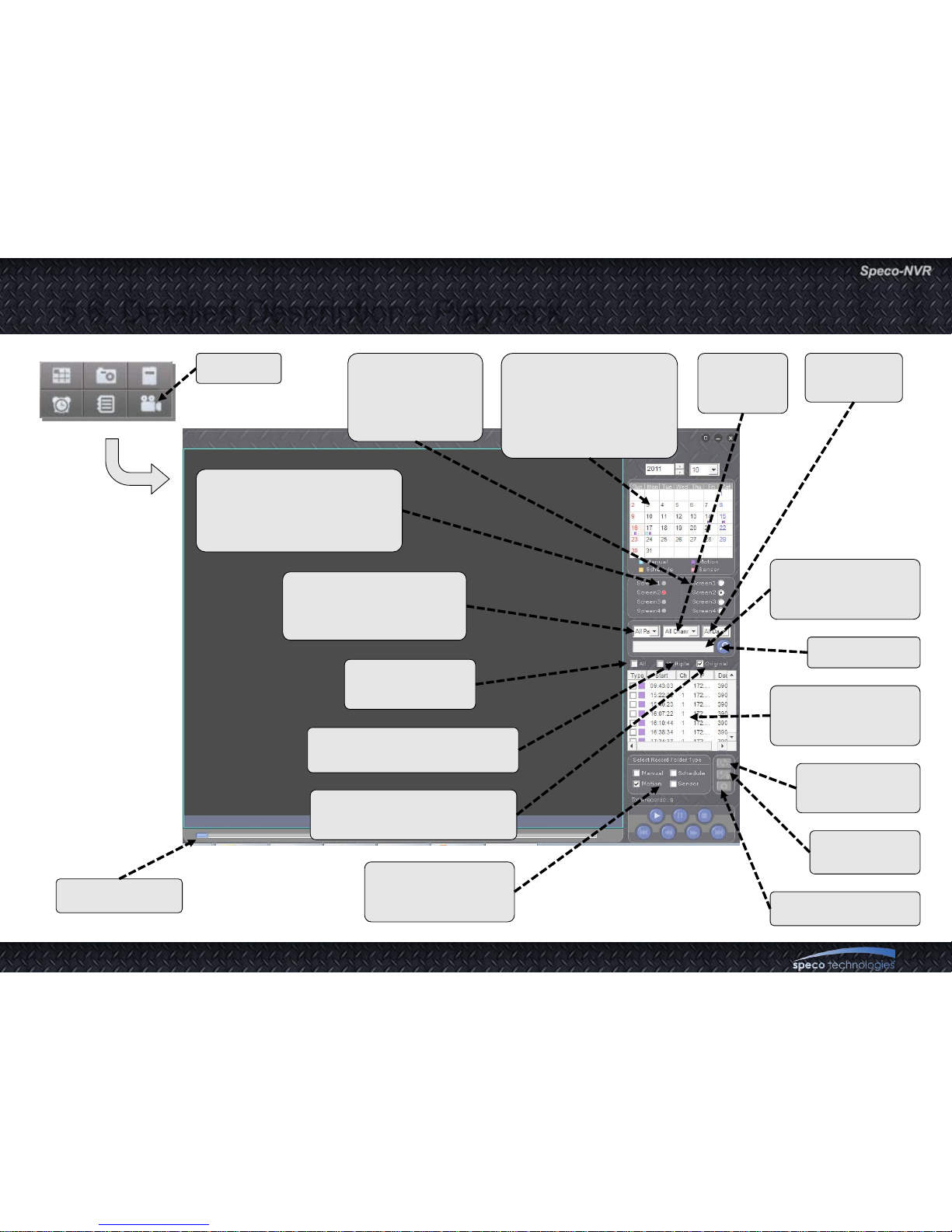
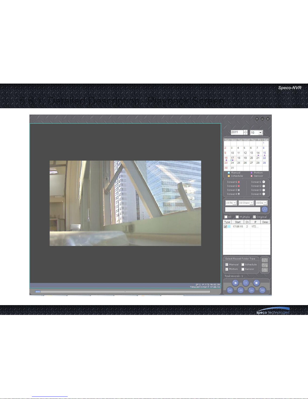
5.6. Detailed Description - Playback
If there is recorded file on
the date for the selected
screen page, this circle is
shown in red color.
Search condition input
field when data type is
other than “All Data”.
Check to select
all in the list.
Check to enable playback
of multiple channels
Check during playback to
display in original size.
Mark this
button to select
corresponding
page.
If there is recorded
file on the date,
types of the video
files are summarized
in 4 different colors.
Channel
Selection
filter.
Data Type
filter.
Filter for selecting
search method
Start Search
Search List.
Check the box at
the left to select.
Rotate video
by 180 degree
Capture still video
Record file type
filter
Adjust audio
and video
Time indicator
CLICK
Page 33
User Guide Rev 1.0
Page 33
5.6.1. Detailed Description - Playback Screen
Page 34
User Guide Rev 1.0
Page 34
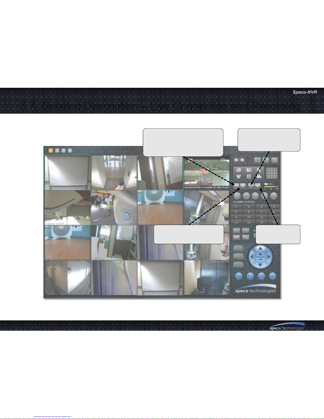
5.7. Detailed Description – Live Connection and Recording
Click for live connection to all
channels. Camera information
are programmed through IP
assignment.
Click to stop all
recording.
Click to record video
and audio from all live
connection.
Click to disconnect entire
live connection.
Page 35
User Guide Rev 1.0
Page 35
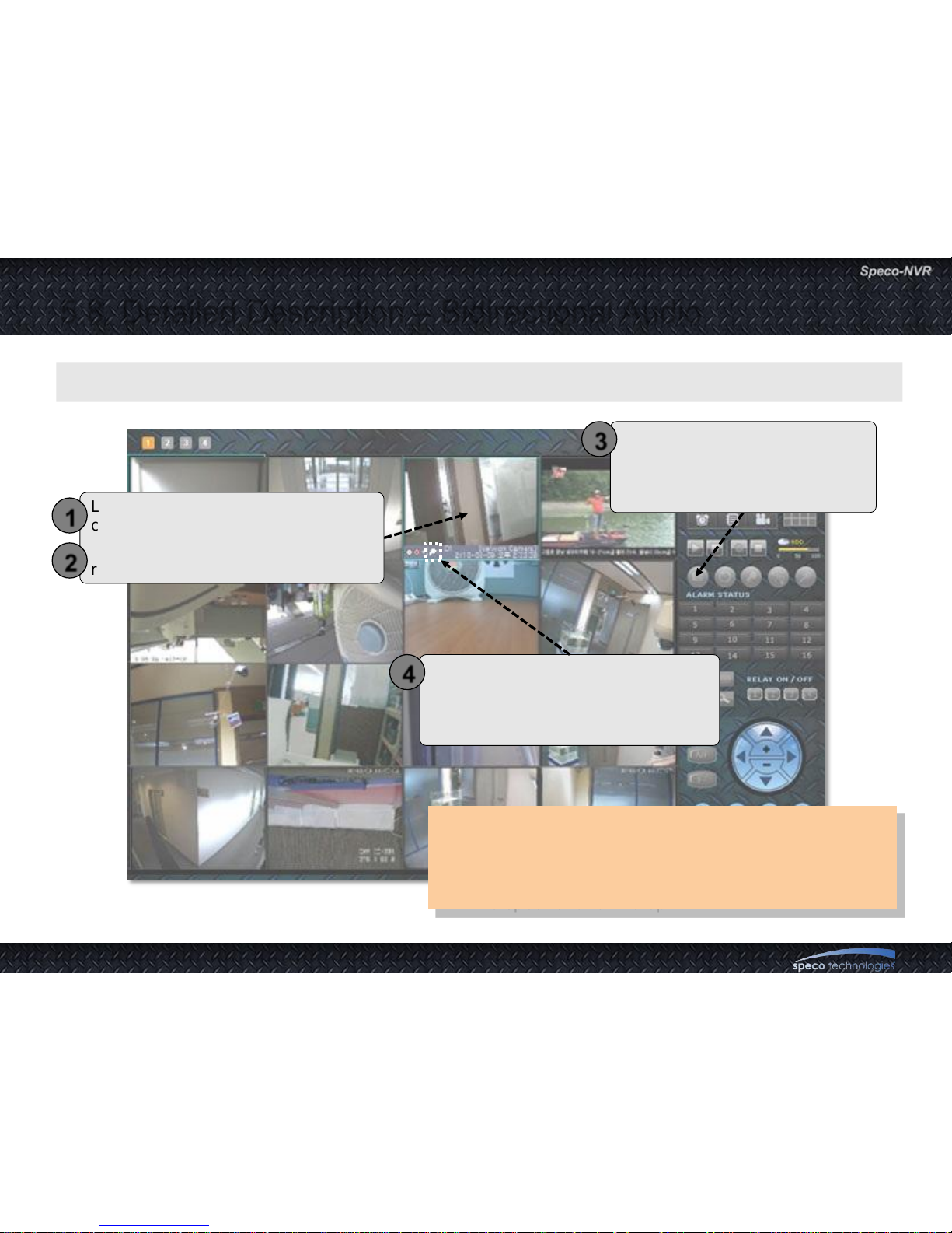
5.8. Detailed Description – Bidirectional Audio
• This feature requires sound card and microphone
on your PC.
• The corresponding device should be equipped with
the speaker and microphone.
A feature enabling bidirectional audio communication with corresponding device.
Locate the cursor on the corresponding
channel and click.
Activated channel is indicated by a blue
rectangle surrounding the DU.
1
2
Click to activate bidirectional audio
communication. This feature
toggles through On/Off every time
the button is clicked.
3
Microphone indicator is shown in bright
color when the bidirectional audio is
enabled. There can be some delay due
to the network delay.
4
Page 36
User Guide Rev 1.0
Page 36
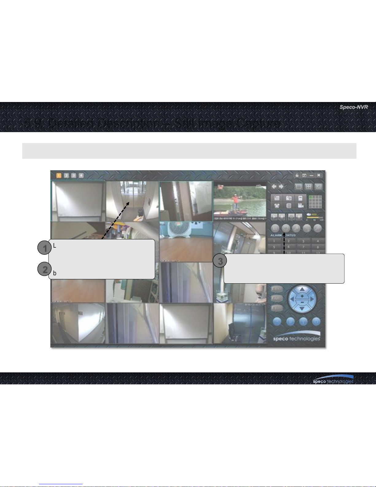
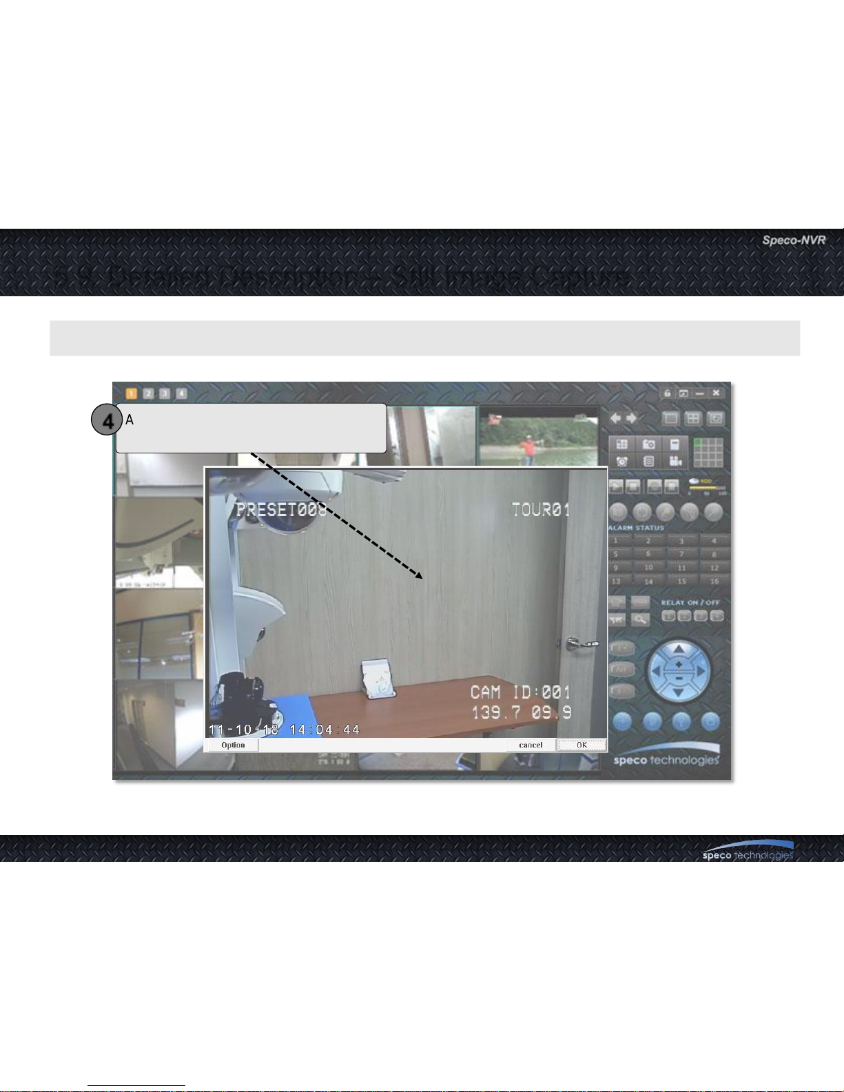
5.9. Detailed Description – Still Image Capture
Locate the cursor on the
corresponding channel and click.
Activated channel is indicated by a
blue rectangle surrounding the DU.
1
2
Click to capture and store the still image
from the corresponding live channel.
Captured video is stored in BMP type.
3
A feature to capture and record still image from a live channel.
Page 37
User Guide Rev 1.0
Page 37
5.9. Detailed Description – Still Image Capture
A feature to capture and record still image from a live channel.
A window pops up and preview captured
image before save it.
4
Page 38
User Guide Rev 1.0
Page 38
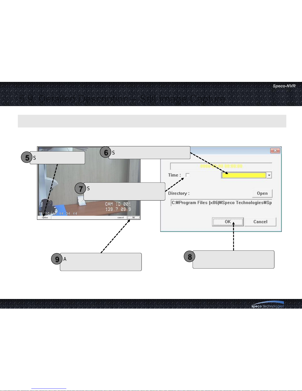
5.9. Detailed Description – Still Image Capture
A feature to capture and record still image from a live channel.
Select check box for Time Stamp.
It will display on Left Top.
7
When all setting is done, click OK
to go next step.
8
Select capture option
5
After check the file name, click
„SAVE‟ to save captured image.
9
Select text color from combo box
6
Page 39
User Guide Rev 1.0
Page 39
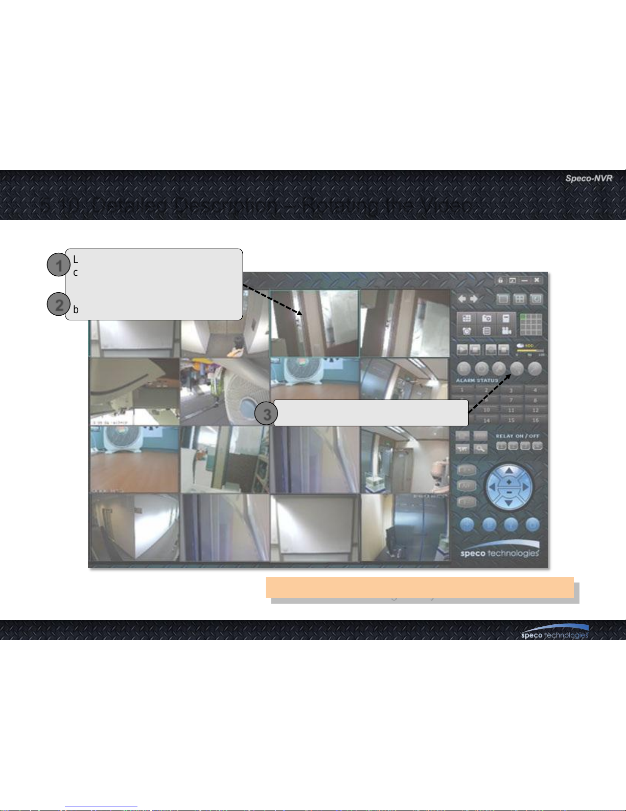
5.10. Detailed Description – Rotating the Video
Locate the cursor on the
corresponding channel and click.
Activated channel is indicated by a
blue rectangle surrounding the DU.
1
2
Click to rotate the video by 180 degree.
3
This feature will not give any effect to recorded video.
Page 40
User Guide Rev 1.0
Page 40
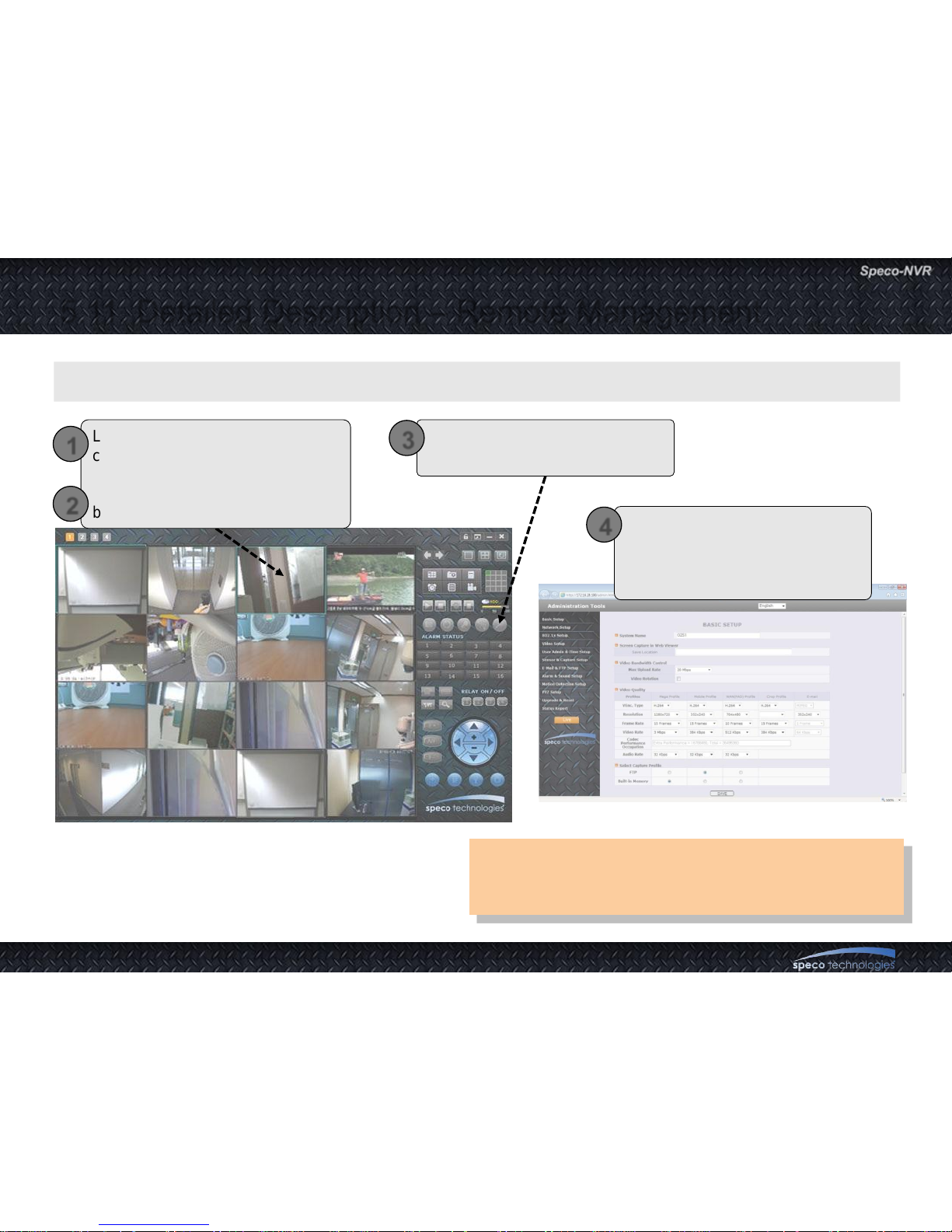
5.11. Detailed Description – Remote Management
Refer to the user manual for the detailed
information about administration page of variable
devices.
A feature to manage the corresponding device over the network
Locate the cursor on the
corresponding channel and click.
Activated channel is indicated by a
blue rectangle surrounding the DU.
1
2
Click to connect to the admin
page of the corresponding device.
3
You are connected to the admin
page through the web browser.
You need the user ID and
password of the administrator.
4
Page 41
User Guide Rev 1.0
Page 41
Refer to the manual of the corresponding device for
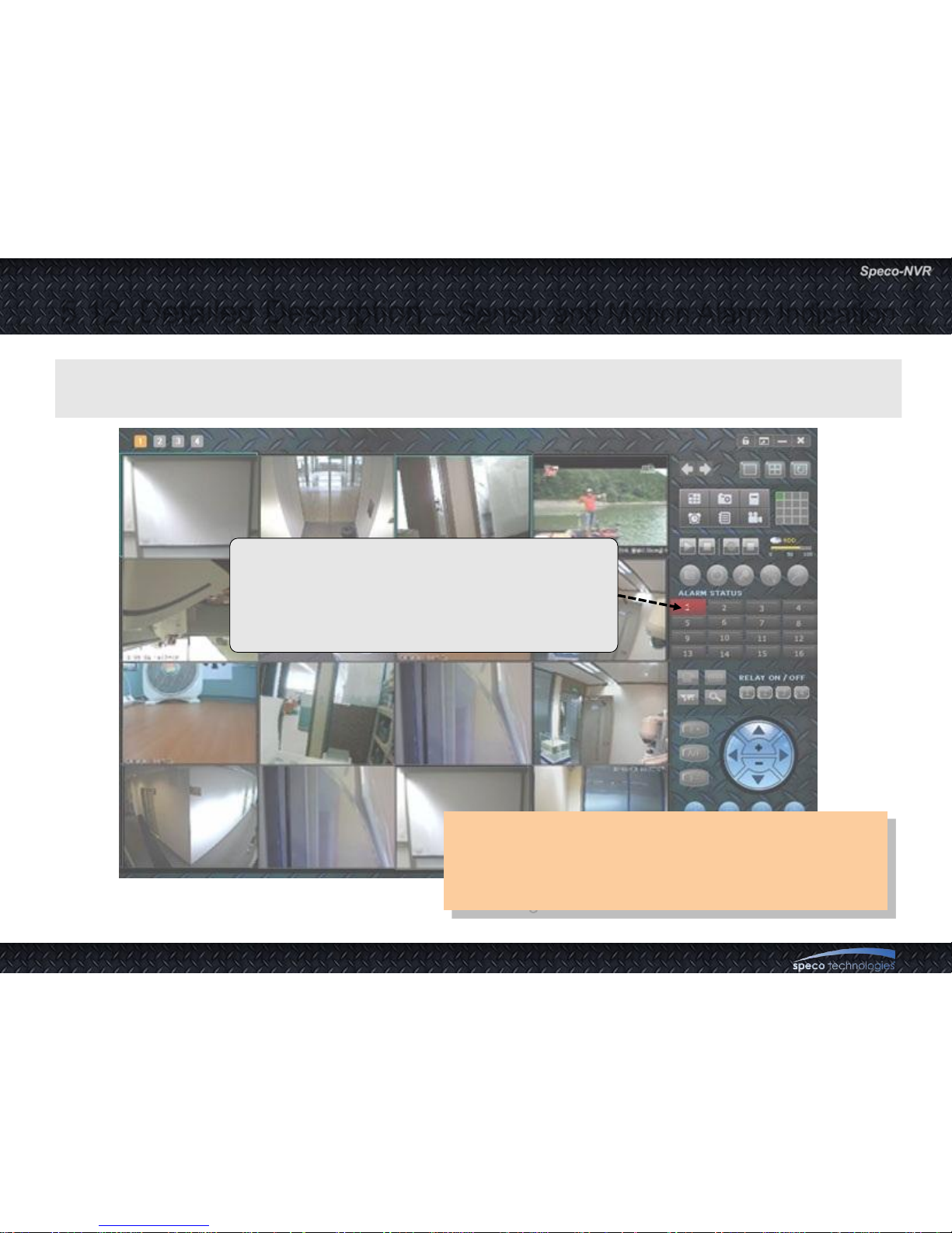
alarm condition set up.
Time duration of blinking is same as the alarm
recording time duration.
5.12. Detailed Description – Sensor and Motion Alarm Indication
If connected device generates alarm by sensor or motion detection, the alarm condition
is transmitted to the Speco-NVR and state is shown on alarm status panel
Click on the highlighted indicator to show Event Log
window. The indicator will be turned off.
When sensor is activated, corresponding lamp will
be lit in RED for the first 2 minutes. The color will be
changed into ORANGE after 2 minutes
Page 42
User Guide Rev 1.0
Page 42
5.13. Detailed Description – Remote Relay On/Off
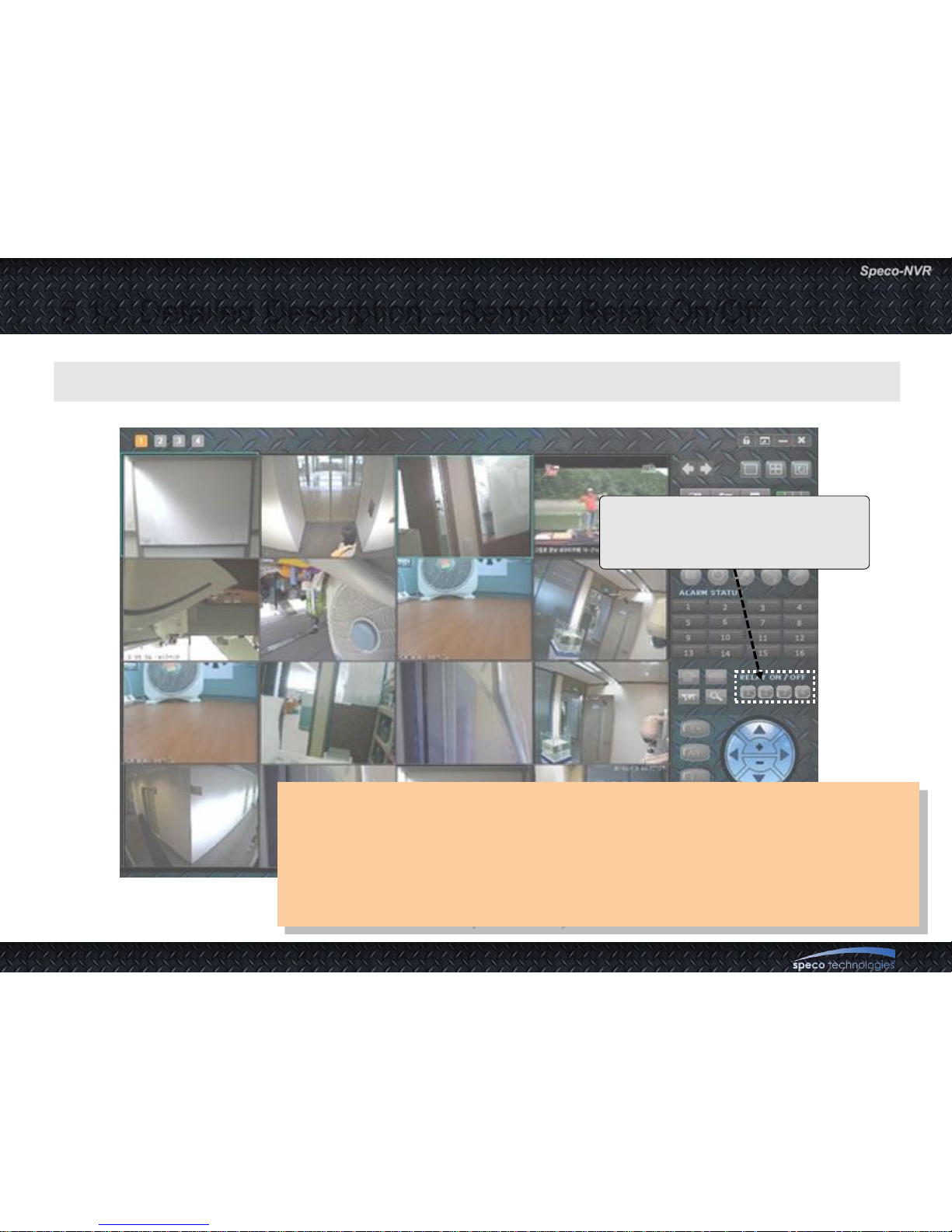
• Refer to the manual of the corresponding device for setting up the relay.
• Regardless of the control, the status of relay can go back to the former
status depending on the set-up of the relay. For example when relay is
programmed for generating alarm signal, the status will change
spontaneously upon alarm condition.
• There can be delay caused by the network.
A feature for On/Off control of the relay remotely.
Up to 2 relays can be controlled
remotely.
Click for On/Off control of the relay.
Page 43
User Guide Rev 1.0
Page 43
5.14. Detailed Description – Video and Audio Adjustment
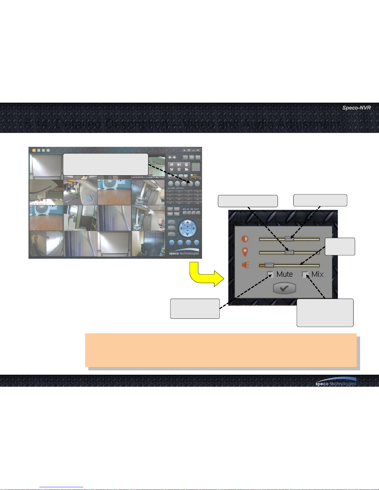
• Audio will be available only when the corresponding device is programmed
to enable the audio.
• Refer to the manual of the corresponding device.
Click to launch Video/Audio
adjustment bar.
Check to mute
the audio.
Check to mix the
sounds from all
live channels.
Contrast control
Brightness control
Volume
control
Page 44
User Guide Rev 1.0
Page 44
5.15.1. Detailed Description – PTZ Control (Centering)
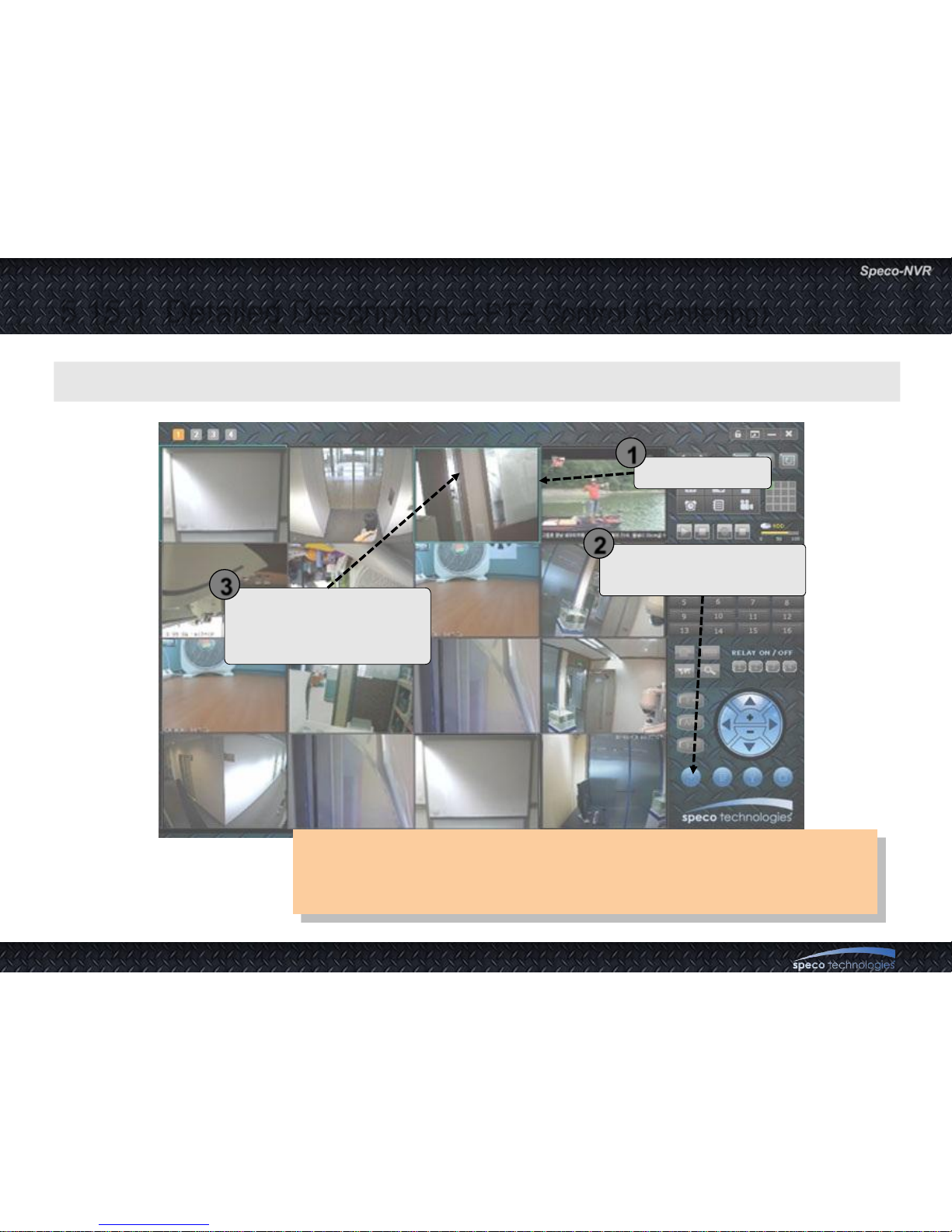
• Pan/Tilt/Zoom and Lens controls are available only when the
corresponding device is equipped with such feature.
• Refer to the manuals of the corresponding device for the details.
Move the cursor and click
on the point to move the
camera center to.
Click to activate centering.
Click again to deactivate.
Select channel
A feature to move the center of the camera to the point of cursor.
1
2
3
Page 45
User Guide Rev 1.0
Page 45
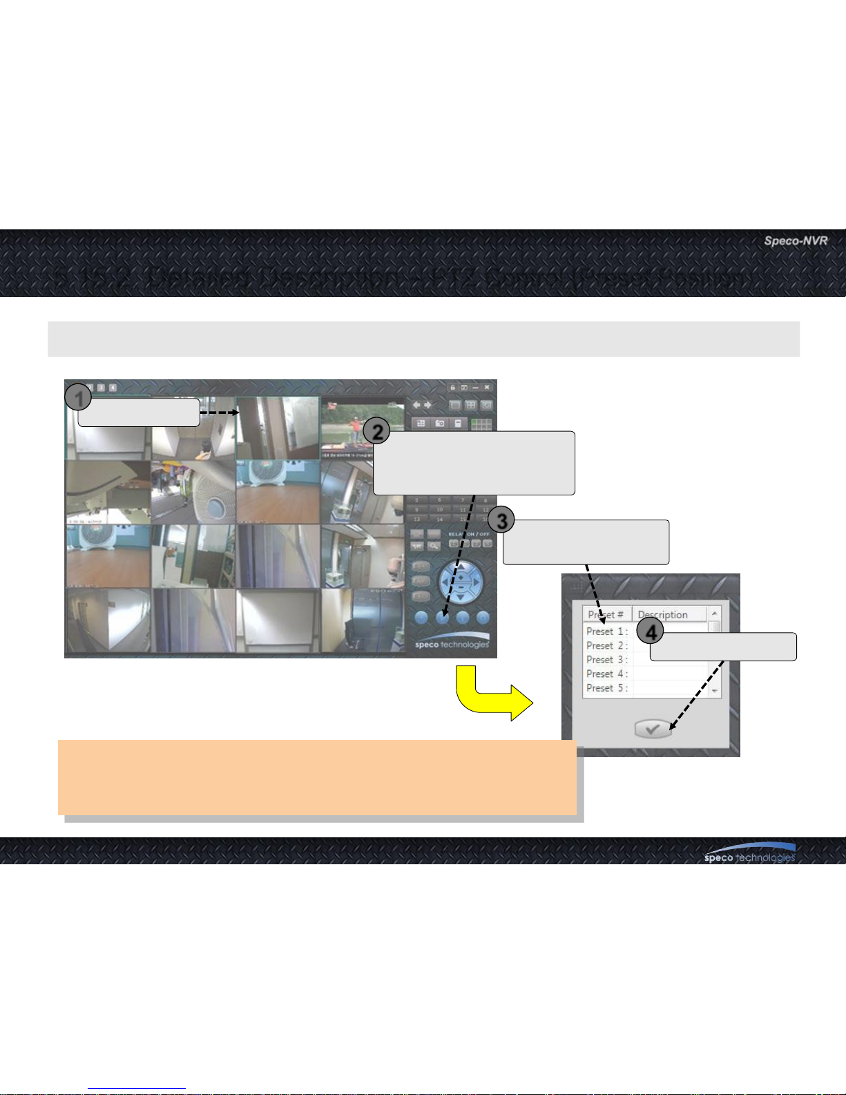
5.15.2. Detailed Description – PTZ Control (Preset Position)
A feature to move the view point of the camera to pre-defined position.
• Pan/Tilt/Zoom and Lens controls are available only when the
corresponding device is equipped with such feature.
• Refer to the manuals of the corresponding device for the details.
Click to activate movement
to preset position feature.
Preset list will be popped up
Double click on desired
preset position.
Finish the operation.
Select channel
1
2
3
4
Page 46
User Guide Rev 1.0
Page 46
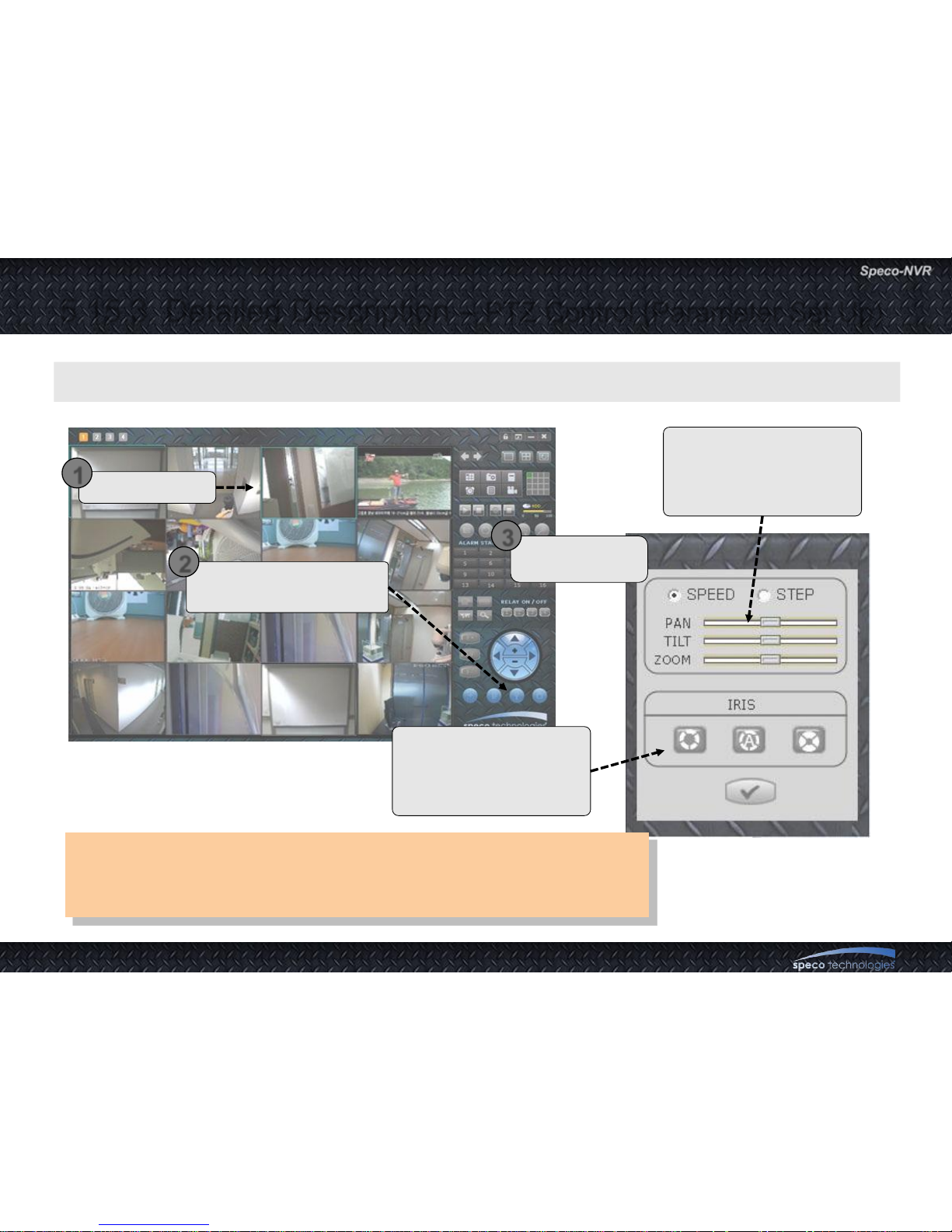
5.15.3. Detailed Description – PTZ Control (Parameter Set Up)
A feature to set up parameters for PTZ and Lens control.
Select channel
1
Click to launch parameter
set up window.
2
Adjust speed or
step of PTZ.
3
IRIS control. Press each
button for the control.
Wider, auto, narrower
from the left.
Enable the Pan/tilt
device to continuously
scan through the set up
region.
• Pan/Tilt/Zoom and Lens controls are available only when the
corresponding device is equipped with such feature.
• Refer to the manuals of the corresponding device for the details.
Page 47
User Guide Rev 1.0
Page 47
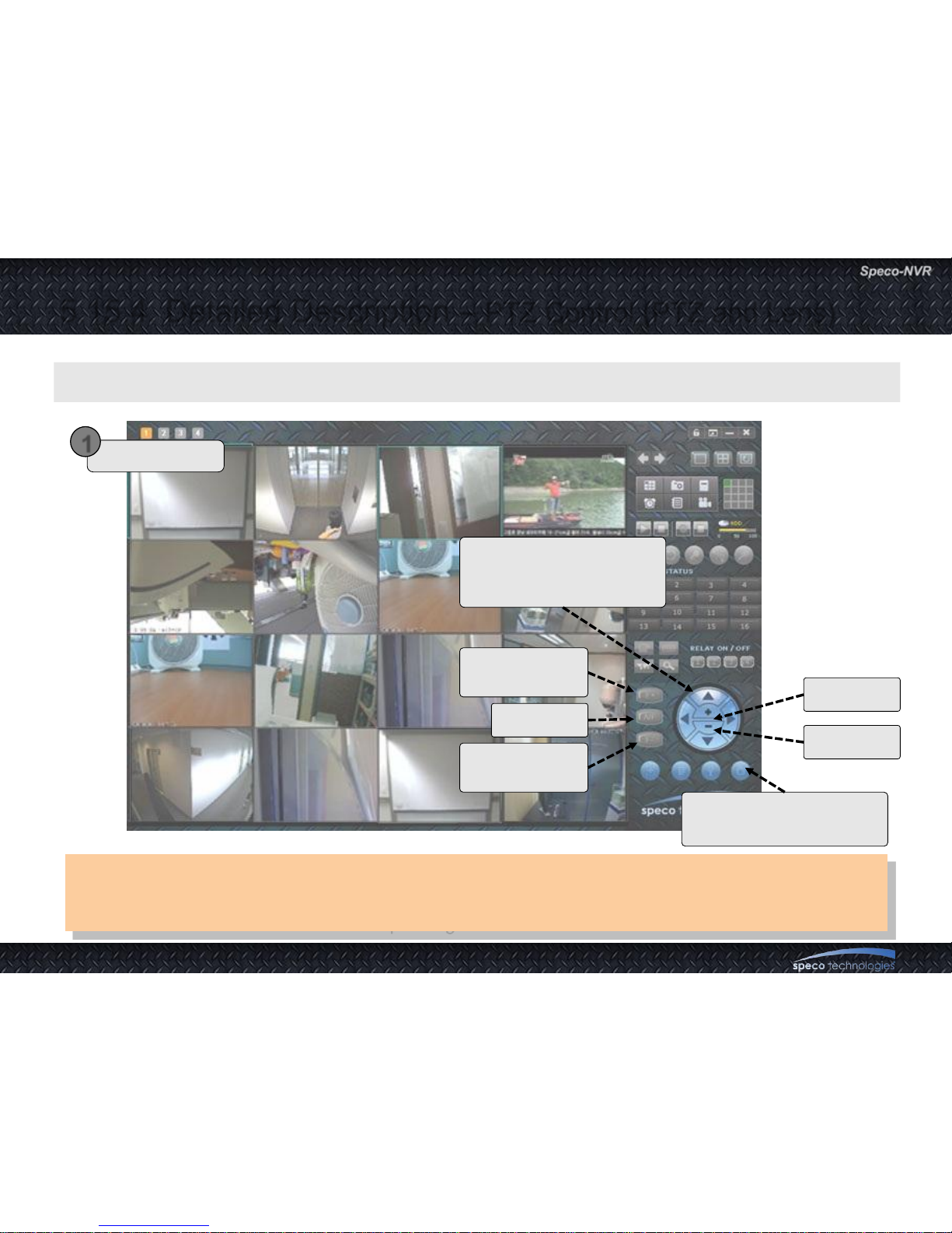
5.15.4. Detailed Description – PTZ Control (PTZ and Lens)
A feature to control the PTZ and Lenz manually for the selected channel.
Select channel
1
Activate PTZ device to go
back to home position.
Focus to
farther position
Auto focus.
Focus to
closer position.
Zoom In
Zoom Out
Move the camera to the
direction indicated by the
arrow head.
• Pan/Tilt/Zoom and Lens controls are available only when the corresponding device is equipped
with such feature.
• Refer to the manuals of the corresponding device for the details.
Page 48
User Guide Rev 1.0
Page 48
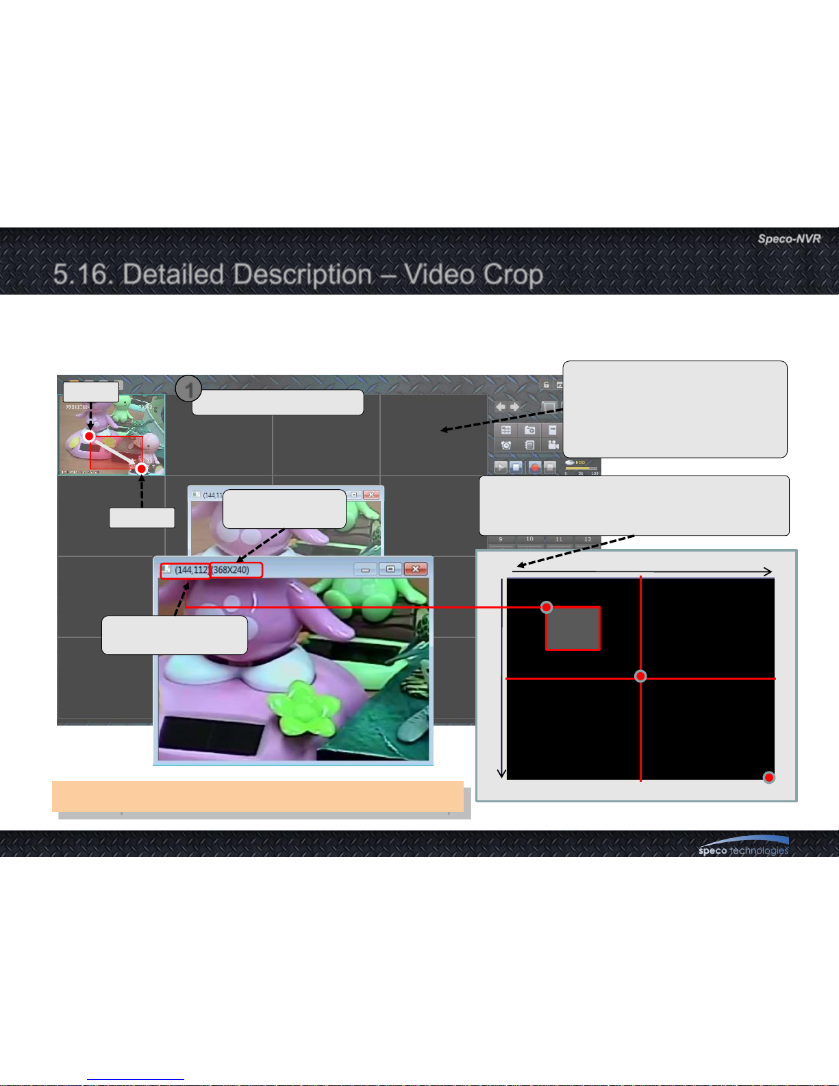
190, 179
0
Max Res. 1600
Max Res. 1200
800
600
800, 600
1599, 1199
5.16. Detailed Description – Video Crop
Select the region to crop
1
Click
Dragging
Size of the
cropped region
Cropped video is available from
channel 3 of the corresponding
product. (Refer to “Basic Setup”
from the corresponding product‟s
manual.)
Coordinate values in case of UXGA size video:
Upper left corner : (0,0)
Lower right corner : (1599,1199)
It is up to 352 x 240 to resolution of video crop.
Upper left corner of
the crop region
Page 49
User Guide Rev 1.0
Page 49
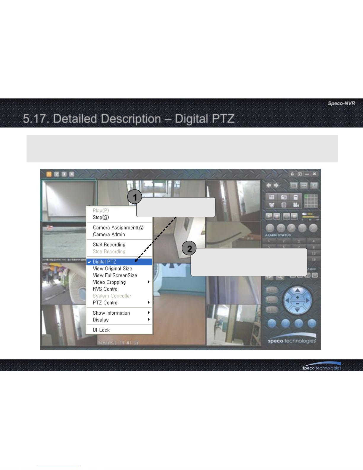
5.17. Detailed Description – Digital PTZ
Select the Digital PTZ of
pop-up menu.
1
Scroll the mouse wheel for video to
zoom in/out and drag mouse for video
to move to left, right, up and down.
2
Digital PTZ is feature that moves for video to left, right, up and down or zoom in/out
by mouse control.
Page 50
User Guide Rev 1.0
Page 50
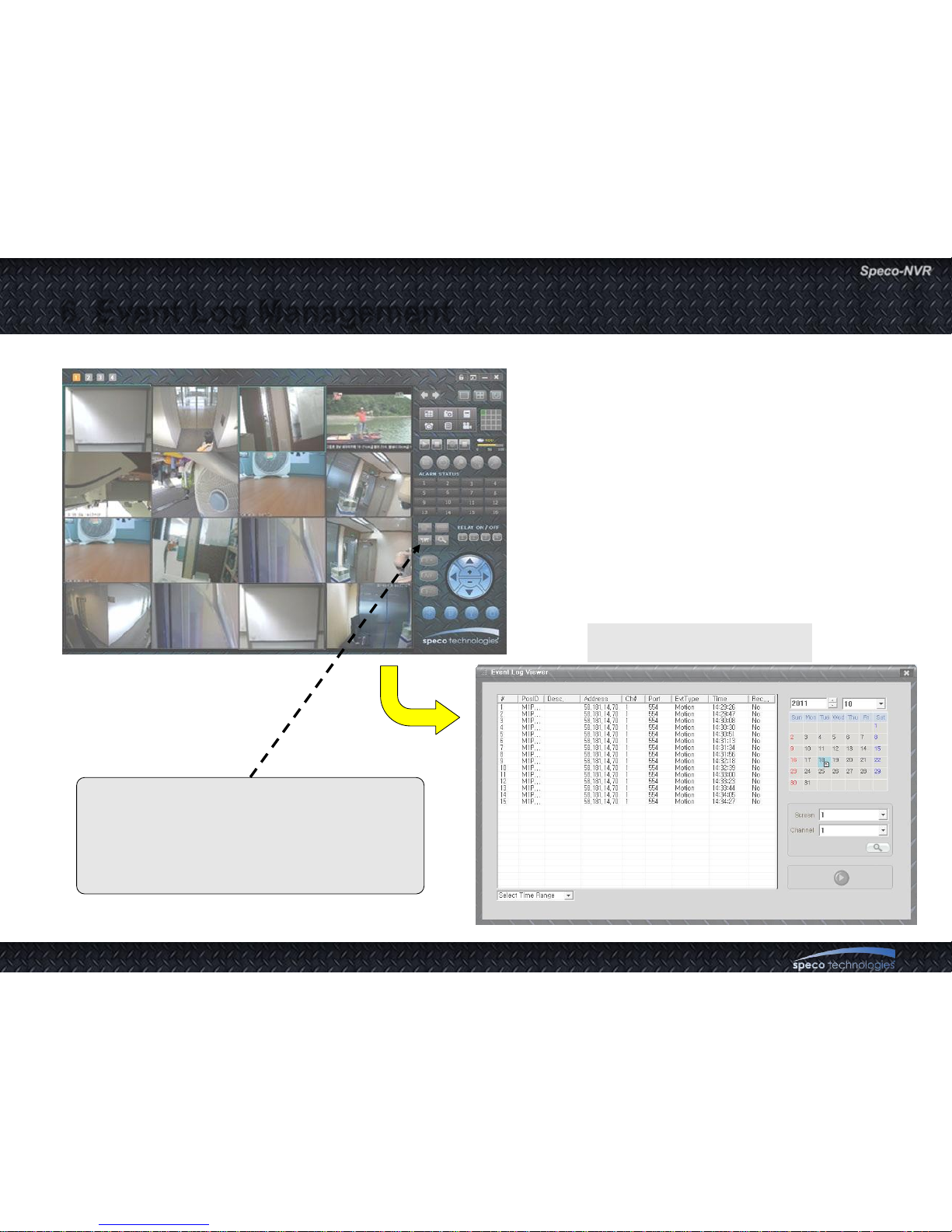
6. Event Log Management
Event Log Window
Event indicator is highlighted upon event
(Sensor, Motion, No Video, and Video
Recovered)
Click on the highlighted indicator to show
Event Log Window.
Page 51
User Guide Rev 1.0
Page 51
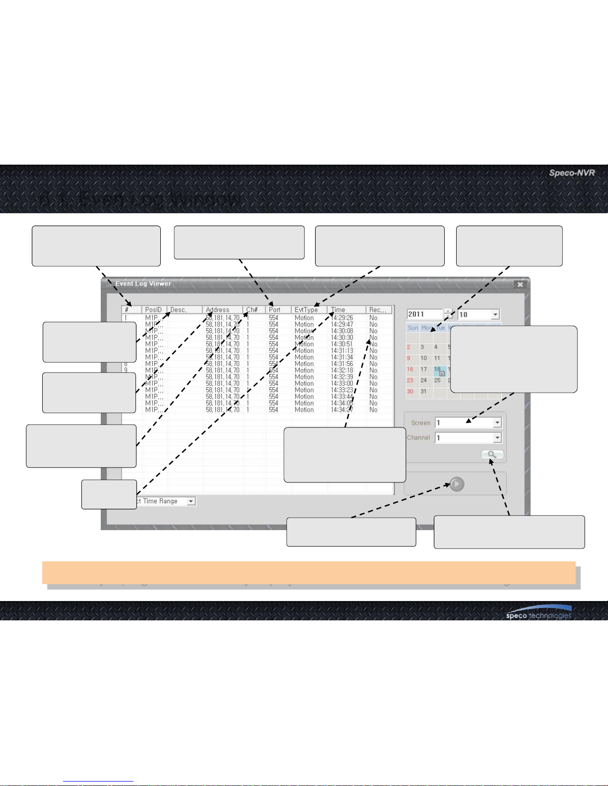
6.1. Even Log Window
icfPlayer program is necessary to play the recorded video file at Event Log Window
RTSP port which was set
during IP assignment.
Event type : Motion,
Sensor-1,2,3,4, No Video,
Video Recovery
Highlighted when
there is event log on
the date.
Position of video channel
at Speco-NVR
screen
Description which
was set during IP
assignment.
IP Address which
was set during IP
assignment
Channel number
which was set
during IP assignment
Time of
the event
“Yes” means that there
is recorded video file for
the event. Double click
to view recorded video
Play the recorded file with
the icf player program.
Start searching of event log
for the specified video channel
Designate the video
channel for retrieving the
event log. Enter screen
and channel numbers.in
the corresponding fields.
Page 52
User Guide Rev 1.0
Page 52
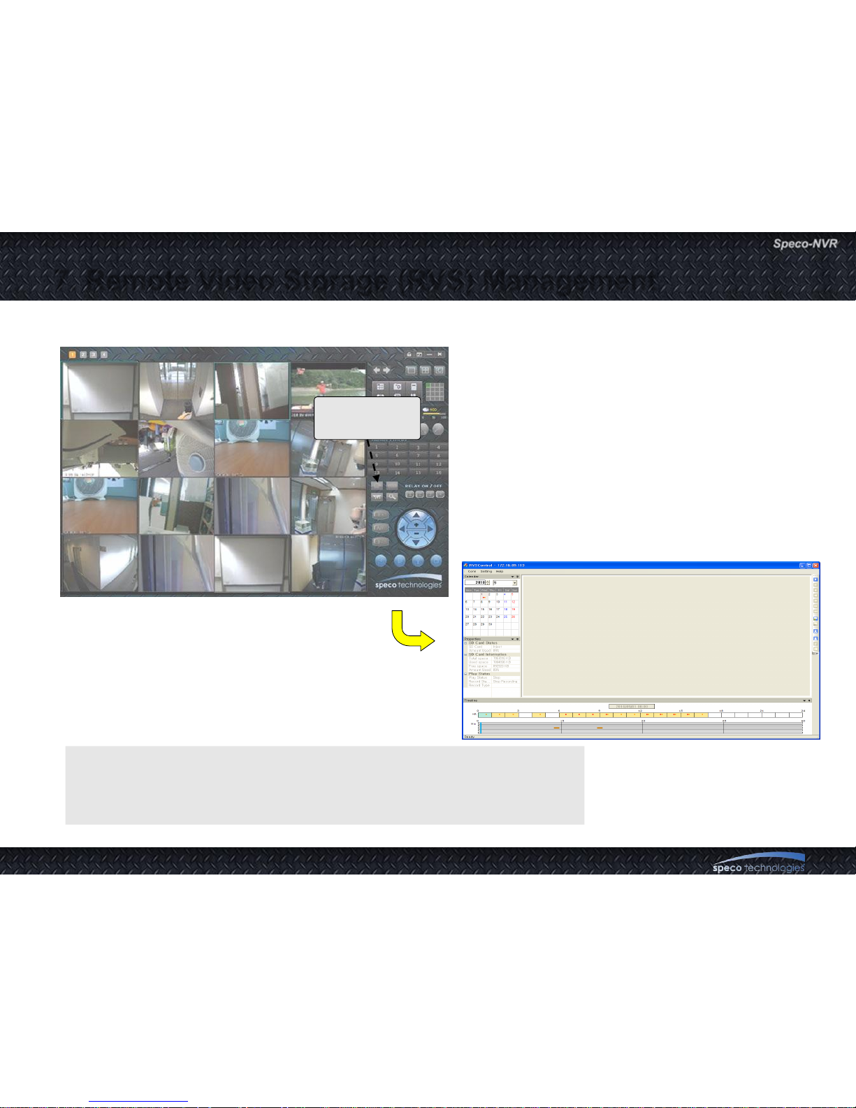
7. Remote Video Storage (RVS) Management
Target Application
- Management of video storage in IP Camera and Video Server.
RVS Control
Button
Page 53
User Guide Rev 1.0
Page 53
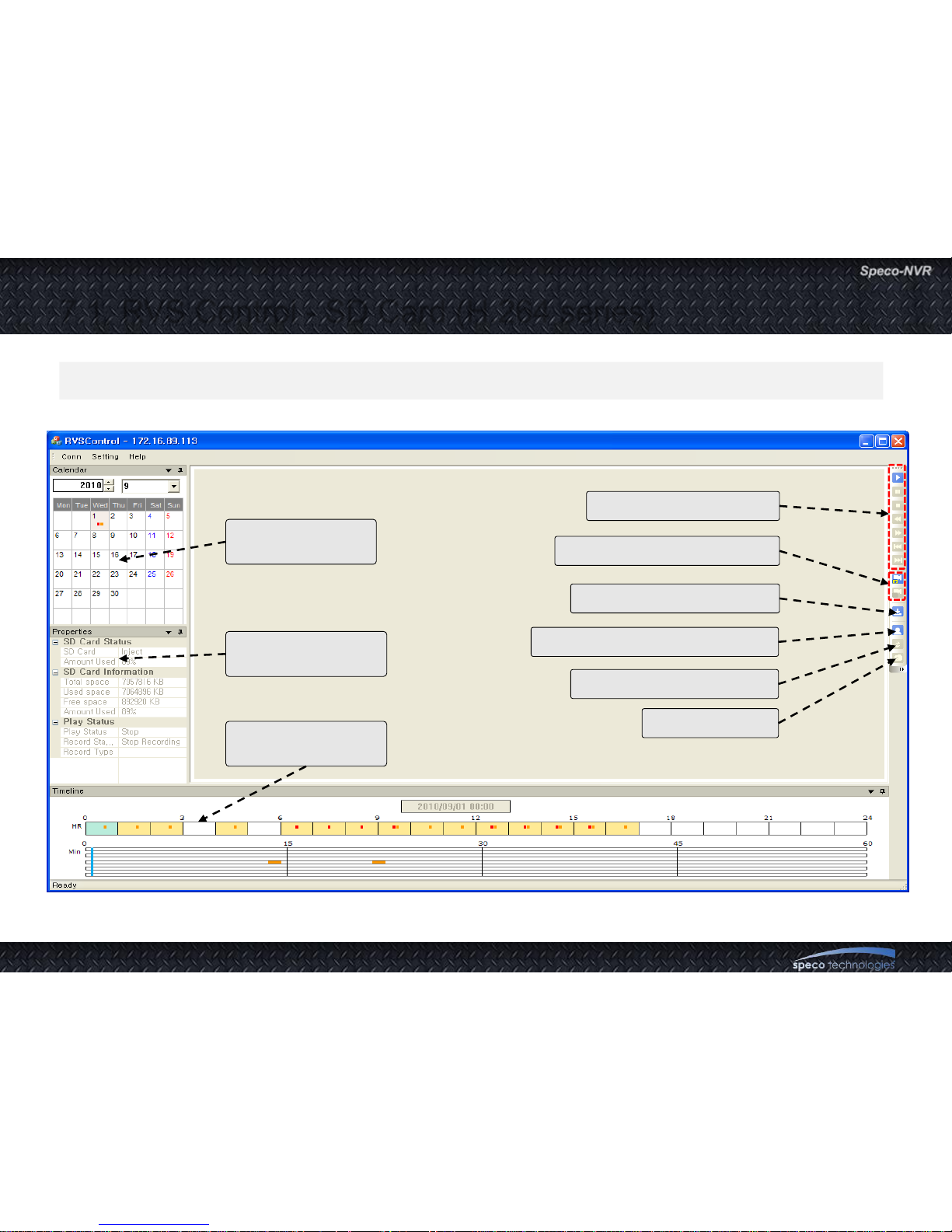
7.1. RVS Control - SD Card (H.264 series)
RVS Control screen
This feature is targeted to control H.264 cameras & servers having its own SD card.
Monthly recording
information
Connected device‟s
storage information
Timeline for
recorded data
Playback control buttons
Recording Start / Stop button
Download recorded video
Connect to Administration Tools
Rotate video upside down
Take a snapshot
Page 54
User Guide Rev 1.0
Page 54
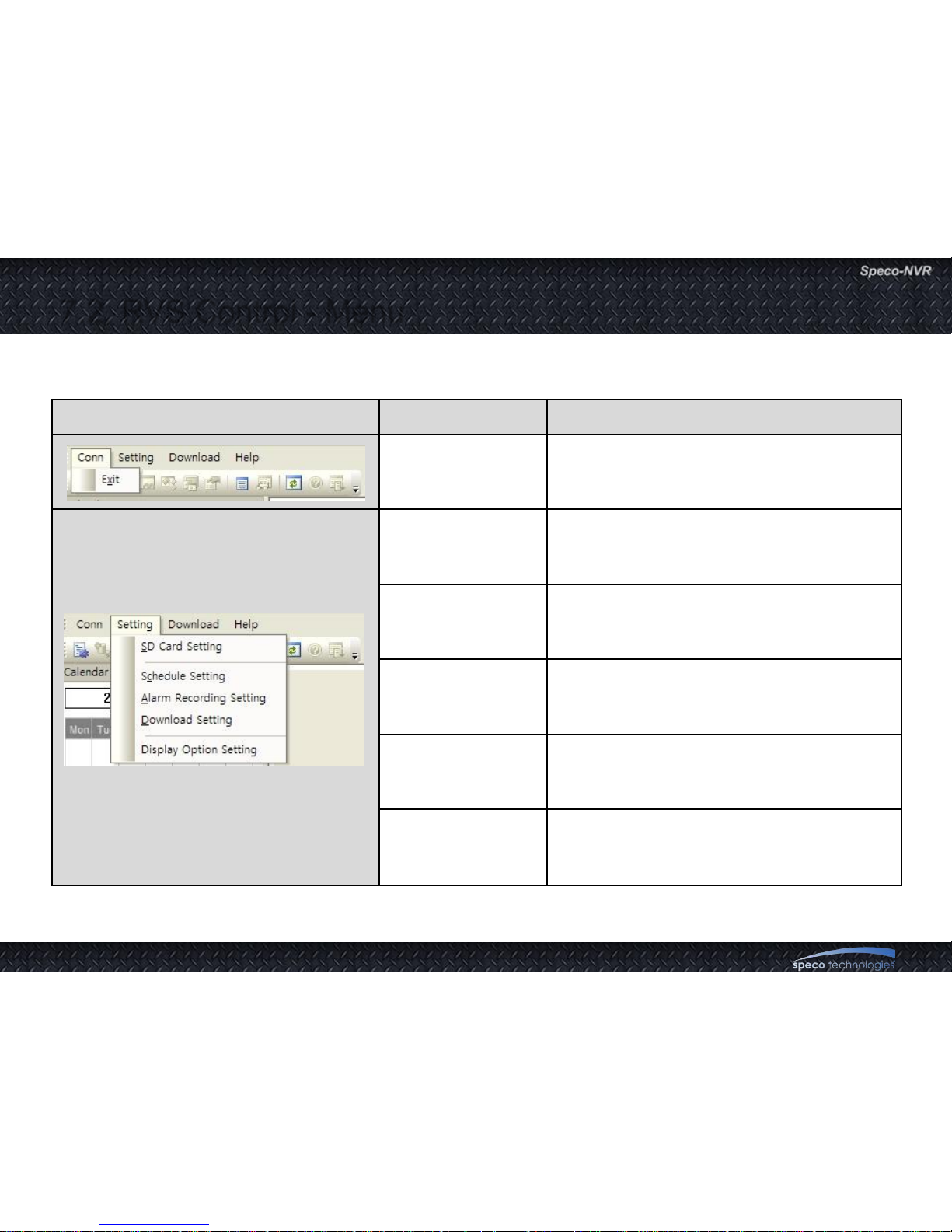
Menu Sub menu Description
Exit Close RVS control.
SD Card
Setting
Set recording options.
Schedule
Setting
Set recording schedule.
Alarm Recording
Setting
Set alarm recording duration.
Download
Setting
Set the download folder and file format.
Display Option
Setting
Control contrast & brightness and audio
volume for playback.
7.2. RVS Control - Menu
Page 55
User Guide Rev 1.0
Page 55
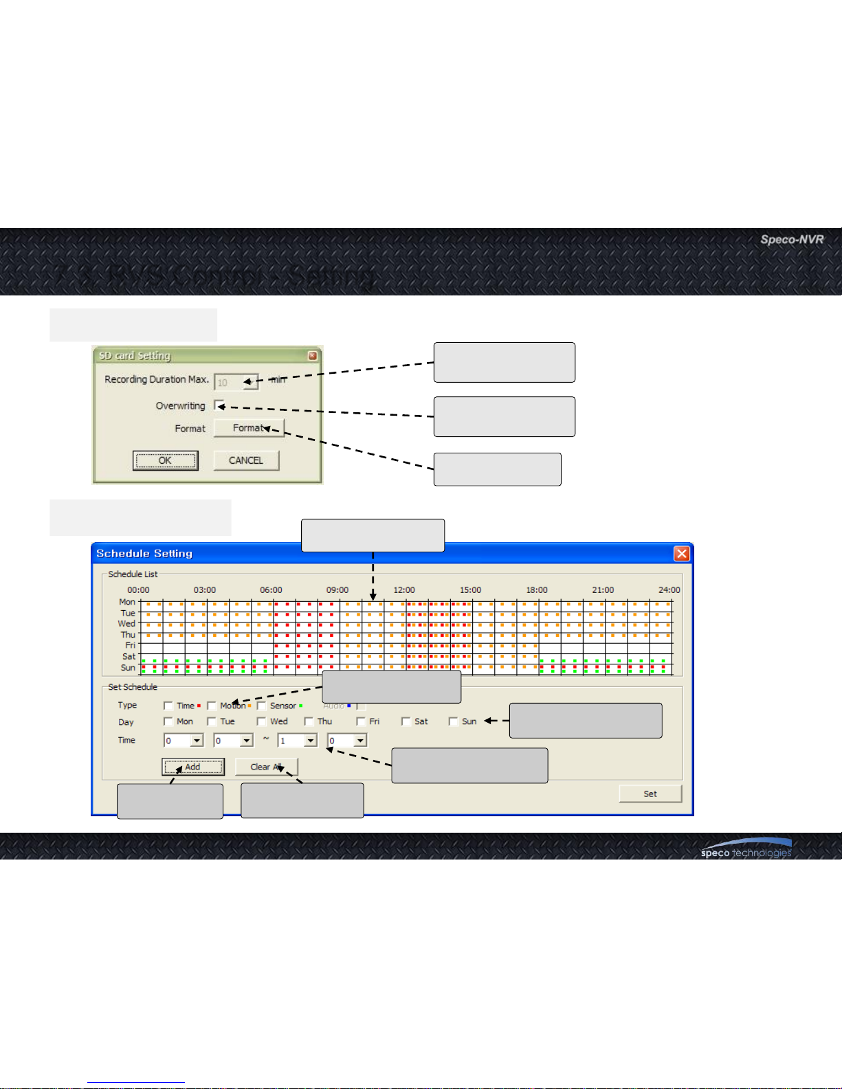
SD card Setting
Schedule Setting
7.3. RVS Control - Setting
Maximum duration
for recording
Enable/Disable
overwrite recording
Format SD card
Recording schedule
display screen
Select trigger type
for recording
Select day which you
want apply recording
Set the start time and
end time for recording
Add recording
schedule
Delete recording
schedule
Page 56
User Guide Rev 1.0
Page 56
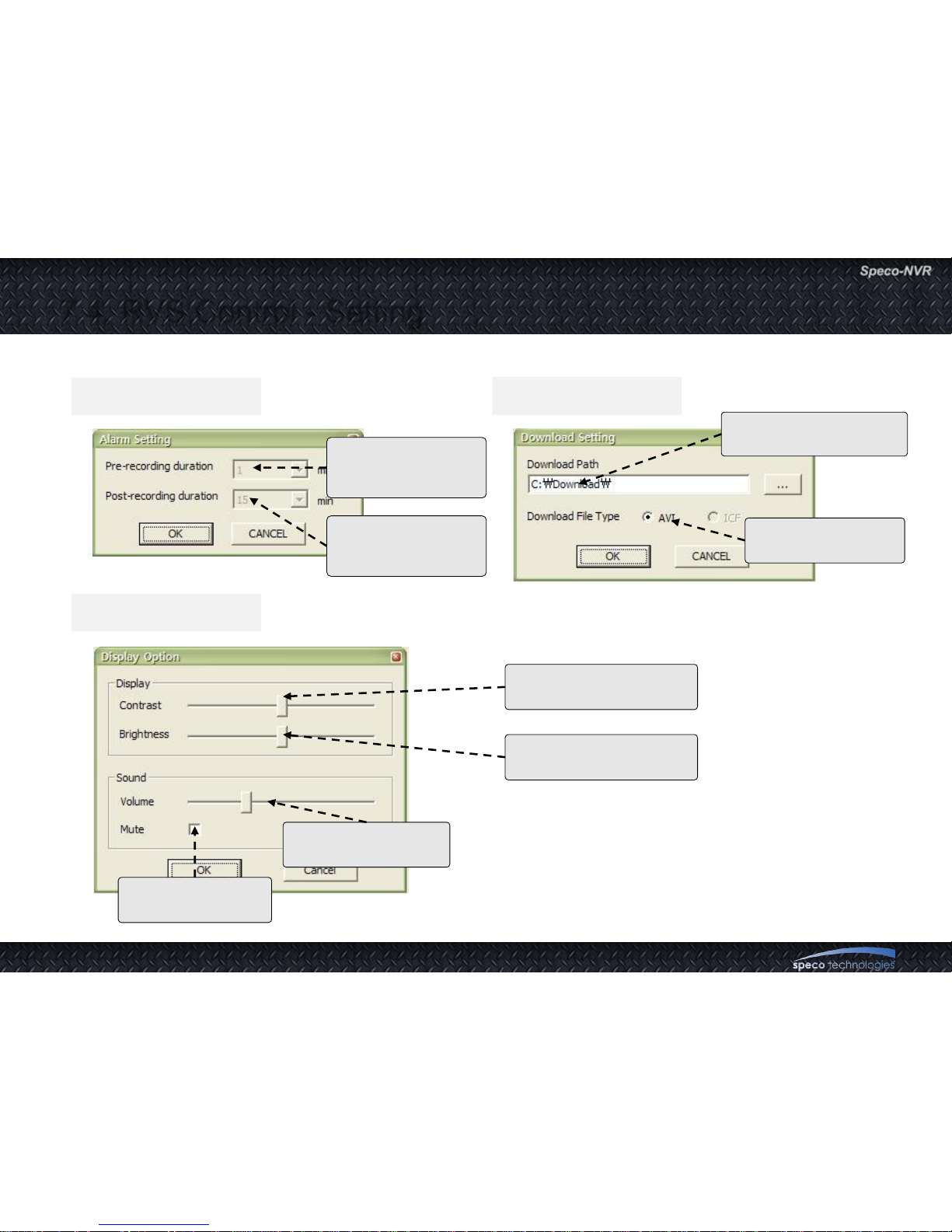
Alarm Setting
Display Setting
Download Setting
7.4. RVS Control - Setting
Control audio
volume of playback
Mute audio sound
of playback
Select file format
for downloaded file
Assign a folder for
download recorded file
Control video contrast of
playback screen
Control video brightness
of playback screen
Alarm recording
duration before the
event happen
Alarm recording
duration after the
event happen
Page 57
User Guide Rev 1.0
Page 57
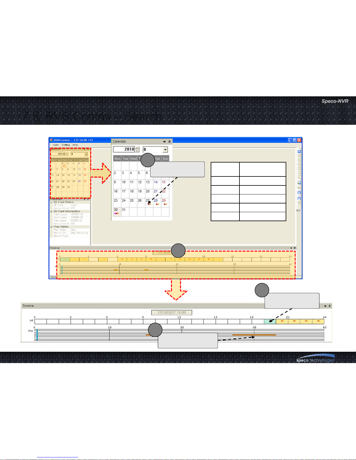
7.5. RVS Control – Search
3
Select recorded
time from timeline
2
Marked
Color
Recording Type
Purple Panic Recording
Red Time Recording
Orange Motion Recording
Green Sensor Recording
Blue Audio Recording
Select a day from
calendar
1
Select specific time
from timeline bar
3
Page 58
User Guide Rev 1.0
Page 58
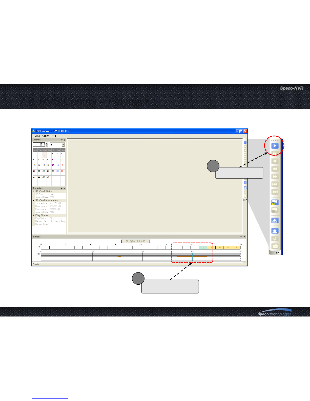
7.6. RVS Control – Playback
Click Play button
2
Select target time that
want to playback
1
Page 59
User Guide Rev 1.0
Page 59
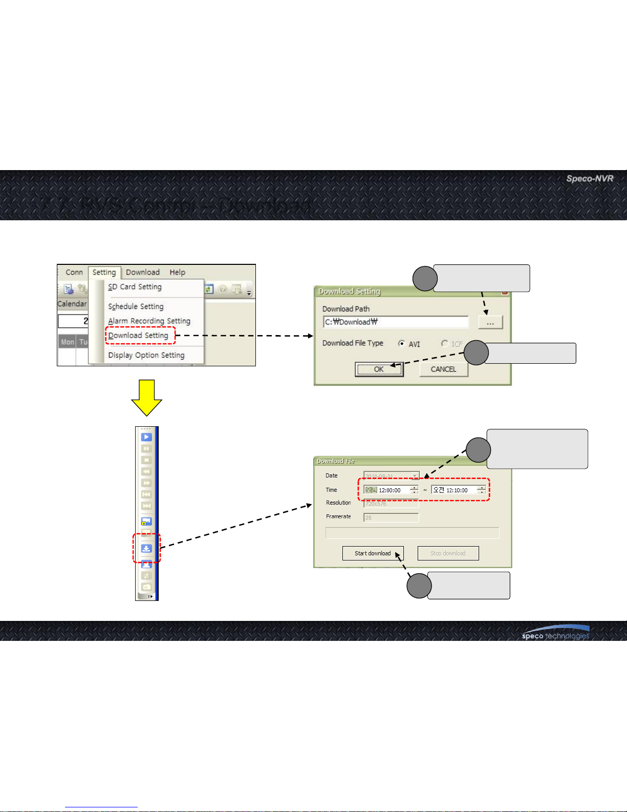
7.7. RVS Control – Download
Select a folder for
downloaded file
1
Select file format
2
Set start time and
end time to extract
recorded video
3
Click button to
start download
4
Page 60
User Guide Rev 1.0
Page 60
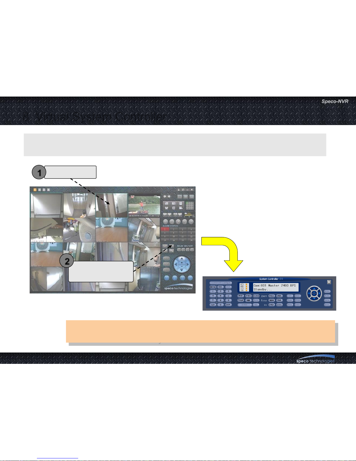
8. Virtual System Controller
There are many powerful features supported by Virtual System Controller.
Please refer to “Virtual System Controller User‟s Manual” for the details.
Virtual System Controller is a program module that emulate keyboard controller for PTZ
cameras. This feature is supported OPTZ36XI. OPTZ36XO.
Select a channel
Click to launch Virtual
System Controller.
1
2
Page 61
User Guide Rev 1.0
Page 61
9. Screen Lock & Unlock
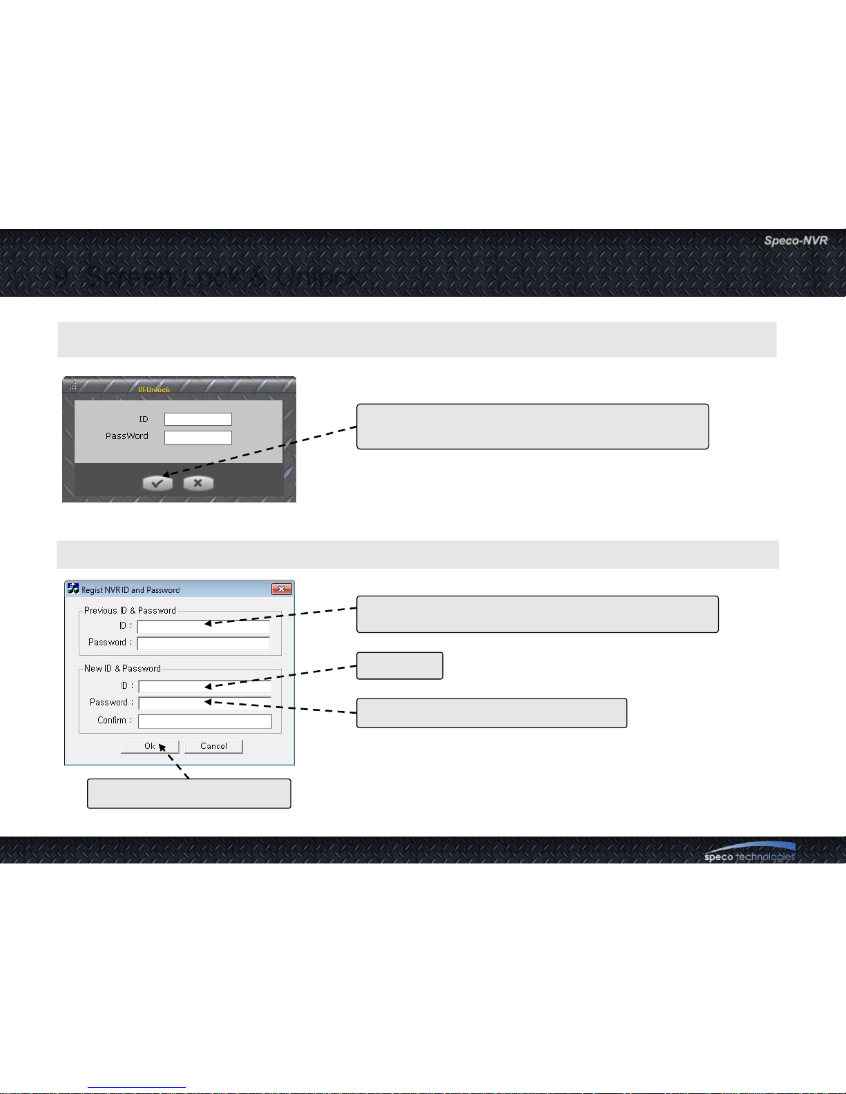
The program can be terminated only after the valid ID and password are entered.
To assign new ID and password run „program files>NVR->RegistNVRIDPwd”.
Default value is empty.
Just click on the this button to initiate the termination.
Existing ID and password. Skip this upon initial setting.
New ID.
Enter password for new ID and confirm
Click OK to finish the setting.
Page 62
User Guide Rev 1.0
Page 62
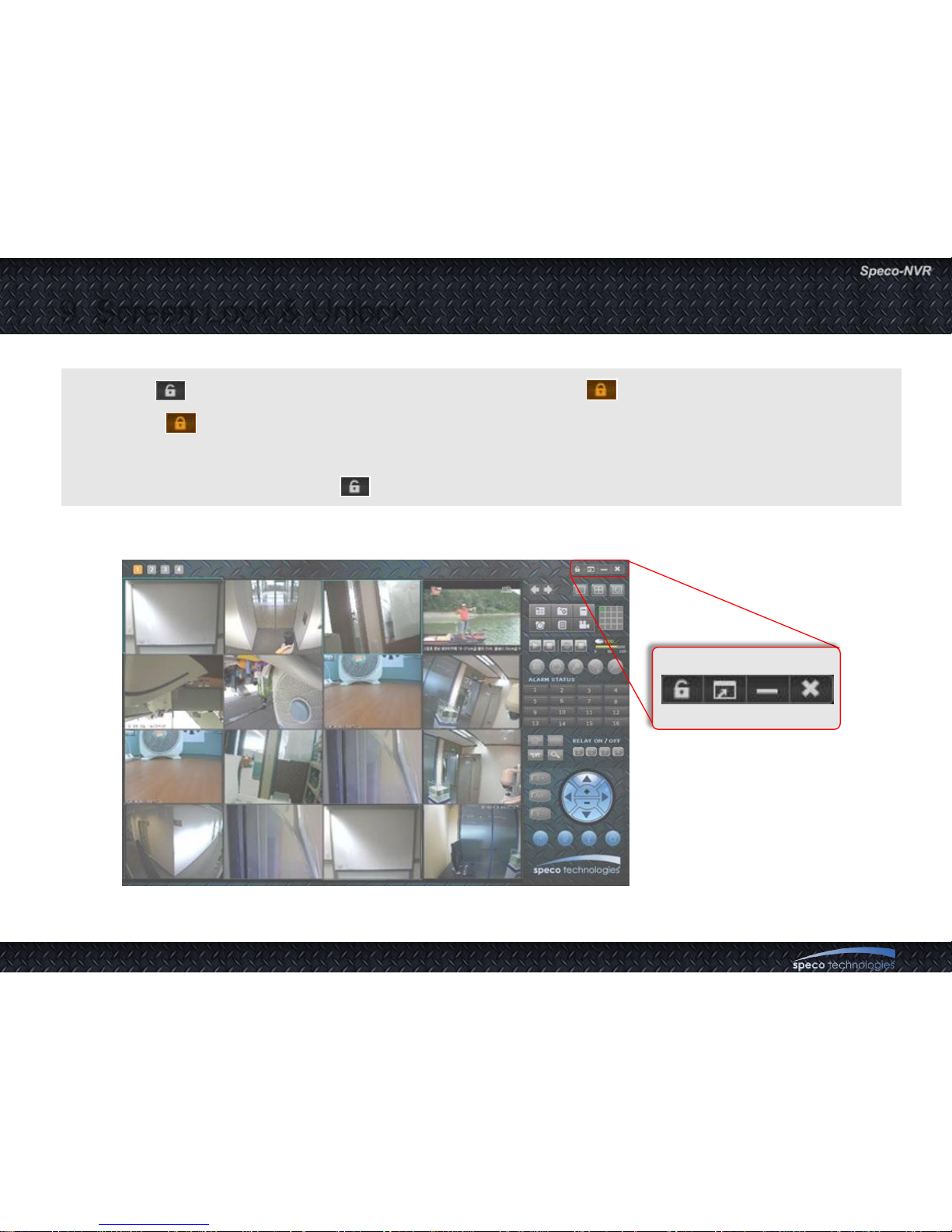
1. Click to lock the program. The icon will be changed to .
2. When is clicked after the program is locked, Speco-NVR will ask for ID and password to
unlock the program.
3. The icon will be changed to after unlock.
9. Screen Lock & Unlock
Page 63
User Guide Rev 1.0
Page 63
10. E-MAP
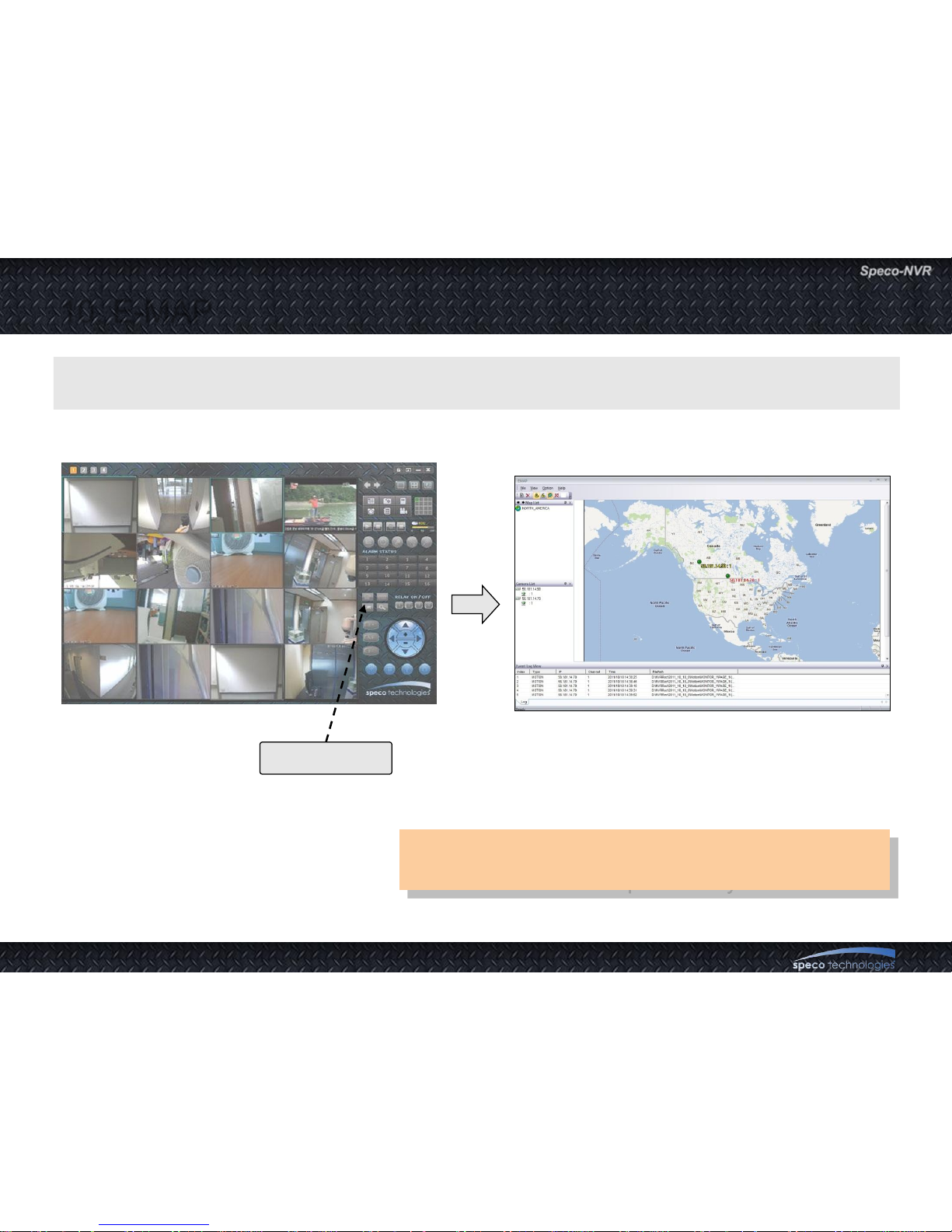
Map Data is not provided.
Mad data should be provided by the installer.
E-Map is a feature to position the cameras and video from them on map images.
E-Map Controller
Initiate E-Map
Page 64
User Guide Rev 1.0
Page 64
10.1. E-Map – GUI
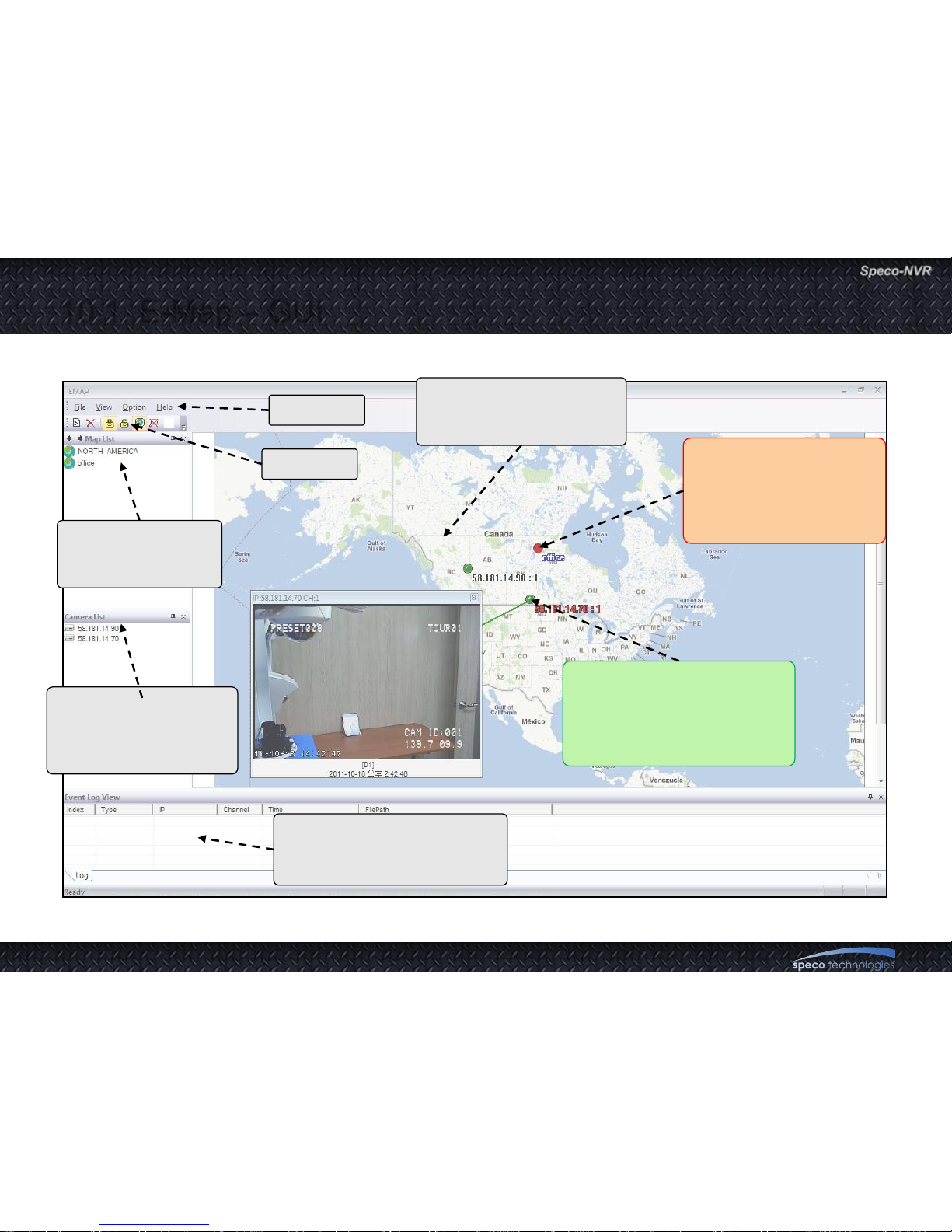
Map Icon : Indicates
another registered map.
It supports image
preview and moving to
another map.
Camera Icon :
• Dark green circle indicates a
camera not connected.
• Bright green circle indicates
camera connected.
Map Window : Location of
the cameras are shown on
the map image.
Camera List :
The cameras registered
in the Speco-NVR are
displayed.
Event Log Window : Events
such as Play, Stop and
Alarms are shown
Map information
window : Registered
maps are displayed
Tool Bar
Menu Bar
Page 65
User Guide Rev 1.0
Page 65
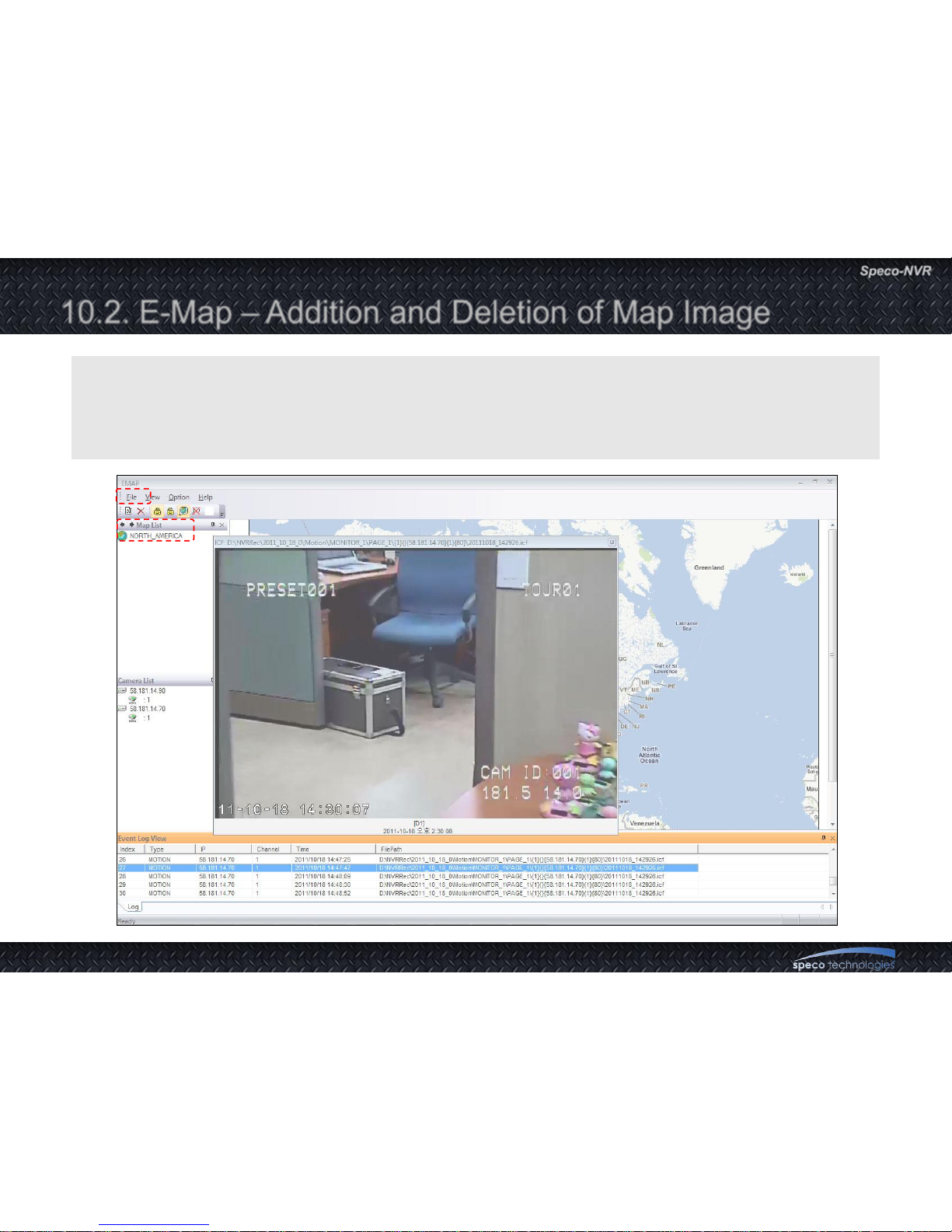
10.2. E-Map – Addition and Deletion of Map Image
1. Move to other map : Double click on the map data.
2. Addition and deletion of map
: Select a map to add or delete and choose Menu -> File -> New Map or Delete Map.
3. Map file support BMP format.
Page 66
User Guide Rev 1.0
Page 66
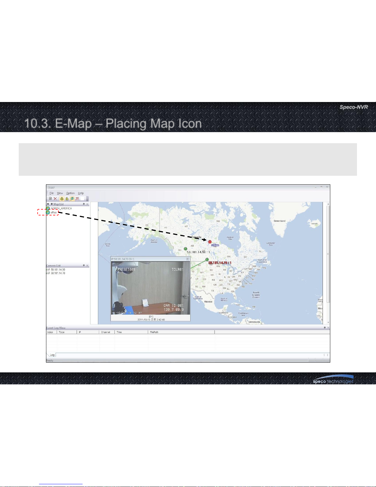
10.3. E-Map – Placing Map Icon
Multi-Map : Select a map data from the map information window and then perform Drag & Drop to
place a Map Icon on the Map window.
The Map Icon can be double clicked to move to the map.
Page 67
User Guide Rev 1.0
Page 67
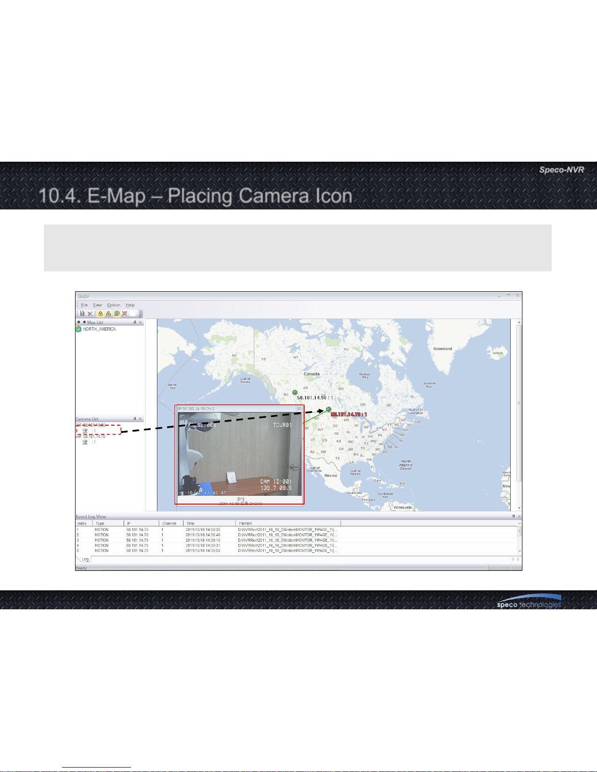
10.4. E-Map – Placing Camera Icon
Select a camera data from the camera list and then perform Drag & Drop to place a camera
Icon on the Map window.
Page 68
User Guide Rev 1.0
Page 68
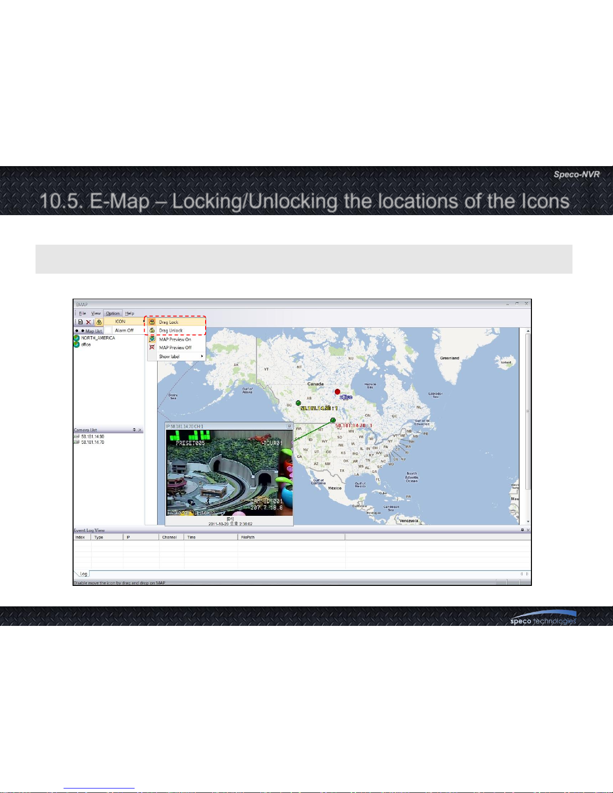
10.5. E-Map – Locking/Unlocking the locations of the Icons
Select Drag Lock or Drag Unlock from Menu -> Icon to lock or unlock the location of the icons.
Page 69
User Guide Rev 1.0
Page 69
10.6. E-Map –Msp and Camera Status Indication
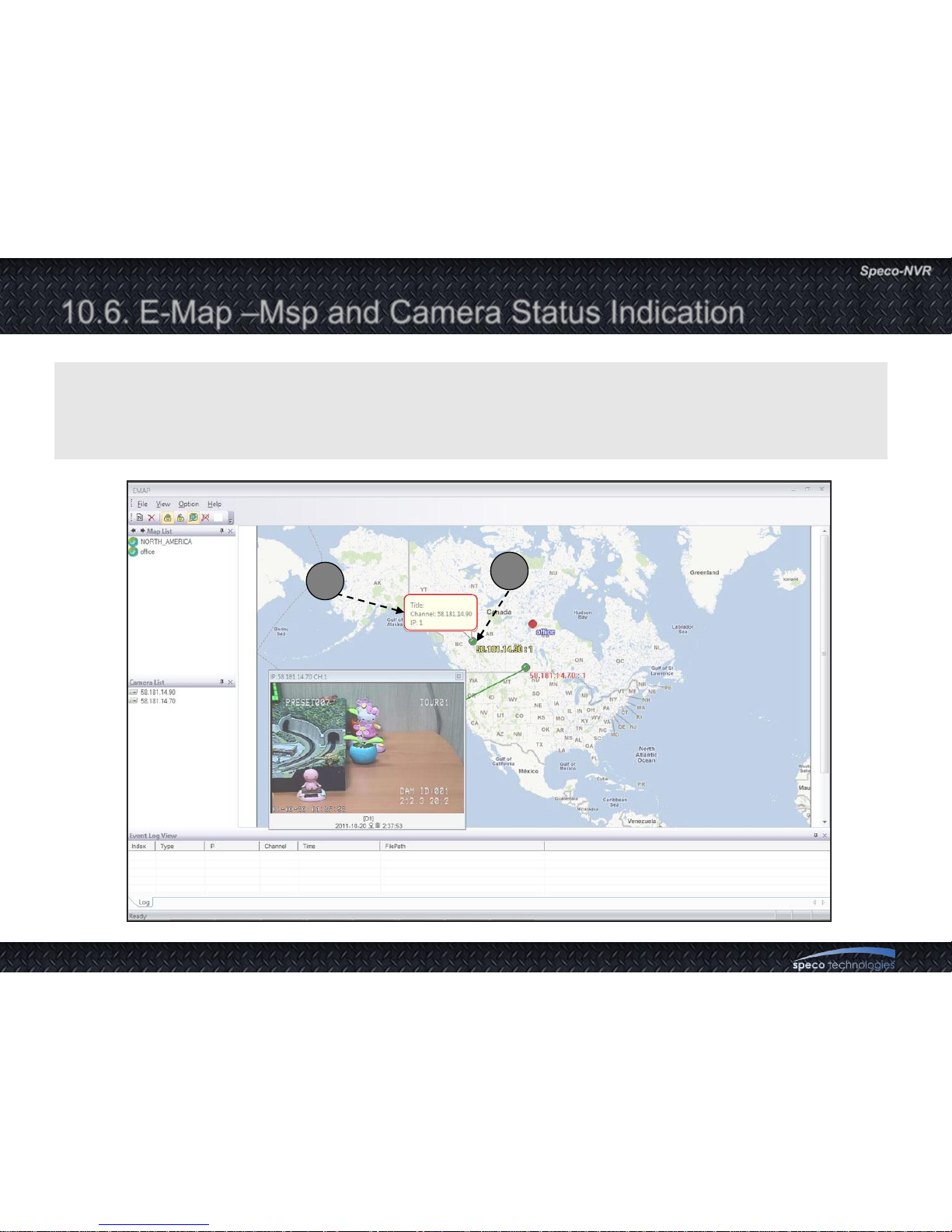
1. Camera status : Dark Green circle indicates a camera not connected. Bright green circle
indicates a camera connected.
2. Information Display : Locate the cursor on top of the Icon to show the address, channel and
description of the camera.
1
2
Page 70
User Guide Rev 1.0
Page 70
10.7. E-Map – Connection to the Camera for Live View
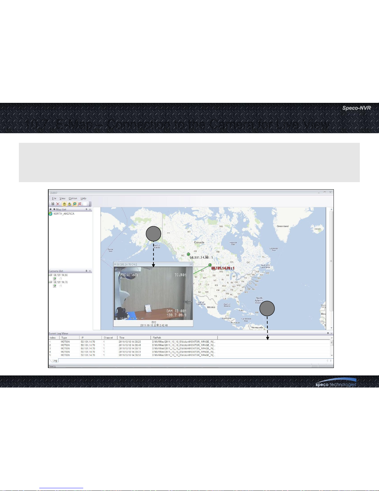
1. Pop-up menu : Clink on the right button after placing the cursor on the Camera Icon for the pop-up
menu.
2. Live Pop-up : Double click the Camera Icon or select View from the pop up menu to show live
streaming data from the camera.
2
1
Page 71
User Guide Rev 1.0
Page 71
10.8. E-Map – Event Display
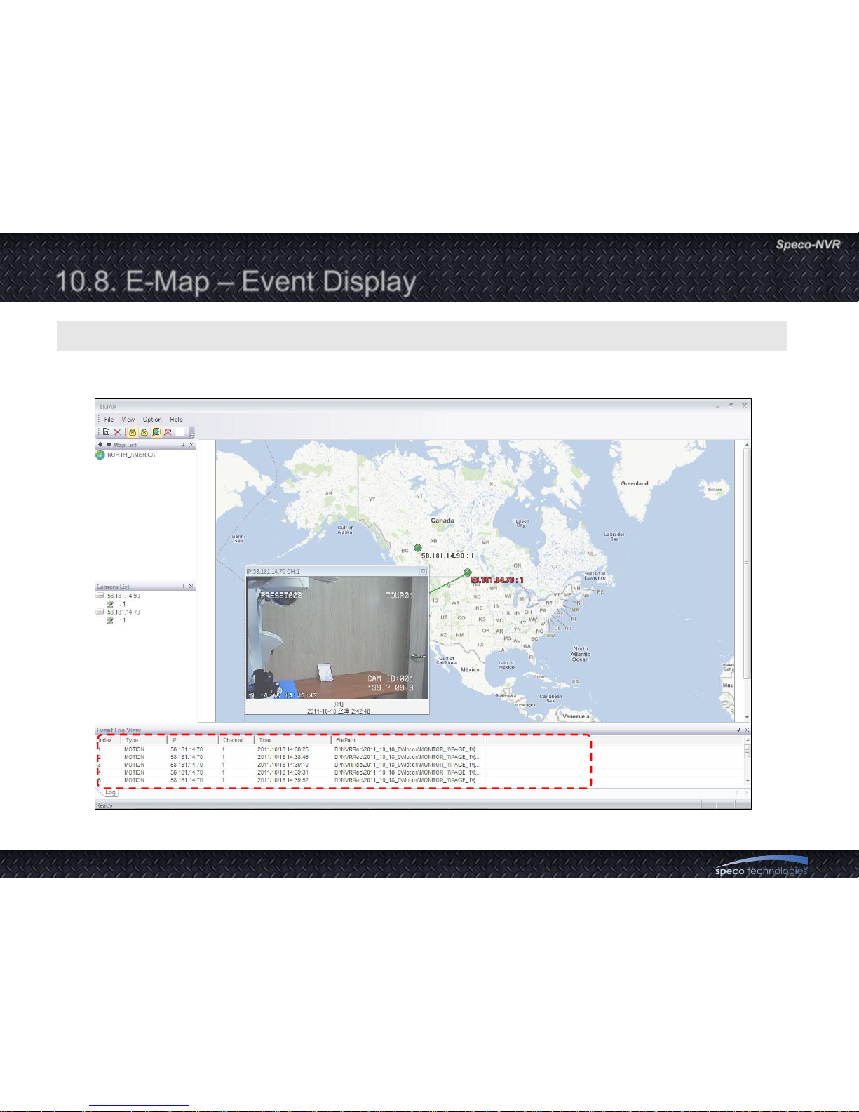
The list of events are displayed in this window.
Page 72
User Guide Rev 1.0
Page 72
10.8. E-Map – Event Display
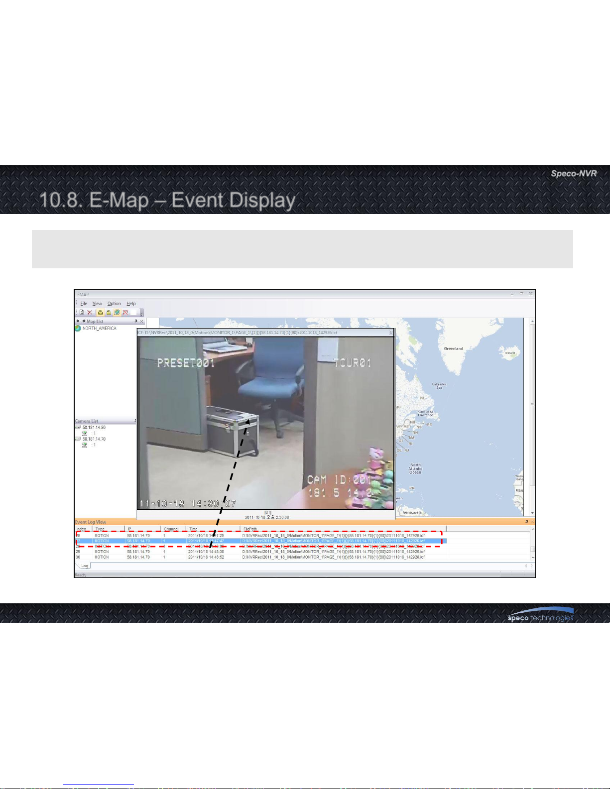
1.Double click on the file path to playback the alarm event on a pop-up window
2.Up to 1000 events are stored and the oldest event will be removed to record new event.
Page 73
User Guide Rev 1.0
Page 73
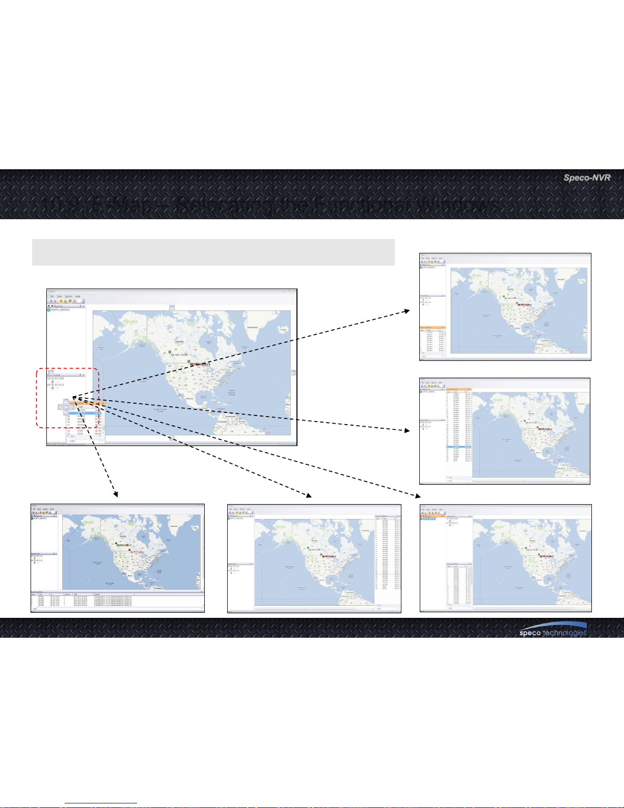
10.9. E-Map – Relocating the Functional Windows
Use Drag & Drop for relocating the functional windows
Page 74
User Guide Rev 1.0
Page 74
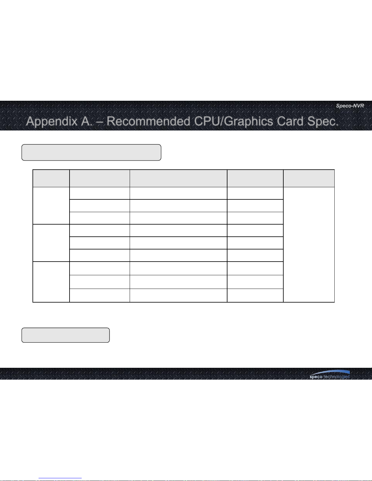
Appendix A. – Recommended CPU/Graphics Card Spec.
Use Graphics Card which is based on ATI Radeon Chipset
CPU
Graphics Card
CPU Resolution Video rate / frame rate Max Ch RAM
i7 2600
1600x1200 4M / 15fps 16
4GByte or
Above
1280x720 3M / 30fps 20
704x480 1M / 30fps 64
i5 2500
1600x1200 4M / 15fps 12
1280x720 3M / 30fps 16
704x480 1M / 20fps 64
i3 2100
1600x1200 4M / 15fps 8
1280x720 3M / 30fps 11
704x480 1M / 30fps 32
Page 75
User Guide Rev 1.0
Page 75
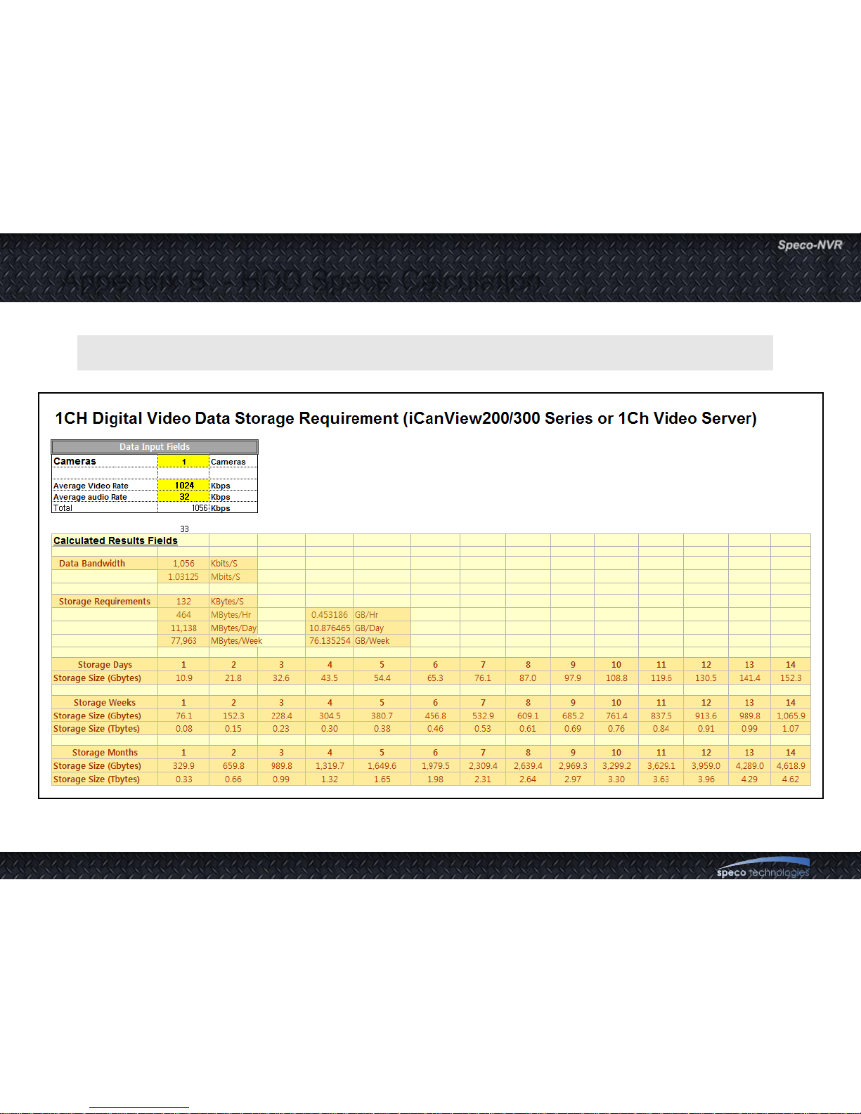
Appendix B. - HDD Space Calculation
Use storage calculator in selection guide for calculation of the space.
Page 76
User Guide Rev 1.0
Page 76
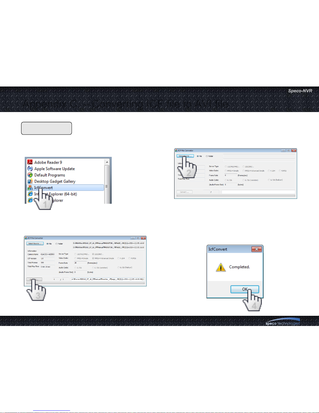
Procedure
1. Click START and Run IcfConverter
from program menu.
2. Click „Select Source‟ and select ICF format file.
3. Click „Convert‟ button to convert file format to AVI.
4. When the converting is complete, a window
pops up. Click OK and check the converted
AVI file.
Appendix C. – Converting ICF file to AVI file
3
2
1
4
 Loading...