

Page 1
INSTRUCTION MANUAL
FOR ASSISTANCE OR REPAIR SERVICE CONTACT:
200 New Highway, Amityville, NY 11701-0726
631-957-8700 • Toll Free: 1-800-645-5516
Speco Technologies is constantly developing and improving products.
We reserve the right to modify product design and specifications without
notice and without incurring any obligation. Rev. 4.4.12.
www.specotech.com
We are not responsible for typographical errors.
C
2012 Speco Technologies All rights reserved.
MIC-1
Min MaxMin Max
PRIORITY
I/O
MIC-2
Min MaxMin Max
-60dB
1mV
AUX
Min MaxMin Max
-10dB
100mV
BASS
-10 dB +10 d B-10 dB +10 d B
TREBLE
-10 dB +10 d B-10 dB +10 d B
PVL-15A/30A
PUBLIC ADDRESS
AMPLIFIER
15/30 WATTS RMS
POWER
I
O
Page 2
PVL-15A. 30A PVL-15A. 30A
1
14
Page 3
PROFESSIONAL SERIES AMPLIFIER
MIC-1
Min MaxMin Max
PRIORITY
I/O
MIC-2
Min MaxMin Max
-60dB
1mV
AUX
Min MaxMin Max
-10dB
100mV
BASS
-10 dB +10 d B-10 dB +10 d B
TREBLE
-10 dB +10 d B-10 dB +10 d B
POWER
I
O
PVL-15A, 30A
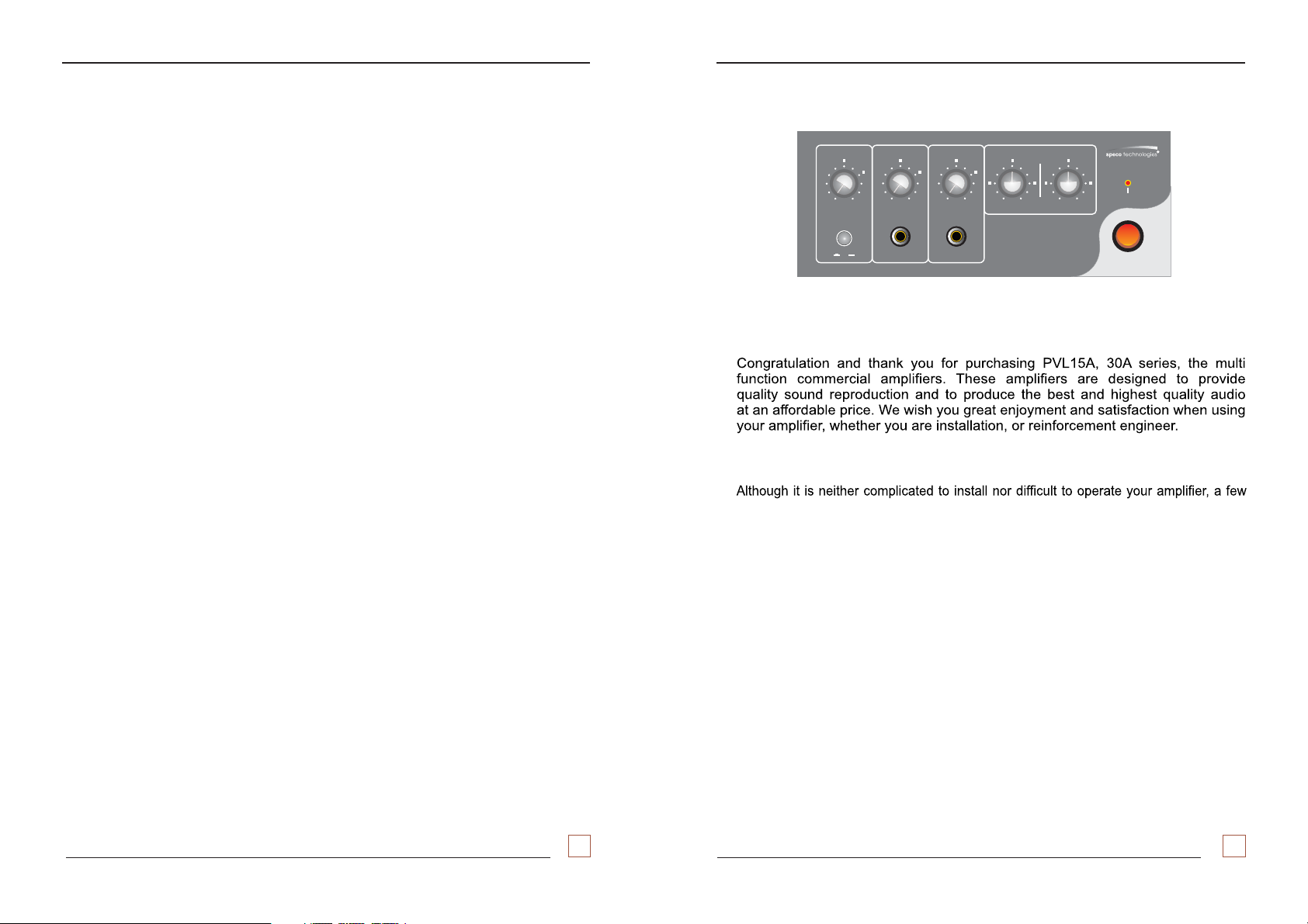
Welcome
Unpacking and Installation
minutes of your time is
and familiarity with its
required to read this manual for a properly wired installation
many features.
Please take great care in unpacking your
amplifier and do not discard the carton or other packing materials. These may
be needed when moving your amplifier and are required if it ever becomes
necessary return your amplifier for service. Never place the unit near radiators, in front
of heating vents, in direct sunlight, or in excessively humid or dusty location to avoid damage.
Connect your complementary components as illustrated in the following page.
Packing List
The unit was carefully checked before leaving the factory.
The Professional Series carton contains the following components:
1 - Professional Series unit
1 - User Manual
PVL-15A. 30A PVL-15A. 30A
13
2
Page 4

SERVICE AND MAINTEANCE
SPECIFICATIONS
The use of solid state circuitry and advanced manufacturing technigues
built in your unit results in very high reliability, and under normal operat
- ing conditions, your amplifier should not require service other than an
occasional external cleaning.
Keep the original carton and packing material to use if you need to
return your unit for service. Merchandise to be returned for out- ofwarranty or in- warranty repair requires prior written authorization.
Please write or call toll free 1-800-645-5516 or in METRO NEW YORK
631- 957- 8700. We request you enclose a packing slip with the shipment
that has a complete description of the problem and dated proof of
purchase, if in warranty. when shipping the unit to the factory, please
be sure to pack the unit well enough to withstand rough handling and
use return shipping label supplied by peco techologes. Ship the unitS
FREIGHT PREPAID, TO :
200 NEW HIGHWA Y - P . O. BOX 726
AMITYVILLE, NEW YORK 11701- 0726
When ordering parts,please give a description or the part number, if
available. Direct your order to the PARTS DEPARTMENT.
We will then advise total c ost for remittance including shipping and
handling.
RMS POWER OUTPUT ............................. Watts @1% THD15/30
MAX 30/60POWER OUTPUT ............................. Watts
RMS POWER BANDWIDTH ....................... 30Hz to 20KHz, +/-3dB
FREQUENCY RESPONSE (RMS )POWER 30Hz to 20KHz, -3dB/-1dB
()Aux Input
INPUT SENSITIVITY
Mic. 1, ............................................. 2.45mV -50dB 600 BALV
Mic. 2. ............................................. 2.45mV -50dB 600 BALV
Aux. , ............................................. 245mV -10dB 10K UNBAL1 V
HUM & NOISE
Mic. 1. .............................................. 7 dB (Balanced)5
Mic. 2. .................................................. 75dB (Balanced)
Aux. 1, .............................................. 80dB (Unbalanced)
TONE CONTROL ....................................... +/- 10dB Bass, Treble.
SPEAKER OUTPUT ................................... 4, 8 ohms,
25V and 70V
AC SUPPLY VOLTAGE ............................... 120V AC 50/6Hz
AC POWER CONSUMPTION
Stand- by ........................................... 10 Watts
@Max. RMS Output ............................... 00 Watts60/1
Speco technologies
200 New Highway P.O. Box 726
Amityville, N.Y. 11701-0726
U.S.A.
TEL : 631-957-8700, 1-800-645-5516
www.specotech.com
CONTROLS ............................................... 2 Mic. Vol.
1 Aux. Vol.
1 Piority push switch.
2 Tone Control
1 Power on/ off switc h
DIMENSION (H x W x D) ..........................
78mm x 200mm x 210mm
3” x 7 3/ 2” x 7 3/3”
WEIGHT ................................................... 3.8Kg / 4.8Kg (8.4 lb/10.6 lb)
NOTE ; Specifications and design subject to change without notice.
PVL-15A. 30A PVL-15A. 30A
3
12
Page 5

CONNECTIONS
MIC
DESCRIPTION
The P - 30A is a rugged, dependable,VL 15/ 15W/30W public address amplifier
This unit contains features generally found in much higher priced models
and can be used with virtually any program source.
2 microphone inputs. The 2 microphone inputs may be
ON
impedance microphone. HI- Z microphone (over 1k ohm)
operation LO- Z microphone (up to 600 ohm)Wireing
balanced or unbalanced.
Mic-1 may be use for priority paging. The unit hasinput
AUX input for use with radio tuners, tape decks or other high impedance, high output
devices. The inputs are controlled by their individual
Outputs are provided for 4 and 8 ohms speakers and 25V and 70V constant
voltage lines.
The P - 30A featureVL 15/
used for high or low
input is for unbalanced
input may be operated
volume controls.
BALANCED OUTPUT POWER RMS 30WBALANCED OUTPUT POWER RMS 30W
COM 4 8 25V 70VVV
COM 4 8 25V 70VVV
11V 15.5V 20.8 163.3VV
11V 15.5V 20.8 163.3VV
FUSE T 1.0 AL 250V
0 3051930519 27240 7
SPEAKER
AUX INPUT
R
L
RCA INPUT
RCA INPUT
UNBALANCED INPUT
UNBALANCED INPUT
-10dB (245mV) 10KV
CAUTION
RISK OF ELECTRIC SHOCKRISK OF ELECTRIC SHOCK
DO NOT OPEN
-10dB (245mV) 10KV
P
-
SERIES P.A. AMPLIFIER PVL30A
P
-
SERIES P.A. AMPLIFIER PVL30A
ASSISTANT INPUT SYSTEM
MC-5650 6 CHANNEL POWER AMPLIFIERMC-5650 6 CHANNEL POWER AMPLIFIER
PEAK LEVEL
PEAK LEVEL
-40dB
-40dB
CH-1 CH-2 CH-3 CH-4 CH-5 CH-6CH-1 CH-2 CH-3 CH-4 CH-5 CH-6
POWER
POWER
AUTO MONITOR SCREEN PANELAUTO MONITOR SCREEN PANEL
FM/AMDIGITALTUNER P-FA
FM-1
PLL FREQUENCY SYNTHESIZER
11
BAND SEEK SEEK
UP MEMORY
DOWN
Mz
MEMO 3
MEMO 5 MEMO 6
MEMO 1 MEMO 2
MEMO 4
CD-600R 6CD PLAYER RECEIVER
OPEN
OPEN
DISC
UP
12 TRACK
SCANSCAN
UP
DOWN
DOWN
FM/AM TUNER & CD DECK P-FA. CD-600R
BALANCED MIC INPUT 1;
BALANCED MIC INPUT 1;
-60dB (2.45mV) 600 BALV
-60dB (2.45mV) 600 BALV
1-GND 2- HOT 3- COLD1-GND 2- HOT 3- COLD
PEAK LEVEL
PEAK LEVEL
PROT-A
P-60,100,150, 250A/Az/AQ/AQz
VOLUME
Min Max
FM-1
PWR
PLAY/PLAY/
MEMO 1 MEMO 2MEMO 2
REPEAT
MIC-1 INPUT
CONTROLS
FRONT PANEL CONTROLS
X LR INPUT
X LR INPUT
1-GND
1-GND
BALANCED MIC INPUT 1;
BALANCED MIC INPUT 1;
2-HOT
2-HOT
-60dB (2.45mV) 600 BALV
-60dB (2.45mV) 600 BALV
3-COLD
3-COLD
www.specotech.com
MADE IN KOREA
-40dB
-40dB
PROT-B
PROT-B
POWER
18
LEVEL METER
POWER
POW1020406080100%
-241816126303dB+
POWER
FM/AM DIGITAL TUNERFM/AM DIGITAL TUNER
I/O
UP
DOWN
M 6
MEMO 3
MEMO 5
MEMO 6MEMO 6
MEMO 4MEMO 4
MEMORY
REEL DECK
a. The POWER SWITCH :
The Power switch is located at the extreme right hand side of the front panel
When switching the amplifier on, the red switch will become illuminated
b. MICROPHONE VOLUME CONTROL :
Rotating the microphone c ontrols
clockwise increases the gain of the
microphone inputs.
c . AUX VOLUME CONTROL :
Rotating the AUX controls cloc kwise
increases the gain of the AUX input.
e. TONE CONTROL :
Rotating the Tone control clockwise increases the
Bass/Treble and
counter B /Treble .clockwise increase the ass Tone is flat at center.
PVL-15A. 30A PVL-15A. 30A
11
4
Page 6

CONTROLS
1. FRONT PANEL CONTROLS
23451
MIC-1
Min MaxMin Max
PRIORITY
I/O
MIC-2
Min MaxMin Max
-60dB
AUX
BASS
TREBLE
Min Max
-10 dB +10 dB-10 dB +10 dB
-10dB
100mV
1mV
-10 dB +10 dB-10 dB +10 dB
POWER
I
O
67 8 1
1. POWER SWITCH
When powering the amplifier on, the switch will illuminate.
2. MIC VOLUME CONTROL
Rotating the microphone c ontrols
clockwise increases the gain of the
microphone inputs.
3. AUX VOLUME CONTROL
Rotating the AUX controls cloc kwise
increases the gain of the AUX input.
4. BASS CONTROL
This control is used for adjusting +/- 10db low frequency sound(100Hz)
5. TREBLE CONTROL
This control is used for adjusting +/- 10db high frequency sound(10KHz)
Input to Mic 1 will automatically ac tivate the priority circuit which temporarily
mutes signals from other inputs, tuner or tape.
1. POWER :
The P A Amplifier is to be operated fromLV-15/30 a AC120V 50/60Hz Power
source. The power required for this amplifier is c learly indicated on the
back panel.
2. INPUT CONNECTIONS :
Make connections to the microphone (high or low impedance) and
auxiliary inputs with the POWER SWITCH in the OFF position and set
corresponding volume control to zero to avoid damage to the speakers
and the amplifier from hum pickup. (Feedback)
a. MICROPHONE CONNECTIONS :
A Switch craft type A3M Microphone connector or equivalent is
required for making connections to the Microphone inputs and audio
shielded cable is required for all balanced and unbalanc ed microphone
input connections.
BALANCED MICROPHONE INPUT CONNECTIONS(MIC. 1 only) :/2
Using 2 conductor shielded cable, connect each of the two center
conductors of the cable to prongs # and of the A3M Microphone1#2
connector. Connec t the shield of the cable to prong # 1 of the A3M
Microphone connector.
UNBAL ANCED MIC ROPHONE INPUT CONNECTIONS (MIC. # 1 & # 2) :
Using single conductor shielded cable,connect the center c onductor
of the cable to prong # 2 of the A3M Microphone connec tor.
Connect the shield of the cable to prong # 1 of the A3M Microphone
connector.
7. MIC-2 INPUT
LO-Z Balanced type 2.45mV/600V
HI-Z Unbalanced type 245mV/10KV
b. AUXILIARY INPUTS :
The auxiliary input receptacles and all other
phono input require an 1/4”
Type phono plug
(Cinch- jones # 13A) or equivalent.
PVL-15A. 30A PVL-15A. 30A
5
10
Page 7

INSTALLATION OF SPEAKERS
MODE L 4 OHM 8O HM 2 5V 7 0V
PVL15A 7.7V 11V 41.7 OHM 327 OHM
CONTROLS
1. BACK PANEL CONTROLS
4 35
PVL30A 11V 15.5V 21 OHM 163 OHM
Installation of the Speaker
When you connect the speaker, remove the AC cord from AC OUTLETS then connect the speakers
as described below, after selecting the suitable terminal.
FOR LOW IMPEDANCE WIRING
COM 4 8 25V 70VVV
4 OHM
4 OHM
COM 4 8 25V 70VVV
FOR 8OHM LINE
16 OHM 16 OHM
+
8 OHM
+
+
-
-
FOR 70V LINE
+
+
-
-
FOR 4OHM LINE
COM 4 8 25V 70VVV
SPEAKER
OUTPUT
4 OHM 8 OHM 8 OHM
+
+
-
-
4 OHMS WIRING 8 OHMS WIRING
FOR HIGH IMPEDANCE WIRING
FOR 25V LINE
COM 4 8 25V 70VVV
SPEAKER
OUTPUT
+
-
BALANCED OUTPUT POWER RMS 30W
COM 4 8 25V 70VVV
COM 4 8 25V 70VVV
11V 15.5V 20.8 163.3VV
11V 15.5V 20.8 163.3VV
FUSE T 1.0 AL 250V
0 30519 2724027240 7
RISK OF ELECTRIC SHOCKRISK OF ELECTRIC SHOCK
CAUTION
DO NOT OPENDO NOT OPEN
AUX INPUT
R
L
RCA INPUT
RCA INPUT
UNBALANCED INPUT
UNBALANCED INPUT
-10dB (245mV) 10KV
-10dB (245mV) 10KV
P
-
SERIES P.A. AMPLIFIER PVL30A
P
-
SERIES P.A. AMPLIFIER PVL30A
BALANCED MIC INPUT 1;
BALANCED MIC INPUT 1;
-60dB (2.45mV) 600 BALV
-60dB (2.45mV) 600 BALV
1-GND 2- H OT 3- COL D
1-GND
1-GND
2-HOT
2-HOT
3-COLD
3-COLD
1 2
2. FUSE HOLDER
This fuse holder contains the AC power fuse. Replace
type fuse when it is blown. If it
and refer
servicing to qualified personnel.
MODEL PVL-15A PVL-30A
continuously blows, stop replacing fuse
MIC-1 INPUTMIC-1 INPUT
X LR INPUT
X LR INPUT
BALANCED MIC INPUT 1;
BALANCED MIC INPUT 1;
-60dB (2.45mV) 600 BALV
-60dB (2.45mV) 600 BALV
MADE IN KOREA
only with same
SPEAKER
OUTPUT
With
Matching
Trans
SPEAKER
OUTPUT
25V LINE WIRING 70V LINE WIRING
*Be sure that total impedance is not less than rated impedance. (See upper chart.)
5. SPEAKER OUTPUT TERMINALS
With
Matching
Trans
These terminals are for speaker connection. You
8 ohm or higher impedance
total impedance less than rated
lines 25V and 70V Be sure not to make the
impedance on 25V or 70V. 4 ohm and
can select 4 ohm or
8 ohm must be matched exactly.
MODEL 4 OHMS 8 OHMS 25V 70V
PVL-15A 7.7V 11V 41.7 OHM 327 OHM
PVL-30A 11V 15.5V 21 OHM 163 OHM
* Be sure not to make the total impedance less than rated impedance.
PVL-15A. 30A PVL-15A. 30A
9
6
Page 8

WIRING GUIDE
Choose input wire and connectors
HCA recommends using pre-built or professionally wired balanced line, 22 to 24 gauge cables.
Figure shows connector pin assignments for wiring .The RCA input connections can also be
used for unbalanced inputs
XLR BALANCED WIRING GUIDE
Input
For unbalanced use pin 1 and 3 have to be bridged
BALANCED LINE
hot(+ve)
ground
cold(-ve)
MIC INPUT OUTPUT
+
-
UNBALANCED LINE
hot(+ve)
ground
cold(-ve)
+
output
hot(+ve)
ground
cold(-ve)
hot(+ve)
ground
cold(-ve)
Input output pin no:
BALANCED LINE
+
-
UNBALANCED LINE
+
POWER SWITCH
POWER
The POWER switch applies
power to unit.
I
The switch will illuminate
O
LED when power is on.
MAIN POWER SWITCH VOX CONTROLS SWITCH
INDIVIDUAL VOLUME CONTROLS
MIC-2
MIC-1
Min MaxMin Max
Min Max
BAND FREQUENCY TONE CONTROLS
AUX
Min MaxMin Max
FRONT MIC-2 AND AUX INPUT JACK
PRIORITY
-60dB
I/O
1mV
PRIORITY AND MUTING ON/OFF SWITCH
PRIORITY
I/O
Input to Mic-1
on switch will
activate the
priority circuit
Each input is controlled
by an individual volume
control.
MIC AUX VOLUME CONTROLS
P
-
SERIES P.A. AMPLIFIER
P
-
TREBLE
TREBLE
SERIES P.A. AMPLIFIER
PVL30A
PVL30A
POWER
BASS
BASS
-10 dB +10 dB-10 dB +10 d B
-10 dB +10 dB-10 dB +10 d B
-10dB
100mV
These jack(PL-55) are for AUX input.
HI-Z Unbalanced type 245mV/10KV
AUX JACK (PL55 TYPE 1/4”)
-10 dB +10 dB-10 dB +10 d B
-10 dB +10 dB-10 dB +10 d B
MIC INPUT OUTPUT
Balances 1/4” Connector Unbanded 1/4” Connector
PVL-15A. 30A
AUX INPUT
BALANCED MIC INPUT 1;
BALANCED MIC INPUT 1;
-60dB (1mV) 600 BALV
R
L
-60dB (1mV) 600 BALV
1-GND 2- HOT 3- COLD1-GND 2- HOT 3- COLD
SPEAKER OUTPUT TERMINALS
BALANCED OUTPUT POWER RMS 30WBALANCED OUTPUT POWER RMS 30W
COM 4 8 25V 70VVV
COM 4 8 25V 70VVV
MIC-1 INPUT
11V 15.5V 20.8 163.3VV
11V 15.5V 20.8 163.3VV
BACK MIC-2 AND AUX INPUT JACK
RCA INPUT
RCA INPUT
UNBALANCED INPUT
UNBALANCED INPUT
-20dB (245mV) 10KV
-20dB (245mV) 10KV
PVL-15A
COM 4 8 25 V 70V
VV
COM 4 8 25 V 70V
VV
7.7
7.7
V 11V 41 .7 3 27VV
V 11V 41 .7 3 27VV
PVL-30A
COM 4 8 25 V 70VVV
COM 4 8 25 V 70VVV
11V 15.5V 20.8 163.3VV
11V 15.5V 20.8 163.3VV
1-GND
1-GND
2-HOT
2-HOT
3-COLD
3-COLD
X LR INPUT
X LR INPUT
BALANCED MIC INPUT 1;
BALANCED MIC INPUT 1;
-60dB (2.45mV) 600 BALV
-60dB (2.45mV) 600 BALV
FUSE T 1.0 AL 250VFUSE T 1.0 AL 250V
FUSE
0 30519 27240 7
RISK OF ELECTRIC SHOCK
CAUTION
DO NOT OPEN
POWER CORD AND FUSE
7
PVL-15A. 30A
8
 Loading...