

Page 1

P32S36GM Configuration Guide
1
P32S36GM Configuration Guide
The$software$version$corr esponding$to$this$manual:$Release$4.0.x$
$
$
Document$version$number:$V1.08$
$
$
Post$date:$12.18.2020$
! !
Page 2

P32S36GM Configuration Guide
2
Content
1 Overview ............................................................................................................................................ 4
1.1 Introduction .............................................................................................................................. 4
1.2 Login to the Web Administrator ................................................................................................. 4
1.3 Equipment Overview ................................................................................................................ 5
1.4 Exit Web Administrator ............................................................................................................. 6
1.5 Save Configuration ................................................................................................................... 7
1.6 Introduction to Web Management Page Layout ........................................................................ 7
1.7 Introduction to Web Management Functions ............................................................................. 8
2 Interface ........................................................................................................................................... 12
2.1 Port Management ................................................................................................................... 12
2.2 Port Speed Limit ..................................................................................................................... 15
2.3 Storm Control ......................................................................................................................... 20
2.4 Port Statistics ......................................................................................................................... 23
2.5 Port Mirroring ......................................................................................................................... 24
2.6 Port Isolation .......................................................................................................................... 26
2.7 Port Aggregation .................................................................................................................... 27
2.7.1 Overview .......................................................................................................................... 27
2.7.2 Configure Aggregation Port .............................................................................................. 29
2.7.3 Configuration Examples ................................................................................................... 31
2.8 Management of PoE ............................................................................................................... 33
3 Exchange ......................................................................................................................................... 36
3.1 A VLAN .................................................................................................................................. 36
3.1.1 Overview .......................................................................................................................... 36
3.1.2 Link Type ......................................................................................................................... 36
3.1.3 Default VLAN (PVID) ...................................................................................................... 37
3.1.4 Configuration VLAN ......................................................................................................... 38
3.1.5 VLAN Configuration Example ........................................................................................... 41
3.2 ERPS ..................................................................................................................................... 44
3.5 MAC Management ............................................................................................................... 84
3.5.1 Overview ......................................................................................................................... 84
3.5.2 Configure the MAC address .......................................................................................... 86
3.5.3 MAC Address Configuration Example .......................................................................... 87
3.6 QinQ ...................................................................................................................................... 88
3.6.1 Overview ......................................................................................................................... 88
3.6.2 QinQ Configuration ....................................................................................................... 90
3.6.3 QinQ Configuration Example ............................................................................................ 91
4 Safety ............................................................................................................................................... 97
Page 3

P32S36GM Configuration Guide
3
4.1 ACL ........................................................................................................................................ 97
4.2 QoS ...................................................................................................................................... 103
4.3 DHCP Snooping.................................................................................................................. 110
4.4 802.1 X authentication ....................................................................................................... 111
4.5 MAC Authentication........................................................................................................... 120
4.6 The RADIUS ......................................................................................................................... 123
5 System ........................................................................................................................................... 130
5.1 Manage IP Addresses .......................................................................................................... 130
5.2 User Management ................................................................................................................ 136
5.3 Services ............................................................................................................................... 137
5.4 The SNMP ............................................................................................................................ 138
5.5 Date/Time ............................................................................................................................. 145
5.6 Profile Management .............................................................................................................. 147
5.7 System Upgrade ................................................................................................................... 148
5.8 Log/Diagnosis ....................................................................................................................... 149
5.9 Restart ................................................................................................................................. 150
6 The Routing .................................................................................................................................... 151
6.1 The Routing .......................................................................................................................... 151
6.2 Management of ARP ............................................................................................................ 158
7 Diagnosis ....................................................................................................................................... 163
7.1 Network Tools ...................................................................................................................... 163
7.2 Dying Gasp........................................................................................................................... 165
7.3 Optical Transceiver Information ............................................................................................ 165
Page 4

P32S36GM Configuration Guide
4
1 Overview
1.1 Introduction
In order to facilitate the operation and maintenance of network equipment by network administrators, our
company has introduced the web management function in the P32S36GM. The administrator can use the
web interface to intuitively manage and maintain the unit. The operating environment of the web network
management system is shown in Figure 1-1.
Figure 1-1 Web Management Operating Environment
1.2 Login into the Web Administrator
The user needs to use the default account when logging into the Web administrator for the first time.
After logging in, in order to ensure the safety of the device, the password needs to be changed
immediately. The specific steps are as follows:
•
Log in to webmaster using the default account
•
Change user password
When the device leaves the factory, Web server service has been enabled by default, and it has a
default login account: user name is admin, login password is admin, and IP address is 192.168.56.166.
Users can use this information to complete their first Web administrator login.
Take a 4GX8GT switch as an example to introduce how to log into the device via Web. The specific steps
are as follows:
(1)
Connect the device to a PC via the Ethernet port on the device (all ports belong to VLAN 1 by default)
with a network cable.
(2)
Configure the IP address for PC, and set the IP address of PC in the same network segment as the
default VLAN interface IP address of the device (in addition to the default IP address of the device), such
as 192.168.56.120.
(3)
Launch the browser and enter your login information.
Figure 1-2 Web login interface
Page 5

P32S36GM Configuration Guide
5
Start the browser on the PC, enter "192.168.56.166" in the address bar and enter the Web login page of
the device, as shown in figure 1-2. Enter the default account "admin" and password "admin", and click the
"login" button to log in to the Web administrator. The system will automatically select the language
according to the operating system language used by the user, and the user can also manually switch
(including Chinese and English).
(1)
For the built-in browser of Windows, Edge is recommended and IE6 is not supported.
(2)
For optimal performance, it is recommended to use the Google browser, or 360 or Baidu browser, as
shown in figure 1-3
Figure 1-3 360 safe browser
1.3 Equipment Overview
As shown in figure 1-5, click "overview" in the menu to enter the general system information page. On
this page, MAC address, product serial number, software and hardware version, system running state
and other information of the device can be viewed. Specific parameters are shown in table 1-1.
Figure 1-5 basic information of the system
Page 6

P32S36GM Configuration Guide
6
Configuration Items
Instructions
The Host Name
A device's electronic tag, used by the user to identify the host, can only be numeric, alphanumeric, or
alphanumeric combination
The MAC Address
Used to indicate the MAC address of the device
Hardware Version
Used to indicate the hardware version number of the device
Software Version
Software version number used to indicate the device
Release Time
Used to indicate when the software version of the device will be released
Product Serial
Number
To indicate the product serial number of the device
CPU
To display the current CPU utilization
Available Memory
(KB)
Used to display the current system available memory
The Elapsed
Time
Used to indicate the continuous running time of the device after the last startup, and the time
will be restarted after the restart of the device
Table 1-1 basic information parameter description
1.4 Exit the Web Administrator
•
The system does not automatically save the current configuration when exiting webmaster. It is recommended that
users save the current configuration before exiting webmaster.
Page 7

P32S36GM Configuration Guide
7
Configuration Items
Instructions
Product Model
Used to display the product model
The Navigation Bar
Organize the Web network management function menu of the device in the form of navigation tree.
Users can choose the function menu conveniently in the menu The selection results are
displayed in the configuration area
Language Selection
For switching languages, currently only Chinese and English are supported
The Configuration Area
An area for users to configure and view
Operation steps:
Click the "logout" button below the navigation bar on the Web administrator page (as shown in figure 1-6)
to exit the Web administrator.
1.5 Save Configuration
•
After configuring all projects on the page, be sure to save the configuration, otherwise unsaved configuration information will
be lost due to restart and other operations.
Operation steps:
Click the "save" button below the navigation bar on the Web administrator page (as shown in figure 1-6)
to save the current configuration to the configuration file. The configuration is still valid after restart or
power-down restart.
There are two ways to save a configuration:
(1)
In the current configuration interface, click "ok" or "apply" button to save the current configuration into
memory. Saving at this time does not really save the configuration items into the configuration file. If the
switch has a power failure or other failures at this time, the configuration of the interface will fail.
(2)
Click the "save" button below the navigation bar, and the system will automatically save the
configuration of all pages to the configuration file.
1.6 Introduction to Web Management Page Layout
As shown in figure 1-6, the main page of Web management is divided into four parts: product model,
navigation bar, language selection button, and configuration area. Function description of each part is
shown in table 1-2.
Table 1-2 Web layout instructions
Page 8

P32S36GM Configuration Guide
8
(1) Product Model
(2) Navigation Bar
(3) Language Selection
(4) Configuration Area
Menu/Tab
Functional Explanation
Overview
Basic information
Displays the device's MAC address, serial number,
hardware and software version, and sets the device's
electronics Tags, CPU usage, elapsed time, etc
Port
Port management
Displays information about all ports and sets the
various features of the ports
Port speed limit
Show/set port speed limit
Storm control
Show/set the suppression ratio for broadcast, multicast,
and unknown list play ports
Port statistical
Display, query, and clear interface statistics
Port mirror
Show/set/delete the mirror of the port
Port isolation
Show/set/remove port isolation
Port
aggregation
Overall
configuration
Show/configure an algorithm for port aggregation
Aggregation
port
Displays information about the aggregation interface,
as well as information about the port members in the
aggregation interface
Aggregate
member port
Configure the aggregation port ID to which the
member port belongs, working mode
PoE
management
PoE Overall
Configuration
Display/configure PoE power supply in non-standard
mode
PoE Interface
configuration
Show/configure PD devices that PSE hangs
Figure 1-6 Web administration home page
1.7 Introduction to Web Management Functions
The specific description of Web network management function is shown in table 1-3.
Table 1-3 Web management function description
Page 9

P32S36GM Configuration Guide
9
Exchange
VLAN
VLAN
Create, modify, and delete vlans
Interface
Display port status, configure port
properties, VLAN ownership
ERPS
Overall situation
Shows the status of ERPS, previous event,
ring number, east interface, west interface,
etc.
Configuration
Ring
configuration
Configure the ERPS ring number, east
interface, west interface
Instance
configuration
Configure blocking points of ERPS,
manage VLAN, data VLAN, etc
IGMP
Snooping
IGMP Snooping
Turn on/off the IGMP Snooping function
IGMP routing mouth
Show/configure IGMP routing ports
IGMP static group
Display/configure IGMP static groups
Spanning tree
Overall situation
Displays the MSTP port parameters
Global configuration
Display and set MSTP global parameters
The MST configuration
Display MSTP field information, modify
the MSTP field
The instance
Create/delete MSTP instances
Interface
Display and set MSTP port parameters
MAC
management
MAC management
Set the aging time for MAC addresses
Static address
Configure static MAC addresses without
aging table entries
Filter addresses
Used to discard packets containing a
specific MAC address
Page 10

P32S36GM Configuration Guide
10
Security
The ACL
The ACL
Create, modify, and delete vlans
Application
Display port status, configure port properties, VLAN
ownership
QoS
Overall situation
Display/configure QoS, queue weights
Port trust
Show/configure QoS port trust
CoS mapping
Display/configure QoS CoS mapping
DSCP mapping
Display/configure QoS DSCP mapping
Strategy
Display/configure QoS policies
DHCP Snooping
Disable/enable
Enable/disable this feature
Trust in the
mouth
Set the trust port for DHCP Snooping
802.1 X
authentication
General Situation
Display 802.1x authentication profile
configuration
The configuration of 802.1 X
MAC
authentication
General situation
Displays a MAC authentication profile
configuration
Configure MAC authentication
The RADIUS
Global
configuration
RADIUS global configuration
The server
Show/configure RADIUS server configuration
Page 11

P32S36GM Configuration Guide
11
System
Manage IP addresses
Set the administrative IP address of the device
User management
Set user password
Telnet server
Turn on/off the Telnet server
SNMP
SNMPv1 /v2c
Configuration SNMPv1 / v2c
SNMPv3
Configuration SNMPv3
Date and time
Displays/sets the current system date and time
Profile
management
Download the
back up
Setup to back up configuration files to localhost
Restore
the back up
Set up a local restore profile to the device
factory
Data reset
Settings to restore the device to its factory
configuration
System upgrade
Set up upload upgrade file from local host to upgrade
system software
Log/diagnosis
Generate a diagnostic information file and open it
for viewing or saving on the localhost
Restart
Set up the reboot device
The diagnosis
Web tools
Perform the ping/trace route operation and
display the results
Dying -- Gasp
Turn on/off the gas gasp alert
Optical module information
View optical module information, such as
manufacturer information, serial number, optical
power, etc
Save
\
Save the currently set parameters to ensure the
restart is valid
Cancellation
\
Log out
Page 12

P32S36GM Configuration Guide
12
2 Interface
2.1 Port Management
•
Due to the different parameters of electrical port and optical port, it is recommended to configure electrical port and optical
port separately when selecting multi-port configuration.
The port management module is used to configure and view the working parameters of the Ethernet
interface, including: name, description, port mode, media type, rate, duplex state, flow control, MTU, state,
as shown in figure 2-1.
Figure 2-1 interface management interface
Operation steps:
(1)
Select [interface] [port management] in the menu, as shown in figure 2-1.à
(2)
Check the ports to be configured (support multiple ports) and click the "edit" button to enter the
page as shown in picture 2-2.
(3)
Configure the working parameters of the port, as shown in table 2-1.
(4)
Click the "apply" button to complete the operation.
(5)
Click the "save" button in the menu to save the configuration.
Figure 2-2 interface configuration interface
Table 2-1 interface working parameters description
Page 13

P32S36GM Configuration Guide
13
Configuration Items
Instructions
Describe
Set the description information for the port, using a combination of letters and Numbers.
Medium Type
Configure the media type of the multiplexing port, which is only valid for ports that support
photoelectric multiplexing (Combo).
•
RJ45: set the port to work in port mode.
•
SFP: set the port to work in port mode.
Rate
Set the rate of the port
•
10 m: 10 MBPS
•
M: 100 100 MBPS
•
M: 1000 1000 MBPS
•
AUTO: automatically negotiates port rates
Duplex State
Sets the duplex state of the port
•
AUTO: self-negotiating duplex
•
FULL duplex
•
Sheldon: HALF duplex
Port Mode
Set the working mode of the port to support different working modes, which need corresponding
optical module support.
•
100base-fx: set the port to work in 100 MB light mode.
•
1000base-x: set the port to work in gigabit light mode.
•
SGMII: set the port to work in SGMII mode, which needs to be configured when the optical port
inserts gigabit to 100 MBPS (SFP ge-fx) or light-to-electricity (mini-gbic-gt) modules.
•
2500base-x: set the port to work in 2.5g optical port mode.
•
10G base-x: set the port to work in 10G optical port mode.
•
2500base-x mode, there may be incompatibility with port interconnection of other manufacturers.
•
The optical port capability of different types of equipment is different, please refer to the specification
document corresponding to the specific product model.
•
This feature is only supported by optical ports
Flow Control
Set Enable or Disable port traffic control functions
When this end and the end of the device can enable the flow control function, if the end of the
device congestion, send a message to the end of the device, notify the end of the device to
temporarily stop sending messages;After receiving the message, the opposite device will
temporarily stop sending the message to the opposite device. And vice versa. Thus, packet loss
is avoided
Flow control can be realized only when the flow control function is turned on at both the local port and
the opposite port
Page 14

P32S36GM Configuration Guide
14
MTU
Set the frame length allowed for forwarding from 64 to 10240 bytes. The default is 1526 bytes.
Manage State
Set the open/closed state of the port.
•
Shutdown: the port setting is working normally.
•
Shutdown: setting up the port is in the Shutdown state.
Configuration examples:
Case requirements: configure port eth0/9 to work in 2.5g mode, turn off flow control, set MTU to 10000
bytes, and port description to ABC.
Step 1: select "interface" and "port management" in the menu to enter the port management interface.
Step 2: select port eth0/9 and click the "edit" button to enter the port configuration interface, as shown in figure
2-3.
Step 3: as shown in figure 2-3, follow the description of "ABC", medium type "SFP", port mode "2500base-
x", flow control "OFF", MTU "10000", management state "No shutdown", and configure parameters.
Figure 2-3 interface configuration example
Step 4: click the apply button to complete the operation.
Step 5: click the "save" button in the menu to save the configuration.
Page 15

P32S36GM Configuration Guide
15
2.2 Port Speed Limit
Port speed limit is a port-based speed limit, which limits the total speed of port input and output messages.
Before the flow is sent from the interface, speed limit is configured on the direction of the
interface to control all outgoing message flow. Before the traffic is received from the interface, the speed limit is
configured in the direction of the interface to control all incoming message traffic.
Operation steps:
(1)
Select [interface] [port speed limit] in the menu and enter the port speed limit configuration interface, as
shown in figure 2-4.à
(2)
For ports that need to be configured with speed limit, enter corresponding values in the dialog box, and
the specific parameters are defined as shown in table 2-2.
(3)
Click the "apply" button on the corresponding port to complete the operation.
(4)
Click the "save" button in the menu to save the configuration.
•
This feature only supports single-port configuration, such as eth0/1, and if parameters are entered on other ports, when
eth0/1's apply button is clicked,
Parameters for other ports are cleared (configuration does not take effect).
Figure 2-4 port speed limit interface
•
Limit values are deterministic, such as 1M, and 1024, but burst values are derived from empirical values. When the burst
The numerical distribution is large, the flow peak is higher, the speed limit is stable, but the average speed may be higher than
the speed limit. When the burst value is small, the flow peak is low and the speed limit is limited
The average speed may be less than the speed limit. It is recommended to configure burst with a value of 4 times limit
and a small value of 16384.
Table 2-2 parameter description
Page 16

P32S36GM Configuration Guide
20
Configuration Items
Instructions
Input Rate (KBPS)
Bandwidth limit per second of input direction (KBits).
Input Burst Flow (KB)
Burst traffic limits in the input direction (Kbytes).
Output Rate (KBPS)
Bandwidth limit per second in the output direction (KBits).
Output Burst Flow (KB)
Output direction burst traffic limit (Kbytes).
Application
Sets the port speed limit function that enables the specified port.
Remove
Clear the dialog box of what has been filled in.
Configuration examples:
Case requirements: suppose the port eth0/1 of the switch is connected to the Internet, the traffic limit at
the port eth0/1 outlet is required, the bandwidth limit is 102400KBits per second, and the burst traffic limit
is 256Kbytes per second.
Step 1: select [interface] [port speed limit] in the menu to enter the port speed limit configuration interface.
Step 2: fill in the corresponding parameter dialog box for port eth0/1, as shown in figure 2-5. Step 3: click the
[apply] button of port eth0/1 to complete the configuration.
Figure 2-5 port speed limit configuration interface
Step 4: click the "save" button in the menu to save the configuration.
2.3 Storm Control
When there is excessive broadcast, multicast or unknown unicast data stream in local area network, the
network performance will decline, or even the phenomenon of network paralysis, called broadcast storm.
Storm control for broadcast and multicast and unicast unknown data flow speed, when the switch port
receives the broadcast and unknown unknown multicast or unicast data flow rate exceeds the bandwidth
set, the device will only be allowed through the data stream set bandwidth, beyond the bandwidth of data
flow will be discarded, so as to avoid excessive flood storms formed in the data stream into the LAN.
Storm control module for setting port suppression ratio for broadcast, multicast, unknown list
broadcast. The storm control mode based on bandwidth percentage is adopted. When the speed of
data stream received by the device port exceeds the set bandwidth, the device will only allow the data
stream passing through the set bandwidth, and the data stream exceeding the set bandwidth will be
discarded until the data stream returns to normal.
Page 17

P32S36GM Configuration Guide
21
Configuration steps:
(1)
Select [interface] [storm control] in the menu and enter the storm control interface, as shown in FIG.
2-6.à
(2)
Check the ports to be configured (support multiple ports) and click [edit] to enter the page shown
in figure 2-7.
(3)
Configure storm suppression types and bandwidth suppression ratios of ports, as shown in table 2-3.
(4)
Click the "apply" button to complete the operation.
(5)
Click the "save" button in the menu to save the configuration.
Figure 2-6 interface of storm control state
Figure 2-7 port configuration interface
Page 18

P32S36GM Configuration Guide
22
Configuration Items
Instructions
Name
Selected port
Type
disabled
Turn this feature off.
broadcast
Turn on the broadcast message storm suppression function to realize the traffic
limit of broadcast message.
multicast
Open unknown group broadcast text storm suppression function, can realize the
unknown group broadcast text traffic Restrictions.
unicast
Open unknown list broadcast text storm suppression function, can realize the
unknown list broadcast text traffic Restrictions.
Multicast and broadcast
Turn on the storm suppression function of group broadcast message
+ broadcast message to realize the unknown group broadcast message and
wide Traffic restrictions for broadcast text.
Unicast and broadcast
Open unknown list broadcast text + broadcast message storm suppression
function, can realize the unknown list broadcast Traffic limits for text and
broadcast messages.
all
Select suppress broadcast, multicast, unknown list broadcast.
Bandwidth ratio ( )
The maximum broadcast traffic allowed as a percentage of the port's transmission
capacity Enter a specific percentage.
Table 2-3 parameter description
Configuration examples:
Case requirements: enable storm control on port eth0/1, and set the suppression ratio of broadcast
messages to 10%.
Step 1: select [interface] [storm control] in the menu to enter the storm control interface.
Step 2: select port eth0/1 and click the "edit" button to enter the configuration screen. Step 3: select
broadcast as type and set the bandwidth ratio to 10, as shown in figure 2-8. Step 4: click the apply
button to complete the operation.
Figure 2-8 storm control configuration interface
Step 5: click the "save" button in the menu to save the configuration.
Page 19

P32S36GM Configuration Guide
23
Configuration Items
Instructions
The name of the
Switch port
Receive a message
All messages received by the interface
Number of bytes
received
The number of bytes of all messages received by the interface
Number of messages
sent
All messages sent by the interface
Number of bytes sent
The number of bytes of all messages sent by an interface
Reception rate (PPS)
Interface receiving rate, unit PPS (bit per second bit/second)
Reception rate (BPS)
Packet Per Second Packet rate received by the interface, BPS (Packet Per Second)
Send rate (PPS)
Interface send rate, unit PPS (bit per second bit/second)
Sending rate (BPS)
Packet Per Second Packet Per Second Packet Packet
remove
Reset message
2.4 Port Statistics
The port statistics function is used to display statistics about the number of messages received and sent
by ports.
(1)
Select [interface] -> [port statistics] in the menu and enter the port statistics page, as shown in
figure 2-9.
(2)
In the page, check the number of messages received and sent by each port of the device, the
number of bytes, and the rate of sending and receiving. The specific parameters are shown in the
table 2 to 4.
Figure 2-9 port statistics page
Table 2-4 port statistical parameter description
Page 20

P32S36GM Configuration Guide
24
2.5 Port Mirroring
SPAN (Local Switched Port Analyzer) is the Local mirror function.The function of SPAN will copy the packet of
the designated port to the destination port. In general, the destination port of SPAN will access data detection
equipment. Users will use these devices to analyze the packet received by the destination port for network
monitoring and troubleshooting, as shown in figure 2-10.
SPAN does not affect the message exchange between the source port and the destination port, but
simply copies a copy of all incoming and outgoing messages from the source port to the destination port.
Messages may be discarded when the mirror traffic of the source port exceeds the destination port
bandwidth, such as when the 100Mbps destination port monitors the traffic of the 1000Mbps source port.
SPAN is based on session management, configuring the source and destination ports of SPAN in the
session. There can be only one destination port in a session, but multiple source ports can be configured
simultaneously.
Figure 2-10 port mirroring
Configuration steps:
(1)
Select [interface] [port mirror] in the menu and enter the page shown in figure 2-11.à
Figure 2-11 port mirroring interface
(2)
Click the "add" button to enter the page as shown in picture 2-12.
Figure 2-12 port mirroring configuration interface
Page 21

P32S36GM Configuration Guide
25
Configuration Items
Instructions
The session
Select the group number of the port mirroring group to configure, and you can create a total
of seven mirroring groups.
Purpose interface
Select mirror destination port, only one destination interface per session is allowed
The source interface
Select mirror source ports to allow multiple source ports to exist simultaneously
(3)
Select the session, destination interface and source interface, and the specific parameters
are described in table 2-5.
(4)
Click the "apply" button to complete the operation.
(5)
Click the "save" button in the menu to save the configuration.
Table 2-5 port mirroring parameters
Configuration examples:
Case requirement: monitoring eth0/1 port and eth0/2 inbound/outbound messages using port eth0/3.
Step 1: select [interface] [port image] in the menu to enter the port image configuration interface.
Step 2: click the "add" button to enter the port image configuration interface.
Step 3: select session 1, as shown in figure 2-13, eth0/3 for the destination interface, eth0/1 and eth0/2 for
the source interface.
Figure 2-13 port mirroring configuration interface
Step 4: click the "apply" button to complete the configuration and automatically return to the port mirroring
interface. You can see the successfully created mirror group 1, as shown in figure 2-14.
Figure 2-14 port mirror display interface
Step 5: click the "save" button in the menu to save the configuration.
Page 22

P32S36GM Configuration Guide
26
2.6 Port Isolation
In order to achieve layer isolation between messages, different ports can be added to different vlans, but
limited VLAN resources will be wasted. The isolation between ports in the same VLAN can be realized by
using the port isolation feature. The user only needs to add ports to the isolation group to realize the two-
layer data isolation between ports in the isolation group. The function of port isolation provides users with
a more secure and flexible networking scheme. The port isolation feature is independent of the VLAN to
which the port belongs. For devices that do not support uplink ports, two-way traffic interchanges between
ports in isolation group and ports outside isolation group.
Configuration steps:
(1)
Select [interface] [port isolation] in the menu to enter the port isolation interface, as shown in figure
2-15.à
(2)
Select the port to be isolated and click the "enable/disable" button.
(3)
Click the "save" button in the menu to save the configuration.
Figure 2-15 port isolation interface
Configuration examples:
Networking requirements, as shown in figure 2-16:
•
The cell User1, User2, and User3 are connected to the Switch ports eth0/2, eth0/3, and
eth0/4, respectively.
•
The device connects to the external network through the eth0/1 port.
•
Eth0/1, eth0/2, eth0/3 and eth0/4 belong to the same VLAN; Realize that cell users User1, User2 and User3
cannot communicate with each other, but can communicate with external network.
Page 23

P32S36GM Configuration Guide
27
Figure 2-16 networking topology
Step 1: select [interface] -> [port isolation] in the menu to enter the port isolation interface.
Step 2: select eth0/2, eth0/3, eth0/4, and click the [disabled] button to enable port isolation, as shown in figure
2-17.
Figure 2-17 port isolation configuration interface
Step 3: click the "save" button in the menu to save the configuration.
2.7 Port Aggregation
2.7.1 Overview
2.7.1.1
Binding multiple physical links together creates a logical link, which we call an aggregate port
(port-channel).This function conforms to ieee802.3ad standard. It can be used to extend link bandwidth
and provide higher connection reliability. It is often used for port connection, as shown in figure 2-18.
Polymerization Mouth
Figure 2-18 port aggregation networking model
Page 24

P32S36GM Configuration Guide
28
The polymerization port has the following characteristics:
(1)
High bandwidth, the total bandwidth of the aggregation port is the sum of the bandwidth of the physical
member ports;
(2)
Support the traffic balancing strategy, according to which traffic can be allocated to each member link;
(3)
Support link backup. When a member link in the aggregation port is disconnected, the system will
automatically allocate the traffic of the member link to other effective member links in the aggregation
port.
2.7.1.2
LACP
Link Aggregation Control Protocol (LACP) based on IEEE802.3 AD standard is a Protocol for dynamic
Link Aggregation. If the port is enabled by the LACP protocol, the port sends the LACPDU to announce its
system priority, system MAC, port priority, port number, operation key, etc. After receiving the LACP
message of the opposite end, the connected device compares the system priority of both ends according
to the system ID in the message. At one end of the system ID higher priority, will be in accordance with the
port ID, in order of priority from high to low set aggregation group within the port is in a state of
aggregation, and issue the updated LACP packets, the terminal device after receiving the message, will
set the corresponding port into the aggregation state, so that the two sides on the exit port or join
aggregation group to achieve consistently. Only when both ports have completed the dynamic
aggregation binding operation can the physical link forward the datagram.
After the LACP member port link is bound, periodic LACP message interactions are also conducted.
When the LACP message is not received for a period of time, the packet receipt timeout is considered,
the member port link is unbound, and the port is again in the non-forwarding state. There are two modes
of timeout: long timeout mode and short timeout mode. In the long timeout mode, a packet is sent at an
interval of 30 seconds. If the opposite packet is not received within 90 seconds, it will be in the packet
receiving timeout. In the short timeout mode, a packet is sent at an interval of 1 second between ports,
and if the opposite packet is not received within 3 seconds, it is in the packet receiving timeout.
Figure 2-19 port aggregation model
Page 25

P32S36GM Configuration Guide
29
Configuration Items
Instructions
Global
configuration
Name
Load balancing algorithm
Value
DST - MAC
Equalize by destination MAC address.
SRC - MAC
Equalize according to the source MAC address.
SRC - DST - MAC
Balance by source MAC address and destination MAC.
DST IP -
Equalize by destination IP address.
SRT - IP
Balancing based on source IP addresses.
SRC - DST - IP
Balance based on source IP address and destination IP address.
DST - port
Equalize according to the L4 TCP/UDP destination port number.
As shown in figure 2-19, switch A and switch B are connected through three ports. The system priority of
switch A is 61440, and the system priority of switch B is 4096.Open the LACP port aggregation on the
three directly connected ports of switch A and B, set the aggregation mode of the three ports as the active
mode, and set the port priority of the three ports as the default priority 32768.
After receiving to end LACP message, switch B found their system ID is higher priority (switch B of A
higher priority than switches) system, and in accordance with the order of the port ID priority (port under
the condition of the same priority, according to the order of the port since the childhood) set port 4, 5, and
6 in the aggregation state. When switch A receives the updated LACP message from switch B, it finds that
the system ID of the opposite end has A higher priority, and the ports are set to aggregate state, and ports
1, 2 and 3 are set to aggregate state.
2.7.2 Configure the Aggregation Port
Configuration steps:
(1)
select [interface] [port aggregation] in the menu, enter the port aggregation configuration interface,
and select load balancing algorithm in the global configuration interface, as shown in figure 2-20, and
parameter description is shown in table 2-6.à
Figure 2-20 global configuration interface for port aggregation
Table 2-7 global configuration parameter description
Page 26

P32S36GM Configuration Guide
30
SRC - port
Equalize according to the L4 TCP/UDP source port number.
SRC - DST port
The L4 TCP/UDP source and destination port Numbers are
balanced.
Application
Click on the enable
Configuration Items
Instructions
Aggregate
member port
Name
Corresponding port number
ID
The ID of the aggregation port member
Model
Manual
Set to manual mode
The Active
This port initializes the LACP aggregation operation
Passive
The port will not initiate the LACP aggregation operation actively, but
passively participate in the LACP calculation after receiving the neighbor's
LACP packet.
Application
Click on the enable
Remove
Click clear the physical port
(2) in the aggregation port member, configure the "ID" and "mode" of the corresponding port, and
click "apply" to complete the configuration, as shown in FIG. 2-21 and table 2-8 of parameter
description.
Figure 2-21 aggregation port member configuration interface
Table 2-8 parameter description of aggregation member port configuration
After the configuration is completed, the aggregation port ID and member port information that have been
successfully created will be displayed in the interface of the aggregation port, as shown in figure 2-22,
and the parameter description table 2-9.
Page 27

P32S36GM Configuration Guide
31
Configuration Items
Instructions
The
aggregation
mouth
ID
The ID of the aggregation port.
Name
Name of polymerization port
Members
The specific aggregator member name.
Figure 2-22 aggregation interface display
Table 2-9 parameters of polymerization port
2.7.3 Configuration Examples
1.
Networking requirements
•
Switch A and Switch B connect to each other through their layer 2 Ethernet ports eth0/1 through eth/0/3,
as shown in figure 2-23.
•
Switch A and Switch B are connected by three physical links.On Switch A and Switch B, ports are
configured as port aggregation groups, so that the outgoing/incoming load is Shared among member
ports.
Figure 2-23 port aggregation example
2.
Configuration steps
Load sharing can be achieved using both static and dynamic aggregation groups. The configuration
methods for both groups are described below.
(1)
method 1: configure static aggregation groups
Step 1: select [interface] [port aggregation] in the menu to enter the port aggregation
configuration interface.à
Step 2: in the global configuration item, select "load balancing algorithm" as src-ip, and click "apply"
button to save the configuration, as shown in figure 2-24.
Figure 2-24 global configuration
Step 3: from the aggregation port member, select eth0/1, ID is "1", mode select "Manual", and click
"apply" to save the configuration.
Page 28

P32S36GM Configuration Guide
32
Figure 2-25 aggregation member port static configuration
After configuration, you can see the successful aggregation port 1 created in the aggregation port, as
shown in figure 2-26.
Figure 2-26. Create a successful static aggregation port
Step 4: click the "save" button in the menu to save the current configuration.
(2)
method 2: configure dynamic aggregation groups
Step 1: select [interface] [port aggregation] in the menu to enter the port aggregation
configuration interface.à
Step 2: in the global configuration item, select "load balancing algorithm" as src-ip, and click "apply"
button to save the configuration, as shown in figure XXX.
Figure 2-27 global configuration
Step 3: from the aggregation port member, select eth0/1, ID is "1", mode select "Manual", click "apply" to
save the configuration, and use the same operation to complete the configuration of eth0/2 and eth0/3
successively, as shown in figure XXX.
Figure 2-28 aggregate member port dynamic configuration
After configuration, you can see the successful aggregation port 1 created in the aggregation port, as
shown in figure 2-29.
Figure 2-26. Create a successful dynamic aggregation port
Step 4: click the "save" button in the menu to save the current configuration.
Page 29
P32S36GM Configuration Guide
33
2.8 Management of PoE
• Switches with PoE modules only support PoE features.
• Non-PoE switches, PoE functions are displayed in Web pages, but no configuration is allowed.
2.8.1 Introduction of PoE
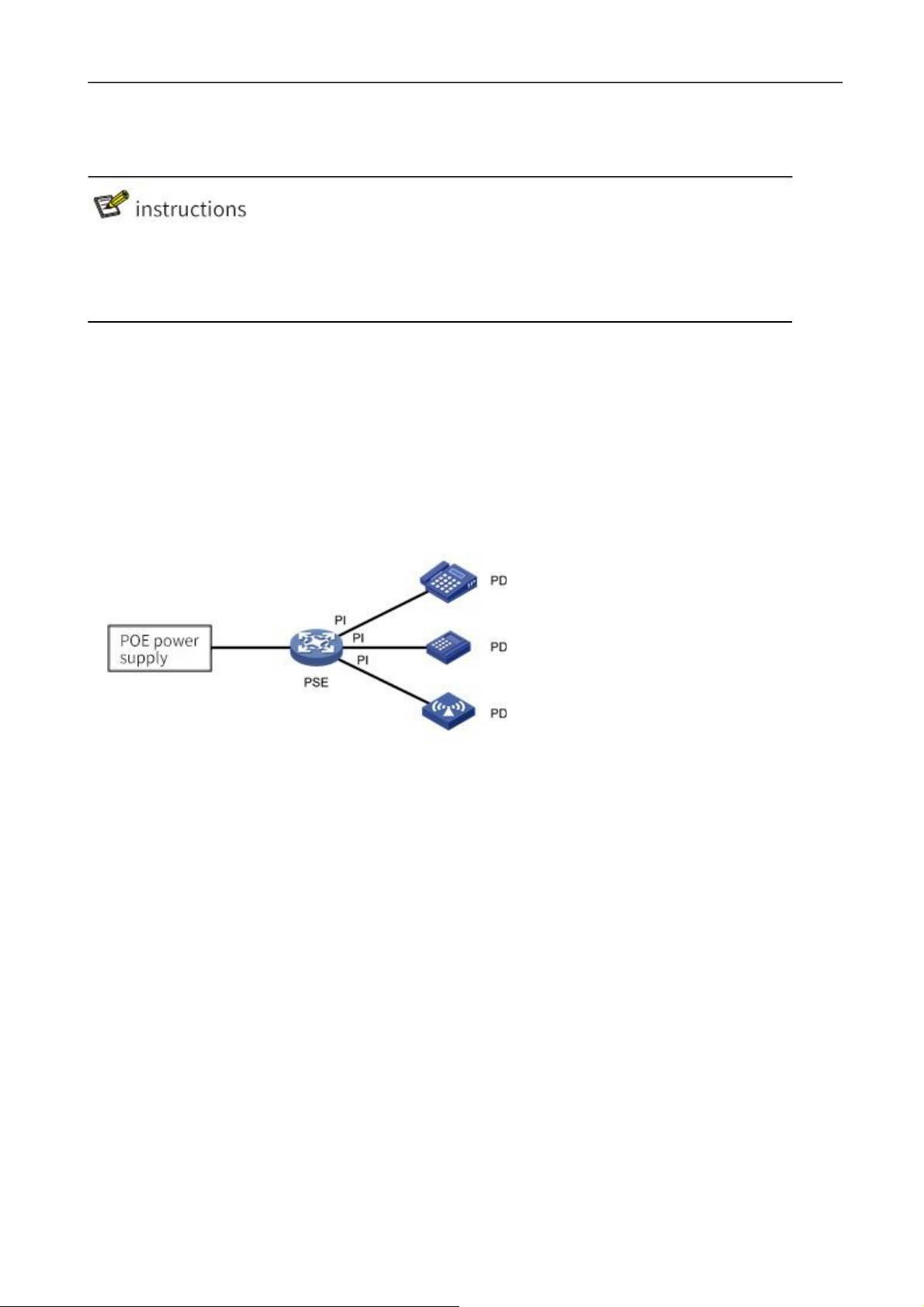
The PoE (Power over Ethernet) refers to the remote Power supply of the equipment via the Ethernet port
by connecting the twisted pair of wires to the external PD (Powered Device).
PoE system composition
The PoE system is shown in figure 2-27, including PoE Power supply, PSE (Power Sourcing Equipment),
PI (Power Interface) and PD.
Figure 2-27 PoE system
1.
The PoE power supply
PoE power supplies the entire PoE system.
2.
The PSE
PSE is the device that directly powers the PD. PSE comes in two flavors: Endpoint (Endpoint) and Midspan
(Endpoint): PSE integrates with the switch, and PSE and the switch are independent. PSE of our company
adopts built-in methods. PSE supports main functions including finding and detecting PD, classifying PD,
supplying power to it, power management, and detecting whether the connection with PD is disconnected,
etc.
3.
The PI,
PI refers to Ethernet interfaces with PoE power supply capability, also known as PoE interfaces, including
FE and GE interfaces.
PoE interface remote power supply has two modes:
Signal line power supply mode: PSE USES 3/5 type twisted pair (1, 2, 3, 6) to transmit data to PD and
direct current at the same time. Idle line power supply mode: PSE USES 3/5 type twisted pair of wires (4,
5, 7, 8) that are not used for data transmission to transmit direct current to PD.
Page 30

P32S36GM Configuration Guide
34
Configuration Items
Explanation
4.
PD
PD is the device that receives PSE power, such as IP phone, wireless AP (Access Point), portable device
charger, card reader, network camera and so on.
PD equipment can be connected to other power sources while receiving PoE power supply for power
redundancy backup.
2.8.2 Configuration PoE
Before configuring PoE functions, make sure that the PoE power supply or PSE is in a normal operating state, otherwise
you may not be able to configure or configure the PoE
The function does not work.
PoE configuration steps:
(1)
Select [interface] -> [PoE management] in the menu to enter the PoE management interface.
(2)
Set the maximum power in PoE global configuration, and click "apply" to complete the
configuration, as shown in figure 2-28.
Figure 2-28 PoE global configuration
PoE global configuration parameters are described in table 2-10.
Table 2-10 PoE global configuration parameter descriptions
Page 31

P32S36GM Configuration Guide
35
The most powerful
By default, the default power provided by the device is 15.4w * port number. For example,
the maximum power provided by 8-port device is 123.2w.
If the maximum power of PoE power supply is less than the maximum output powerof the
equipment, the maximum output power of PoE power supply should be set to-10w (mainboard
power consumption) in order to prevent the power of the equipment from exceeding the PoE
power rating and causing overcurrent of PoE power supply.
Consumed
power
Shows the total power consumed by the PoE.
Power supply
management
The default is energy saving mode, and the power allocated for each port is calculated by
the actual consumed power. PSE will allocate the excess power to other ports by default.
Port mode
The default is DC disconnect mode.
Number of power
supply ports
Displays the number of ports currently powered.
Compatibility mode
ON/OFF, default to OFF.
OFF: only standard PD devices are supported. The detected resistance is between 19k
and 26.5k, and the detected capacitance is less than 150nF.
ON: supports non-standard PD devices, which can supply power to some PD devices
whose detected resistance and capacitance values exceed the standard values.
This function belongs to the global mode and is effective for all ports. It is necessary to
confirm that the device with port access is PD product, otherwise it is easy to cause wrong
power supply to the access device and cause damage to the device.
(3)
Select the port to be configured, click [edit] to enter the interface configuration interface, and
select "enable/disable" the PoE function of this port, as shown in figure 2-29.
Figure 2-29 PoE interface configuration
(4)
Click the "apply" button to complete the operation and return to the PoE main interface, as shown
in figure 2-30.
Page 32

P32S36GM Configuration Guide
36
Configuration Items
Instructions
Enable/disable
Set enable or disable PoE power on ports
State
PoE current power supply state, OFF power supply shutdown state, ON power supply state.
Why
-sheldon: the port is Short of power.
Current
Current operating current of the device.
Power
The power consumed by the current device.
Figure 2-30 PoE interface configuration main interface
(5)
Click the "save" button in the menu to save the configuration. The
PoE port status parameters are described in table 2-11.
Table 2-11 PoE parameter description
• The default power supply priority of the system is: the priority decreases with the increase of port number
• When the external power supply of the equipment is insufficient, the PoE interface with high power supply priority shall
be given priority to power supply.
• If PSE power is low, no matter the priority of newly connected PD, it will not close the port that has been supplied, and no
power will be supplied to newly connected PD.
3 Exchange
3.1 A VLAN
3.1.1 Overview
VLAN is short for Virtual Local Area Network, which is a logical Network divided on a physical Network.
This network corresponds to the second layer of the ISO model. Vlans are not partitioned by the physical
location of the network ports. A VLAN has the same properties as a normal physical network, except that
there are no physical location restrictions. The second layer of unicast, broadcast, and multicast frames
are forwarded and diffused within one VLAN without directly entering into other vlans.
Port-based VLAN is the simplest VLAN partition method. Users can divide the ports on the device into
different vlans, and then the messages received from a certain port can only be transmitted in the
corresponding VLAN, so as to realize the isolation of broadcast domain and the division of virtual working
group.
3.1.2 Link Type
Page 33

P32S36GM Configuration Guide
37
Link connection types of ports can be divided into two types according to different processing methods of
VLAN Tag by ports when forwarding messages:
Access:
Messages sent by the port do not carry VLAN Tag, which is generally used to connect with terminal
devices that cannot recognize VLAN Tag, or when different VLAN members do not need to be
distinguished.
Trunk:
For messages sent by the port, messages in the default VLAN do not carry Tag, while messages in other
vlans must carry Tag. Usually used for interconnection between network transmission devices.
Hybrid:
Messages sent by the port can be set with Tag in some vlans and without Tag in some vlans as required.
Hybrid type ports are used for both interconnection between network transport devices and direct
connection to terminal devices.
3.1.3 Default VLAN (PVID)
In addition to the vlans that ports allow to pass, you can set the default VLAN for ports. By default,
the default VLAN for all ports is VLAN 1, but the user can configure it as needed.
•
The default VLAN for an Access port is the VLAN to which it belongs.
•
Trunk ports and Hybrid ports allow multiple vlans to pass through and configure the default VLAN.
•
When removing a VLAN, if the VLAN is the default VLAN of a port, the default VLAN of the port will
revert to VLAN 1 for Access port; For Trunk or Hybrid ports, the default VLAN configuration for ports does
not change, meaning they can use a VLAN that no longer exists as the default VLAN.
Page 34

P32S36GM Configuration Guide
38
Port Type
Processing of received messages
Processing of sending messages
When a packet is received
without Tag
When a message is
received with Tag
The
Access
Adds the default
VLAN to the message
The Tag
•
Receive this
message when the
VLAN is identical to
the default VLAN
•
When the VLAN is
different from the
default VLAN, the
newspaper is
discarded
Remove Tag and send the text
Trunk
•
VLAN columns
allowed when the
default VLAN is on
the port When the
table is in, it
receives the
message and adds
the Tag of the
default VLAN to the
message
•
When the default
VLAN is not in the
list of vlans that the
port allows to pass,
the message is
discarded
•
The VLAN receives
the message when it is
in the list of vlans that
the port allows to
pass through
•
When the VLAN is
not in the list of vlans
that the port allows to
pass, the message is
discarded
•
When the VLAN is the same as the
default VLAN and in the list of vlans that
ports allow to pass through, remove the
Tag and send the text
•
When the VLAN is different from the
default VLAN and the port is allowed to
pass through the VLAN list, keep the
original Tag and send the text
Hybrid
When the VLAN is in the list of vlans that
the port allows to pass, the user can
manually configure whether to remove the
Tag or not by sending the message
• It is recommended that the default VLAN for this end device port be the same as the default VLAN for the connected
end device port.
• It is recommended to ensure that the default VLAN for the port is the VLAN that the port is allowed to pass through. If a
port does not allow a VLAN to pass through, but the default VLAN of the port is that VLAN, the port discards the received
message of the VLAN or the message without VLAN Tag.
3.1.3.1
Port Processing of Messages
After configuring the port connection type and the default VLAN, there are several different conditions for
the port to receive and send messages, as shown in table 3-1.
Table 3-1 port mail message processing
3.1.4 Configuration VLAN
3.1.4.1
Configure the Access port-based VLAN
Table 3-2 VLAN configuration steps based on Access ports
Introduction to VLAN Configuration
Page 35

P32S36GM Configuration Guide
39
Steps
Configuration Tasks
Instructions
1
Configure the
connection type of the
port
optional
The connection type for the configured port is Access, and by
default, the connection type for the port is Access
2
Create a VLAN
Optionally create one or more vlans
3
Configure the default
VLAN for the port
Configure the default VLAN for Access ports
Steps
Configuration Tasks
Instructions
1
Configure the connection
type of the port
Will choose
The connection type
for the configured port
is Trunk
By default, the port's
connection type is
Access
By default, the Trunk port is
Tagged VLAN (the default VLAN) is VLAN 1
When a Trunk port's Untagged VLAN is changed, the Trunk
port's Untagged VLAN will be automatically Tagged
2
Create a VLAN that needs
to be added to
this Trunk
Optionally create one or more vlans
3
Configure the Trunk to
which the VLAN belongs
Select the Trunk and
add the VLAN
Will choose
Trunk port has only one Untagged VLAN, which is its default
VLAN.
Steps
Configuration Tasks
Instructions
1
Configure the connection
type of the port
Will choose
Configure the
port's
connection type as
Hybrid
By default, the port's
connection type is
Access
Hybrid ports can have multiple Untagged vlans. So,
configure the Hybrid port multiple times through these
two steps
Tagged VLAN will also be available
By default, the Hybrid port's Untagged VLAN is
VLAN 1
2
Create a VLAN that
needs to be added to the
Hybrid port
Optionally create one or more vlans
3
Configure the Trunk to
which the VLAN belongs
Select the Trunk and
add the VLAN
The Hybrid port can have multiple Tagged vlans.
Therefore, Tagged VLAN configured multiple times for
Hybrid ports through these two steps will be valid at the
same
time
Configure a VLAN based on Trunk ports
Table 3-3 VLAN configuration steps based on Trunk ports
Configure vlans based on Hybrid ports
Table 3-4 VLAN configuration steps based on Hybrid ports
3.1.4.2
Configure Ports in the VLAN
Page 36

P32S36GM Configuration Guide
40
Configuration Items
Instructions
ID
Select the group number of the port mirroring group to configure, and you can create a total of
seven mirroring groups.
The name of the
VLAN name, not configurable, default VLAN 1 is default, VLAN 2 is VLAN0002.
Tagged member port
A port member sends a VLAN message with a Tag.
Tagged member port
A port member sends a VLAN message without a Tag.
The editor
Select the VLAN ID to edit and click this button to enter the edit interface.
Add
Click this button to enter the VLAN add interface.
Delete
Select the VLAN ID to edit, and click this button to remove the VLAN.
The VLAN configuration interface is shown in figure 3-1, and the detailed description of each parameter is
shown in table 3-5.
Figure 3-1 VLAN configuration interface
Table 3-5 VLAN configuration parameters
Configuration steps:
(1)
Select [switch] -> [VLAN] in the menu to enter the VLAN configuration interface, as shown in figure
3-2.
Figure 3-2 VLAN display interface
Figure 3-3 VLAN configuration interface
(2)
Click the "add" button to enter the page as shown in picture 3-3.
(3)
Configure the port members of VLAN, click the "apply" button to complete the operation.
(4)
Click the "save" button in the menu to save the configuration.
3.1.4.3
Configure the VLAN to Which the Port Belongs
The interface configuration interface is shown in figure 3-4, and the detailed description of each
parameter is shown in table 3-6.
Page 37

P32S36GM Configuration Guide
41
Configuration Items
Instructions
Name
Corresponding port name.
VLAN mode
The Access
Configure the port type to be an Access port.
Trunk
Configure the port type to be Trunk.
Hybrid
Configure the port type to be the Hybrid port.
PVID
PORT-BASE VLAN ID, suitable for Access PORT.
Native Vlan
Native vlans (Native vlans) are Native to the Trunk.
The editor
Select the port to edit and click this button to enter the edit interface.
Figure 3-4 interface display interface
Table 3-6 interface configuration parameters
Configuration steps:
(1)
Select [switch] -> [VLAN] in the menu to enter the interface configuration interface, as shown in
figure 3-4.
(2)
Select the port to be configured and click the "edit" button to enter the interface configuration page.
(3)
Configure the VLAN mode of the port, PVID or Native VLAN. In general, it is recommended
to configure the Native VLAN in the Trunk as 1. The configuration interface is shown in figure 3-
6.
Figure 3-6 VLAN configuration interface
(4)
Click the "save" button in the menu to save the configuration.
3.1.5 VLAN Configuration Example
Configuration example:
Page 38

P32S36GM Configuration Guide
42
Case requirements: Switch A and Switch B connect with each other through trunk. PCS of the same
VLAN can exchange visits, and PCS of different VLANs are forbidden to exchange visits. The network
topology is shown in FIG. 3-7.
Figure 3-7 network topology diagram
Switch A configuration:
Step 1: configure eth0/9 as a Trunk and Native VLAN as a default of 1.
Select [VLAN] in the menu [switch] to enter the interface configuration interface. Select port eth0/9 and
click the "edit" button to enter configuration mode, as shown in figure 3-8.Select Trunk for VLAN mode,
Native VLAN default is 1.
Figure 3-8 interface configuration interface
Step 2: create VLAN 10, VLAN 20, and add VLAN 10 and VLAN 20 to Trunk eth0/9.
Under the Tagged member port, click "add" button to enter the VLAN editing interface, as shown in figure
3-9. Enter "10,20" in the dialog box, select port eth0/9 from Tagged member port, and click "apply" button
to complete the configuration.
Figure 3-9 VLAN configuration interface
Step 3: configure port eth0/1 VLAN mode for Access and PVID 10.
Page 39

Switch Web Configuration Guide
43
Under the “Interface” section, select eth0/1 and click the "edit" button to enter the interface configuration
interface, as shown in figure 3-10. VLAN mode is the default Access and PVID is configured at 10.Click
the "apply" button to complete the configuration.
Figure 3-10 VLAN configuration interface
Step 4: configure port eth0/2 VLAN mode for Access and PVID 20.
In step 3, set eth0/2's VLAN mode to Access and PVID to 20.Click [apply] to complete the configuration,
and the VLAN interface is shown in figure 3-11:
Figure 3-11 VLAN interface
Step 5: click the "save" button in the menu to save the configuration.
Switch B configuration:
Eth0/9 and eth0/10 are configured with the Switch A. Create VLAN 10 and VLAN 20 and complete the
corresponding port configuration. After configuration, the VLAN interface is shown in figure 3-12.
Figure 3-12 VLAN interface
Page 40

Switch Web Configuration Guide
44
3.2 ERPS
3.2.1 ERPS Function Overview
ERPS (Ethernet Ring Protection Switching protocol) is a network Protection protocol developed for the ITU,
also known as g.8032.It is a link layer protocol for Ethernet ring networks. It can prevent broadcast storms
caused by the data loop when the Ethernet is complete and quickly restore communication between the nodes
of the Ethernet when one link is disconnected.
At present, STP is another technology to solve the problem of two-layer network loop. STP is more mature, but
its convergence time is longer (second level). ERPS is a link-layer protocol specially used in Ethernet ring
networks. The two-layer convergence performance is up to 50ms, which has a faster convergence rate than
STP.
Figure 3-13 typical ERPS networking
3.2.2 Introduction to ERPS Principle
ERPS is a standard ring network protocol dedicated to Ethernet link layer. Only two ports can join the same
ERPS ring on each layer switching device. In an ERPS ring, to prevent a loop from appearing, you can start a loop
breaking mechanism that blocks the RPL owner port and eliminates the loop. When link failure occurs in the ring
network, the equipment running ERPS protocol can quickly release blocking ports, perform link protection
switching, and restore link communication between nodes in the ring network. This section mainly
introduces the basic implementation principle of ERPS under single-ring networking in the form of example
according to the process of link normal-> link fault-> link recovery (including protection switching operation).
3.2.2.1
As shown in figure 3-14, all devices on the Switch A ~ Switch E circuit communicate normally.
FIG. 3-14 normal ERPS link
Normal Links
Page 41

Switch Web Configuration Guide
45
To prevent loop generation, ERPS first blocks the RPL owner port, which is also blocked if the RPL neighbor
port is configured, so that other ports can normally forward traffic.
3.2.2.2 Link Fault
As shown in figure 3-15, when the link between Switch D and Switch E fails, the ERPS protocol starts the
protection switching mechanism, blocks the ports at both ends of the fault link, and then releases the RPL
owner port. The two ports resume the receiving and sending of user traffic, thus ensuring the uninterrupted
traffic.
Figure 3-15 ERPS link failure
Page 42

Switch Web Configuration Guide
46
3.2.2.3 Link Recovery
When the link returns to normal, ERPS rings are configured with a backcut mode by default, and the device
that owns the RPL owner port re-blocks traffic on the RPL link, and the original fault link is reused to complete
the transfer of user traffic.
3.2.2.4 ERPS Ring Types
Single Ring:
For example, in figure 3-16, there is only one ring in the network topology; only one RPL Owner; only one RPL
link; All nodes need to have the same RAPS managed VLAN
= All devices in the ring need to support ERPS.
= Links between devices in the ring network must be directly connected, without intermediate equipment.
Figure 3-16 ERPS single-loop model
Tangent Ring:
An application scenario in which two or more rings sharing a single device in a network topology needs
protection. For example, in figure 3-17, two rings in the network topology share one device. Each ring has
one and only one blocking point, and each ring has one and only one RPL link. Different rings need to
have different RAPS management VLANs.
= All devices in the ring need to support ERPS.
= Links between devices in the ring network must be directly connected, without intermediate
equipment.
FIG. 3-17 ERPS tangential ring model
Page 43

Switch Web Configuration Guide
47
Intersecting Rings:
In a network topology, two or more rings share a link (the two intersecting nodes must be directly connected,
and no other nodes are allowed).Take figure 3-18 as an example, there are two rings in the network
topology. Each ring has one RPL owner node and each ring has one RPL link. Different rings need to have
different RAPS management VLANs.
= All devices in the ring need to support ERPS。
= Links between devices in the ring network must be directly connected, without intermediate
equipment。
Figure 3-18 ERPS intersecting ring model
3.2.3 ERPS configuration profile
•
The spanning tree protocol and the ERPS protocol cannot be turned on at the same time.
3.2.3.1 ERPS Management Interface
Click [exchange] -> [ERPS] in the menu to enter the ERPS overview interface, as shown in figure 3-19, and
the specific description of parameter information is shown in table 3-8.
Figure 3-19 ERPS overview interface
Page 44

Switch Web Configuration Guide
48
Configuration Item
instructions
Naming
The name of the ERPS ring
Ring Number
Number of ERPS rings
State
The current state of the ERPS ring, including:
Idle: idle state, no fault, cutback already
Pending: no fault Pending backcut
Protection: failure condition Protection
Previous Event
Recent state machine events, including:
RAPS-NR: remote fault recovery event
RAPS-NR-RB: remote backcut event
RAPS-SF: remote fault event
LOCAL-SF: LOCAL fault event
LOCAL-CLEAR-SF: local fault recovery event
WTR-EXP: local callback event
East interface
Eastward interface of ERPS ring
West Interface
Westward interface of ERPS ring
Cut Back
When the fault link resumes, you can choose to manually cut back immediately,
otherwise the system will automatically cut back after 5 minutes
Table 3-7 description of ring configuration parameters
Page 45

Switch Web Configuration Guide
49
Configuration
Items
instructions
Ring number
ERPS ring ID, which can be any number. Each ERPS ring must have a unique ring
number.
East interface
Specifies that a port on the switch is an
eastbound port
East port and west port are relatively
defined, without strict distinction, that
is, the loop can enter and exit at this
point.
West interface
Specifies that a port on the switch is a
westbound port
3.2.3.2 ERPS Ring Configuration
In the ERPS interface, click the "configure" button in the upper left corner to enter the ERPS ring
configuration interface. Click the "add" button to add ERPS ring. After the configuration is completed, click
the "apply" button, as shown in FIG. 3-20.
Figure 3-20 ERPS ring configuration
Table 3-8 configuration parameters
After the configuration is completed, return to the ERPS ring configuration interface. Click the "delete"
button after the ring entry to delete the ERPS ring, as shown in figure 3-21.
Figure 3-21 ERPS ring configuration
Page 46

Switch Web Configuration Guide
50
Configuration
items
instructions
Naming
Instance names, string format, need to be unique, such as number "1", character
"aa"
ID
Configure VLAN Instance for ERPS Instance protection; All VLANs belong to
Instance 0 by default; The default id is 0.
Ring Number
The associated ring ID must be the ring already created
Level
ERPS priority, default is 0
RAPS Management
VLAN
Each switch in the same ring must be configured with the same RAPS management
VLAN for transmitting ERPS protocol messages.
A RAPS management VLAN can be a virtual VLAN, requiring a distinction from a
data VLAN, without the need for actual creation.
Data VLAN
ERPS data VLANs, setting up the VLANs that are allowed to transfer in the ERPS
ring. Must be an existing VLAN if
It does not exist please add in VLAN configuration;
Support VLAN Range class configuration, such as "1-3,5" for VLAN 1,2,3,5;
The Owner
Interface
Main ring ERPS Owner node, can choose east interface or west interface as Owner
node.
Each ERPS ring has only one device configured as an RPL owner node that controls
the end that needs to be blocked
Sub - Ring
Blocking Mouth
Sub - ring blocking mouth, a sub - ring only a blocking mouth, you can choose east
or west.
This parameter needs to be configured only when the ring is tangential, and the subring of the two devices whose rings are tangential must have a
3.2.3.3 ERPS Instance Configuration
Click the "+ add" button of ERPS instance configuration to enter the interface. After the configuration is
completed, click the "apply" button, as shown in figure 3-22. Specific parameters of the instance
configuration are described in table 3-9.
Figure 3-22 ERPS instance configuration
Table 3-9 Ring Configuration Parameters
Page 47

Switch Web Configuration Guide
51
sub-ring blocking port.
Associated
Instance
Only need to configure the sub-ring blocking port, set to the ring ID tangent to the
current sub-ring
3.2.4 Examples of Single Ring Configuration
Case requirements:
A ring network with 3 switches, as shown in Figure 3-21, the default blocking port is configured to be the
eth0/9 port of S1. When a failure occurs, the link can be restored in time to ensure that the network is
available. The data VLAN is 1, 2, 3.
Figure 3-23 ERPS network topology
3.2.4.1 Configure Switch S1
Step 1: configure ports 9 and 10 for trunk ports and Native VLAN for default value 1.
Select [VLAN] from the sub-item of [switch] in the menu to enter the interface configuration interface,
select ports eth0/9 and eth0/10, and click the [edit] button to enter the configuration mode, as shown in
figure 3-24.Select "Trunk" for VLAN mode, Native VLAN defaults to "1".
Figure 3-24 port configuration interface
Click the "apply" button, and the interface returned is shown in figure 3-25.
Figure 3-25 port status display interface
Page 48

Switch Web Configuration Guide
52
Step 2: create VLAN 2, 3, 4 and add VLAN 2, 3, 4 to Trunk ports eth0/9, eth0/10.
In the VLAN interface, as shown in Figure 3-26, click the [Add] button, enter "2-4" in the ID, and check eth0/9
and eth0/10 for the Tagged member port
Figure 3-36 create VLAN 2, 3, and 4
Click the "apply" button, and the interface returned is shown in figure 3-27.
Figure 3-27 port status display interface
Step 3: Create ERPS ring ID, set east-west interface.
Select [ERPS] in the menu [exchange] and enter the ERPS configuration interface. Click the button [+
add] to enter the ERPS ring configuration interface, as shown in figure 3-28.The ring number is set to "1",
the east interface to "eth0/9", and the west interface to "eth0/10".
Figure 3-28 ERPS ring configuration interface
Click the "apply" button to return to the following page, as shown in picture 3-29.
Figure 3-29 ERPS ring configuration display interface
Page 49

Switch Web Configuration Guide
50
Step 4: create an ERPS instance and set the ring name, number, blocking port and other parameters.
In the ERPS configuration interface, select the instance configuration and click [+ add] button to enter the
ERPS instance configuration interface, as shown in figure 3-30.Name "1", ring number "1", level "0", RAPS
management VLAN "1000", Owner interface "East", sub ring blocking port "None".
Figure 3-30 ERPS instance configuration interface
Click the "apply" button to return to the following page:
Figure 3-31 ERPS instance configuration display interface
Step 5: select the "save" button on the navigation bar and save the configuration.
•
In the case of single ring, only one blocking point needs to be set, and the choice of blocking point is generally
considered in the middle of the ring.
3.2.4.2 Configure Switch S2 and S3
Step 1: configure ports 9 and 10 for trunk and Native VLAN for default value 1.
Select [VLAN] in the menu [switch] to enter the interface configuration interface, select ports "eth0/9" and
"eth0/10", click the "edit" button to enter the configuration mode, as shown in the figure. Select "Trunk" for
VLAN mode, Native VLAN defaults to "1".
Step 2: Create VLAN 2, VLAN 3, and add VLAN 2 and VLAN 3 to Trunk ports eth0/9 and eth0/10.
In the VLAN interface, click the [Add] button, enter "2-3" in the ID, and check eth0/9 and eth0/10 for the
tagged member ports.
Page 50

Switch Web Configuration Guide
51
Step 3: create the ERPS ring and set up the thing interface.
Select [ERPS] in the menu [exchange] and enter the ERPS configuration interface. Click the button [+ add] to
enter the ERPS ring configuration interface, as shown in figure 3-27.The ring number is set to "1", the
eastern interface to "eth0/9", and the western interface to "eth0/10".
Step 4: create an ERPS instance.
In the ERPS configuration interface, select the instance configuration and click [+ add] button to enter the
ERPS instance configuration interface, as shown in figure 3-32.Name "1", ring number "1", level "0", RAPS
management VLAN "1000", Owner interface "None", sub ring blocking port "None". Figure 3-32 ERPS
instance configuration display interface
Unlike S1, S2 and S3 are in the break point Owner interface =None.
Step 5: select the "save" button on the navigation bar and save the configuration.
3.2.5 Examples of Tangential Ring Configuration
The topology diagram is shown in Figure 3-33. S1 is located in the central computer room and can be
supervised and maintained by the administrator in real time. It has high reliability; S2-S5 is distributed in
various deployment points. In order to improve the reliability of the network, avoid single The single-point
failure risk of the link external connection, while avoiding the single-machine failure risk that may occur
when the dual-link external single-machine is connected, the dual-link external connection forms a ring
network. The data VLANs are 1, 2, 3, and 4, and each ring network is required to converge quickly when
a single point of failure occurs to avoid user network interruption.
Figure 3-33 network topology
3.2.5.1 Divide Main Ring and Sub-Ring
Page 51

Switch Web Configuration Guide
52
parameter
equipmen
t
Ring
numbe
r
RAPS VLAN
The
Own
er interface
Sub - ring
blocking
mouth
Associated instance
Switch S2
1
1000
Eth0/9
None
\
Switches S3
1
1000
None
None
\
Switch S1
1
1000
None
None
\ 2 1001
None
None
\
Switches S4
2
1001
Eth0/9
None
\
Switch the S5
2
1001
None
None
\
•
The ring ID of the primary and subring must be different.
•
The RAPS management VLANs within the primary and subring must be different.
There is no strict distinction between the main ring and the sub-ring. Generally once one of the main rings
is assumed, and the other is a sub-ring. In this example, the ring composed of S1, S2 and S3 is defined as
the main ring, the ring number is "1", the blocking port is "eth0/9" of S2, the RAPS management VLAN is
"1000", the ring composed of S1, S4 and S5 is a sub-ring, the ring number is "2", the blocking port is
"eth0/9" of S4, and the RAPS management VLAN is "1001", the specific parameters are shown in table 3-
10.
Table 3-10 equipment parameters chart
3.2.5.2 Configure Switch S1
Step 1: configure ports 9, 10, 11, 12 as trunk ports and Native VLAN as default value 1.
Select [VLAN] from the sub-item of [switch] in the menu to enter the VLAN configuration interface. In the
interface configuration item, select ports eth0/9, eth0/10, eth0/11, eth0/12, and click the edit button to enter
the configuration mode, as shown in figure 3-34.Select "Trunk" for VLAN mode, Native VLAN defaults to
"1".
Figure 3-34 port configuration interface
Click the "apply" button, and the return to the Interface as shown in figure 3-35.
Figure 3-35 port status display interface
Page 52

Switch Web Configuration Guide
53
Step 2: create VLAN 2, 3, 4 and add VLAN 2, 3, 4 to Trunk ports eth0/9, eth0/10, eth0/11, and eth0/12.
Tagged member ports are Tagged with eth0/9, eth0/10, eth0/11, and eth0/12.
Figure 3-36 create VLAN 2, 3, and 4
Click the "apply" button, and the interface returned is shown in figure 3-37.
Figure 3-37 port status display interface
Step 3: create the ERPS main ring and subring and set up the east-west interface.
(1)
Create the main ring
Select [ERPS] in the menu [exchange] and enter the ERPS configuration interface. Click the button [+
add] to enter the ERPS ring configuration interface, as shown in figure 3-38.The ring number is set to "1",
the eastern interface to "eth0/9", and the western interface to "eth0/10".
Figure 3-38 creates the ERPS main ring
(2)
Create subrings
Page 53

Switch Web Configuration Guide
54
Select [ERPS] in the menu [exchange] and enter the ERPS configuration interface. Click the button [+
add] to enter the ERPS ring configuration interface, as shown in figure 3-39.The ring number is set to "2",
the eastern interface to "eth0/11", and the western interface to "eth0/12".
Figure 3-39 creates an ERPS subring
Click the "apply" button to return to the following page:
Figure 3-40 ERPS ring configuration display interface
Step 4: create an ERPS instance
(1)
Create ERPS instance 1
In the ERPS interface, select the instance configuration and click [+ add] button to enter the ERPS
instance configuration interface, as shown in figure 3-41.Name "1", ring number "1", level "0", RAPS
management VLAN "1000", Owner interface "None", sub ring blocking port "None".
Figure 3-41 ERPS instance configuration interface
(2)
Create ERPS instance 2
In the ERPS configuration interface, select the instance configuration and click [+ add] button to enter the
ERPS instance configuration interface, as shown in figure 3-42.Name "2", ring number "2", level "0", RAPS
management VLAN "1001", Owner interface "None", sub ring blocking port "None".
Figure 3-42 ERPS instance configuration interface
Page 54

Switch Web Configuration Guide
55
Click the "apply" button to return to the following page, as shown in picture 3-43:
Figure 3-43 ERPS instance configuration display interface
Step 5: select the "save" button on the navigation bar and save the configuration.
3.2.5.3 Configure switch S2
Step 1: configure ports 9 and 10 as trunk ports and Native VLAN as default value 1.
Select [VLAN] in the [Switch] sub-item of the navigation bar to enter the VLAN configuration interface. In the
interface configuration item, select ports eth0/9, eth0/10, and click the [Edit] button to enter the configuration
mode, as shown in the figure. Select "Trunk" for VLAN mode, and Native VLAN defaults to "1". Click the
[Apply] button, and you’ll return to the “Interface” section as shown in Figure 3-44.
Figure 3-44 port status display interface
Step 2: create VLAN 2, VLAN 3, and VLAN 4, and add VLAN 2, 3, and 4 to Trunk eth0/9 and eth0/10.
Under the VLAN option, click the "add" button, enter "2-4" in the ID, Tagged member port, and tick eth0/9
and eth0/10.Click the "apply" button, and the interface returned is shown in figure 3-45.
Figure 3-45 port status display interface
Page 55

Switch Web Configuration Guide
56
Step 3: Create the ERPS ring and set up the thing interface.
Select "ERPS" from the "switch" sub-item in the menu and enter the ERPS configuration interface. Click "+
add" button to enter the ERPS ring configuration interface. The ring number is set to "1", the eastern
interface to "eth0/9", and the western interface to "eth0/10".Click the "apply" button, and the return page is
shown in figure 3-46:
Figure 3-46 ERPS ring configuration display interface
Step 4: Create an ERPS instance and set up the blocking port.
In the ERPS configuration interface, select the instance configuration and click the "+ add" button to enter
the ERPS instance configuration interface. The name is "1", ring number "1", level "0", RAPS management
VLAN "1000", Owner interface "East", and sub ring blocking port is "None". Click the "apply" button to return
to the page as shown in figure 3-47:
Figure 3-47 ERPS instance configuration display interface
Step 5: select the "save" button on the navigation bar and save the configuration.
3.2.5.4 Configure Switch S3
Step 1: configure ports 9 and 10 as trunk ports and Native VLAN as default value 1.
Select [VLAN] from the sub-item of [switch] in the menu to enter the port configuration interface,
select ports eth0/9 and eth0/10, and click the button of [edit] to enter the configuration mode. Select
"Trunk" for VLAN mode, Native VLAN defaults to "1".Click the "apply" button, and the interface
returned is shown in figure 3-48.
Figure 3-48 port status display interface
Page 56

Switch Web Configuration Guide
57
Step 2: create VLAN 2, VLAN 3, and VLAN 4, and add VLAN 2, 3, and 4 to Trunk eth0/9 and eth0/10.
Under the VLAN interface, click the "add" button, enter "2-4" in the ID, Tagged member port and tick eth0/9
and eth0/10.Click the "apply" button, and return to the “Interface” section as shown in figure 3-49.
Figure 3-49 port status display interface
Step 3: create the ERPS ring and set up the east-west interface.
Select "ERPS" from the "switch" sub-item in the menu and enter the ERPS configuration interface. Click
"+ add" button to enter the ERPS ring configuration interface. The ring number is set to "1", the eastern
interface to "eth0/9", and the western interface to "eth0/10".Click the "apply" button to return to the page
as shown in figure 3-50:
Figure 3-50 ERPS ring configuration display interface
Step 4: create an ERPS instance and set up the blocking port.
In the ERPS configuration interface, select the instance configuration and click [+ add] button to enter the
ERPS instance configuration interface. Set the name "1", ring number "1", level "0", RAPS management
VLAN "1000", Owner interface "None", sub ring blocking port "None". Click the "apply" button to return to
the page as shown in figure 3-51:
Figure 3-51 ERPS instance configuration display interface
Step 5: select the "save" button on the navigation bar and save the configuration.
Page 57

Switch Web Configuration Guide
58
3.2.5.5 Configure Switch S4
Step 1: configure ports 9 and 10 as trunk ports and Native VLAN as default value 1.
Select [VLAN] from the sub-item of [switch] in the menu to enter the interface configuration interface,
select ports eth0/9 and eth0/10, and click the button of [edit] to enter the configuration mode. Select
"Trunk" for VLAN mode, Native VLAN defaults to "1".Click the "apply" button, and the interface
returned is shown in figure 3-52.
Figure 3-52 port status display interface
Step 2: create VLAN 2, VLAN 3, and VLAN 4, and add VLAN 2, 3, and 4 to Trunk eth0/9 and eth0/10. Under
the VLAN interface, click the "add" button, enter "2-4" in the ID, Tagged member port and tick eth0/9 and
eth0/10.Click the "apply" button, and return to the “Interface” section as shown in figure 3-53.
Figure 3-53 port status display interface
Step 3: create the ERPS ring and set up the east-west interface.
Select [ERPS] in the menu [exchange] and enter the ERPS configuration interface. Click the button [+
add] to enter the ERPS ring configuration interface, as shown in figure 3-54.The ring number is set to "2",
the eastern interface to "eth0/9" and the western interface to "eth0/10".Click the "apply" button to return
to the following page:
Figure 3-54 ERPS ring configuration display interface
Step 4: create an ERPS instance and set up the blocking port.
Page 58

Switch Web Configuration Guide
59
In the ERPS configuration interface, select the instance configuration and click [+ add] button to enter the
ERPS instance configuration interface, as shown in figure 3-55.Name "2", ring number "2", level "0", RAPS
management VLAN "1001", Owner interface "East", sub ring blocking port "None".
Click the "apply" button to return to the following page:
Figure 3-55 ERPS instance configuration display interface
Step 5: select the "save" button on the navigation bar and save the configuration.
3.2.5.6 Configure Switch S5
Step 1: configure ports 9 and 10 as trunk ports and Native VLAN as default value 1.
Select [VLAN] in the menu [switch] to enter the interface configuration interface, select ports eth0/9 and
eth0/10, click the button [edit] to enter the configuration mode, as shown in the figure. Select "Trunk" for
VLAN mode, Native VLAN defaults to "1".Click the "apply" button, and the interface returned is shown in
figure 3-56.
Figure 3-56 port status display interface
Step 2: create VLAN 2, VLAN 3, and VLAN 4, and add VLAN 2, 3, and 4 to Trunk eth0/9 and eth0/10.
Under the VLAN interface, click the "add" button, enter "2-4" in the ID, Tagged member port and tick eth0/9
and eth0/10.Click the "apply" button, and the interface returned is shown in figure 3-57.
Figure 3-57 port status display interface
Step 3: create the ERPS ring and set up the east-west interface.
Select [ERPS] in the menu [exchange] and enter the ERPS configuration interface. Click the button [+
add] to enter the ERPS ring configuration interface, as shown in figure 3-58.The ring number is
Page 59

Switch Web Configuration Guide
60
set to "2", the eastern interface to "eth0/9" and the western interface to "eth0/10".Click the "apply" button
to return to the following page:
Figure 3-58 ERPS ring configuration display interface
Step 4: create an ERPS instance and set up the blocking port.
In the ERPS configuration interface, select the instance configuration and click [+ add] button to enter the
ERPS instance configuration interface, as shown in figure 3-57.Name "2", ring number "2", level "0", RAPS
management VLAN "1001", Owner interface "None", sub ring blocking port "None".
Click the "apply" button to return to the following page, as shown in picture 3-59:
Figure 3-59 ERPS instance configuration display interface
Step 5: select the "save" button on the navigation bar and save the configuration.
3.2.6 Intersecting Ring Configuration Example
As shown in Figure 3-60, S1, S2, S3, and S4 form an intersecting ring, and the data VLAN is 1, 2, 3, and
4. It is required that rapid convergence can be achieved when a single point of failure occurs in each ring;
the network can at most have two failure points (different rings) without user disconnection, achieving
optimal reliability.
Figure 3-60 ERPS intersecting ring
3.2.6.1 Divide Main Ring and Sub-Ring
Page 60

Switch Web Configuration Guide
60
parameter
equipmen
t
Ring
numbe
r
RAPS VLAN
The
Own
er interface
Sub - ring
blocking
mouth
Associated instance
Switch S1
1
1000
None
None
\ 2 1001
None
Eth0/9
1
Switch S2
1
1000
None
None
\ 2 1001
None
Eth0/10
1
Switches S3
1
1000
Eth0/9
None
\
Switches S4
2
1001
Eth0/9
None
\
•
The ring ID of the primary and subring must be different.
•
The RAPS management VLAN within the primary and subring must be different
•
In the sub-ring, the port corresponding to the link where the main ring intersects with the sub-ring must be set as the blocking
port, and the associated instance is set as the main ring.
There is no strict distinction between the main ring and the sub-ring. Generally one of the main rings is
assumed, and the other is a sub-ring. In this example, the ring composed of S1, S2 and S3 is defined as
the main ring, the ring number is "1", the blocking point is S3 eth0/9 port, and the RAPS management
VLAN is "1000".The ring composed of S1, S2 and S4 is a sub-ring, the ring number is "2", the breaking
point is eth0/9 port of S4, the RAPS management VLAN is "1001", and the intersecting link of the two rings
is eth0/9 of S1 to eth0/10 of S2.Specific parameters are described in table 3-11.
Table 3-11 equipment parameters list
3.2.6.2 Configure Switch S1
Step 1: Configure ports 9, 10 and 11 as trunk ports and Native VLAN as default value 1.
Select [VLAN] from the sub-item of [switch] in the menu to enter the VLAN configuration interface. Under the
interface configuration option, check ports eth0/9, eth0/10 and eth0/11, and click the edit button to enter the
configuration mode, as shown in figure 3-61.Select "Trunk" for VLAN mode, Native VLAN defaults to "1".
Figure 3-61 port configuration interface
Click the "apply" button, and return to the “Interface” section as shown in figure 3-62.
Figure 3-62 port status display interface
Page 61

Switch Web Configuration Guide
61
Step 2: Create VLAN 2, VLAN 3, and VLAN 4, and add VLAN 2, 3, and 4 to Trunk ports eth0/9, eth0/10, and
eth0/11.
In the VLAN interface, click the [Add] button, enter "2-4" in the ID, and select eth0/9, eth0/10, and eth0/11 for
the tagged member ports.
Figure 3-63 create VLAN 2, 3, and 4
Click the "apply" button, and the interface returned is shown in figure 3-64.
Figure 3-64 VLAN state display interface
Step 3: Create the ERPS main ring and subring and set up the thing interface.
(1)
Create the main ring
Select [ERPS] in the menu [exchange] and enter the ERPS configuration interface. Click the button [+
add] to enter the ERPS ring configuration interface, as shown in figure 3-65.The ring number is set to "1",
the eastern interface to "eth0/9", and the western interface to "eth0/10".
Figure 3-65 ERPS ring configuration interface
(2)
Create subrings
Select "ERPS" from the "switch" sub-item in the menu and enter the ERPS configuration interface. Click "+
add" button to enter the ERPS ring configuration interface, as shown in figure 3-66.The
Page 62

Switch Web Configuration Guide
62
ring number is set to "2", the eastern interface to "eth0/9", and the western interface to "eth0/11".Note that
the eth0/9 (eastern interface) of the subring needs to be configured as a subring interrupter.
Figure 3-66 ERPS ring configuration interface
Click the "apply" button to return to the following page:
Figure 3-67 ERPS ring configuration display interface
Step 4: create an ERPS instance and set up the blocking port.
(1)
create ERPS instance 1
In the ERPS configuration interface, select the instance configuration and click [+ add] button to enter the ERPS
instance configuration interface.
Figure 3-68 ERPS instance configuration interface
As shown in figure 3-68, name "1", ring number "1", level "0", RAPS management VLAN "1000", Owner
interface "None", sub ring blocking port "None".
(2)
Create ERPS instance 2
In the ERPS configuration interface, select the instance configuration and click [+ add] button to enter the
ERPS instance configuration interface, as shown in figure 3-69.Name "2", ring number "2", level "0", RAPS
management VLAN "1001", Owner interface "None", sub ring blocking port "East", associated instance
select "1".
Figure 3-69 ERPS instance configuration interface
Page 63
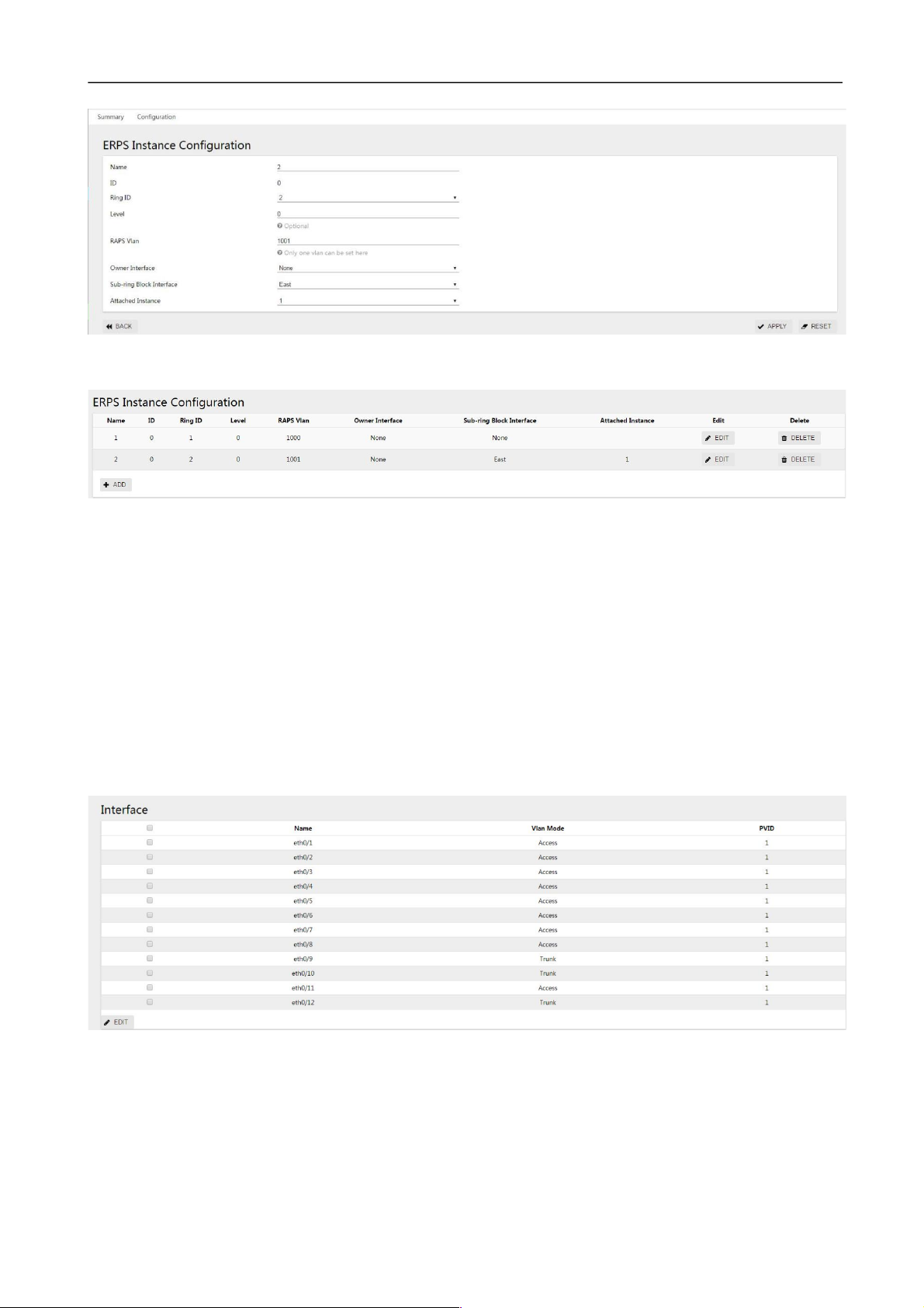
Switch Web Configuration Guide
63
Click the "apply" button to return to the following page:
Figure 3-70 ERPS instance configuration display interface
Step 5: select the "save" button on the navigation bar and save the configuration.
3.2.6.3 Configure Switch S2
Step 1: configure ports 9, 10 and 12 as Trunk ports and Native VLAN as default value 1.
Select [VLAN] from the sub-item of [switch] in the menu to enter the VLAN configuration interface. In the
interface configuration options, select ports eth0/9, eth0/10, eth0/12, and click the edit button to enter the
configuration mode. Select "Trunk" for VLAN mode, Native VLAN defaults to "1".Click the "apply" button,
and return to the “Interface” section as shown in figure 3-71.
Figure 3-71 port status display interface
Step 2: create VLAN 2, VLAN 3, and VLAN 4, and add VLAN 2, 3, and 4 to Trunk eth0/9, eth0/10, and
eth0/12.
Under the VLAN interface, click "add" button, enter "2-4" in ID, Tagged member port, tick eth0/9, eth0/10,
eth0/12, and click "apply" button and return to the “Interface” section as shown in figure 3-72.
Figure 3-72 port status display interface
Page 64

Switch Web Configuration Guide
64
Step 3: create the main ring and sub-rings and set up the east-west interface.
(1)
Create the main ring
Select [ERPS] from the [switch] subitem in the menu to enter the ERPS configuration interface. Click [+
add] button to enter the ERPS ring configuration interface. The ring number is set to "1", the eastern
interface is set to "eth0/9", and the western interface is set to "eth0/10".
(2)
Create subrings
Select [ERPS] in the menu [switch] and enter the ERPS configuration interface. Click [+ add] to enter the
ERPS ring configuration interface. The ring number is set to "2", the eastern interface is set to "eth0/10",
and the western interface is set to "eth0/12".Click the "apply" button to return to the following page:
Figure 3-73 ERPS ring configuration display interface
Step 4: create an ERPS instance and set up the blocking points.
(1)
Create the main ring instance
In the ERPS configuration interface, select the instance configuration and click [+ add] button to enter the
ERPS instance configuration interface. Name "1", ring number "1", level "0", RAPS management VLAN
"1000", Owner interface "None", sub ring blocking port "None".
(2)
Create a sub-ring instance
In the ERPS configuration interface, select the instance configuration and click [+ add] button to enter the
ERPS instance configuration interface. Name "2", ring number "2", level "0", RAPS management VLAN
"1001", Owner interface "None", sub ring blocking port "East", associated instance select "1".Click the
"apply" button to return to the following page, as shown in figure 3-74:
Figure 3-74 ERPS instance configuration display interface
Step 5: select the "save" button on the navigation bar and save the configuration.
Page 65

Switch Web Configuration Guide
65
3.2.6.4 Configure Switch S3
Step 1: configure ports 9 and 10 as trunk ports and Native VLAN as default value 1.
Select [VLAN] from the [switch] sub-menu in the menu to enter the VLAN interface configuration interface.
In the interface configuration options, select ports eth0/9 and eth0/10, and click the [edit] button to enter
the configuration mode. Select "Trunk" for VLAN mode, Native VLAN defaults to "1".Click the "apply" button,
and return to the “Interface” section as shown in figure 3-75.
Figure 3-75 VLAN state display interface
Step 2: create VLAN 2, VLAN 3, and VLAN 4, and add VLAN 2, 3, and 4 to Trunk eth0/9 and eth0/10. Under
the VLAN interface, click the "add" button, enter "2-4" in the ID, Tagged member port and tick eth0/9 and
eth0/10.Click the "apply" button, and return to the “interface” section as shown in figure 3-76.
Figure 3-76 port status display interface
Step 3: create ERPS ring 1 and set up the thing interface.
Select "ERPS" from the "switch" sub-menu in the menu and enter the ERPS configuration interface. Click
"+ add" button to enter the ERPS ring configuration interface, as shown in figure 3-77.The ring number is
set to "1", the eastern interface to "eth0/9", and the western interface to "eth0/10".Click the "apply" button
to return to the following page:
Figure 3-77 ERPS ring configuration display interface
Step 4: create an instance of ERPS ring 1
Page 66

Switch Web Configuration Guide
66
In the ERPS configuration interface, select the instance configuration and click [+ add] button to enter the
ERPS instance configuration interface, as shown in figure 3-78.Name "1", ring number "1", level "0", RAPS
management VLAN "1000", Owner interface "East", sub ring blocking port "None".
Click the "apply" button to return to the following page:
Figure 3-78 ERPS instance configuration display interface
Step 5: select the "save" button on the navigation bar and save the configuration.
3.2.6.5 Configure Switch S4
Step 1: configure ports 9 and 10 as trunk ports and Native VLAN as default value 1.
Select [VLAN] from the submenu of [switch] in the menu to enter the VLAN interface. In the interface
configuration option, select ports eth0/9 and eth0/10, and click the edit button to enter the
configuration mode, as shown in the figure. Select "Trunk" for VLAN mode, Native VLAN defaults to
"1".Click the "apply" button, and return to the “Interface” section as shown in figure 3-79.
Figure 3-79 interface status display interface
Step 2: create VLAN 2, VLAN 3, and VLAN 4, and add VLAN 2, 3, and 4 to Trunk eth0/9 and eth0/10. Under
the VLAN interface, click the "add" button, enter "2-4" in the ID, Tagged member port and tick eth0/9 and
eth0/10.Click the "apply" button, and the interface returned is shown in figure 3-80.
Figure 3-80 VLAN status display interface
Step 3: create ERPS ring 2 and set up the east-west interface.
Select [ERPS] in the menu [exchange] and enter the ERPS configuration interface. Click the button [+
add] to enter the ERPS ring configuration interface, as shown in figure 3-81.The ring number is
Page 67

Switch Web Configuration Guide
67
set to "2", the eastern interface to "eth0/9" and the western interface to "eth0/10".Click the "apply" button
to return to the following page:
Figure 3-81 ERPS ring configuration display interface
Step 4: create ERPS instance 2
In the ERPS configuration interface, select the instance configuration and click [+ add] button to enter the
ERPS instance configuration interface, as shown in figure 3-82.Name "2", ring number "2", level "0", RAPS
management VLAN "1001", Owner interface "East", sub ring blocking port "None". Click the "apply" button
to return to the page as shown in figure 3-82:
Figure 3-82 ERPS instance configuration display interface
Step 5: select the "save" button on the navigation bar and save the configuration.
Page 68

Switch Web Configuration Guide
68
3.3 IGMP Snooping
3.3.1 Overview
IGMP Snooping is the abbreviation of Internet Group Management Protocol Snooping. It is a multicast
restriction mechanism running on Layer 2 devices and used to manage and control multicast groups.
The Layer 2 device running IGMP Snooping analyzes the received IGMP messages, establishes a
mapping relationship between ports and MAC multicast addresses, and forwards multicast data according
to this mapping relationship. When the Layer 2 device is not running IGMP Snooping, the multicast data is
broadcast at Layer 2. When the Layer 2 device is running IGMP Snooping, it is known that the multicast
data of the multicast group will not be broadcast at Layer 2, but at Layer 2. It is multicast to the designated
receiver.
As shown in Figure 3-83, when the Layer 2 multicast device is not running IGMP Snooping, IP multicast
packets are broadcast in the VLAN; when the Layer 2 multicast device is running IGMP Snooping, IP
multicast packets are only sent To group member recipients..
Figure 3-83 how IGMP Snooping works
3.3.2 IGMP Snooping configuration
3.3.2.1 IGMP global configuration instructions
(1)
Select "IGMP Snooping" in the menu, and click the "configuration" TAB to enter the global
configuration page of IGMP Snooping, as shown in figure 3-84.
(2)
Click the IGMP Snooping "disabled" button to enable the global IGMP Snooping function.
(3)
Click the "disabled" button to enable discarding unknown multicast function.
Figure 3-84 IGMP global configuration interface
Page 69

Switch Web Configuration Guide
69
Configuration items
instructions
IGMP Snooping
IGMP Snooping
Turns on/off the IGMP Snooping function, which is turned off by
default.
Discard unknown
multicast
Turn on/off discard unknown multicast function
An unknown multicast data packet is defined as a forwarding item that
does not exist in an IGMP Snooping forwarding those multicast data
packets:
• When enable discards the unknown multicast datagram function, the
switch discards all received unknown groups
Broadcast data message
• Switch will be in the location of unknown multicast datagram when
discarding unknown multicast datagram functionality is forbidden
Belong to the VLAN broadcast within the paper
Topological
change suppression
Turn on/off topology change suppression
Configuration items
instructions
IGMP routing
mouth
VID
The ID of the VLAN to which the multicast table entry belongs
Interface
All member ports
Delete
Delete the IGMP route
Table 3-11 global configuration parameter description
3.3.2.2 IGMP Routing Port Configuration Instructions
(1)
select > [IGMP Snooping] in the menu, and click the "configuration" TAB to enter the IGMP routing
port display page, as shown in figure 3-85.
Figure 3-85 IGMP routing port display interface
Table 3-12 IGMP routing port parameters
Page 70

Switch Web Configuration Guide
70
Configuration items
instructions
IGMP static
group
VID
The ID of the VLAN to which the multicast table entry belongs
Group address
Multicast group address
Source address
Multicast source address
Interface
All member ports
Delete
Delete the IGMP static group
(2)
Click the "add" button to enter the interface of setting IGMP routing port, as shown in figure 3-86.
Configure Vid and select the port to be applied. Click the "apply" button to complete the configuration.
Figure 3-86 IGMP routing interface configuration
3.2.2.3 IGMP Static Group Configuration Instructions
(1)
Select [switch] -> [IGMP Snooping] in the menu, and enter the IGMP static group display page, as shown
in figure 3-87.
Figure 3-87 IGMP static group display interface
Table 3-13 IGMP static group parameter description
(2)
click the "add" button to enter the IGMP static group setting interface, as shown in figure 3-88.Configure
vids, group addresses, source addresses, and interface names. Click the "apply" button to complete the
configuration.
Figure 3-88 IGMP static group configuration interface
3.3.3 Examples of Configuration
Configuration example
Case requirements:
Video server uses 225.0.0.1 as the multicast source and applies multicast data stream to play video. Users click
to play video as needed. Video message flow exists in the network only in the server-on-demand client channel,
and no duplicate or invalid flow is allowed to maximize the utilization of network bandwidth. The network topology
is shown in figure 3-89, in which the three-layer switch is used as the multicast routing device to directly connect
Page 71

Switch Web Configuration Guide
71
the multicast source, enable the multicast routing forwarding function, and configure the multicast routing
protocol (see the corresponding three-layer switch product configuration manual for details).The two-layer
access switch is the user access device. The data VLAN is the default VLAN 1, the upper port is eth0/9, the
lower port is eth0/1 and eth0/2 respectively.
Figure 3-89 IGMP network topology
Step 1: enable the IGMP Snooping function on Switch B.
Select "IGMP Snooping" from the "switch" sub-item in the menu, and enter the configuration screen. Click the
"disable" button after "IGMP Snooping" to enable the IGMP Snooping function, as shown in figure 3-90.
Figure 3-90 IGMP enable configuration interface
Step 2: Enable the function of discarding unknown name multicasts on Switch B (optional)
Select "IGMP Snooping" in the "switch" subitem in the menu, enter the configuration interface, and click "disable"
button after "discard unknown multicast" to enable the function of discarding unknown multicast, as shown in
figure 3-91.
Figure 3-91 IGMP discarding unknown multicast configuration interface
Step 3: configure the IGMP routing port on Switch B (optional)
Select "IGMP Snooping" from the "switch" subitem in the menu, and enter the configuration interface. Click
"add" button under "IGMP routing port" to enter the interface of routing port adding, as shown in figure 3-92.:
Figure 3-92 IGMP routing interface configuration
Click the "ok" button to return to the interface as shown in FIG. 3-93.
Page 72

Switch Web Configuration Guide
72
Figure 3-93 IGMP routing port display interface
Step 4: configure IGMP static groups under Switch B (optional)
Select "IGMP Snooping" from the "switch" subitem in the menu, and enter the configuration interface. Click
the "add" button under "IGMP routing port" to enter the interface of routing port adding, as shown in figure
xx.:
Figure 3-94 IGMP static group configuration interface
Click the "ok" button to return to the interface as shown in FIG. 3-95.
Figure 3-95 IGMP static group display interface
Step 5: select the "save" button on the navigation bar and save the configuration.
3.4 Spanning Tree
3.4.1 Overview
Spanning tree protocol is a two-layer management protocol, which eliminates the two-layer loop by
selectively blocking redundant links in the network, and has the function of link backup.
Spanning Tree protocols, like many others, are constantly being updated as the network evolves, from the
original STP (Spanning Tree Protocol) to the RSTP (Rapid Spanning Tree Protocol) to the latest MSTP
(Multiple Spanning Tree Protocol).
With layer 2 Ethernet, there can only be one active path between the two LANs, otherwise there will be
a broadcast storm. However, in order to enhance the reliability of a LAN, it is necessary to establish
redundant links, some of which must be in a backup state. If the network fails and another link fails, the
Page 73

Switch Web Configuration Guide
73
Configuration items
instructions
General Situation
Naming
The name of the interface
The instance
Hardware instance ID
Version
Interface spanning tree protocol version
Role
Interface spanning tree roles, including
Root: Root port, the interface connects to the direction of the Root bridge
Designated: specifies the port that connects to the root port Alternate:
Alternate port, Alternate root port
Backup: Backup port
Disable: interfaces Down or Disable the ports of the spanning tree protocol
State
Interface spanning tree state, including:
Forwarding: forward
Discarding: discard
Learning: Learning
Listening: listen to
The Root Bridge
ID
The root bridge ID
Region Root
Bridge ID
Domain ID root bridge
Designate Bridge
ID
Specify the bridge ID
Remove
Clear negotiated protocol version information
redundant links must be promoted to active state. Controlling such a process manually is obviously a lot of
hard work, and the STP protocol does it automatically. It enables a device in a LAN to do the following:
•
discover and launch an optimal tree topology for the LAN.
•
discover failures and then recover, automatically update the network topology so that the best tree
structure possible is selected at all times.
3.4.2 Spanning Tree Configuration
The spanning tree module provides global configuration, MST configuration, instance, interface and other
configurations of the spanning tree. The state and configuration interface are shown in figure 3-96~101,
and the detailed parameters are shown in table 3-14~18:
Figure 3-96 spanning tree overview
Table 3-14 overview parameter description of spanning tree
Page 74

Switch Web Configuration Guide
74
Configuration items
instruction
s
Global
configuration
Mode
Set the working mode of STP, including STP, RSTP, and MSTP
STP: in STP mode, each port of the device will send out STP BPDU
messages
RSTP: in the RSTP mode, each port of the device will send out RSTP
BPDU messages. When it is found to be connected with the device
running STP, the port will automatically migrate to the STP
mode
MSTP: in MSTP mode, each port of the device will send out MSTP
BPDU messages. When it is found to be connected with the device
running STP, the port will automatically migrate to STP mode
State
Set whether to enable global STP functionality
BPDU Protection
Set whether to enable global BPDU protection
Enable BPDU protection function can prevent artificial forged
configuration messages malicious attack devices, avoid network
shock
BPDU Filter
Turn on/off BPDU filtering
The Largest Hop
Sets the maximum number of hops for the MST domain, which
determines the size of the MST domain
This parameter will only take effect in the domain if configured
on the domain root, not on the non-domain root
The Forward Delay
Set the delay time for device state migration
Hello Time
Set the period of sending hello message to detect link fault
Max Age
Sets the maximum length of time messages are held on the device
priority
The bridge priority
Forward Threshold
The maximum number of BPDU messages per second sent by the
bridge
Wrong port disable
timeout
Configure the wrong port auto disable feature
Figure 3-97 global configuration interface
Table 3-15 global configuration parameter description
Page 75

Switch Web Configuration Guide
75
Error port disables
timeout
Time to release the disabled port automatically triggered by wrong
configuration
Configuration items
instructions
The MST
Configuratio
n
Domain name
Set the domain name for the MST domain
By Default, the domain name for the MST domain is "Default"
Revision level
Sets the revision level for the MST domain
Configuration Items
instructions
The Instance
ID
Instance ID
VLAN list
All VLANs associated with the instance, shown as a list
Priority
The priority of the bridge in the current instance
The editor
Click to edit the instance
Delete
Click delete this instance
Figure 3-98 MST configuration interface
Table 3-16 MST configuration parameters
Figure 3-99 instance configuration interface
Table 3-17 example configuration parameter description
Figure 3-100 instance creation interface
Figure 3-101 interface status display interface
Page 76

Switch Web Configuration Guide
76
Configuration items
instructions
interface
The name of the
The name of the interface
The instance
Interface associated instance ID
state
Spanning tree switching state of the interface
TCN message limit
Configure topology change notification message suppression
priority
Configure interface priority
Road king overhead
Configure interface path overhead
Link type
Configure the interface link type
Root protection
Configure the interface to enable root protection
Automatic edge port
Configure the interface's ability to automatically identify edge ports
Edge of the port
Configure the interface as an edge port
Fast port
Configure the interface as a fast port
BDPU filter
The configuration interface turns on BPDU filtering
BDPU protection
The configuration interface turns on BPDU protection
Table 3-18 interface parameter description
Figure 3-102 interface configuration interface
3.4.2 Configuration Examples
Page 77

Switch Web Configuration Guide
77
parameter
equipmen
t
VLAN
The instance
port
The Switch A
10 1 Eth9, eth0/10
20 0 Eth9, eth0/10, eth0/11
30 3 Eth9, eth0/11
40 4 eth9
Switch B
10 1 Eth0/10, eth0/11
20 0 Eth9, eth0/10, eth0/11
30 3 Eth9, eth0/10
40 4 eth10
The Switch C
10 1
20 0 Eth9, eth0/10, eth0/11
30 3 Eth10, eth0/11
40 4 eth9
The Switch D
10 1 Eth9, eth0/11
20 0 Eth9, eth0/10, eth0/11
30 3
40 4 eth10
3.4.2.1
Networking Requirements
MSTP is configured. Messages of different VLANs in figure 3-103 are forwarded according to different
spanning tree instances. The specific configuration is:
•
All devices in the network belong to the same MST domain;
•
VLAN 20 is forwarded along instance 0, VLAN 10's message is forwarded along instance 1, VLAN 30 is
forwarded along instance 3, and VLAN 40 is forwarded along instance 4.
The parameter configuration of each device is shown in table 3-18:
Table 3-19 equipment parameters list
Page 78

Switch Web Configuration Guide
78
Figure 3-103 MSTP network topology
•
3.4.2.2
The note "Allow VLAN" on the link in the figure indicates which VLAN packets are allowed to pass through the link.
Configure Switch A
Step 1: select [switch] [VLAN] in the menu, in the port configuration interface, configure ports 9, 10, 11 as
trunk ports, and Native VLAN as the default value 1.
Figure 3-104 VLAN mode configuration interface
Step 2: in the VLAN interface, click "add" button to create VLAN 10,20,30,40, as shown in figure 3-105.
Figure 3-105 VLAN creation interface
Click the "apply" button to return to the interface as shown in the figure. At this time, all ports will be added
to the VLAN by default.
Figure 3-106 VLAN state display interface
Page 79

Switch Web Configuration Guide
79
Select VLAN 10 and click the "edit" button to enter the edit interface. Eth0/11 is deleted. Click "apply" to
return to the following interface:
Figure 3-107 VLAN state display interface
Step 3: select the [exchange] [spanning tree], click the [instance] TAB, and click the [add] button, as shown in
the figure below, ID is "1", VLAN list is "10", the default parameters are used for priority, and click the "apply"
button to save the configuration.
Figure 3-108 spanning tree instance configuration interface
In the same way, create instances 3 and 4 with corresponding VLAN lists of 30 and 40, and create the
successful instance list as shown in the figure.
Figure 3-109 spanning tree instance display interface
•
Non associated VLAN is classified into instance 0 by default..
Page 80

Switch Web Configuration Guide
80
Step 4: in the current interface, click the "global configuration" TAB, select mode as "MSTP", state as
"Enable", select default for other parameters, and click "apply" button to complete the configuration.
Figure 3-110 spanning tree global configuration interface
Step 5: select the "save" button on the navigation bar and save the configuration.
3.4.2.3
configure Switch B
Step 1: Refer to Switch A, configure ports 9, 10, and 11 as trunk ports, and Native VLAN as the default
value 1.
Step 2: Create VLAN 10, 20, 30, 40, and add the corresponding ports to the VLAN, as shown in the figure.
Figure 3-111 VLAN status display interface
Step 3: select the [exchange] [spanning tree], click the [instance] TAB, and click the [add] button, as shown in the
figure below, ID is "1", VLAN list is "10", the default parameters are used for priority, and click the "apply"
button to save the configuration.
Figure 3-112 spanning tree instance display interface
Step 4: in the current interface, click the "global configuration" TAB, select mode as "MSTP", state as
"Enable", select default for other parameters, and click "apply" button to complete the configuration.
Figure 3-113 spanning tree global configuration interface
Page 81

Switch Web Configuration Guide
81
Step 5: select the "save" button on the navigation bar and save the configuration.
3.4.2.3 Configure Switch C
Step 1: Refer to Switch A to configure ports 9, 10, and 11 as trunk ports, and Native VLAN as the default
value 1.
Step 2: Create VLAN 10, 20, 30, 40, and add the corresponding ports to the VLAN, as shown in the figure.
Figure 3-114 VLAN state display interface
Step 3: select the [exchange] [spanning tree], click the [instance] TAB, and click the [add] button, as shown in
the figure below, ID is "1", VLAN list is "10", the default parameters are used for priority, and click the "apply"
button to save the configuration.
Figure 3-115 spanning tree instance display interface
Step 4: in the current interface, click the "global configuration" TAB, select mode as "MSTP", state as
"Enable", select default for other parameters, and click "apply" button to complete the configuration.
Figure 3-116 spanning tree global configuration interface
Page 82

Switch Web Configuration Guide
82
Step 5: select the "save" button on the navigation bar and save the configuration.
3.4.2.4
Configure Switch D
Step 1: Refer to Switch A to configure ports 9, 10, and 11 as trunk ports and Native VLAN as default value 1.
Step 2: Create VLAN 10, 20, 30, 40, and add the corresponding ports to the VLAN, as shown in the figure.
Figure 3-117 VLAN status display interface
Step 3: select the [exchange] [spanning tree], click the [instance] TAB, and click the [add] button, as shown in the
figure below, ID is "1", VLAN list is "10", the default parameters are used for priority, and click the "apply"
button to save the configuration.
Figure 3-118 spanning tree instance display interface
Step 4: in the current interface, click the "global configuration" TAB, select mode as "MSTP", state as
"Enable", select default for other parameters, and click "apply" button to complete the configuration.
Figure 3-119 spanning tree global configuration interface
Step 5: select the "save" button on the navigation bar and save the configuration.
3.4.2.5 Configure Switch D
Step 1: refer to Switch A to configure ports 9, 10, and 11 as trunk ports and Native VLAN as default value 1.
Page 83

Switch Web Configuration Guide
83
Step 2: create VLAN 10,20,30,40 and add the corresponding ports to the VLAN, as shown in the figure.
Figure 3-117 VLAN status display interface
Step 3: select the [exchange] [spanning tree], click the [instance] TAB, and click the [add] button, as shown in the
figure below, ID is "1", VLAN list is "10", the default parameters are used for priority, and click the "apply"
button to save the configuration.
Figure 3-118 spanning tree instance display interface
Step 4: in the current interface, click the "global configuration" TAB, select mode as "MSTP", state as
"Enable", select default for other parameters, and click "apply" button to complete the configuration.
Figure 3-119 spanning tree global configuration interface
Page 84

Switch Web Configuration Guide
84
Step 5: select the "save" button on the navigation bar and save the configuration.
3.5 MAC Management
3.5.1 Overview
The Ethernet switch queries the MAC address table by analyzing the destination MAC address carried in
the message, and sends the message to the corresponding port. The MAC address table records the MAC
address, interface, and VLAN ID information of the device connected to the device. The Ethernet switch
decides to use the well-known unicast or unknown name broadcast forwarding method according to the
results of the MAC address table search.
Well-known unicast: The Ethernet switch finds the entry corresponding to the destination MAC address
and VLAN ID of the message in the MAC address table and the output port in the entry is unique, and the
message is directly output from the port corresponding to the entry.
Unknown broadcast: The Ethernet switch does not find the entry corresponding to the target MAC address
in the address table, and the packet is sent to all ports except the packet input port in the VLAN to which
it belongs.
The MAC address of the Ethernet switch can be obtained dynamically or configured statically. Generally,
it can be obtained dynamically. The following describes the working principle of dynamic MAC address
learning by analyzing the interaction process between user A and user C.
As shown in Figure 3-120, user A sends a packet to port eth0/1 of the switch, and the Ethernet switch
learns the MAC address of user A into the MAC address table. Since there is no source MAC address of
user C in the address table, the Ethernet switch broadcasts the message to all ports belonging to VLAN
1 except eth0/1 connected to user A, including the ports of user B and user C At this time, user B can
receive the packets sent by user A that do not belong to it.
Figure 3-120 unknown broadcast 1
Page 85

Switch Web Configuration Guide
85
The user
VLAN
The MAC address
Port
User A
1 000 e. C6C1 C8AB
Eth0/1
The user
VLAN
The MAC Address
Port
User A
1 000 e. C6C1 C8AB
Eth0/1
User C
1 000 e. C6C1 C8AD
Eth0/2
The current dynamic MAC address table information is shown in Table 3-20:
Table 3-20 Equipment Parameters List
As shown in Figure 3-121, after user B receives the message, the response message is sent to user A
through port eth0/2 of the Ethernet switch. At this time, the MAC address of user A already exists in the
MAC address table of the Ethernet switch. The message is forwarded to port eth0/1 in unicast mode, and
the Ethernet switch will learn the MAC address of user C. The difference is that user B cannot receive the
message sent by user C to user A. Text.
Figure 3-121 unknown broadcast 2
The current dynamic MAC address table information is shown in Table 3-21:
Table 3-21 Equipment Parameters List
After an interaction process between user A and user C, the device has learned the source MAC
addresses of user A and user C, and then the message interaction between user A and user C is
forwarded in unicast mode, and then user B will no longer receive interactive messages between user A
and user C.
Page 86

Switch Web Configuration Guide
86
Configuration Items
Instructions
Aging Time
Name
Aging time per second
Value
<30,1000>, the default aging time is 300 seconds, the MAC address was aged by
the system within 300 to 600 seconds of the last update
Application
Click configure to take effect
Static Address
MAC Address
Static MAC address configuration in a format such as: 00-00-00-00-01
VID
VLAN properties of MAC addresses
Interface
Port properties of the MAC address
Delete
Remove the static MAC address
Filter Address
MAC Address
Configure to filter MAC addresses in formats such as: 00-00-00-00-01
VID
VLAN properties of MAC address
Delete
Remove the filtered MAC address
3.5.2 Configure the MAC address
MAC address table entries are divided into: static MAC address table entries, dynamic MAC address table
entries, and filtered MAC address table entries.
Static MAC address table entry: manually configured by the user, the table entry does not age.
Dynamic MAC address table entries: including those configured by the user and those learned by the
device from the source MAC address. The table entries have an aging time.
Filtering MAC address entries: used to discard packets with specific MAC addresses (for example, for
security reasons, a user can be blocked from receiving packets), it is manually configured by the user,
and the entries do not age.
Select [switch] [MAC management] from the navigation bar and enter the MAC management interface, as
shown in the figure below. All MAC management parameters are shown in table 3-22.
Table 3-22 MAC Address Management Parameters
Page 87

Switch Web Configuration Guide
87
3.5.3 MAC Address Configuration Example
Configuration example:
Case requirements: All packets with destination MAC address 000E.C6C1.C8AB and VLAN 1 are
forwarded from port eth0/1, and packets with MAC address 000E.C6C1.C8CC and VLAN 10 are
filtered at the same time
Step 1: Create a static MAC address, MAC: 000E.C6C1.C8AB, VLAN 1, port eth0/1.
Select [Exchange] -> [MAC Management] in the menu to enter the MAC address configuration interface. In
the static address item, click the [Add] button and configure the MAC address, VID and interface in sequence
as shown in Figure 3-122.
Figure 3-122 Static Address Configuration
Click the [Apply] button to complete the configuration and return to the interface as shown in Figure 3-123.
Figure 3-123 Static Address Display
Step 2: Create filtering MAC address, MAC: 000E.C6C1.C8CC, VLAN10
in the menu, select [Exchange] -> [MAC Management], enter the MAC address configuration interface,
in the filter address item, click the [Add] button, as shown in Figure 3-124, configure the MAC address,
VID in turn.
Figure 3-124 Static Address Display
Click the [Apply] button to complete the configuration and return to the interface as shown in Figure 3-125.
Figure 3-125 Static Address Display
Page 88

Switch Web Configuration Guide
88
Step 3: Select the "save" button on the navigation bar and save the configuration.
3.6 QinQ
3.6.1 Overview
QinQ is the abbreviation of 802.1Q in 802.1Q. It is a Layer 2 tunneling protocol based on IEEE 802.1Q
technology. It encapsulates the user's private network packet with an outer VLAN tag, so that it can carry
two VLAN tags through the operator. The backbone network (also known as the public network) provides
users with a relatively simple Layer 2 VPN tunnel technology, and it also makes it possible for operators to
use one VLAN to provide services for user networks containing multiple VLANs.
3.6.1.1 QinQ's Background & Advantages
In the VLAN Tag field defined by IEEE 802.1Q, only 12 bits are used to represent the VLAN ID, and it can
represent up to 4094 VLANs. However, in practical applications, especially in metropolitan area networks, a
large number of VLANs are required to isolate users, and 4094 VLANs are far from meeting the demand.
QinQ enables the entire network to provide a maximum of 4094×4094 VLANs, thereby meeting the demand
for the number of VLANs in the metropolitan area network. It has the following advantages:
l Alleviate the problem of increasing shortage of VLAN ID resources on the public network.
l Users can plan their own private network VLAN ID, which will not cause conflicts with public network
VLAN ID.
l Provides a simple and flexible Layer 2 VPN solution for small metropolitan area networks and enterprise
networks.
l When the operator upgrades the network, the user network does not need to change the original
configuration, so that the user network has a strong independence.
3.6.1.2 QinQ's Implementation Principles
In the transmission process of the public network, the device forwards the message only according to the
outer VLAN tag, and learns the source MAC address entry of the message into the MAC address table of
the VLAN where the outer VLAN tag is located, and the user's private network VLAN tag It will be
transmitted as the data part of the message.
FIG. 3-126 QinQ Application Network Diagram
Page 89

Switch Web Configuration Guide
89
As shown in Figure 3-126, the private network VLANs of user networks A and B are VLAN 1~10 and
VLAN 1~20 respectively. The VLAN assigned by the carrier to user networks A and B are VLAN 3 and
VLAN 4 respectively. When packets with VLAN tags in user networks A and B enter the carrier network,
the outside of the packets will be encapsulated with VLAN tags of VLAN 3 and VLAN 4 respectively. In this
way, packets from different user networks are completely separated when transmitted in the operator's
network. Even if the respective VLAN ranges of these user networks overlap, there will be no conflicts
when transmitted in the operator's network.
3.6.1.3 QinQ’s Packets Structure
As shown in Figure 3-127, QinQ packets carry double VLAN tags when they are transmitted on the carrier
network:
l Inner VLAN Tag: VLAN Tag for the user's private network;
l Outer VLAN Tag: Public network VLAN tag assigned to users by the operator.
Page 90

Switch Web Configuration Guide
90
FIG. 3-127 QinQ's Packet Structure
3.6.1.4 QinQ's Implementation Mode
QinQ can be implemented in the following two ways:
1.
Basic QinQ
Basic QinQ is implemented based on the port method. When the basic QinQ function is configured on the
port, the device will tag the packet with the default VLAN tag of the port regardless of whether the packet
received from the port has a VLAN tag:
l If the received packet is a packet with a VLAN tag, the packet becomes a packet with a double tag;
l If a packet without a VLAN tag is received, the packet becomes a packet with the default VLAN tag of
the port.
2.
Flexible QinQ
Flexible QinQ is implemented based on the combination of ports and VLANs. It extends the functions of
QinQ and is a more flexible implementation of QinQ. Flexible QinQ In addition to realizing all basic QinQ
functions, for packets received from the same port, different operations can be performed according to
different VLANs, including:
l Add different outer VLAN tags to packets with different inner VLAN IDs.
l Mark the 802.1p priority of the outer VLAN according to the 802.1p priority of the inner VLAN of the
packet.
Through the use of flexible QinQ technology, while being able to isolate operator networks and user
networks, it can provide rich service features and more flexible networking capabilities.
3.6.2 QinQ Configuration
Read QinQ Overview
Select [Exchange]>[QinQ] in the menu to enter the page shown in Figure 3-128. The QinQ configuration can
be displayed on the [Configuration] tab. The description of each parameter is shown in Table 3-23.
FIG. 3-128 QinQ Overview
Page 91

Switch Web Configuration Guide
91
Configuration items
Instructions
Name
QinQ rule name
Classification
QinQ category
Stacking: multilayer tag Stacking pattern
Mapping: tag replacement mode
List of rules
List of mapping rules
Application
QinQ on application information of mapping
Edit
Click the button to edit the rule
Delete
Click the button to remove the rule
Table 3-23 QinQ Overview Parameter Instructions
Page 92

Switch Web Configuration Guide
90
Configuration Items
Instructions
Name
QinQ rule name
CVID
Client VLAN ids
SVID
Server side VLAN ID
Configuration QinQ
Step 1: Create VLAN VPN rule
On the current QinQ interface, click the [Add] button to enter the VLAN VPN rule creation interface, as
shown in Figure 3-129. The description of each parameter of the VPN rule is shown in Table 3-23.
Figure 3-129 Creating VPN Rules
Table 3-23 QinQ Overview Parameter Instructions
After configuring "Name", "CVID", and "SVID", click the [Apply] button to return to the following interface,
as shown in Figure 3-130, and you can see a list of successfully created rules.
Figure 3-130 Create Successful Rule List
Step 2: Configure the port's QinQ type
In the current interface, click the [Application] tab in the upper left corner to enter the port application
configuration interface, as shown in Figure 3-131. Configure the QinQ type of the corresponding port and
click the [Apply] button to complete the configuration.
Figure 3-131 Configure the Type of QinQ Port
Page 93

Switch Web Configuration Guide
91
Configuration Items
Instructions
Name
The name of the interface
Basic
QinQ on the basis of rule application state
VLAN Stacking
QinQ read on several levels of rules application state
VLAN Mapping
QinQ is a replacement state of rule application
Table 3-24 QinQ Parameter Instructions
After configuration, click the upper left corner [profile] TAB bar, click the [profile] button, you can see the
successful creation of QinQ rules. See figure 3-132. After the configuration is complete, click the [Summary]
tab in the upper left corner and click the [Summary] button to see the successfully created QinQ rules. As
shown in Figure 3-132.
Figure 3-132 Configure the Type of QinQ Port
3.6.3 QinQ Configuration Example
Configuration Example
Case requirement 1: implement layer 2 VPN service based on port
The service provider provides VPN for enterprise A and enterprise B:
l On the public network, enterprise A and enterprise B belong to different VLANs, and they communicate
through their own public network VLAN.
l The VLANs in enterprise A and enterprise B are transparent to the public network, and user VLANs in
enterprise A and enterprise B can be reused without conflict.
l The tunnel encapsulates a layer of Native VLAN Tag for user data packets. In the public network, user
data packets are transmitted in Native VLAN, which does not affect the use of VLANs in different
enterprise user networks, and implements a simple Layer 2 VPN.
FIG. 3-133 QinQ Network Topology 1
Page 94

Switch Web Configuration Guide
92
Illustration:
l Customer A1 and Customer A2, Customer B1 and Customer B2 are the edge devices of the network where
Enterprise User A and Enterprise User B are located. Provider A and Provider B are service provider
network edge devices, and enterprise A and enterprise B provide business edge devices connected to the
public network.
l The office network VLAN range used by enterprise A is VLAN 1-100.
l The office network VLAN range used by enterprise B is VLAN 1-200.
Provider A and Provider B are completely symmetrical, and the configuration is exactly the same:
Step 1: Configure the port mode of ports eth0/1, eth0/2 and eth0/5 as Trunk port
in the menu, select [Switch]> [VLAN]> [Interface] to enter the interface configuration interface, select ports
eth0/1, eth0/2, eth0/5, and click the [Edit] button to enter the configuration mode, as shown in Figure 3- 133
shown. Select "Trunk" for VLAN mode, and Native VLAN defaults to "1".
Figure 3-133 Configure Port VLAN Mode
Step 2: Create VLAN 2-200, and check eth0/1, eth0/2 and eth0/5 for the tagged member ports.
Select [Switch]> [VLAN] in the menu, click the [Add] button to enter the VLAN configuration interface, enter
"2-100" in the ID text box, and select eth0/1, eth0/2, eth0/5 for the Tagged member port, click [Apply] button
to complete the configuration.
Figure 3-134 Create VLAN
Page 95

Switch Web Configuration Guide
93
Step 3: Create VLAN 2-200, and check eth0/2 and eth0/5 for the tagged member ports.
Select [Switch]> [VLAN] in the menu to enter the VLAN configuration interface, enter "101-200" in the ID text
box, check eth0/2, eth0/5 for the tagged member port, and click the [Apply] button to complete the configuration.
Figure 3-135 Create VLAN
Step 4: Configure the port mode of ports eth0/1, eth0/2 and eth0/5 as Trunk port.
Select [Switch]> [VLAN]> [Interface] in the menu to enter the interface configuration interface, select ports
eth0/1, eth0/2, and click the [Edit] button to enter the configuration mode, as shown in Figure 3-136. Select
"Trunk" for VLAN mode, and "10" for Native VLAN.
Figure 3-136 Configure Port VLAN Mode
Step 5: Configure the port mode of ports eth0/1, eth0/2 and eth0/5 as Trunk port.
Select [Exchange]> [QinQ] in the menu to enter the QinQ configuration interface. Click the [Application] tab
in the upper left corner, configure the "basic" of ports eth0/1 and eth/2 to Enabled, as shown in Figure 3-
137, click the [Apply] button to complete the configuration.
Figure 3-137 Configure the Type of QinQ Port
Page 96

Switch Web Configuration Guide
94
Step 6: Select the [Save] button on the navigation bar to save the configuration.
Case 2: Flexible QINQ based on C-Tag realizes Layer 2 VPN and service flow management
Basic QinQ can only encapsulate user data packets with a native VLAN outer tag, that is, the outer tag
encapsulation depends on the native VLAN of the tunnel port. Flexible QinQ provides flexible encapsulation of
external tags (i.e. C-Tags) of service providers (ISPs) according to the tags (i.e. C-Tags) of user messages.
S-Tag), in order to more flexibly implement VPN transparent transmission and business flow QOS strategy.
l Broadband Internet access and IPTV services are both important parts of the services carried by the
metropolitan area network. The metropolitan area network service provider network divides VLANs for
different service flows to differentiate management, and provides services for setting QOS policies for
these VLANs. C-Tag-based QinQ can be used on the edge devices of the service provider to encapsulate
the user's service flow with the relevant VLAN, and the QOS strategy of the service provider network can
be used for guaranteed transmission while transparently transmitting.
l Unified VLAN planning has been implemented between enterprise branches. Important services and
general services are in different VLAN ranges. The enterprise network can use C-Tag-based flexible
QinQ to transparently transmit the company's internal services and use the service provider network. The
QOS strategy gives priority to guarantee the data transmission of important business.
As shown in the figure below, the user-end equipment in the metropolitan area network is converged through
the corridor switch in the community, and broadband Internet access and IPTV services are distinguished by
assigning different VLANs, and they can enjoy different QOS service strategies.
l In the public network, different service streams of broadband Internet access and IPTV are transmitted in
different VLANs to realize transparent transmission of user services.
l The ISP network sets the QOS policy for VLAN, and the corresponding VLAN can be encapsulated for
user services on the edge devices of the service provider, so that the IPTV service is transmitted
preferentially in the ISP network.
Page 97

Switch Web Configuration Guide
95
Figure 3-138 QinQ Network Topology 2
Illustration:
l CE1 and CE2 are edge devices connected to the user network, and PE1 and PE2 are edge devices of
the provider service network.
l On CE1 and CE2 devices, VLAN 1-100 is the user's broadband Internet access service flow, and VLAN
101-200 is the user's IPTV service flow.
l PE1 and PE2 devices encapsulate different S-Tags for VLANs of different services to distinguish different
service data. VLAN 1-100 encapsulates VLAN100, and VLAN101-200 encapsulates VLAN200.
The configurations of PE1 and PE2 are exactly the same:
Step 1: Create VLAN 2-200.
Select [Switch]>[VLAN] in the menu, click the [Add] button to enter the VLAN configuration interface, enter "2-
200" in the ID text box and click the [Apply] button to complete the configuration.
Figure 3-139 Create a VLAN
Step 2: Configure the port mode of port eth0/1 as Hybrid port and PVID as "100".
in the menu, select [Switch]>[VLAN]>[Interface] to enter the interface configuration interface, select port
eth0/1, and click the [Edit] button to enter the configuration mode, as shown in Figure 3-140. Select “Hybrid”
for VLAN mode, and “100” for PVID.
Page 98

Switch Web Configuration Guide
96
Figure 3-140 Configure Port VLAN Mode for Hybrid
Step 3: Configure the port mode of port eth0/2 as Trunk port and Native Vlan as "1".
in the menu, select [Switch]> [VLAN]> [Interface] to enter the interface configuration interface, select port
eth0/2, and click the [Edit] button to enter the configuration mode, as shown in Figure 3-141. Select "Trunk"
for VLAN mode, and Native Vlan defaults to "1".
Figure 3-141 Configure Port VLAN Mode for Trunk
Step 4: Configure the tagged member port and untagged member port of VLAN200.
Select [Switch]>[VLAN] in the menu, click the [Add] button to enter the VLAN configuration interface, enter
"200" in the ID text box, select eth0/2 for the tagged member port, and select eth0/1 for the untagged
member port, Click the [Apply] button to complete the configuration.
Figure 3-142 Configure Tagged and Untagged Member Ports
Step 5: Create VLAN VPN rules
in the menu, select [Exchange]> [QinQ], click the [Add] button to enter the VPN rule creation interface,
enter the VLAN VPN rule creation interface, configure the name "ISP", CVID "1-100", SVID "100", click
Apply button to complete the configuration.
Page 99

Switch Web Configuration Guide
97
Figure 3-143 Create VLAN VPN Rules
Step 5: Configure the Type of QinQ Port
In the current interface, click the "apply" TAB in the upper left corner to enter the interface of port application
configuration, as shown in figure 3-144.Configure the "ISP" in the VLAN Stacking drop-down option for the
QinQ type of the corresponding port, click the apply button to complete the configuration.
Figure 3-144 Configure the Type of QinQ Port
The configured QinQ overview interface is shown in Figure 3-145.
Figure 3-145 QinQ Overview Interface
Step 6: Select the [Save] button on the navigation bar to save the configuration.
4 Safety
4.1 ACL
4.4.1 ACL Overview
ACL (Access Control List, access control list) realizes the function of packet filtering by configuring matching
rules and processing operations for packets.
It can effectively prevent illegal users from accessing the network, and at the same time can control the flow
and save network resources. The packet matching rules defined by ACL can also be referenced by other
functions that need to distinguish traffic, such as the definition of traffic classification rules in QoS.
ACL classifies data packets through a series of matching conditions. These conditions can be SMAC, DMAC,
SIP, DIP, etc. of the data packet.
According to matching conditions, ACLs can be divided into the following types:
Standard IP-based ACL: Only formulate rules based on the source IP address of the data packet.
Page 100

Switch Web Configuration Guide
98
Configuration Items
Instructions
ACL type
IP
ACLs of standard IP that match the source IP fields in IPv4 messages
Name
The number <1, 99> or <1300, 1999>
Type
Permit
Release the message hitting the rule
Deny
Discard messages that hit the rule
Source Address
Source IP address, such as 192.168.64.1
Source Mask
The mask of the IP is reversed, such as matching the first 24 bits of the IP
address, the mask is 255.255.255.0, and it needs to be configured as
00.00.00.255
IP-based extended ACL: formulate rules based on the source IP address, destination IP address, ETYPE, and
protocol of the data packet.
MAC-based ACL: Formulate rules based on the source MAC address and destination MAC address of the
packet.
Nameable ACL: The rules are the same as the IP-based standard ACL and extended ACL.
4.1.2 ACL Configuration
l A maximum of 128 rules can be configured under a single ACL-ID; due to hardware resource limitations, a single
device supports a maximum of 500 rules.
l When the ACL has been applied to the port, if you need to add or delete rules, you need to remove the application
from the port first.
The ACL module provides configurations based on ACL types, including IP, IP-Extend, MAC-Extend,
IP-Named, and IP-Named-Extend. The ACL configuration interface is shown in Figure 4-1~5, and the
description of each parameter is shown in Table 4-1~5.
Figure 4-1 ACL IP Configuration Interface
Table 4-1 ACL IP Parameter Description
 Loading...