

Page 1
Public Address Amplifier
P120FACD/P240FACD
Operation Manual
Page 2
Welcome
Welcome
A personal welcome to you from the management and employees of Speco Technologies
All of the co-workers here at Speco Technologies are dedicated to providing excellent products with inherently
good value, and we are delighted you have purchased one of our products.
We sincerely trust this product will provide years of satisfactory service, but if anything is not to your complete
satisfaction, we will endeavor to make things right.
* This product may overheat if installed in closed box or ill-ventilated place.
RISK OF ELECTRIC SHOCK
DO NOT OPEN
CAUTION
CAUTION: TO REDUCE THE RISK OF ELECTRIC SHOCK.
DO NOT REMOVE COVER (OR BACK).
NO USER-SERVICEABLE PARTS INSIDE.
REFER SERVICING TO QUALIFIED SERVICE PERSONNEL.
WARNING
To prevent fire or shock hazard, do not
expose the unit to rain or moisture.
*Do not install this equipment in a confined space such as a book case or similar unit.
*The apparatus shall not be exposed to dripping or splashing and no objects filled with liquids, such vases, shall be placed on the apparatus.
WARNING FOR YOUR PROTECTION PLEASE READ THE FOLLOWING-WATER AND MOISTURE: Unit should not be used near water(e.g.
near a bathtub, washbowl, kitchen sink, laundry tub, in a wet basement, or near a swimming pool, etc). Care should be taken so than objects do
not fall and liquids are not spilled into the enclosure through openings.
WARNING: To prevent injury, this apparatus must be securely attached to the floor/wall in accordance with the installation instructions.
WARNING: It has heed to be easy to disconnect the device. To disconnect the device from power, separate AC input cable from inlet or unplug the
AC Cord.
WARNING: This apparatus shall be connected to a mains socket outlet with a protective earthing connection.
WARNING: The appliance inlet or ac mains attachment plug are considered as the main disconnect device.
Caution: These servicing instructions are for use by qualified service personnel only. To reduce the risk of electric shock, do not perform any
servicing other than that contained in the operating instructions unless you are qualified to do so.
NOTE : This equipment has been tested and found to comply with the limits for a Class A digital device, pursuant to Part 15 of the FCC Rules. These
limits are designed to provide reasonable protection against harmful interference when the equipment is operated in a commercial environment.
This equipment generates, uses, and can radiate radio frequency energy and, if not installed and used in accordance with the instruction
manual, may cause harmful interference to radio communications. Operation of this equipment in a residential area is likely to cause harmful
interference in which case the user will be required to correct the interference at his own expense.
This symbol is intended to alert the user to the
presence of uninsulated “dangerous voltage” within
the product’s enclosure that may be of sufficient
magnitude to constitute a risk of electric shock to
persons.
This symbol is intended to alert the user to the
presence of important operation and maintenance
(servicing) instructions in the literature accompanying
the appliance.
Caution: To prevent electric shock do not use this (polarized) plug with
an extension cord, receptacle or other outlet unless the blades
can be fully inserted to prevent blade exposure.
Attentions: Pour prévenir les chocs électriques ne pas utiliser cette
fiche polarisée avec un prolongateur, une prise de courant
on une autre sortie de courant, sauf si les lames peuvent
étre insérées à fond sans en laisser aucune partie à
découvert.
PUBLIC ADDRESS AMPLIFIER
Page 3

PUBLIC ADDRESS AMPLIFIER
1
P120FACD/P240FACD
Contents
Contents
Unpacking .......................................................................................................................................2
Installation
Environment....................................................................................................................................2
Important Safety Instructions.............................................................................................................2
Features............................................................................................................................................3
Operation ........................................................................................................................................4
Additional Descriptions .................................................................................................................4
Front Panel ......................................................................................................................................5
Rear Panel .......................................................................................................................................8
Connecting Speakers...................................................................................................................11
FM Operation................................................................................................................................12
CD Operation................................................................................................................................13
Channel EQ SETUP .......................................................................................................................14
SETUP Mode ..................................................................................................................................15
Applications ..................................................................................................................................17
Block Diagrams.............................................................................................................................18
Specifications ................................................................................................................................19
Service
Procedures....................................................................................................................................20
Warranty .......................................................................................................................................20
Page 4

PUBLIC ADDRESS AMPLIFIER
2
P120FACD/P240FACD
Installation
Installation
Environment
Never place this product in an environment which could alter its performance or reduce its service life. Such
environments usually include high levels of heat, dust, moisture, and vibration.
Important Safety Instructions
1. Read these instructions.
2. Keep these instructions.
3. Heed all warnings.
4. Follow all instructions.
5. Do not use this apparatus near water.
6. Clean only with dry cloth.
7. Do not block any ventilation openings. Install in accordance with these instructions.
8. Do not install near any heat sources such as radiators, heat registers, stoves, or other apparatus (including
amplifiers) that produce heat.
9. Do not defeat the safety purpose of the polarized or grounding-type plug. A polarized plug has two blades
with one wider than the other. A grounding type plug has two blades and a third grounding prong. The wide
blade or the third prong are provided for your safety. If the provided plug does not fit into your outlet, consult
an electrician for replacement of the obsolete outlet.
10. Protect the power cord from being walked on or pinched particularly at plugs, convenience receptacles, and
the point where they exit from the apparatus.
11. Only use attachments/accessories specified by the manufacturer.
12. Use only with the cart, stand, tripod, bracket, or table specified by the manufacturer, or sold with the apparatus.
When a cart is used, use caution when moving the cart/apparatus combination to avoid injury from tip-over.
13. Unplug this apparatus during lightning storms or when unused for long periods of time.
14. Refer all servicing to qualified service personnel. Servicing is required when the
apparatus has been damaged in any way, such as power-supply cord or plug is
damaged, liquid has been spilled or objects have fallen into the apparatus, the
apparatus has been exposed to rain or moisture, does not operate normally, or has
been dropped.
Unpacking
Unpacking
Although your P120FACD / P240FACD is neither complicated nor difficult to operate, we recommend you take
a few minutes to read this brief manual and familiarize yourself with the important information regarding
product features, setup and operation.
As with most electronic devices, we strongly recommend you retain the original packaging. In the unlikely event
the product must be returned for servicing, the original packaging (or reasonable equivalent) is required.
S3125A
S3125A
Page 5

PUBLIC ADDRESS AMPLIFIER
3
P120FACD/P240FACD
Features
Features
- DIGITAL PROCESSING & DIGITAL AMPLIFIER
Designed with full digital amplifier, low power consumption, low set weight and low heat.
- BUILT IN SOUND SOURCE
You can use the FM digital tuner and MP3CD player which are built in the system for your convenience.
- SPEAKER SELECTOR (5 ZONE)
Six speaker select switches enable you to select any combination of up to five speakers.
- RS-232C IN/OUT CONTROL
AMX/CRESTRON Interface can be used with the RS-232C terminal
- DIGITAL 3 BAND EQ
Digital 3 band EQ for 6 Mic inputs.
- PRIORITY MUTING
Selectable audio signal priority for MIC Channel 1 and 2.
Priority : EM > TEL-IN > RM > MIC1/2
- ANNOUNCEMENT CHIME
Convenient two-tone and four-tone chime for announcement.
- EM (EMERGENCY)
When the EM terminals are connected in emergencies, EM broadcasting stored in VOICE IC is outputted.
ACCESSORIES
- One detachable AC power cord is provided for use with this product.
- FM Antenna
Page 6

PUBLIC ADDRESS AMPLIFIER
4
P120FACD/P240FACD
Additional Descriptions
Additional Descriptions
-
MP3 (MPEG AUDIO LAYER-3)
MP3 is a music file format that can contain music with stereo sound quality as good as an audio CD.
Compression rate is 1MB/1 minute, thus about 3-5MB for a typical 3-5 minute song. Different from an audio
CD, a CD comprised of MP3s can contain over 130 songs, and playing time would be about 6 to 10 hours.
The MP3 format removes high frequencies which human ears cannot hear, so it has the advantage of being
able to compress the a file to 1/12 or so while maintaining sound quality equivalent to an audio CD. The size
of a typical audio CD is roughly 50MB. If the same tracks are compressed to MP3s, it then becomes about
4-5
MB.
- WMA (WINDOWS MEDIA AUDIO)
WMA is a multimedia compression method developed by Microsoft Corporation® and is used to compress
music exclusively used in “Windows Media Technologies.” It provides the same sound quality as MP3s using
half the Kbps (64 Kpbs vs. 128 Kbps). In other words, it’s half the file size of an MP3 with the same sound
quality.
Operation
Operation
1. Make sure that speakers and input/output cables are properly connected before you plug in the power.
2. Set all volumes to the minimum position before you turn the power on.
3. Be sure the AC power is the correct voltage before you plug in the power cord.
4. Ensure that the VFD displays and the unit functions when the power button is pressed.
5. Adjust the volume for each channel, as well as the master volume.
6. Adjust the mic channel EQ.
7. Please refer to the CD / FM operation method or Set Up mode section for details.
Page 7
PUBLIC ADDRESS AMPLIFIER
5
P120FACD/P240FACD
Front Panel
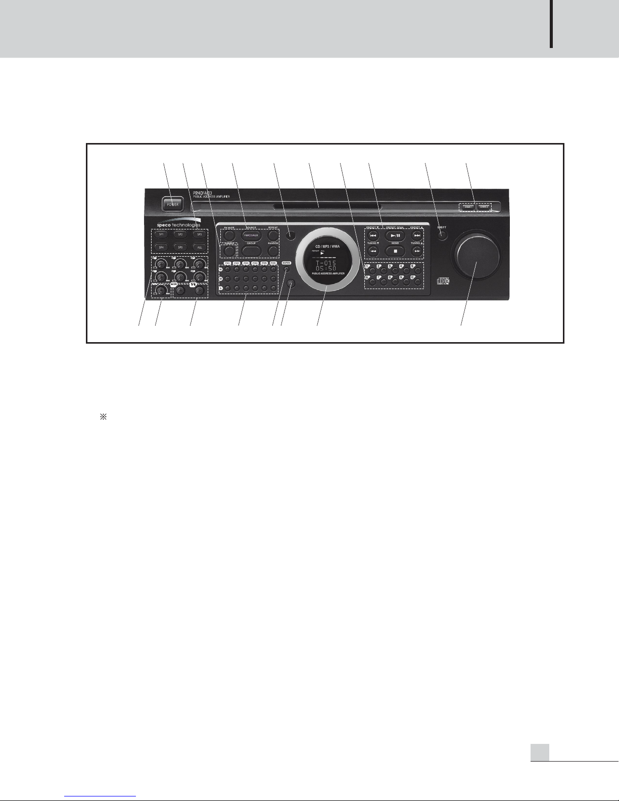
Front Panel
1. POWER SWITCH
Pressing this switch turns the unit on, and the VFD (Vacuum Fluorescent Display) will show the status of the
unit. Pressing again will turn the unit off. If the AC power is connected, the unit will enter Standby mode, and
the “POWER” LED will light.
When the protection circuitry is activated, the “POWER” LED will blink.
This indicates that the unit is not operating normally. This is typically due to rare cases of overheating, overload or output line shorts. Please check the input and output conditions of the amplifier in this event. The
unit will automatically turn the power on and check the protection state 1 minute after the protection
circuitry has been activated. If you want to release the protection manually, press the POWER switch.
2. SPEAKER SELECTOR
These switches are used to select speaker output zones. The “All” button will select all speaker zones (SP1,
SP2, SP3, SP4 and SP5). 8Ω output is not controlled by the speaker selector buttons.
3. DIMMER BUTTON
Press this button to change the brightness of the display.
4. FM /CD/AUX BUTTON
1) FM MUTE Button
This button can be used to mute the FM output while searching for a station with a good signal.
2) FM/CD/AUX select button
This button will allow you to toggle between the 3 possible sources.
3) REPEAT Button
Press this button to repeat a track or tracks on a CD.
4) GROUP Button
Press this button to select a folder on an MP3 disk.
5) RANDOM Button
Press this button to randomly play CD tracks.
34 78 9 1012 5 6
15 16 17 1814131211
Page 8

PUBLIC ADDRESS AMPLIFIER
6
P120FACD/P240FACD
5. IR WINDOW
6. DISC INSERT SLOT
Insert a CD or CD-ROM here.
The player will automatically accept the CD as it’s entered into the slot.
7. NUMERICAL BUTTONS
Press the track number buttons to skip to a specific track on a CD.
Press the preset number button to go to a specific preset FM station.
8. CD / FM RELATED BUTTONS
1) (Play/Pause) / PRESET SCAN Button
In CD function - Play or Pause Button.
In FM function - Preset Scan Button.
2) , / PRESET , PRESET Button
In CD function - Backward Skip and Forward Skip Button.
In FM function - Preset Down and Preset Up Button
3) (Stop) / MEMO Button
In CD function - Stop Button.
In FM function - Memory Button
4) , / TUNING , TUNING Button
In CD function - Backward Search and Forward Search Button.
In FM function - Tuning Down and Tuning UP Button
9. EJECT BUTTON
Press this button to eject the CD from the unit.
10. CHIME BUTTON
CHIME 1 Button : Press this button to activate the 2 tone chime.
CHIME 2 Button : Press this button to activate the 4 tone chime.
11. CHANNEL VOLUME
Controls the individual volume level of Mic Channels.
12. SOURCE VOLUME
Controls the volume level of the selected source.
13. TONE CONTROL
Adjust Bass or Treble to cut(decrease) or boost(increase) the frequency of 100Hz or10kHz.
14. MIC TONE CONTROL OF CH1 ~ CH6
Controls High (8kHz), MID (1kHz), or LOW (250Hz) tones.
First, press ‘ENTER’ button to enter into EQ Mode, then select the tone of the channel you want, adjust the MIC
Tone Control Volume and press ‘ENTER’ to save and exit the EQ Mode. Please refer to the ‘CHANNEL EQ
SETUP’ section (page 14).
Page 9

PUBLIC ADDRESS AMPLIFIER
7
P120FACD/P240FACD
15. EQ MODE AND SETUP BUTTON
This button is used for entering the EQ mode and to enter the SETUP mode.
Please refer to the “CHANNEL EQ SETUP” section (page 14) and “SETUP Mode” section (page 15) for details.
16. MIC CHANNEL TONE CONTROL VOLUME
Adjust the level of the 3-Band MIC Tone.
To adjust the level of a tone, press ‘ENTER’ button to enter into the EQ Mode.
Press the tone button (H, M, or L) of the channel you want and adjust the tone control volume and then press
the ‘ENTER’ button to save and exit the EQ Mode.
Please refer to the ‘CHANNEL EQ SETUP’ section (page 14) for details.
17. DISPLAY
VFD (Vacuum Fluorescent Display) displays the state of the operation of the unit.
18. MASTER VOLUME
Adjust the signal level of the post output and the speaker outputs.
Page 10

PUBLIC ADDRESS AMPLIFIER
8
P120FACD/P240FACD
Rear Panel
Rear Panel
1. AC INLET
Connect the standard three-pin AC cable to this inlet.
2. DC INPUT TERMINALS
When AC power supply and DC 24V are connected at the same time, the AC power will take priority and the
DC power will not be used.
When the AC power is off, the unit will be operated by DC 24V.
When the DC 24V is discharged below 19.2V, the unit will go into Standby mode.
3. SPEAKER OUTPUT TERMINALS
These terminals are for connecting speaker wire. Only connect speakers for which the total sum of the
impedance is equal to or higher than the rated output impedance. Only the 70V terminals (Speaker zones 1-5)
controlled by the speaker selector on the front panel.
Be sure the total sum of speaker output, after factoring in a safety margin, does not exceed 120W for the
P120FACD, and 240W for the P240FACD.
4.
RS-232C CONTROL
The unit can be controlled by AMX or CRESTRON System with this RS-232C interface.
The maximum cable length is about 15m.
RS-232 PIN OUT Spec
PIN
Purpose
1
Not Used2Receiver3Transmit4Not Used5Ground
6~9
Not Used
5 768910111213144321
15 16 17
18
Page 11

PUBLIC ADDRESS AMPLIFIER
9
P120FACD/P240FACD
5. OPTIONAL EXTERNAL PAGING UNIT TERMINAL
This unit has the ability to be controlled via an external, zoned paging microphone, which will be available as
a future option. For reference, here is the pin chart:
6. MUSIC ON HOLD VOLUME
Control the volume level of Music On Hold.
7. EM (EMERGENCY) TERMINALS
When EM switch is connected and pressed in fire or in other emergency cases, EM broadcasting stored in
VOICE IC is outputted. When EM is activated, all the other signals are muted.
8. EXT CHIME
Use these terminals to activate the chime externally.
When the EXT CHIME is selected the ‘CHIME1’, 2 tone chime is activated.
9. EXT MUTE
Use these terminals to mute the signal of the unit externally.
Only EM, RM or Tel-In has priority over the EXT Mute.
10. TEL IN TERMINALS
These terminals can be connected to a telephone exchange system.
When the telephone signal is input, all the other input signals are muted.
11. MUSIC ON HOLD TERMINALS
These terminals output the internally selected source. This is a balanced output.
12. FM ANTENNA
Connect the FM antenna here. Please mount the antenna in an area with good reception.
13. MIC 1 / 2 PRIORITY
Press these switches to give priority to channels 1 or 2.
14. PHANTOM POWER SWITCH
These switches turn the phantom power supply on and off for each channel. When the switch is pushed in,
24V DC power is supplied to pins 2 and 3 of the XLR jack. Use phantom power when using a condenser
microphone which requires an external power supply.
Pin 1: Remote amplifier input signal hot(+) Pin 8: Remote control 5(Speaker 5)
Pin 2: Remote amplifier input signal cold(–) Pin 9: Remote control ground
Pin 3: Signal ground Pin 10: DC +24V
Pin 4: Remote control 1(Speaker 1) Pin 11: Chime Input
Pin 5: Remote control 2(Speaker 2) Pin 12: NC
Pin 6: Remote control 3(Speaker 3) Pin 13: NC
Pin 7: Remote control 4(Speaker 4) Pin 14, 15: NC
Page 12

PUBLIC ADDRESS AMPLIFIER
10
P120FACD/P240FACD
NOTE: It is safe to connect most modern dynamic
microphones to the microphone inputs when
phantom power is activated. However, some
older ribbon microphones may be damaged
by phantom power and certain unbalanced
line level devices may malfunction or
produce an audible hum when phantom
power is turned on. Use the phantom power
only when using a condenser microphone.
Also, if you activate the phantom power with
the volume turned high, it could produce an audible popping sound.
15. AUX IN
This is the unbalanced input. This input can be used to connect a tape player or other sound sources.
Input Level : -30dBV ~ +6dBV.
16. PRE/POST OUT
PRE OUT : This is the unbalanced output. This output can be used to record the signal from the unit.
The output level is not controlled by the master volume.
Output Level : 0dBV.
POST OUT : This is the unbalanced output. This output can be used to monitor the signal with a monitor amplifier.
The output level is controlled by the master volume.
Output Level : 0dBV.
17. MIC INPUT: CH1 – CH6 (or LINE INPUT)
These inputs are suitable to receive signals from microphones. XLR inputs are balanced.
Input level: -60dBV ~ -16dBV
When another line level source is connected to one of these terminals, adjust the trim volume to the -16dB
position. The phantom power must be off or the line level source could be damaged.
18. INPUT GAIN CONTROLS (TRIM VOLUME)
These are the trim volume controls for each much input to control the input gain.
When adjusting the input gain, make sure that the levels are not set too high or it may cause noisy or
distorted output.
MIC XLR JACK
PIN 1 Ground
PIN 2 Hot(+)
PIN 3 Cold(-)
Page 13

PUBLIC ADDRESS AMPLIFIER
11
P120FACD/P240FACD
Connecting Speakers
Connecting Speakers
Before connecting speakers, disconnect the AC power cable. Note the proper connecting terminals as shown
below. Make certain that the total impedance is not less than the rated impedance indicated.
NOTE : Be sure that total impedance is not less than the rated impedance. (See upper chart.)
Do not connect the low impedance speaker to the high impedance terminals.
WARNING : Extreme care must be exercised when connecting high-impedance systems, as potentially
hazardous voltages may be present at these terminals.
Do not install this equipment in a confined space with less than adequate ventilation.
HIGH IMPEDANCE SPEAKER INSTALLATION
Total power sum of all zones (1~5) must not exceed the rated power.
P120FACD : 120W, P240FACD : 240W
Do not use 8Ω speaker terminal and high impedance speaker terminals (1~5) at the same time.
8Ω (LOW IMPEDANCE) SPK1~5 (HIGH IMPEDANCE)
P120FACD 31V/8Ω (120W) 70V/41Ω
P240FACD 43.8V/8Ω (240W) 70V/21Ω
Model Name
Output
Page 14

PUBLIC ADDRESS AMPLIFIER
12
P120FACD/P240FACD
FM Operation
FM Operation
- MANUAL / AUTO TUNING METHOD
1. Choose the FM function using the FM/CD/AUX button.
2. Select the station you want with the TUNING buttons.
Auto Tuning : Hold the TUNING button for 2 seconds in either direction and the unit will automatically
search for a station with a strong signal. When complete, the VFD will display “TUNED”
and you will be able to listen to the station.
Manual Tuning : Quickly press the TUNING button in either direction and the frequency will change by
one step. Repeat until the desired station is reached. When complete, the VFD will
display “TUNED” and you will be able to listen to the station.
- MEMORY / RECALL STATION
1. Choose the station you want via the TUNING buttons.
2. Press the MEMO button and the VFD will display “MEMORY” for 10 seconds.
3. Choose the number on which you want to save the station from the numerical buttons, and the VFD will
display that number.
4. Repeat the above procedures for each station you want to save. Up to 40 stations can be saved to memory.
5. Choose a number with a saved station to recall that station. You can also use the PRESET buttons to scroll
through the saved station.
- FM ANTENNA INSTALLATION
Please find a spot where reception is good and mount the antenna.
The tuning quality may suffer near cities, industrial complexes, broadcast towers or power lines.
Page 15

PUBLIC ADDRESS AMPLIFIER
13
P120FACD/P240FACD
CD Operation
CD Operation
- PLAYING
1. Choose the CD function via the FM/CD/AUX select button.
2. When there is no disc, the VFD will show “NO DISC.”
3. Put a disk in the slot. The player will load the CD automatically as you begin to put it in.
4. Wait until the CD read the contents of the CD.
5. Press the play button ( ) to play the CD.
6. Press the stop button ( ) to stop playing.
7. Please use only standard size Compact Disks. DO NOT USE MINI DISKS.
- PLAY / PAUSE FUNCTION
1. When a disk is loaded, it will read the CD and go into standby mode. It is capable of displaying up to 499
tracks.
2. Press the Play/Pause button to play, and press it again to pause.
NOTE : When a disk is severely scratched, corrupt or in an unreadable format, it will be automatically
ejected. If this regularly happens with a specific disk, it is not unit failure and please check the disk for
any of these circumstances.
- EJECT
1. Press the EJECT button to remove the disk.
2. The disk will eject regardless of the current state of the player.
- REPEAT FUNCTION
REPEAT 1
1. Repeats a single track
2. Pres the REPEAT button before or during play and it will repeat the current track continuously.
REPEAT ALL
1. Repeats all tracks.
2. Press the REPEAT ALL button before or during play and it will repeat all of the tracks continuously. The
VFD will indicate “REPEAT ALL” in this case.
- RANDOM FUNCTION
1. Press the RANDOM button before or during play to play through all tracks non-sequentially.
2. When activated, the VFD will display “RANDOM”.
3. Use in conjunction with the REPEAT button to randomly repeat the CD.
4. Pressing the RANDOM button again will cancel RANDOM mode.
- GROUP UP/DOWN FUNCTION
1. The GROUP button can only be used if the MP3CD has saved folders on it.
2. Press the group button during play. The VFD will display “GROUP.” Press the
(SKIP) buttons to
move to the next group folder to play from.
3. Press the GROUP button again to cancel the group function.
Page 16

PUBLIC ADDRESS AMPLIFIER
14
P120FACD/P240FACD
Channel EQ SETUP
Channel EQ SETUP
1. Press the ENTER button to enter into the EQ mode
2. Choose the frequency H, M or L of the channel you want among .
3. Adjust the tone level with the volume, .
4. Repeat the above procedure 2~3 for the other channels.
5. Press the ENTER button, to exit the EQ modes.
You will auto save and exit the EQ mode if no key is pressed for 10
seconds.
Please refer to the below example.
EX>CH1 EQ SETUP (HIGH -2dB, MID : 10dB, LOW: 0dB)
1. Press the ENTER button, to enter into the EQ Mode.
2. Press the H of the CH1.
3. Adjust the tone volume to set it to -2dB.
4. Press the M of the CH1.
5. Adjust the tone volume to set it to 10dB.
6. Press the ENTER button to save and exit the EQ mode.
Be sure the default EQ level is 0 dB.
Page 17

PUBLIC ADDRESS AMPLIFIER
15
P120FACD/P240FACD
SETUP Mode
SETUP Mode
Press the H of CH1 and CH6 at the same time ( ) to enter into
the SETUP mode. Turn the volume, to enter into each setup
function, MIC 1, 2 Mute level, Tel-In volume, Chime volume, etc.
Press the H button of the CH6, to exit the current setup function
or setup mode.
Page 18

PUBLIC ADDRESS AMPLIFIER
16
P120FACD/P240FACD
1. MIC PRIORITY (CH1,CH2)
Turn the volume, to choose ‘SET MIC1(MIC2) MUTE LVL’, Press ENTER, .
Choose MIN, MID, or MAX with the volume
, Press ENTER, .
- MIN : Attenuate level of the other channels by -6dB.
- MID : Attenuate level of the other channels by -12dB.
- MAX: Mute the other channels.
To use the MIC Priority function, press the MIC Priority Switch on the rear panel
2. TEL-IN LEVEL
You can adjust the TEL-IN level. Turn the volume, to choose 'TEL-IN LEVEL', Press ENTER, .
(VOL: 0(MIN) ~ 31(MAX), DEFAULT: MAX)
3. CHIME LEVEL
You can adjust the chime level. Turn the volume, to choose 'CHIME LEVEL', Press ENTER, .
Adjust the level with the volume .
(VOL: 0(MIN) ~ 31(MAX), DEFAULT: MAX)
4. BEEP SOUND
Beep sound when you press a button on the front panel.
You can set it on or off. Turn the volume, to choose 'BEEP SOUND', Press ENTER, .
Choose ON or OFF, Press ENTER, .
- ON: Beep sound.
- OFF: Beep does not sound.
5. IR REMOTE CONTROL
You can set the optional IR Remote Control function on or off. Select IR REMOCON from the menu and press
ENTER . Choose ON or OFF and press ENTER again .
- ON: Enable the optional IR Remote Control function
- OFF: Disable the optional IR Remote Control function
6. KEY LOCK FUNCTION
All the key inputs except Power button can be locked by the KEY LOCK function.
Turn the volume, to choose 'KEY LOCK', Press ENTER, . Choose Lock or Unlock, Press ENTER, .
7. EM BROADCASTING: VOLUME SETUP FUNCTION
The is to set up ‘output volume level’ of an amplifier in case of EM broadcasting. At an initial setup, after
select EM broadcasting sourcce from no. 8 and give an input to EM terminal. And then, adjust an appropriate
volume with ®Í volume controller. (VOL: 50~70, DEFAULT: 60)
8. SYSTEM INFORMATION
Choose SYSTEM INFO and press ‘ENTER’, . You can check the current firmware version.
If you do not press any key for 10seconds, you will exit the SETUP mode.
Page 19

PUBLIC ADDRESS AMPLIFIER
17
P120FACD/P240FACD
C
Applications
Applications
TELEPHONE
INTERFACE
TIMER
OFF PLAY
HIGH DENSITY 1-BIT D/A CONVERTER
1 2 3 4 5
5DISC AUTOMATIC DISC LOADING SYSTEM
PROG
TRACK
OPEN/CLOSE
DISC SKIP
DISC SELECTOR
1 2345
COMPACT
DIGITALAUDIO
1 2 3
REPEAT TIMER DISC INTRO
PROG / REV
RANDOM REPEAT ALL 1 DISCS
INDEX INTRO
RANDOM
4 5 6
7 8 9
10 11 12
13 14
-SKIP-SEARCH STOP/CLEAR PLAY/PAUSE
PRE A MPLIF IER
PP-9113
10
5
0
MIC 1 MIC 2 MIC 3 MIC 4 MIC 5 MIC 6 PHONO CD AUX DECK TUNER
D PL
ON OFF
POWER
DECK
POWER
10
CHIME
BASS
TREBLE
MIXER
ON
5
0
0
-12
-12
+12
+12
10
10
OFF
0
MASTER
DECKCONTROL INTERFACE
Page 20

PUBLIC ADDRESS AMPLIFIER
18
P120FACD/P240FACD
Block Diagrams
Block Diagrams
Page 21

PUBLIC ADDRESS AMPLIFIER
19
P120FACD/P240FACD
Specifications
Specifications
P120FACD P240FACD
AUX INPUT(AUX IN @1kHz, 8Ω Load Output)
Rated Output Power 120W 240W
Input Sensitivity -10dBV/10kΩ
S/N, AES-17 WTD ≤ -80dB
Tone Control(BASS:100Hz, TREBLE:10kHz)
±10dB
Frequency Response (1W Power Output, ±3dB)
90Hz-18kHz
T.H.D. <1%
MIC 1 ~ 6 Input (MIC IN @1kHz, PRE OUT)
Input Sensitivity -60dBV ~ -16dBV/10kΩ
S/N, A-WTD ≤ -60dB
Frequency Response (±3dB) 120Hz-10kHz
Phantom Power +24V DC
Remote IN (Remote IN @1kHz, PRE OUT)
Input Sensitivity -60dBV/10kΩ
S/N, A-WTD ≤ -50dB
Frequency Response (±3dB)
120Hz-10kHz
TEL IN (TEL IN @1kHz, PRE OUT)
Input Sensitivity -10dBV/10kΩ
S/N
, A-WTD
≤ -65dB
Frequency Response (±3dB)
330Hz-3kHz
CD (Test CD 0dB, 1kHz @ PRE OUT)
S/N, A-WTD < -85dB
Frequency Response (±3dB)
80Hz-18kHz
TUNER (FM, 22.5kHz, MOD @ PRE OUT)
S/N, A-WTD < -60dB
Frequency Response (±3dB)
100Hz-14kHz
PRE OUT (MIC1~6, AUX IN TEL IN, Remote IN)
Output Level 0dBV/600Ω
T.H.D < 0.5%
POST OUT /Output Level 0dBV/600Ω
Operating Temperature -10°C ~ +40°C
Power Source 120VAC/60Hz, 24VDC
Power Consumption(1/8 power) 90W
Weight 10kg/22.7lb 11kg/24.3lb
Dimensions 420(W) x 132(H) x 380(D)mm/16.5(W) x 5.2(H) x 15(D)in
* Specifications and design subject to change without notice.
* 0dBV=1V
Page 22

PUBLIC ADDRESS AMPLIFIER
20
P120FACD/P240FACD
Service
Service
Procedures
Take steps to insure the problem is not related to operator error or other products within the system. Information
provided in the troubleshooting portion of this manual may help with this process. Once it is certain that the
problem is related to the product contact your warranty provider as described in the warranty section of this
manual.
Warranty and Repair
Warranty and Repair
We warranty this product to be free from any manufacturing or material defects for five (5) years from the date
of purchase. This warranty will not extend to any products which have been subjected to misuse, neglect,
accident, or improper installation, used in violation of instructions furnished by us; or to units which have been
repaired or altered outside of the factory. This limited warranty does not apply to broken cases, batteries, or
other physically damaged parts. Unless requested, the company will replace and return all merchandise in the
packaging in which it was received. This warranty is in lieu of all expressed warranties, expressed or implied,
and of all obligations or liability on our part, and we neither assume nor authorize any representative or other
person to assume for us any obligation or liability. In no event shall we be liable for incidental or consequential
damages arising from the use of the product, or for any delay in the use of this product do to causes beyond our
control. Some states do not allow limitations of how long an implied warranty lasts and/or do not allow the
exclusion or limitation of consequential damages. The above limitations on implied warranty and consequential
damages may not apply to you. This warranty gives you specific legal rights. You may have other rights which
vary from state to state.
Page 23

21
P120FACD/P240FACD
Page 24

MADE IN KOREA
July 2009 124216
200 New Highway
Amityville, NY 11701
Phone 631.957.8700 • Toll Free 1.800.645.5516
www.specotech.com
 Loading...