

Page 1
ONSIP OPTZ33D5W
Page 2
OOPPTTZZ3333DD55W
W
OOwwnneer
r
’
’
ss mmaannuuaal
l
Rev.1.2 Aug. 2012
2 of 31
This unit should be installed by trained
personnel.
Immediately stop using when the product
emits smoke or abnormal heat.
Never install the product in area exposed to
oil or gas.
Never install the product on a ceiling that
cannot hold its weight.
Never touch the power cord with wet hands.
Clean only with dry cloth.
Never use the product in extremely high or
low temperature condition.
Never drop, hit, strongly nor vibrate the
product.
Never expose the product to direct sunlight
or severe ray.
Never touch the front glass of the product.
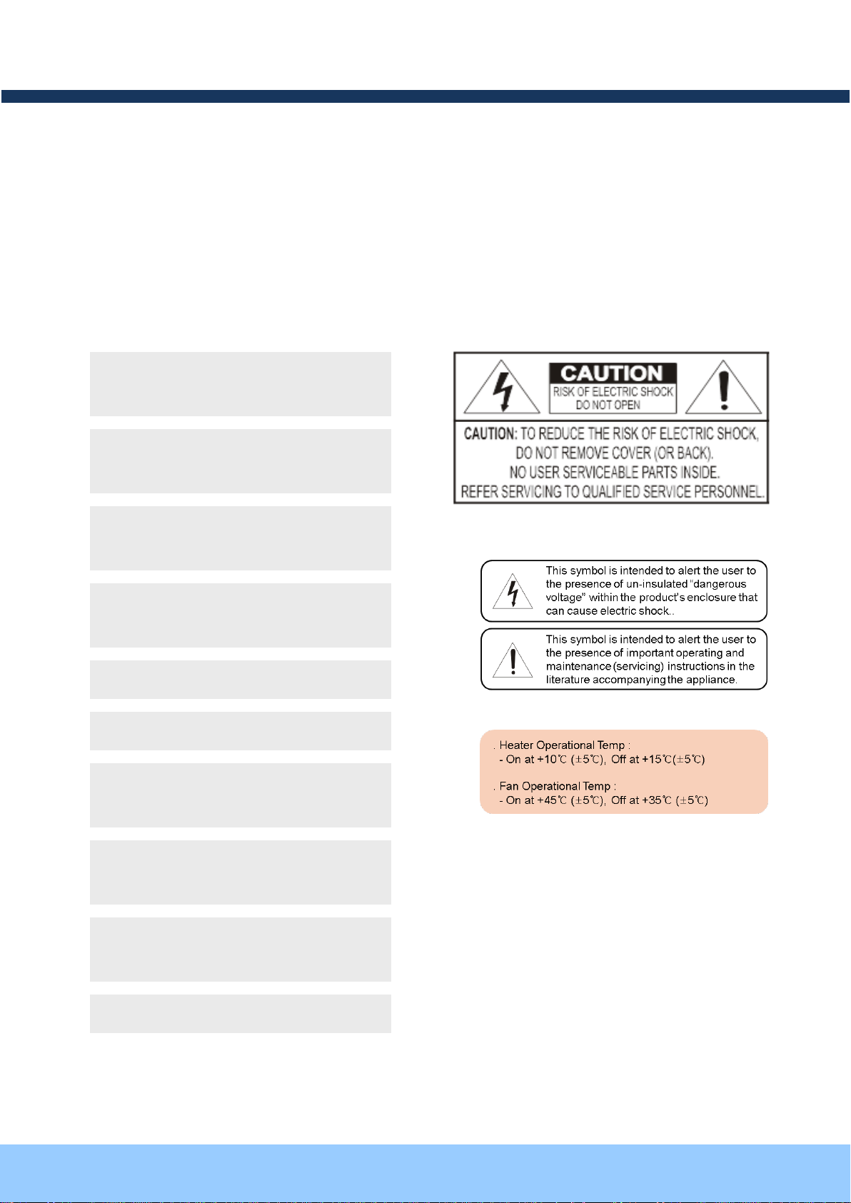
Warnings & Cautions
If you fail to read this information and handle the product incorrectly, faulty or malfunction as well as
death or serious injury may occur.
Page 3
OOPPTTZZ3333DD55W
W
OOwwnneer
r
’
’
ss mmaannuuaal
l
Rev.1.2 Aug. 2012
3 of 31
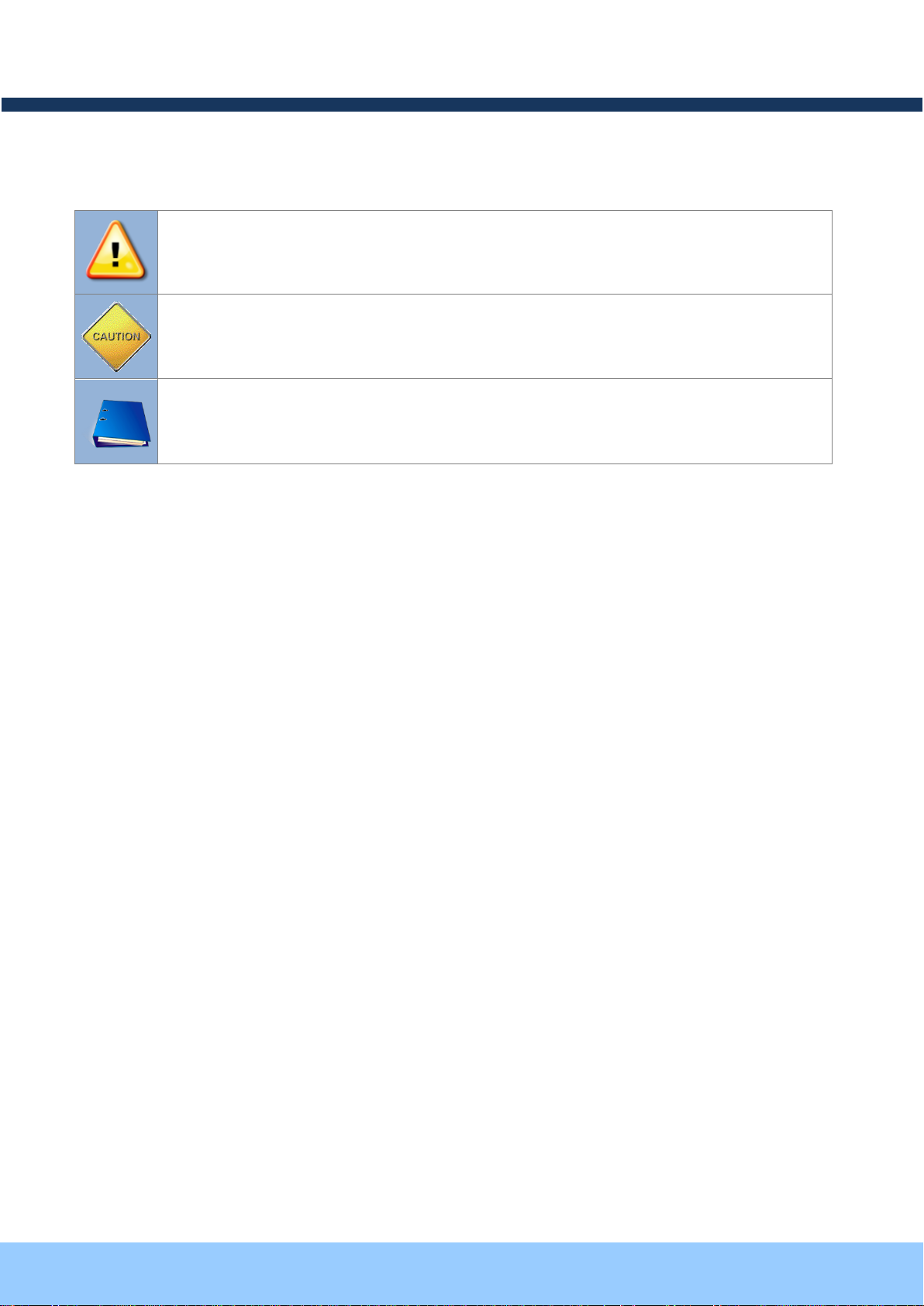
Warning: Death or Serious Injury will occur without following Warning.
Caution : Operational Problem(Faulty & Malfunction) will occur without complying with Caution
Reference : Technical Information for Users
Graphic Indicators:
Page 4

OOPPTTZZ3333DD55W
W
OOwwnneer
r
’
’
ss mmaannuuaal
l
Rev.1.2 Aug. 2012
4 of 31
Table of Contents
Table of Contents ............................................................................................... 4
1 Introduction ................................................................................................... 5
1.1. Overview of OPTZ33D5W .............................................................................................. 5
1.2. Features of OPTZ33D5W ............................................................................................... 5
1.3. Specification of OPTZ33D5W ......................................................................................... 7
2 Product Description ...................................................................................... 8
2.1. Package Contents .......................................................................................................... 8
2.2. Preview .......................................................................................................................... 8
2.3. Physical Description ................................................................................................ ....... 9
2.4. Detailed Specification of Analog Camera Module & PTZ ............................................... 11
3 Bracket Installation ..................................................................................... 13
4 Installation .................................................................................................. 17
4.1. Required System Specification ......................................................................................17
4.2. Quick Installation Guide ................................................................................................18
4.3. Install Speco-NVR .........................................................................................................19
4.3. Remote Connection to IP Camera .................................................................................21
4.4. Connection through Speco-NVR ...................................................................................22
5 Trouble Shooting ........................................................................................ 24
5.1. No Video on Viewer ..............................................................................................................24
5.2. Windows Vista and Windows 7 User for Record & Capture Problem ....................................25
5.3. Technical Support ..........................................................................................................28
6 Appendix .................................................................................................... 29
6.1. Sensor Input for Alarm & Relay Output .................................................................................29
6.1.1. “ALARM” Port for Sensor Input .................................................................................................... 29
6.1.2. “AUX” Port for Relay Output ......................................................................................................... 30
6.1.3. Connection of Sensor and Relay Output Device .......................................................................... 31
Page 5

OOPPTTZZ3333DD55W
W
OOwwnneer
r
’
’
ss mmaannuuaal
l
Rev.1.2 Aug. 2012
5 of 31
11..11.. OOvveerrvviieeww ooff OOPPTTZZ3333DD55WW
11..22.. FFeeaattuurreess ooff OOPPTTZZ3333DD55WW
1 Introduction
OPTZ33D5W, as a state-of-the-art Speed Dome Network Camera based on integrated Embedded Software
technologies such as H.264 & MJPEG, G.726 & PCM Video & Audio Compression, Embedded Web Server,
Embedded Streaming Server, various Network Protocols, transmits synchronized video and audio data in real
time with D1 resolution at full frame rate through IP Network as well as supports bi-directional audio
communication by allowing transmission of audio from Client PC to OPTZ33D5W.
OPTZ33D5W, with completed Integration with analog CCTV camera, Digital and network technology, is
applicable for various sectors such as Security, Remote Monitoring, Remote Education, Simple Video
Conference as well as Internet Broadcasting System etc.
High Image Quality with outstanding H.264 Video Compression technology
D1 Resolution @ Max 30 FPS(NTSC) and Max 25 FPS(PAL)
Full D1 Resolution with De-Interlaced Filer
Simultaneous transmission of 1 Ch Video/Audio Data via 1 Communication Channel
Intelligent Bit Rate Control against flexible Network Configuration
Embedded Streaming Server and Embedded Web Server
RoHS
Filter Changeable(ICR) for Day(Color) & Night(B/W)
IP66
12x Zoom (12x Optical, 16x Digital)
360° endless rotation
Software Controller
Clear Image with 530TV Lines(B/W:580TV Lines)
SDNR for clear identification under low illumination
PAN / TILT Speed with Max 250°/Sec
Various Network Protocol
2 Alarm Sensor Inputs / 1 Relay Output
Remote Administration
Page 6

OOPPTTZZ3333DD55W
W
OOwwnneer
r
’
’
ss mmaannuuaal
l
Rev.1.2 Aug. 2012
6 of 31
Hot Keys
This camera supports various hot key
functions for ease of control by other
controllers or DVRs.
Various Surveillance Functions
Auto Scan continuously repeats movement between
two preset positions with various speed and dwell time.
8 Group Tour: Up to 8 Programmable Group tours
are supported. Each group can be configured to have up
to 60 preset positions with different speed and dwell time
165 Preset positions: Up to 165 programmable
preset positions. Each preset position can be labeled by
up to 16 characters
8 Patterns: up to 8 user-defined patterns. Each pattern
can last up to 60 seconds and can be named with up to
16 characters. Total of 480 second of pattern monitoring
is possible.
8 Sectors: Up to 8 user-defined sectors. Each sector
can be labeled by up to 16 characters
4 Privacy Masking Zones: Up to 4 user-defined
privacy masking zone. Each zone can be labeled by up
to 16 characters
2 Alarm input and 1 relay out: 2 alarm inputs and 1
relay outputs that can be matched with preset, tours,
and patterns for versatile monitoring functions.
High speed Pan & Tilt movement
Maximum speed for the panning and tilting are 350° /sec
and 250° /sec, respectively, for preset movement. The
high speed will enable quick movement to the spot you
want to watch.
150°/S – Manual Operation speed
This camera provides up to 150°/sec of manual speed
and it’s adjustable from 100°/sec to 150°/sec
1/4” Sony Super HAD CCD
Sony Super HAD CCD for excellent sensitivity and low
smear levels.
Multiple language support
Intelligent Pan/Tilt Controlling
Pan and tilt speed is adjusted in connection with zoom
factor.
12X Zoom Mini Speed Dome
12X Optical Zoom with 16X digital zoom
±0.02° dome system accuracy with 1/4
micro step
By adopting 1/4 micro step and twin gear system, the dome
camera achieved 0.1° rotational accuracy. It provides excellent
precision for delicate control such as preset positions.
360° Endless Rotation
Preset position compensation
It minimizes the effect of low frequency vibration caused by
wind or other impact for maintaining precise positioning. It is
useful for outdoor surveillance and traffic monitoring
applications.
Over 250°/Sec Preset Speed
Polarity Protection of Power (DC12V)
This protection function prevents the power board from being
out and trouble when power source falsely connects to the
power terminals.
Protected RS485 terminals. (Against
misconnection of the power line)
RS-485 circuit is protected against false connection of the power
source for ensured communication channel.
Filter changeable True Day/Night (ICR
Block Filter)
Automatic IR cut filter ensures near-true color video for day time
while providing quality B/W video under low illumination. The
efficiency of the monitoring can be improved by using this
feature used together with DSS (Digital Slow Shutter).
Indoor / Outdoor applications
Aluminum case and PC cover (IP66)
Elegantly designed aluminum body and Poly Carbonated dome
cover provide weather proof environment to the internal
modules. (IP66 Rated)
Detailed Features of Speed Dome Camera (Analog Camera Module, PTZ)
Page 7

OOPPTTZZ3333DD55W
W
OOwwnneer
r
’
’
ss mmaannuuaal
l
Rev.1.2 Aug. 2012
7 of 31
11..33.. SSppeecciiffiiccaattiioonn ooff OOPPTTZZ3333DD55WW
Class
Description
Video
Compression
H.264/MJPEG
Resolution
D1, Half-D1, CIF, QCIF
Audio
(Bi-directional)
Up Stream
G.726 32 Kbps
Down Stream
PCM 64 Kbps
Network
Interface
RJ-45, 10/100 Mbps
Access Network
Static, DHCP, PPP/PPPoE
Protocol
IPv4/6, TCP, UDP, IGMP, ICMP, ICMPv6 etc.
I/O
RS-485
RS-485 for external PTZ Device
Sensor
2
NC, NO Selectable
Relay Output
1
Alarm or Remote ON/OFF Control
RS-232C
Factory Default
Mic/Line In
Selectable on Admin Page
Line Out
1V p-p Audio Output
CVBS Output
Analog Video Output for convenient installation
Power
DC In
12V DC Adaptor (2A)
Installation Type
Stand Mount
Motion Detection
Optional Shape & Sensitivity for 3 Regions
Management & Configuration
Remote F/W Upgrade via IP Network
Client/Viewer
Web Viewer
Simple Access via Internet Explorer
NVR-Pro
CMS Software
3rd Party CMS
Contact to Speco
Dynamic IP
DDNS support
Supported by Speco’s Management Server
Security Management
User ID & Password Protection, IP Filtering, Audio per user
and Bi-directional audio communication configuration control
Time Configuration
Management
Sync to PC
Sync to PC Time
Manual
Manual Configuration
Internet Time Server
Sync to Time Server
DLS
Summer Time Configuration
SDK support
Active-X
HTTP
Page 8
OOPPTTZZ3333DD55W
W
OOwwnneer
r
’
’
ss mmaannuuaal
l
Rev.1.2 Aug. 2012
8 of 31
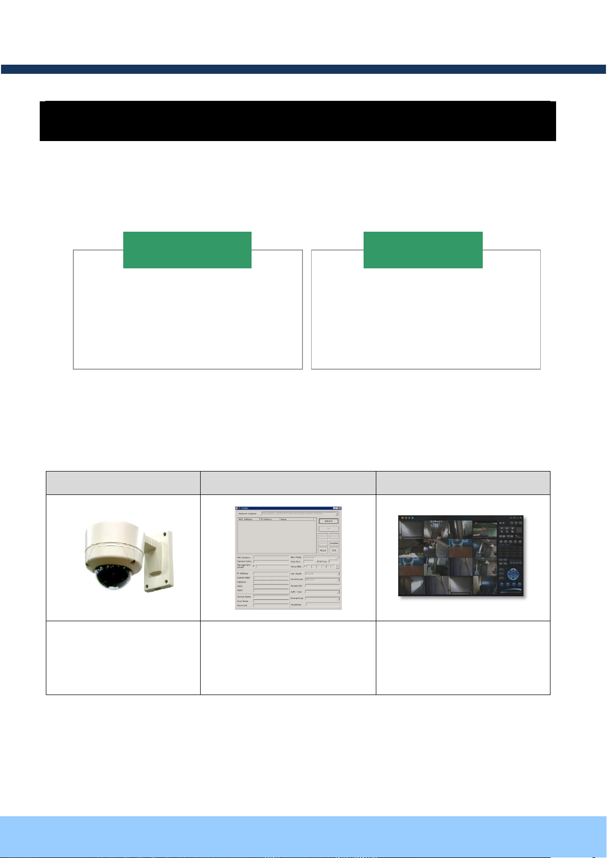
22..11.. PPaacckkaaggee CCoonntteennttss
22..22.. PPrreevviieeww
OPTZ33D5W
Speco-NVR
H.264 Speed Dome
Network Camera.
IP Assignment Program
PC based Client for
monitoring/storing Video/Audio
transmitted form OPTZ33D5W
(Max. 64CH supported)
1. Camera Main Body
2. CD (Manual, Software)
3. Screw (Ø 4x16 : 5EA)
4. Terminal Block (5PIN : 2EA)
OPTZ33D5W
1. Wall Mount Bracket
2. Adaptor
Optional Items
2 Product Description
Open the package and check if the followings are included;
Note: Standard DC Adaptor can be purchased from Speco.
ONSIP-Installer
Page 9
OOPPTTZZ3333DD55W
W
OOwwnneer
r
’
’
ss mmaannuuaal
l
Rev.1.2 Aug. 2012
9 of 31
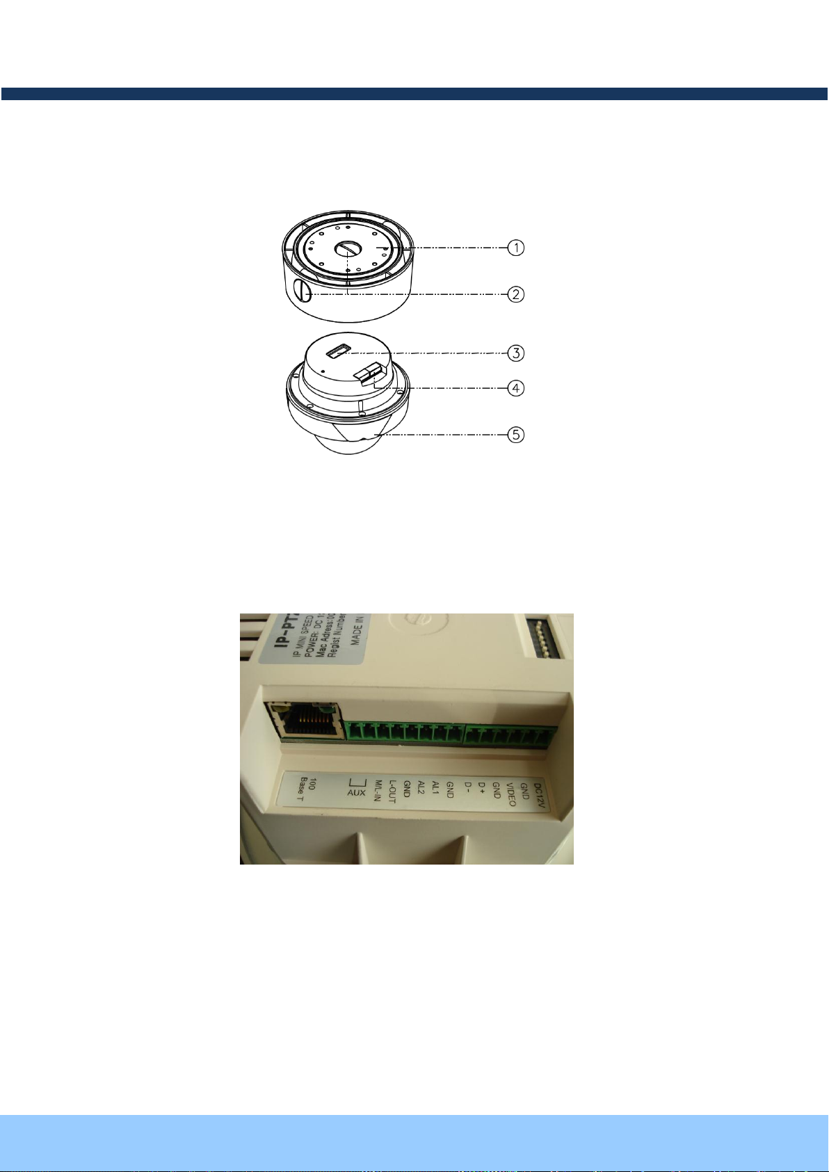
22..33.. PPhhyyssiiccaall DDeessccrriippttiioonn
① Surface Mount Adaptor
② Cap Screw
③ DIP Switch
④ Terminal Block
⑤ Main Body
2.3.1. Bottom View& Connection
Detailed Terminal Block View of OPTZ33D5W
- Network Connection
10/100 Base T: As Ethernet Port, connects OPTZ33D5W to LAN with 10Mbps or 100Mbps via RJ-45.
Page 10

OOPPTTZZ3333DD55W
W
OOwwnneer
r
’
’
ss mmaannuuaal
l
Rev.1.2 Aug. 2012
10 of 31
PIN
Description
AL1, AL2
(Alarm)
- 2 Alarm Inputs
- Connect external alarm sensors such as the infrared, heat, magnetic sensor
to network camera.
- Connect one end of the alarm device to GND.
- Sensor type(Normal Open or Normal Close) can be selected using Virtual
System Controller (Keyboard Emulator) in Speco-NVR
AUX
- 1 Relay Output
- Use the two pins to connect the alarm annunciating device such as sirens,
flashing light, etc., to network camera.
- Please refer to the section 6.1 for more detailed description.
GND
- Ground
D+, D-
- RS-485 Connection Port
VIDEO
(Video Output)
- Composite video output from the camera.
L OUT
(Audio Output)
- Connect a speaker with amplifier. LINE OUT
- Audio/voice from client at remote site can be output through the line out
terminal in bi-directional audio mode of Speco-NVR.
M/L IN
(Microphone/
Audio Input)
- Connect external Microphone or audio to network camera.
DC12V
- Connect 12 Volt DC adaptor to this terminal for supplying power to the
network camera.
- Power adapter which is compliant to the specification for OPTZ33D5W
should be used. Misuse of power supply can cause damage to
OPTZ33D5W.
- SPECO assumes no responsibility for misuse of the power supply.
- The power can also be applied through the RJ-45 connector using
proprietary PoE injector or PoE adaptor supplied by Speco.
- When the power is applied through the RJ-45 connect, do not apply power
using DC12V pins.
Refer to the following table for PIN Configuration of Terminal Block.
Page 11

OOPPTTZZ3333DD55W
W
OOwwnneer
r
’
’
ss mmaannuuaal
l
Rev.1.2 Aug. 2012
11 of 31
22..44.. DDeettaaiilleedd SSppeecciiffiiccaattiioonn ooff AAnnaalloogg CCaammeerraa MMoodduullee && PPTTZZ
Class
12X A/F Camera Module
PAN/TILT
PAN Rotation Angle
360˚
PAN
Rotation
Speed
Manual
Max 150˚/Sec(64 Steps)
Preset
Max. 250˚ /Sec
TILT Rotation Angle
-2˚ ~ 90˚
TILT Speed
Manual
Max.150˚/Sec(64 Steps)
Preset
Max.250˚ /Sec
Minimum
Rotational Resolution
0.02˚
Functions
Preset
220 positions
Group Tour
Max. 8 Programmable Group Tours
(Max. 60 different Presets Steps for each Group Tour)
Auto Scan
Programmable Auto Scan
Pattern
16 character label identifiable 8 Programmable Patterns
Privacy Zone
4 Privacy Zones
Sector
16 character label identifiable 8 Programmable Sectors
Password Protection
Available
Alarm Input
2 (NC/NO Selectable)
Alarm Actions
Activate preset, Group scanning or output per alarm input
2.3.2. Dimension of OPTZ33D5W
Dimension of OPTZ33D5W
Page 12

OOPPTTZZ3333DD55W
W
OOwwnneer
r
’
’
ss mmaannuuaal
l
Rev.1.2 Aug. 2012
12 of 31
Aux Output
1 Relay Output
Auto Flip
ON / OFF
OSD Menu
English, Italian, Polish
Communication
RS-485
Power
Power Consumption
Max. 10W
Power Standard
DC12V, 3.35A
Camera
Module
Image Sensor
1/4" Super HAD CCD
No. of Pixels
NTSC
811(H) * 508(V) 410K
PAL
795(H) * 596(V) 470K
No. of
Effective
Pixels
NTSC
768(H) * 494(V) 380K
PAL
752(H) * 582(V) 440K
Horizontal Resolution
More than 500TV Lines
ZOOM
Optical
12x Optical Zoom
f=3.94 ~ 46.05mm (F=1.67~1.88)
Digital
16x (Total 192x with Optical)
Day/Night(ICR)
Auto/Day/Night
Min. Shooting Distance
0.35m(wide)/0.8m(Tele)
Digital Slow Shutter
2/4/8/16/24/32/64/128/ OFF
Min.
Illumination
Normal
Mode
0.2Lux/F1.6 (Color : 50IRE)
Night
Mode
0.04Lux/F1.6 (B/W : ICR On)
Luminance S/N Ratio
Higher than 52dB
Video Output
VBS:1.0Vp-p (sync negative), 75 ohm
BLC
ON / OFF
Flickerless
NTSC
ON / OFF (1/100)
PAL
ON / OFF (1/120)
White Balance
AWB/ATW/Indoor/ Outdoor
Page 13

OOPPTTZZ3333DD55W
W
OOwwnneer
r
’
’
ss mmaannuuaal
l
Rev.1.2 Aug. 2012
13 of 31
3 Bracket Installation
A. Installation Preparation
A-1: Ceiling Mount Type.
1. Fix the surface mount adaptor with 4 pcs of screws on the desired place(FIG.4).
2. When use Pipe, please note the standard size of Pipe.(FIG.5)
A-2: Set the DIP Switches as in the following picture.
Page 14

OOPPTTZZ3333DD55W
W
OOwwnneer
r
’
’
ss mmaannuuaal
l
Rev.1.2 Aug. 2012
14 of 31
If required to control Speed Dome Camera via System Controller, Please set the RS-485 Communication
Configuration as below.
Baud Rate = 2400 bps
Data = 8 bit
Stop Bit = 1
Parity = No
Flow Control = No
A-3: Wall Mount Type
1. Pass the combined cable through the inside Cable Gland.
Page 15

OOPPTTZZ3333DD55W
W
OOwwnneer
r
’
’
ss mmaannuuaal
l
Rev.1.2 Aug. 2012
15 of 31
( Hidden Cable )
( Exposed Cable )
Fix the edge of Cable Gland on the bottom case and coat the attached line between top & bottom of
Cable Gland bottom case with silicon.
2. Drill 4 holes on the wall to fix bracket as Fig. A-4.
3. Fix the Wall Mounting Bolt into hole.
4. Fix the Wall Mounting Bracket to endure the weight of Camera.
.
Page 16

OOPPTTZZ3333DD55W
W
OOwwnneer
r
’
’
ss mmaannuuaal
l
Rev.1.2 Aug. 2012
16 of 31
A-4: Corner Mounting
A-5: Pole Mounting
Page 17

OOPPTTZZ3333DD55W
W
OOwwnneer
r
’
’
ss mmaannuuaal
l
Rev.1.2 Aug. 2012
17 of 31
44..11.. RReeqquuiirreedd SSyysstteemm SSppeecciiffiiccaattiioonn
Class
Recommended Specification
Remark
CPU
Pentium-4 3Ghz
RAM
1GB
Graphic Card
Higher than ATI Chip-Set based 64M
1600x1200(UXGA)
LAN Card
Higher than 100Mbps
OS
Windows XP
Web Browser
Higher than Internet Explorer 6.0
4 Installation
Recommended Specification of PC for Camera Configuration & Monitoring will be as below.
* OS: Windows 2000 Professional / XP / Vista / 7
Page 18

OOPPTTZZ3333DD55W
W
OOwwnneer
r
’
’
ss mmaannuuaal
l
Rev.1.2 Aug. 2012
18 of 31
44..22.. QQuuiicckk IInnssttaallllaattiioonn GGuuiiddee
Product
LAN Switch
supporting
IEEE802.3at PoE
Product
LAN Switch
AC Adaptor
LAN Cable Connection Diagram
Connect PC and ONSIP OPTZ33D5W to Network Device (HUB or Switch)
I. Prepare a PC which needs to be connected to Network.
II. Connect PC (or Lab-Top) with Product as Fig 4-1.
Power will be applied to product separately via Power Device (AC Adaptor).
Page 19

OOPPTTZZ3333DD55W
W
OOwwnneer
r
’
’
ss mmaannuuaal
l
Rev.1.2 Aug. 2012
19 of 31
44..33.. IInnssttaallll SSppeeccoo--NNVVRR
Admin Page Button
Speco-NVR is a multi-channel CMS program for to IP camera or Video server. Install Speco-NVR on remote PC
to connect to these products. It is needed to assign connection information to Speco-NVR program before
connection.
Insert the CD provided with product into the PC and install the Speco-NVR.
ONSIP installer
Speco-NVR
Follow the sequence below for setting the IP parameter
i) Run ONSIP installer
ii) Click ① in ONSIP installer window.>Double click on ② > Fill in ④ > make a selection in ⑤ > Fill the
parameters in ⑥
iii) Click on ⑨ to apply the settings.
iv) You can connect to admin page by clicking on ⑩.
Page 20

OOPPTTZZ3333DD55W
W
OOwwnneer
r
’
’
ss mmaannuuaal
l
Rev.1.2 Aug. 2012
20 of 31
Click on the field in ③ for sorting and rearranging the list.
Select network mode that best suits from the drop down list in ⑤. You can choose either
Static or ADSL and Auto (DHCP), respectively. If ADSL and Auto are selected, the fields in ⑥
is deactivated.
In case of ADSL, fill the User Name and Password in ⑧ with the values provided by your
ISP.
If DDNS service is needed, Check at the box and fill the empty field with hostname you want in
⑦
.
1 2 3 6 4
9 5 7
8
10
Page 21

OOPPTTZZ3333DD55W
W
OOwwnneer
r
’
’
ss mmaannuuaal
l
Rev.1.2 Aug. 2012
21 of 31
44..33.. RReemmoottee CCoonnnneeccttiioonn ttoo IIPP CCaammeerraa
For the use of Web Viewer, Active-X module should be installed.
If internet access is available, you can download it by accessing Camera or if you install
Speco-NVR, Active-X module will be installed together.
Connection to Admin Page
Basic Control
Video Crop Control
I. Connection via Web Viewer
Web View is the simplest method to connect to product via internet explorer. Once you insert
“http://IP_address:HTTP_port_number” into Internet Explorer, you can access to the relevant
product.
Web Viewer Connection
Basic ID / Password of Admin Tool: admin /1234
Page 22

OOPPTTZZ3333DD55W
W
OOwwnneer
r
’
’
ss mmaannuuaal
l
Rev.1.2 Aug. 2012
22 of 31
44..44.. CCoonnnneeccttiioonn tthhrroouugghh SSppeeccoo--NNVVRR
Camera Assignment
Camera Assignment
Live view
Save
Example
Exit Program
Default ID/PW: admin/1234
Click the camera assignment button for setting camera address. Input the description, address, Ch#,
User ID, Password and port and then click the save button. After assignment procedure, you must
click the SAVE button. You can see the live video when you click the live view button as below. When
you exit Speco-NVR, you have to input the ID/PW, admin/1234.
Speco-NVR
Page 23

OOPPTTZZ3333DD55W
W
OOwwnneer
r
’
’
ss mmaannuuaal
l
Rev.1.2 Aug. 2012
23 of 31
44..55.. IInniittiiaall CCoonnffiigguurraattiioonn uussiinngg AAddmmiinn MMooddee
All Parameters of ONSIP OPTZ33D5W are initially set as factory default. So you must change them with
appropriate value to your network configuration by accessing via Admin Tool. Admin Tool Access Method is as
below.
Admin Tool Access ID / Password: admin/1234. As it is Default Value, please change them.
http://[IP Address]:[HTTP Port No.]/ admin.htm
Page 24

OOPPTTZZ3333DD55W
W
OOwwnneer
r
’
’
ss mmaannuuaal
l
Rev.1.2 Aug. 2012
24 of 31
55..11.. NNoo VViiddeeoo oonn VViieewweerr
1
2
5 Trouble Shooting
Network Connection Status Check (Ping Test)
You can check the Network Connection Status by doing Ping Test.
- Start > Run > cmd > Ping IP Address (EX>ping 172.16.42.51).
- If you get the response such as “Reply from~”, Network Configuration & Connection Status is good.
Please re-try to access or refer to other trouble shooting category. ( ).
- If you get the response such as “Request timed out”, Network Configuration & Connection Status is in
problem. Please check the Network Cable and Configuration. ( )
Page 25

OOPPTTZZ3333DD55W
W
OOwwnneer
r
’
’
ss mmaannuuaal
l
Rev.1.2 Aug. 2012
25 of 31
55..22.. WWiinnddoowwss VViissttaa aanndd WWiinnddoowwss 77 UUsseerr ffoorr RReeccoorrdd && CCaappttuurree PPrroobblleem
m
For the use of Video Recording & Capture function on Speco-NVR and Web Viewer, Windows Vista and
Windows 7 Users are required to configure “User Account Configuration” and “Program Execution
Entitlement Configuration”. If not configure, Recorded File won’t be generated or Captured Image on Web
Viewer won’t be saved.
Windows Vista Configuration
1. User Account Configuration
1) Select “User Account” on Control Panel
2) Select “Turn User Account Control on or off”
3) Uncheck “Use User Account Control to help protect your computer”.
2. Program Execution Entitlement Configuration
1) Select “NVR” icon on the wallpaper.
2) Select “Properties” menu popped up by clicking right button on Mouse.
3) Select Check Box of “Run this program as an administrator” from the compatibility Tap.
Page 26

OOPPTTZZ3333DD55W
W
OOwwnneer
r
’
’
ss mmaannuuaal
l
Rev.1.2 Aug. 2012
26 of 31
Windows 7 Configuration
1. User Account Configuration
1) Select “User Account” on Control Panel
2) Select “Change User Account Control Setting”
3) Set the Alarm Level at the lowest “Never Notify”
Page 27

OOPPTTZZ3333DD55W
W
OOwwnneer
r
’
’
ss mmaannuuaal
l
Rev.1.2 Aug. 2012
27 of 31
2. Program Execution Entitlement Configuration
1) Select “NVR” icon on the wallpaper
2) Select “Properties” menu popped up by clicking right button on Mouse
3) Select Check Box of “Run this program as an administrator” from the compatibility Tap.
Page 28

OOPPTTZZ3333DD55W
W
OOwwnneer
r
’
’
ss mmaannuuaal
l
Rev.1.2 Aug. 2012
28 of 31
55..33.. TTeecchhnniiccaall SSuuppppoorrtt
For the quickest solution, please have all information below readily available;
1. Product Model Name
2. Serial No. & Mac Address
3. Date of Purchase
4. Summary of Problem
5. Error Message
Please contact Speco Technical Support if you have any problems troubleshooting the device.
Page 29

OOPPTTZZ3333DD55W
W
OOwwnneer
r
’
’
ss mmaannuuaal
l
Rev.1.2 Aug. 2012
29 of 31
66..11.. SSeennssoorr IInnppuutt ffoorr AAllaarrmm && RReellaayy OOuuttppuutt
66..11..11..
“
“
AALLAARRM
M
”
”
PPoorrtt ffoorr SSeennssoorr IInnppuutt
6 Appendix
Alarm terminal at the connector panel of OPTZ33D5W is used to connect various sensing and alerting devices.
Examples of sensing devices are infrared sensors, motion sensors, heat/smoke sensors, magnetic sensor, etc.
Aux terminal is used for connecting alerting device such as loud speaker, flashing light, etc.
Connect the two wires of the sensors. The sensor type can be set by Virtual System Controller of Speco-NVR.
1) Please run Speco-NVR ,click on the “System Controller”
2) Select the “menu” button on Virtual System Controller, then OSD menus are displayed.
Then select Sensor Type as NC or NO via sequentially selecting DOME SETUP ALARM
ENABLE SAVE and EXIT ALARM ALARM NO ALARM INPUT.
Sensor Type Selection
Connect the Sensor to “Signal” and “GND” port of Alarm Port on OPTZ33D5W.
Alarm Port Diagram of OPTZ33D5W is shown on next page, “+” is “Sensor Signal”, “–” is “GND” Signal.
Page 30

OOPPTTZZ3333DD55W
W
OOwwnneer
r
’
’
ss mmaannuuaal
l
Rev.1.2 Aug. 2012
30 of 31
66..11..22..
“
“
AAUUX
X
”
”
PPoorrtt ffoorr RReellaayy OOuuttppuutt
Alarm Input of OPTZ33D5W
As for connection with several alarm output devices, consists of Relay Circuit as shown below. Relay is
available for Electrical Signal Switching of AC/DC 30V, 1A, Relay Junction Point will be closed by Alarm Output.
Connect the as relay desired device to AUX (AUX1,AUX2) port of OPTZ33D5W regardless of electrical polarity.
AUX1, AUX2 is refer to Out+ ,Out– respectively in the diagram below.
Relay Output Diagram
Page 31

OOPPTTZZ3333DD55W
W
OOwwnneer
r
’
’
ss mmaannuuaal
l
Rev.1.2 Aug. 2012
31 of 31
66..11..33.. CCoonnnneeccttiioonn ooff SSeennssoorr aanndd RReellaayy OOuuttppuutt DDeevviiccee
Sensor
Device
Sensor
Power
Supply
NO/NCType
Sensor1-
Sensor1+
+12V
GND
Sensor
Device
Sensor
Power
Supply
Open CollectorType
Photo Coupler
Alarm
Out
Device
Relay1
Power
Supply(1~30
VDC/AC,1A )
Relay1
+
-
Relay Switch Power Supply
1V~3 0VDC /AC ,1A
Optional
Relay Switch
Alarm
Out
Device
Power
Supply(30V
~)
Relay
6.1.3.1. Sensor Connection Diagram
Sensor Connection Diagram
6.1.3.2. Relay Output Device Connection Diagram
Relay Output Device Connection Diagram
 Loading...