

Page 1

OO22IIRR5566BB11 UUsseer
r
’
’
ss GGuuiiddee
Rev.1.3 (June, 2013)
1
O2IR56B1S
Owner’s Manual
ONSIP
O2IR56B1
Page 2

OO22IIRR5566BB11 UUsseer
r
’
’
ss GGuuiiddee
Rev.1.3 (June, 2013)
2
Note
This equipment has been tested and found to comply with the limits for a Class A digital device,
pursuant to part 15 of the FCC Rules. These limits are designed to provide reasonable protection
against harmful interference in a residential installation. This equipment generates, uses and can
radiate radio frequency energy and, if not installed and used in accordance with the instructions, may
cause harmful interference to radio communications. However, there is no guarantee that interference
will not occur in a particular installation. If this equipment does cause harmful interference to radio or
television reception, which can be determined by turning the equipment off and on, the user is
encouraged to try to correct the interference by one or more of the following measures:
Reorient or relocate the receiving antenna.
Increase the separation between the equipment and receiver.
Connect the equipment into and outlet on a circuit different from that to which the receiver is
connected
Consult the dealer or an experienced radio/TV technician for help.
Directions
Be careful not to cause any physical damage by dropping or throwing O2IR56B1. Especially keep the
device out of reach from children.
Do not disassemble O2IR56B1. No after service is assumed when disassembled.
Use only the power adapter provided with O2IR56B1.
Be careful to prevent moisture or water penetration into the unit. Particular attention is needed when
installing O2IR56B1. The screw holes for the installation screws and pipe should be maintained water tight
during the whole lifetime of the product.
All the electrical connection wires running into the unit should be prepared so that water from the outside
cannot flow into the unit through the surface of the wires. Penetration of the moisture through the wire for
extended period can cause malfunction of the unit or deteriorated image.
Page 3

OO22IIRR5566BB11 UUsseer
r
’
’
ss GGuuiiddee
Rev.1.3 (June, 2013)
3
Date
Revision
Details
2013-04-01
1.0
First manual revision creation.
2013-05-23
1.1
Text revision
2013-05-24
1.2
Contents revision; System requirements revision; Additional text revision
June, 19th, 2013
1.3
Updated package contents, drawings
Caution
Any changes or modifications in construction of this device which are not explicitly approved by the
party responsible for compliance could void the user’s authority to operate the equipment.
Revision History
Page 4

OO22IIRR5566BB11 UUsseer
r
’
’
ss GGuuiiddee
Rev.1.3 (June, 2013)
4
Contents
Contents .......................................................................................... 4
1. Introduction ................................................................................ 5
1.1. Overview ................................................................................................... 5
1.2. Specification .............................................................................................. 6
1.3. Applications of O2IR56B1 ............................................................................. 7
2. Product Description...................................................................... 8
2.1. Contents ................................................................................................... 8
2.2. Product Preview ......................................................................................... 9
2.3. Physical description ................................................................................... 10
2.4. Functional Description ............................................................................... 11
2.5. Accessories for installation .......................................................................... 13
3. On Site Installation .................................................................... 14
3.1. Bracket ................................................................................................... 14
4. Getting Started .......................................................................... 15
4.1. PC Requirement ....................................................................................... 15
4.2. Quick Installation Guide ............................................................................. 16
5. Troubleshooting ......................................................................... 20
5.1. No power is applied .............................................................................. 20
5.2. Cannot connect to the Video ....................................................................... 20
5.3. Windows Vista or Windows 7 ...................................................................... 21
5.4. Technical Assistance ................................................................................. 24
6. Appendix – OSD Menu Control ................................................... 25
6.1. MENU Set Up ........................................................................................ 25
6.2. LENS .................................................................................................... 25
6.3. Exposure .............................................................................................. 25
6.4. Backlight .............................................................................................. 26
6.5. Day / Night ........................................................................................... 27
6.6. White Balance ...................................................................................... 29
6.7. DNR(Digital Noise Reduction)................................................................ 29
6.8. Image .................................................................................................. 30
6.9. Motion .................................................................................................. 31
6.10. System ............................................................................................... 32
6.11. Exit .................................................................................................... 33
Page 5

OO22IIRR5566BB11 UUsseer
r
’
’
ss GGuuiiddee
Rev.1.3 (June, 2013)
5
1. Introduction
1.1. Overview
The O2IR56B1 is a dual-codec (H.264, MJPEG) IP/network camera built with embedded software and
hardware technology. It enables real time transmission of synchronized video of up to 1080p and
audio data. Remote clients can connect to O2IR56B1 for the real time video/audio data through
various client solutions running on PC or smart device. Real time 2-way communication is available
through the bidirectional audio communication feature.
Designed to be a stand-alone streaming audio & video transmission device, O2IR56B1 can be applied
to various application area such as video security, remote video monitoring, distance education, video
conference or internet broadcasting system.
IP-67 compliant vandal proof housing will extend the application area to harsh environments of wide
temperature range.
Page 6

OO22IIRR5566BB11 UUsseer
r
’
’
ss GGuuiiddee
Rev.1.3 (June, 2013)
6
Category
Sub-Category
Details
Video
Compression
H.264 / MJPEG
Resolution
* Refer to the datasheet.
Camera Module
Mounting Gimbal
3 Axis Gimbal
Audio
(Bi-directional)
Up
32 Kbps G.726
Down
128 Kbps PCM
Network
Interface
RJ-45, 10/100 Mbps
Access network
Static, DHCP, PPP/PPPoE
Application
RTP, RTSP, SMTP, FTP, HTTP, SDP, NTP, DNS
I/O
Sensor In 1 NC, NO Selectable
Relay Output 0 N/A
RS-232C
N/A
Mic/Line In
Selectable in Admin page
Line Out
1 V p-p output for amplified speaker
Power Supply
PoE
Power over Ethernet
DC Adapter
12V DC adapter (1.5 Amp)
Housing
IP67 compliant Vandal Proof housing
Mounting
Bracket, Mounting
Wall, Ceiling
Motion Detection
3 zones
Arbitrary shape with independent sensitivity
Upgrade
Firmware upgrade over IP network
Administration
Remote administration over IP network
Client & Viewer
Web Viewer
Simple viewing over internet explorer
SPECO NVR
Standard VMS software
3rd Party VMS
Ask provider for details
Dynamic IP support
DDNS support
Supported
Security
Video/Audio stream encryption
ID and Password protection
IP filtering for restricting administrative
access for audio and bi-audio
1.2. Specification
Page 7

OO22IIRR5566BB11 UUsseer
r
’
’
ss GGuuiiddee
Rev.1.3 (June, 2013)
7
Time management
Sync to PC
Synchronize to PC
Manual
Manual time setting
Internet Time Server
Synchronize to Time Server
SDK support
Active-X
HTTP
1.3. Applications of O2IR56B1
Security surveillance (buildings, stores, manufacturing facilities, parking lots, banks, government
facilities, military, etc.)
Remote monitoring (hospitals, kindergartens, traffic, public areas, etc.)
Teleconference (Bi-directional audio conference). Remote Learning, Internet broadcasting
Weather and environmental observation
Page 8

OO22IIRR5566BB11 UUsseer
r
’
’
ss GGuuiiddee
Rev.1.3 (June, 2013)
8
Contents
Description
Remarks
O2IR56B1
O2IR56B1 main unit
Bracket included
Tools and Mounting Screws
L-Wrench 2EA, Video Cable 1EA,
Screw(5x10 4EA / 8x25 4EA),
Round Base Bracket Adaptor 1EA
CD
Software & User’s Guide
Quick Reference Guide
Quick installation guide
2. Product Description
2.1. Contents
The product package contains the following:
Page 9
OO22IIRR5566BB11 UUsseer
r
’
’
ss GGuuiiddee
Rev.1.3 (June, 2013)
9
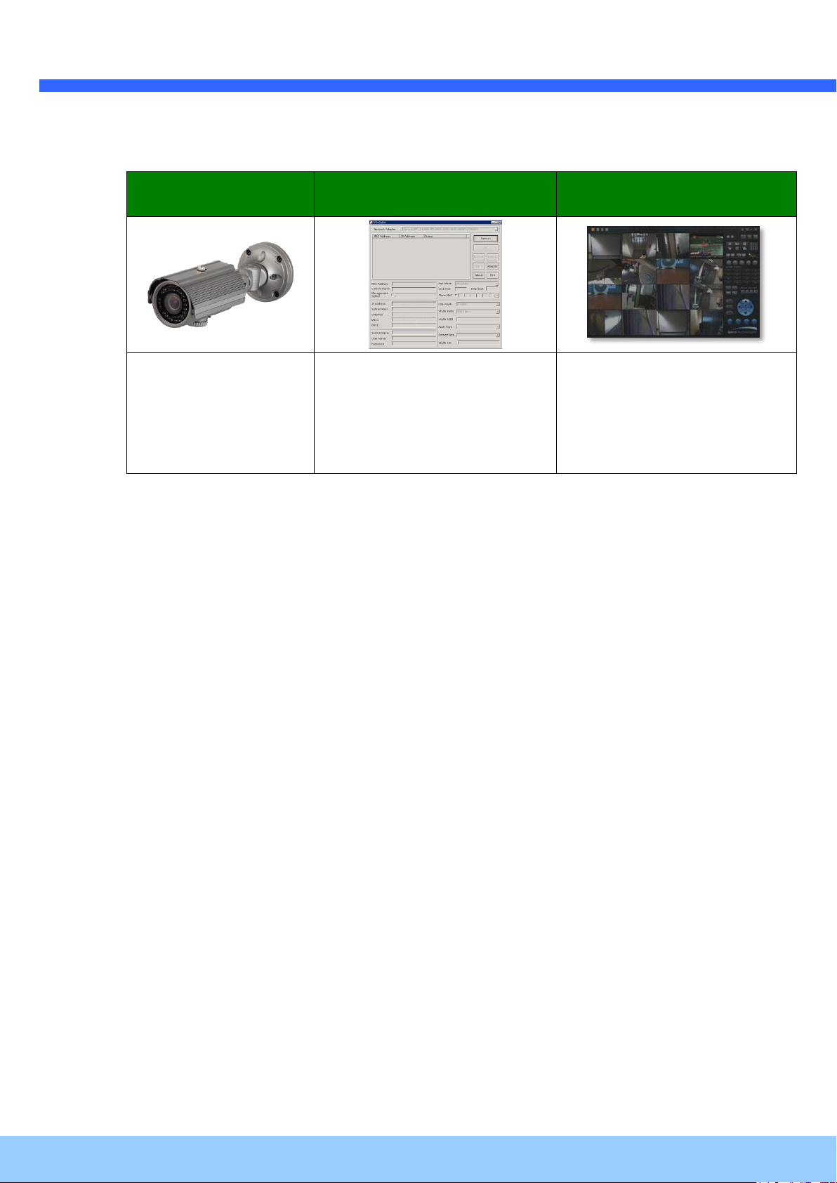
O2IR56B1
IP Installer
VMS Software
(Speco NVR)
Weatherproof
Bullet IP Camera
PC software to allocate an IP
address to the IP Camera
PC software to view and record
the A/V streaming data transmitted
from IP camera.
(Simultaneous support of up to 64
IP cameras@D1)
2.2. Product Preview
Page 10
OO22IIRR5566BB11 UUsseer
r
’
’
ss GGuuiiddee
Rev.1.3 (June, 2013)
10
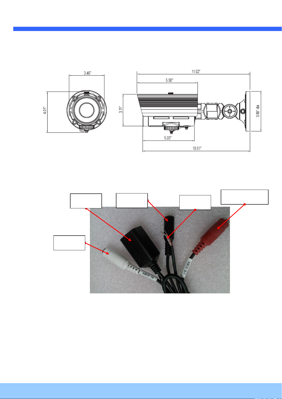
Audio-In
LAN
Power
Audio-Out
Sensor
2.3. Physical description
2.3.1. External View
Figure 2-1. External view of O2IR56B1
2.3.2. Connector information
Figure 2-2. Connector information
Rear
Page 11

OO22IIRR5566BB11 UUsseer
r
’
’
ss GGuuiiddee
Rev.1.3 (June, 2013)
11
Description
LINE OUT (+)
1 V p-p audio signal output for amplified speaker.
MIC/LINE GND (-)
Ground for audio signals.
MIC/LINE IN (+)
Audio input: Can be used either for microphone or applying
audio signals from other audio equipment.
SENSOR IN
Sensor In (+). NC/NO selectable in admin mode.
SENSOR IN GND
Ground for sensor
Focus control
SD card
Factory default
Figure 2-3. Factory Default switch and Video output connector
2.4. Functional Description
DC 12V: Power input for supplying 12V DC power.
MIC/LINE IN
Connect external audio source or microphone.
Line Out
Connect speakers with built in amplifier. Audio from remote site is output through Line out in bidirectional audio mode.
100Base-T
100Mbps Ethernet connector (RJ-45)
Alarm In/Out and Audio In
Used for connecting alarm sensor, microphone and speaker to O2IR56B1.
SENSOR IN
Connect external alarm sensor. Examples of sensing devices are infrared sensor, motion sensor,
heat/smoke sensor, magnetic sensor, etc. Connect the two wires of the sensors to “SNS In”.
Page 12
OO22IIRR5566BB11 UUsseer
r
’
’
ss GGuuiiddee
Rev.1.3 (June, 2013)
12
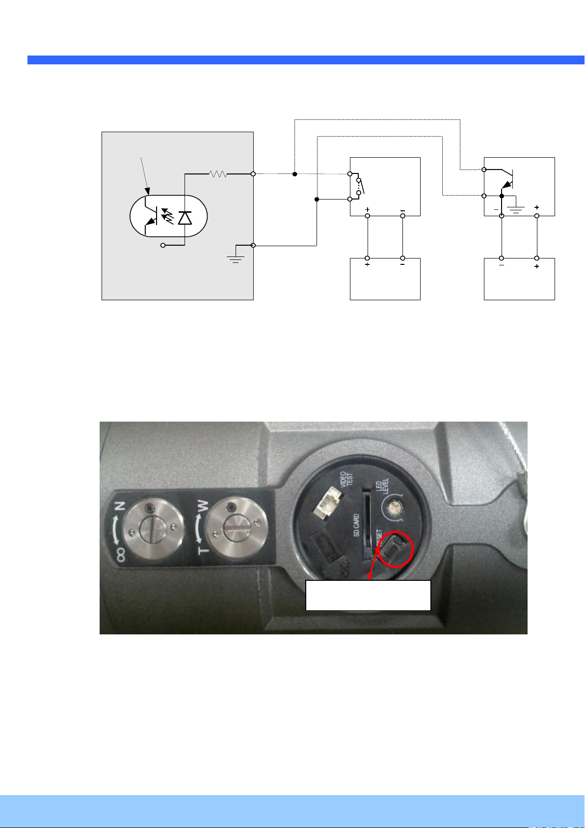
Sensor
Device
Sensor
Power
Supp ly
NO/NCType
Sensor1-
Sensor1+
+12V
GND
Sensor
Device
Sensor
Power
Supp ly
Open CollectorType
Photo Coupler
Factory default
The sensor type (NC/NO) can be set in the admin page. Multiple sensor devices can be
connected in parallel.
Figure 2-4. SENSOR input and connection of the sensor
Factory Default Switch
A switch provided for returning the IP camera to the factory default state. Open the dome
cover to access the switch. Press the switch for a few seconds while power is applied.
Figure 2-5. Factory Default Switch
Page 13

OO22IIRR5566BB11 UUsseer
r
’
’
ss GGuuiiddee
Rev.1.3 (June, 2013)
13
2.5. Accessories for installation
Figure 2-6. Accessories for installation of O2IR56B1.
Page 14

OO22IIRR5566BB11 UUsseer
r
’
’
ss GGuuiiddee
Rev.1.3 (June, 2013)
14
3. On Site Installation
Use Cables and conduits that are suitable for the installation and that are compliant to IP-67.
Particular attention should be paid in the installation so that no moisture is allowed to penetrate into
the unit through the cables or conduits during the lifetime of the product. Products of which the
internal parts are exposed to moisture because of improper installation are not covered by warranty.
3.1. Bracket
Figure 2-7. Bracket installation
1. Make a suitable hole for cabling
2. Connect the cables.
3. Fix the Base on the wall
4. Adjust the position of the lens for desired viewing of the site.
5. Adjust the focus
Page 15

OO22IIRR5566BB11 UUsseer
r
’
’
ss GGuuiiddee
Rev.1.3 (June, 2013)
15
Minimum Requirement
Recommended Specification
CPU
Intel Core i3 3Ghz
Intel Core i7
Main Memory
2GB
4GB
Operating System*
Windows XP
Windows 7 (64bit)
Web Browser
Internet Explorer 8, 9
Internet Explorer 8, 9
Graphic Card
Video RAM 256MB
Resolution 1920x1080
Video RAM 1GB
Higher than 1920x1080
Network
100 Base-T Ethernet
100 Base-T Ethernet
4. Getting Started
Brief information for the initial operation of O2IR56B1 is provided in this chapter.
4.1. PC Requirement
Audio/Video streaming data received from O2IR56B1 can be displayed or stored in a PC running
client programs. Minimum requirement of the PC is described below:
Page 16
OO22IIRR5566BB11 UUsseer
r
’
’
ss GGuuiiddee
Rev.1.3 (June, 2013)
16
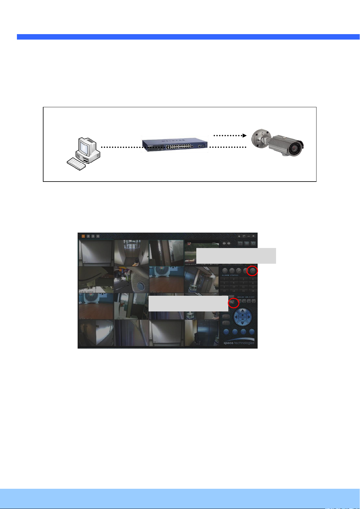
LAN switch
DC adapter
Admin Page Button
IP installer
4.2. Quick Installation Guide
1. Connect PC and O2IR56B1 to the network.
1) Prepare a PC to run programs for the installation and video connection
(PC is needed to assign an IP address to O2IR56B1)
2) Connect O2IR56B1 as shown in dotted line in Figure 4-1. DC power is applied through a DC
power adapter.
Figure 4-1. Power and network connection
2. Install Speco-NVR
Speco-NVR is a multi-channel VMS program for the IP camera or Video server. Install Speco-NVR on
remote PC to connect to these products. It is needed to assign connection information to Speco-NVR
program before connection.
Insert the CD provided with product into the PC and install Speco-NVR.
Figure 4-2. Speco-NVR
Follow the sequence below for setting the IP parameter
i) Run IP installer
ii) Click (1) in IP installer window.> Double click on (2) > Fill in (4) > make a selection in (5) >
Fill the parameters in (6)
iii) Click on (9) to apply the settings.
iv) You can connect to the admin page by clicking on (10).
Page 17

OO22IIRR5566BB11 UUsseer
r
’
’
ss GGuuiiddee
Rev.1.3 (June, 2013)
17
Click on the field in (3) for sorting and rearranging the list.
Select network mode that best suits from the drop down list in ⑤. You can choose either
Static or ADSL and Auto (DHCP), respectively. If ADSL and Auto are selected, the fields in ⑥
are deactivated. In case of ADSL, fill the User Name and Password in ⑧ with the values
provided by your ISP. If DDNS service is needed, Check at the box and fill the empty field with
hostname you want in ⑦.
1 2 3 6 4 9 5 7 8
10
Page 18

OO22IIRR5566BB11 UUsseer
r
’
’
ss GGuuiiddee
Rev.1.3 (June, 2013)
18
Note: Active-X module should be installed on your PC before actual connection. If your PC is
not connected to the internet, you cannot download Active-X module. Most convenient way of
installing the Active-X module is installing Speco-NVR which is available from the CD or our
web site.
Connection to Admin Page
Basic Control Buttons
Video Crop Control
[e.g.] Port 8080
[e.g.] Port 80
Port 80 (default) can be
omitted
3. Remote video connection to O2IR56B1
1) Connection through Web Viewer
Web Viewer offers the simplest way of video connection to O2IR56B1. For video connection,
enter the IP address of O2IR56B1 in the URL window of Internet Explorer as:
Figure 4-3. Web Viewer
Default ID and password of Admin Page are admin, 1234. For more detailed information, please refer
to the [Configuration_Guide] Guide.
2) Connection through Speco-NVR
Click the camera assignment button for setting camera address. Input the description,
address, Ch#, User ID, Password and port and then click the save button. After assignment
procedure, you must click the SAVE button. You can see the live video when you click the
live view button as below. When you exit Speco-NVR, you have to input the ID/PW,
admin/1234. Details for Speco-NVR can be found in [Speco-NVR User’s Guide].
Page 19

OO22IIRR5566BB11 UUsseer
r
’
’
ss GGuuiiddee
Rev.1.3 (June, 2013)
19
Camera Assignment
Camera Assignment
Live view
Save
Example
Exit Program
Default ID/PW:
admin/1234
Figure 4-4. Speco-NVR
4. Additional settings through connection to the Admin Page
All parameters of the camera are factory default out of the box. For a more sophisticated target
application, parameters need to be changed through the admin page. The admin page can be
connected through
”http://IP_address:HTTP_port_number”/admin.htm
ID and password of the administrator are required. Default ID and password are admin, 1234. It is
highly recommended to change the ID and password to prevent illegal access to the IP camera. For
more detailed information, please refer to the [Configuration_Guide] Guide.
Page 20

OO22IIRR5566BB11 UUsseer
r
’
’
ss GGuuiiddee
Rev.1.3 (June, 2013)
20
1
2
5. Troubleshooting
5.1. No power is applied
In case of Standard PoE (Power over Ethernet)
Power supply through standard PoE is possible only when the following conditions are
met.
1. Standard PoE is supported on the product.
2. The LAN switch supports standard PoE.
Make sure that both the IP camera and the LAN switch support standard PoE (IEEE
802.3af)
In case of DC adapter
If PoE is not applied, the power and network connection should be made through
separate cables. It is recommended to use DC adapter supplied by provider for the
feeding of the power. In case of replacing the DC power supply, make sure that the
power supply meets with the power requirement of the IP camera to prevent damage or
malfunction.
5.2. Cannot connect to the Video
Check the status of the network connection through a PING test.
Try the following on your PC:
- Start > Run > Cmd > Ping IP address (Ex : Ping 172.16.42.51)
- If “Reply from ~” message is returned ( in the figure below), the network connection is in
normal state. Try connection to the video again. If the problem persists, or refer to other
trouble shooting notes.
- If “Request timed out” message is returned. ( in the figure below), the network
connection or network setting is not in normal state. Check the network cable and settings.
Page 21

OO22IIRR5566BB11 UUsseer
r
’
’
ss GGuuiiddee
Rev.1.3 (June, 2013)
21
5.3. Windows Vista or Windows 7
Windows Vista and Windows 7 users need to configure UAC (User Access Control) and Privilege
Level for proper recording and still video captures in Speco NVR and Web Viewer.
<Windows Vista>
1. UAC (User Access Control) configuration
1) Double-click “User Accounts” in control panel
2) Double-click “Turn User Account Control on or off”
3) Uncheck “Use UAC to help protect your computer”
2. Privilege Level Control
1) Select “NVR” icon on the desktop
2) Click right mouse button and select “Properties”
3) Check “Privilege Level” in “Compatibility” tab
Page 22

OO22IIRR5566BB11 UUsseer
r
’
’
ss GGuuiiddee
Rev.1.3 (June, 2013)
22
<Windows 7>
1. UAC (User Access Control) configuration
1) Double-click “User Accounts” in control panel
2) Double-click “Change User Account Control setting”
3) Set to “Never notify”
2. Privilege Level Control
1) Select “NVR” icon on the desktop
2) Click right mouse button and select “properties”
3) Check “Privilege Level” in “Compatibility” tab
Page 23

OO22IIRR5566BB11 UUsseer
r
’
’
ss GGuuiiddee
Rev.1.3 (June, 2013)
23
Page 24

OO22IIRR5566BB11 UUsseer
r
’
’
ss GGuuiiddee
Rev.1.3 (June, 2013)
24
1. Model name
2. MAC address and Registration number
3. Purchase date
4. Description of the problem
5. Error message
5.4. Technical Assistance
If you need any technical assistance, please contact your dealer. For immediate service please
provide the following information.
Page 25
OO22IIRR5566BB11 UUsseer
r
’
’
ss GGuuiiddee
Rev.1.3 (June, 2013)
25
6. Appendix – OSD Menu Control
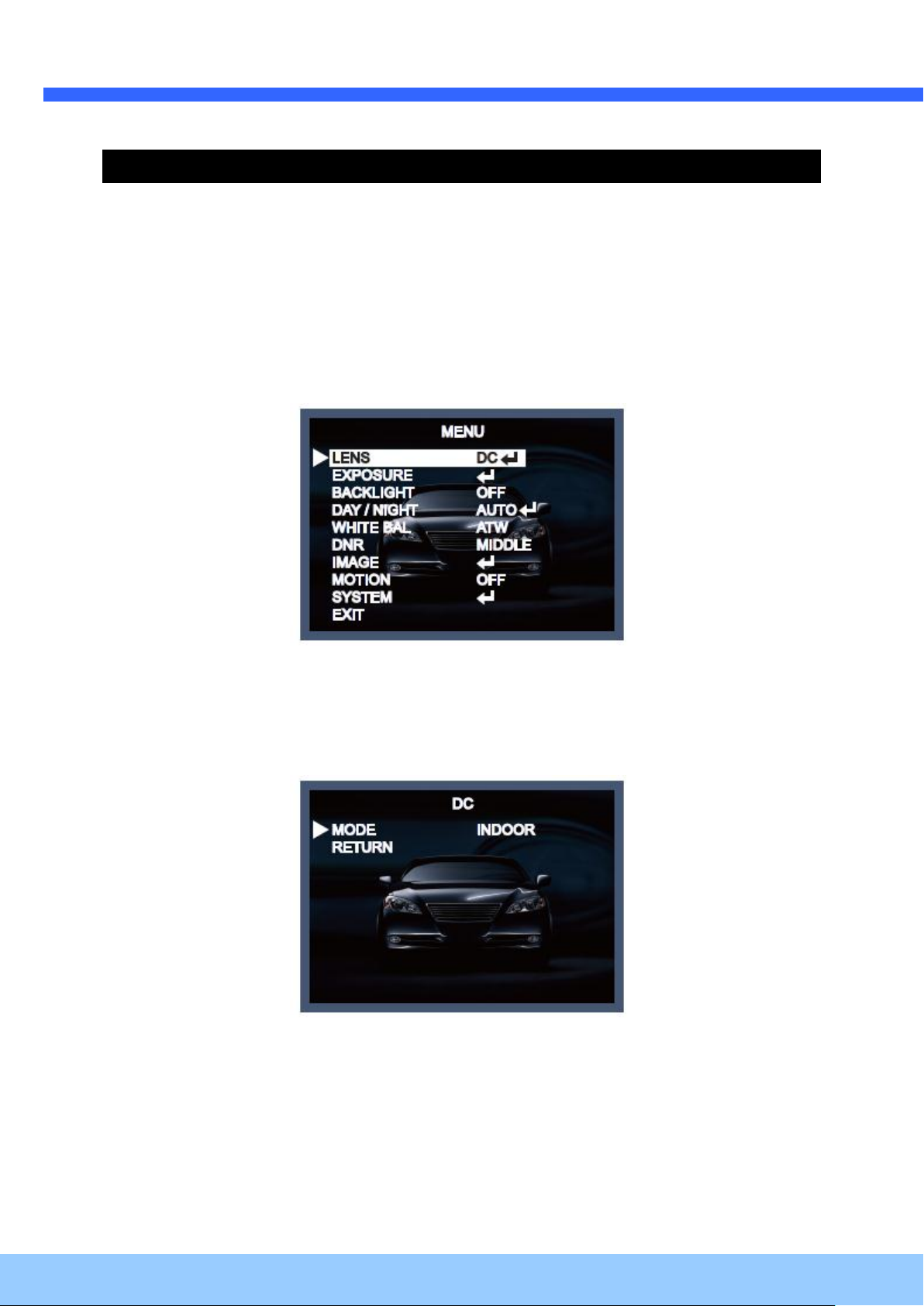
6.1. MENU Set Up
1. Press the SET key to access the menu mode.
2. Select the desired feature by using the UP/DOWN direction (/\ \/) of the SET key. If an ENTER
arrow is displayed next to the feature, press the SET key to access the feature's menu.
3. If there is a setting for this feature on the right side of the screen, use the LEFT/RIGHT direction to
switch between the settings and confirm your choice by pressing the SET key.
4. When the settings are completed, go to EXIT to save and leave the OSD.
6.2. LENS
If you are using a lens with manual Iris, set this item to MANUAL. If you are using a DC controlled lens,
set it to DC.
If you choose DC, you will be able to select if the camera is used indoors or outdoors.
The lens and shutter control will be automatically optimized according the present situation.
- MODE [INDOOR, OUTDOOR] :
If you choose INDOOR, the Iris and the shutter are set to fixed values. This will prevent a “rolling
effect” of the image. If you choose OUTDOOR, the Iris and shutter settings are flexible and will adjust
accordingly to the current brightness situation.
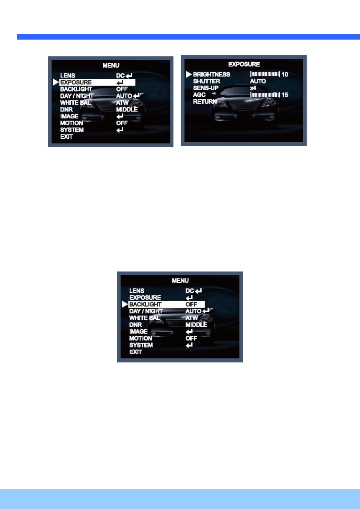
6.3. Exposure
When selecting ↵, the following submenu will appear.
The exposure is the amount of light received by the image sensor and is determined by the width of
lens diaphragm opening, the amount of exposure by the sensor (shutter speed) and other exposure
parameters. With this item, users can define how the Auto Exposure function.
Page 26
OO22IIRR5566BB11 UUsseer
r
’
’
ss GGuuiiddee
Rev.1.3 (June, 2013)
26
BRIGHTNESS [0 ~20] :
This function is used to adjust the brightness of the camera picture.
SHUTTER [1/25, 1/30, 1/60, 1/50, 1/120, 1/240, 1/500, 1/1000, 1/2000, 1/4000, 1/8000, 1/16000,
1/30000, 1/60000] :
You can select one of 14 options from 1/25 to 1/60000K for the fixed high speed electronic shutter,
which is mostly used for imaging a fast moving object.
SENS-UP [OFF, AUTO, x2~x64] :
Automatically detects the ambient level of darkness in a dark or low contrast scene to extend the
accumulated time, keeping the image bright and sharp.
AGC (Automatic Gain Control) [0-20] :
The AGC (Auto Gain Control) function is used to amplify the video signal when it falls below the set
parameter. As the AGC level increases, the overall screen gets brighter but the level of noise will also
increase at the same time.
6.4. Backlight
To overcome difficult light situations, the camera features different options to improve the image
quality.
HLC (High Light Compensation):
This function is used to surpress or mask a strong light source (for example, headlights of cars during
night-time) so that other subjects can be seen in more detail. If you select HLC, a submenu appears
where you can make finer adjustments.
- HLC LEVEL: Adjust the brightness level from which on the light source is to be masked out.
Page 27

OO22IIRR5566BB11 UUsseer
r
’
’
ss GGuuiiddee
Rev.1.3 (June, 2013)
27
BLC (Back Light Compensation):
This function is used to counterbalance the screen image by increasing the brightness so that a
subject which appears dark due to a strong backlight can be displayed in more detail. If you select
BLC, a submenu appears where you can make finer adjustments.
- H-POS/ V-POS/ H-SIZE/ V-SIZE: Define the position and size of the area of interest by changing the
position & size.
WDR:
The WDR (Wide Dynamic Range) function works to correct excessive light within the frame to
produce a usable image. When the image has simultaneous bright and dark areas, it makes both
areas distinct. If you select WDR, a submenu appears where you can make finer adjustments.
- WEIGHT [MIDDLE, HIGH, LOW]: Select the WDR level of the camera.
* The WDR function might lead to a reduced framerate and “ghost” effects in areas with very
bright background.
6.5. Day / Night
Here you can choose different settings to control the DAY&NIGHT function.
Page 28

OO22IIRR5566BB11 UUsseer
r
’
’
ss GGuuiiddee
Rev.1.3 (June, 2013)
28
COLOR: The camera is always in color mode regardless of the ambient conditions.
B/W: The camera is always in Black & White mode regardless of the ambient conditions.
EXTERN: Here you can activate the EXTERN function to activate the external Day & Night connector
on the rear panel of the camera. If you select EXTERN, a submenu appears where you can make
finer adjustments.
- DELAY [MIDDLE, HIGH, LOW]: Set the delay time for switching between COLOR and B/W.
AUTO: The camera will automatically switch between DAY and NIGHT mode, according to the lighting
condition. If you press the SET key, the AUTO sub-menu is selected.
- AGC THRES [0-20]: Execute the Day/Night switch depending on the AGC level that is used to
increase the brightness of the image. Higher values require a darker illumination to execute the switch.
- MARGIN [0-20]: Define the difference between the Day/Night & Night/Day switch based on AGC
THRES. Higher values will increase this distance and can help to prevent continuous switching
between Day & Night mode.
- DELAY [MIDDLE, HIGH, LOW]: Set the delay time for switching between COLOR and B/W.
Page 29
OO22IIRR5566BB11 UUsseer
r
’
’
ss GGuuiiddee
Rev.1.3 (June, 2013)
29
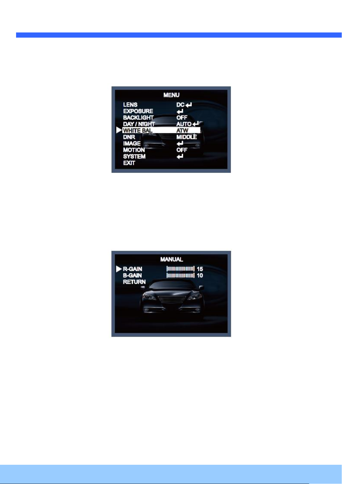
6.6. White Balance
The camera needs to find a reference color temperature, which is a way of measuring the color of a
light source, for calculating all the other colors. The unit for measuring this ratio is in degree Kelvin (K).
You can select one of the White Balance Control modes according to the installation condition.
ATW (Auto Tracking White Balance):
With the Auto Tracking White Balance function, the white balance in a scene will be automatically
adjusted while temperature color is changing. The ATW Mode is suitable for environments with a light
source having a color temperature in the range roughly from 1800 ~ 10500K.
AWB (Auto White Balance):
In this mode, white balance works within its color temperature range. This mode computes the white
balance value output using the color information from the entire screen. It outputs the proper value
using the color temperature radiating from a black subject.
PRESET:
This mode is set to the current white balance condition and keeps its value. Select this mode and then
press the SET key. If there is a change in location or light source, please repeat this procedure.
MANUAL:
Can be used for fine adjustment. Set the White Balance by first using ATW or AWC and then change
to MANUAL and press the SET key. Increase or decrease the value of R-Gain (Red) and B-Gain
(Blue) while
monitoring the color of the image.
- R-GAIN: Adjusts the White Balance for the color Red.
- B-GAIN: Adjusts the White Balance for the color Blue.
6.7. DNR(Digital Noise Reduction)
This function is used to improve the picture quality by filtering the noise which is generated under low
bright light conditions. You can set different levels here.
Page 30

OO22IIRR5566BB11 UUsseer
r
’
’
ss GGuuiiddee
Rev.1.3 (June, 2013)
30
6.8. Image
When selecting ↵, the following submenu will appear.
Here you can optimise the image quality by adjusting different options.
SHARPNESS [1 ~ 10] :
Adjusts the image sharpness. If the level goes up excessively, it may affect the video image and
generate a noise.
GAMMA [0.45 ~ 0.65] :
Changes the gamma curve of the camera.
COLOR GAIN [0 ~ 20] : Kontrollieren Sie die Farbsättigung des Video-Bildes.
MIRROR [ON, OFF] : Mirrors the image horizontally on the screen.
FLIP [ON, OFF] : Flips the image vertically on the screen.
D-ZOOM [1.0x~8.0x] : You can use the up to x8 bi-cubic linear digital zoom.
D-WDR [LOW, MIDDLE, HIGH, OFF] :
The WDR (Wide Dynamic Range) function works to correct excessive light within the frame to
produce a usable image. When the image has simultaneous bright and dark areas, it makes both
areas distinct.
Page 31
OO22IIRR5566BB11 UUsseer
r
’
’
ss GGuuiiddee
Rev.1.3 (June, 2013)
31
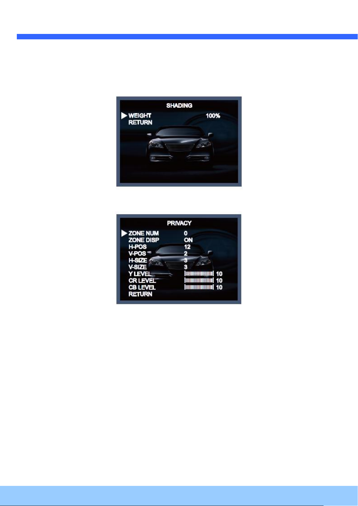
SHADING [ON, OFF] :
Compensates the shading effects of lenses when the lens is set to a very wide angle. This function
will reduce the brightness difference between the centre and the edges. If you select ON, a submenu
appears where you can make finer adjustments.
- WEIGHT [1%~100%] : You can set different levels here.
PRIVACY [ON, OFF] :
Masks areas that you want to hide on the screen. The camera can activate up to 32 privacy masks.
Switch between ON and OFF to activate or deactivate this function.
- ZONE NUM [0 ~ 32]: Select a mask out of the 32 mask areas and set the options below for the
selected mask.
- ZONE DISP [ON, OFF]: Choose ON to activate privacy masks and press OFF to deactivate masks.
- H-POS [0 ~ 60]: Define the horizontal start position of the privacy mask.
- V-POS [0 ~ 40]: Define the vertical start position of the privacy mask.
- H-SIZE [0 ~ 40]: Define the horizontal size of the privacy mask.
- V-SIZE [0 ~ 40]: Define the vertical size of the privacy mask.
- Y LEVEL [0 ~ 20]: Define the brightness of the mask color.
- CR LEVEL [0 ~ 20]: Define the red amount of the mask color.
- CB LEVEL [0 ~ 20]: Define the blue amount of the mask color.
6.9. Motion
This function is used to detect moving objects in the monitored area. When choosing ON, the
following submenu will appear where you can adjust the settings for the MOTION function.
Page 32

OO22IIRR5566BB11 UUsseer
r
’
’
ss GGuuiiddee
Rev.1.3 (June, 2013)
32
SENSITIVITY [1 ~ 20] : Set the sensitivity of the motion detection.
DET H-PS [0 ~ 60] : Define the horizontal start position of the monitoring area.
DET V-PS [0 ~ 40] : Define the vertical start position of the monitoring area.
DET H-SIZE [0 ~ 60] : Define the horizontal size of the monitoring area.
DET V-SIZE [0 ~ 40] : Define the vertical size of the monitoring area.
MOTION OSD [ON, OFF] : Controls the ON/OFF status of the motion detection block display.
ALARM [ON, OFF] :
When the ALARM function is activated, the camera will detect movement within a monitoring area and
then send an alarm signal automatically. The flash warning notice "MOTION !!!" will be displayed in
the upper left corner of the screen. When the camera is moved, the flash warning notice "MOVING !!!"
will be displayed in the upper left corner of the screen.
6.10. System
When selecting ↵, the following submenu will appear.
COLOR SPACE [COLOR1~3] : Select different color settings for a warmer or a colder image.
Page 33

OO22IIRR5566BB11 UUsseer
r
’
’
ss GGuuiiddee
Rev.1.3 (June, 2013)
33
FRAME RATE [25 FPS, 30 FPS] : Choose a frame rate.
CVBS [PAL, NTSC] : Select the video format that matches the present TV system
RESET [ON↓] : All settings will be restored to factory default.
Press the Set button in the exit menu to save the current settings and exit the Set Up menu.
6.11. Exit
Press the Set button in the exit menu to save the current settings and exit the Set Up menu.
 Loading...